EP2866202A2 - Processing of light fields by transforming to scale and depth space - Google Patents
Processing of light fields by transforming to scale and depth space Download PDFInfo
- Publication number
- EP2866202A2 EP2866202A2 EP20140187353 EP14187353A EP2866202A2 EP 2866202 A2 EP2866202 A2 EP 2866202A2 EP 20140187353 EP20140187353 EP 20140187353 EP 14187353 A EP14187353 A EP 14187353A EP 2866202 A2 EP2866202 A2 EP 2866202A2
- Authority
- EP
- European Patent Office
- Prior art keywords
- depth
- scale
- image
- ray
- transform
- Prior art date
- Legal status (The legal status is an assumption and is not a legal conclusion. Google has not performed a legal analysis and makes no representation as to the accuracy of the status listed.)
- Granted
Links
Images




Classifications
-
- G—PHYSICS
- G06—COMPUTING OR CALCULATING; COUNTING
- G06T—IMAGE DATA PROCESSING OR GENERATION, IN GENERAL
- G06T7/00—Image analysis
- G06T7/50—Depth or shape recovery
- G06T7/55—Depth or shape recovery from multiple images
- G06T7/557—Depth or shape recovery from multiple images from light fields, e.g. from plenoptic cameras
-
- G—PHYSICS
- G06—COMPUTING OR CALCULATING; COUNTING
- G06F—ELECTRIC DIGITAL DATA PROCESSING
- G06F17/00—Digital computing or data processing equipment or methods, specially adapted for specific functions
- G06F17/10—Complex mathematical operations
- G06F17/14—Fourier, Walsh or analogous domain transformations, e.g. Laplace, Hilbert, Karhunen-Loeve, transforms
-
- G—PHYSICS
- G06—COMPUTING OR CALCULATING; COUNTING
- G06T—IMAGE DATA PROCESSING OR GENERATION, IN GENERAL
- G06T2200/00—Indexing scheme for image data processing or generation, in general
- G06T2200/21—Indexing scheme for image data processing or generation, in general involving computational photography
-
- G—PHYSICS
- G06—COMPUTING OR CALCULATING; COUNTING
- G06T—IMAGE DATA PROCESSING OR GENERATION, IN GENERAL
- G06T2207/00—Indexing scheme for image analysis or image enhancement
- G06T2207/10—Image acquisition modality
- G06T2207/10052—Images from lightfield camera
-
- H—ELECTRICITY
- H04—ELECTRIC COMMUNICATION TECHNIQUE
- H04N—PICTORIAL COMMUNICATION, e.g. TELEVISION
- H04N13/00—Stereoscopic video systems; Multi-view video systems; Details thereof
- H04N13/20—Image signal generators
- H04N13/204—Image signal generators using stereoscopic image cameras
- H04N13/207—Image signal generators using stereoscopic image cameras using a single two-dimensional [2D] image sensor
- H04N13/232—Image signal generators using stereoscopic image cameras using a single two-dimensional [2D] image sensor using fly-eye lenses, e.g. arrangements of circular lenses
-
- H—ELECTRICITY
- H04—ELECTRIC COMMUNICATION TECHNIQUE
- H04N—PICTORIAL COMMUNICATION, e.g. TELEVISION
- H04N13/00—Stereoscopic video systems; Multi-view video systems; Details thereof
- H04N2013/0074—Stereoscopic image analysis
- H04N2013/0081—Depth or disparity estimation from stereoscopic image signals
Definitions
- This invention relates generally to the processing of light fields (including multi-view images) of three-dimensional scenes, for example the processing of light fields of a three dimensional scene captured by a plenoptic imaging system.
- Light fields have been first introduced in the computer graphics community for representing three-dimensional scenes via multiple views of that scene taken from different viewpoints.
- the light field of a scene is a seven-dimensional function that contains two-dimensional images (i.e., light field images) of the scene taken from any viewpoint in three-dimensional space, at any wavelength and any time instant.
- a computer can render the scene from any viewpoint because it has the explicit three-dimensional scene model, including its three-dimensional shape and texture. That is, the computer can render any of the light field images and therefore can also calculate the entire light field of the scene.
- systems have been developed for capturing a four-dimensional light field of three-dimensional scenes. These systems include camera arrays and plenoptic imaging systems. These systems typically capture a four-dimensional light field: two-dimensional images of a scene taken from various viewpoints on a two-dimensional surface (rather than allowing any viewpoint in three-dimensional space), at a certain wavelength (or wavelength band) and time instant. In these systems, the three-dimensional scene information is not explicitly captured. Rather, it is implicitly contained within the pixels of the captured four-dimensional light field.
- Extracting three-dimensional information from the four-dimensional light field is an inverse problem. It is a challenging problem because of the high dimensionality of light fields. Dense depth estimation (e.g., estimating depth of each pixel in a scene) is one of those challenging problems, because obtaining a globally smooth and consistent depth map typically requires global optimization, which is usually of prohibitive complexity for such high-dimensional data processing.
- the present invention overcomes the limitations of the prior art by transforming light field images of a three-dimensional scene (e.g., multi-view images) from an (image,view) domain to an (image,scale,depth) domain. Processing then occurs in the (image,scale,depth) domain.
- the light fields described above are captured in the (image,view) domain. They can be captured by a plenoptic imaging system, camera array or other types of multi-view imaging systems. It is a representation of a three-dimensional scene as two-dimensional images seen from multiple viewpoints. In the (image,scale,depth) domain, scale refers to different sizes of objects in the three-dimensional scene and depth refers to the depth of objects in the three-dimensional scene.
- scale-depth transform For convenience, the process of transforming from an (image,view) domain to an (image,scale,depth) domain may be referred to as scale-depth transform, and the resulting representation may be referred to as the scale-depth transform of the original light field.
- scale-depth transform is a generic term intended to include all transforms from the (image,view) domain to the (image,scale,depth) domain.
- the scale-depth transform is based on a Ray-Gaussian kernel, or its derivatives (including normalized derivatives).
- Ray in Ray-Gaussian refers to the fact that, for regularly spaced viewpoints on a flat plane, a point in the three-dimensional scene will manifest itself as a straight line in (image,view) space. The angle of this line corresponds to the depth of the point, where the mapping from the angle to the depth depends on camera parameters. Adjacent points at the same depth will then create a "ray” with a finite cross-sectional area in (image,view) space. The angle of the ray corresponds to the (depth) portion of the (image,scale,depth) domain.
- Gaussian in Ray-Gaussian refers to use of the Gaussian kernel to implement the (scale) portion of the (image,scale,depth) domain.
- This particular formulation has some advantageous properties that allow for a fast transform.
- This example Ray Gaussian kernel is defined for a two-dimensional slice of a light field, but the transform is not limited to this case as it can be extended to define a kernel for three-dimensional slices or even the entire light field.
- Examples of processing that can be performed in the (image,scale,depth) domain are depth estimation and 3D feature extraction.
- the scale-depth transform is based on the second derivative of the Ray-Gaussian kernel, and depth estimation is based on finding extrema in the scale-depth transform of the light field.
- the scale-depth transform is based on the first derivative of the Ray-Gaussian kernel, and finding extrema of the transformed light field can be used for 3D feature detection, such as edge detection.
- the light field can be parameterized as a four-dimensional function that represents the radiance of a light ray observed at location ( u, v ) , on a given reference surface, and coming from a point source at the location ( x, y ) , as shown in FIG. 1 .
- FIG. 1 shows a simplified three-dimensional scene with three objects 110A-C.
- FIG. 1 also shows a reference ( x,y ) plane and a reference ( u,v ) plane. Two points (u 1 ,v 1 ) and (u 2 ,v 2 ) are also shown.
- the (u,v) plane can be thought of as a viewpoint plane, and the coordinates (u,v) define a space that will be referred to as the (view) domain.
- the light field image I ( x,y,u 1 , v 1 ) is the image that would be seen by an observer from the viewpoint ( u 1 , v 1 ) .
- the (x,y) plane is drawn in object space but it is more appropriately thought of as a universal coordinate system defined in image space. It is universal in the sense that all light field images are defined relative to a common ( x,y ) coordinate system.
- the coordinates ( x,y ) define a space that will be referred to as the (image) domain.
- the light field I ( x , y , u , v ) may sometimes be referred to as an (image,view) domain representation of the three-dimensional scene, because it is a representation of the three-dimensional scene from the (image) and (view) domains.
- Devices may be used to capture images in this space.
- plenoptic cameras, camera arrays or other types of multi-view imaging devices may be used to capture images of the three-dimensional scene from different viewpoints.
- these devices sample the light field I (x,y,u, v ) at different values of ( u,v ).
- the set of images may also be referred to as multi-view images of the three-dimensional scene.
- FIG. 2 is a flow diagram of a method for processing light field images according to the invention.
- the provided 270 light field images are transformed 280 from the (image,view) domain to an (image,scale,depth) domain and processing 290 then occurs in that domain instead.
- the transformation 280 will be referred to as a scale-depth transform.
- Each of the (scale) and (depth) domains, including the transform to the (image,scale,depth) domain, is described in more detail below. For clarity, the explanations below use one-dimensional "images," but the extension to two dimensions is straightforward.
- the (image), (view), (scale), and (depth) dimensions are represented by the coordinates x, u , ⁇ and ⁇ , respectively.
- FIGS. 3A-3D we can see a line structure inherent to the characteristics of light fields with uniformly spaced viewpoints, where the angle of the line in the ( x,u ) domain corresponds to different depths in the scene.
- FIG. 3A shows two objects 210 and 220 which are at different depths.
- Object 220 is forward of object 210. It may or may not occlude object 210, depending on the viewpoint u .
- FIG. 3A is taken from viewpoint u 1 . From this viewpoint, object 210 occupies the x interval 211 and object 220 occupies the x interval 221. The two intervals 211 and 221 do not overlap and there is no occlusion.
- FIG. 3B shows the same two objects from a different viewpoint u 2 .
- FIG. 3B the two x intervals 212 and 222 are just touching.
- FIG. 3C shows the two objects from viewpoint u 3 .
- the two x intervals 213 and 223 are overlapping, which means that object 220 occludes part of object 210.
- the occluded region is the area of overlap.
- the area of overlap 239 represents the occlusion of object 210 by object 220. Since object 220 is forward of object 210, ray 229 will be unaffected by the overlap region 239. That is, the edges of ray 229 will continue to be parallel. In contrast, ray 219 will be minus the triangular overlap region 239.
- each point in an object creates a line in the ( x,u ) plane at an angle ⁇ with respect to the normal to the x axis.
- a set of adjacent points at the same depth creates a ray of a certain width, which forms an angle ⁇ with the vertical axis.
- These angles are labeled ⁇ 1 and ⁇ 2 in FIG. 3D . In the general four-dimensional case, these angles would be with respect to the normal to the ( x,y ) plane.
- the angle ⁇ will be referred to as the parallax angle.
- the parallax angle ⁇ depends on the depth location of the object.
- FIG. 4 shows an ( x,u ) slice from a light field for a grayscale scene.
- FIG. 4 also shows three rays 419, 429 and 439, of varying angle (depth) and width.
- the ( x,u ) representation of the three-dimensional scene can be transformed to the ( x , ⁇ ) domain.
- the ( ⁇ ) portion of this domain is one example of a (depth) domain due to the direct correspondence between parallax angle ⁇ and depth.
- each ray 219,229 corresponds to the spatial extent (i.e., size) of the corresponding object 210,220 in the three-dimensional scene. Objects of different sizes can be handled by using a scale space representation of the scene.
- the scale space representation of an image is obtained by convolving it with a kernel, whose scale changes from small scales (giving a narrow and sharp kernel) to large scales (giving a wide and smooth kernel).
- a kernel whose scale changes from small scales (giving a narrow and sharp kernel) to large scales (giving a wide and smooth kernel).
- image features of different sizes will be smoothed differently, i.e., small features will disappear at larger scales. Therefore, the scale-space framework allows scale invariant image processing, which is useful for dealing with the object size variations in images, for example due to object pose or camera orientation and distance.
- a commonly used kernel for constructing a scale space is the Gaussian kernel.
- Scale spaces based on the derivatives of the Gaussian kernel can also be constructed.
- Gaussian scale spaces allow recursive scale domain implementation via a Gaussian pyramid, as shown in FIGS. 5A-5B .
- element 510 represents a Gaussian scale space.
- the ( x,y ) coordinates are the image coordinates and ⁇ is the scale coordinate.
- Element 510 represents Eqn. (1), with log( ⁇ ) along the vertical axis.
- One way to construct element 510 is to directly calculate Eqn. (1) for different values of ⁇ , as represented by the different "slices" in element 510.
- element 520A is constructed by directly calculating Eqn. (1).
- Element 520B is obtained by downsampling the element 520A by a multiplicative factor, for example a factor of 2 (one octave). That is, the slices of element 520B are evaluated at values of ⁇ that are multiples of those used for element 520A, for example multiple of 2.
- the slices of element 520B can be constructed by filtering and downsampling the slices of element 520A, rather than calculating them by direct application of Eqn. (1).
- the slices in element 520C can be constructed by filtering and downsampling the slices of element 520B.
- the Ray-Gaussian is Gaussian in the x-direction and a ridge in the u -direction.
- the slant of the ridge is equal to tan ⁇ , which multiplies u in the shift of x in the exponent.
- u 0
- Lemma 1 shows a Ray Gaussian with scale ⁇ and angle ⁇ is equal to its downsampled version at scale s ⁇ and angle ⁇ , with values multiplied by s, for a downsampling factor s .
- downsampling in u is usually undesirable since that means we are dropping some views of the scene, whose number is usually small. Therefore, we show the following Lemma that addresses downsampling only in x.
- s ⁇ u 0
- FIG. 7A shows a direct approach.
- I is convolved 710 with for ⁇ ⁇ ⁇ 1 , ..., ⁇ n , 2 ⁇ 1 , ..., 2 ⁇ n , ..., 2 k ⁇ 1 , ..., 2 k ⁇ n ⁇ and for ⁇ ⁇ ⁇ ⁇ 1 , ..., ⁇ m ⁇ .
- n is the number of samples per octave of scale and (k +1) is the number of octaves
- m is the number of samples in the depth domain.
- the downsampling factor is chosen as 2, although other factors p could also be used. In FIG. 7A this is implemented by two loops 722, 724.
- FIG. 7B uses the propositions above to reduce the amount of computation by downsampling and forming a pyramid similar to the one in Fig. 5B . This can be especially useful for large light fields.
- I is convolved with for ⁇ ⁇ ⁇ ⁇ 1 , ..., ⁇ n ⁇ and for ⁇ ⁇ ⁇ ⁇ 1 , ..., ⁇ m ⁇ , as indicated by loops 722 and 726 in FIG. 7B . Note that the values of ⁇ span less than an octave, which is much less compared to FIG. 7A .
- I is then downsampled 730 by 2, and the down-sampled I is multiplied by 2 (according to Eq.(14)) and convolved with for ⁇ ⁇ ⁇ ⁇ 1 , ..., ⁇ n ⁇ and for ⁇ ⁇ ⁇ ⁇ 1 , ..., ⁇ m ⁇ .
- This convolution requires less computation because I has been downsampled. This is repeated ( k -1) times in loop 732.
- FIG. 7C is similar to FIG. 7B , except that the downsampling 737 occurs only in x and not in u. In that case, for each downsampling, the depth values ⁇ are also changed 737. That is, after downsampling, the down-sampled I is convolved with for ⁇ ⁇ ⁇ ⁇ 1 , ..., ⁇ n ⁇ and for ⁇ ⁇ ⁇ ⁇ ' 1 , ..., ⁇ ' m ⁇ .
- s ⁇ u 0
- s ⁇ u 0
- u 0
- ⁇ ' arctan( s tan ⁇ ) , ⁇ ⁇ (- ⁇ /2, ⁇ /2) and s>0.
- the scale-depth transform can be processed 290 in different ways to achieve different purposes.
- the (image,scale,depth) domain representation of the three-dimensional scene is processed to estimate depth in the three-dimensional scene.
- the following example is based on detecting rays in ( x,u ) space along with their position in the slice, their width (based on ⁇ ) and their angle (based on ⁇ ) .
- FIG. 8 shows a flow diagram for achieving this based on the Ray-Gaussian transform.
- FIG. 8 is an example of the process shown in FIG. 2 .
- the transformation step 880 is based on the normalized second derivative Ray Gaussian transform
- the processing step 890 is based on finding extrema (local minima and maxima) of ( x ; ⁇ , ⁇ ) .
- the parameters of extrema points ⁇ ( x p , ⁇ p , ⁇ p ) ⁇ give the following information about each ray p:
- ray 910 occludes ray 920 in ( x,u ) space. This is possible because ray 910 is at a steeper angle, meaning that it is closer to the camera and it makes sense for a closer object to occlude a farther object.
- ray 920 occludes ray 910, but ray 920 represents a farther object.
- One approach for handling such cases with overlapping rays is to remove the "occluded" ray 910 from the set of all rays. For situations conforming to FIG. 9A , we keep the rays and we can additionally record the information about the occlusion.
- the dashed lines in FIG. 8 denote an additional processing path to detect edges and their angles in the three-dimensional scene. This will be described in more detail below.
- This information can also be used to improve the depth assignment. For example, we can combine confidence values from ray detection and edge detection to obtain better depth assignments. We can also eliminate weak rays that do not have sharp edges on both sides, as those may be erroneous.
- Edges are usually informative image features. Since we get a depth value assigned to each edge feature, our method effectively performs 3D feature detection.
- a flowchart of an edge feature detection method is shown in the dashed boxes of FIG. 8 .
- the transformation step 980 is based on the normalized first derivative Ray Gaussian transform
- the processing step 990 is based on finding extrema (local minima and maxima) of ( x; ⁇ , ⁇ ) .
- Occlusion detection 992 can also be applied to edge detection.
- the approach shown in the dashed boxes of FIG. 8 can be generalized for other types of feature detection.
- the processing step 990 would be replaced with different processing, depending on the desired feature detection. For example, we can also look for corners as image features, by finding extrema in the 4D volume of concatenated scale-depth transforms, where the concatenation is along the second image dimension y .
- FIG. 10B The obtained depth map, after some post processing (median filtering and morphological closing) is shown in FIG. 10B .
- FIG. 10B lighter grayscales represent closer depths, and darker grayscales represent farther depths.
- FIG. 10C shows positions of detected 3D features overlaid on the original color image. The depth of each feature is indicated by the pseudo-color of the feature marker. Hotter (redder) colors indicate closer features and cooler (bluer) colors indicate farther features.
- FIG. 11 is a diagram of a plenoptic imaging system capable of capturing light field images suitable for use with the approaches described above.
- the system captures a plenoptic image of the scene 110.
- the plenoptic image is inherently a multi-view image of the scene 110.
- the plenoptic imaging system includes an image-forming optical module 1105, which in FIG. 11 is represented by a single lens element although it is understood that the optical module 1105 could contain multiple elements and/or non-lens elements (e.g., mirrors).
- the optical module 1105 forms a conventional optical image 1160 of scene 110.
- the optical module 1105 may also be referred to as the primary imaging module, subsystem or system.
- the optical image 1160 is formed at an image plane 1125 of the optical module 1105.
- the optical module 1105 is characterized by a pupil 1117 and pupil plane 1115, which in FIG. 11 is represented by a physical aperture stop co-located with the single lens element.
- the pupil 1117 and pupil plane 1115 need not be co-located with any of the optical elements within the optical module.
- a detector array would be located at image plane 1125 to capture the optical image 1160.
- an array 1120 of micro-imaging elements 1121 is located at the image plane 1125.
- the micro-imaging elements 1121 are shown as microlenses. Other elements can also be used, for example, an array of pinholes.
- the detector array 1130 is located behind (i.e., optically downstream of) the micro-imaging array 1120. More specifically, the detector array 1130 is positioned in a conjugate plane 1135 to the pupil plane 1115. That is, each micro-imaging element 1121 creates an image of the pupil plane 1115 at the conjugate plane 1135, which image is captured by the detector array 1130.
- each microlens 1121 forms an image 1170 of the pupil at the detector plane 1135.
- the image of the pupil is captured by a subset of detectors 1131 in the detector array 1130.
- Each microlens 1121 forms its own image 1170.
- the overall plenoptic image formed at detector plane 1135 will include an array of images 1170, one for each microlens 1121.
- This arrayed imaging effectively subdivides the detector array into superpixels 1133, each of which contains multiple detectors 1131.
- Each microlens 1121 images the pupil onto the corresponding superpixel 1133, with each pupil image then captured by detectors in the corresponding superpixel.
- Each detector 1131 collects the rays that travel through a portion of the pupil 1117.
- Each microlens 1121 collects the rays that originate from a portion of the scene 110.
- each detector 1131 collects the rays traveling in a certain direction from a portion of the scene 110. That is, each detector 1131 collects a small portion of the overall image of the scene, as taken from a specific viewpoint.
- a processor 1180 collects the data from the detector array 1130 and processes it accordingly. Processor 1180 may also perform the LF transform and other processing described above.
- FIG. 11 shows the capture of a light field by a plenoptic imaging system.
- other types of light field imaging systems can also be used, for example camera arrays.
- plenoptic cameras have particular optical properties that result in specific structure of light fields obtained from these cameras. This structure is reflected in a deterministic relation between scale and angle of rays in the (image,view) domain of the light field.
- plenoptic cameras with a main lens focused far away e.g. at the "hyperfocal distance" of the lens
- the main lens is focusing at an object closer than the hyperfocal distance
- light field containing objects closer than the focusing distance are characterized by rays with larger parallax angles and larger blur.
- Objects further then the focusing distance are characterized by larger negative parallax angles and larger blur.
- light fields can be captured by systems other than plenoptic imaging systems, such as multi-aperture optical systems (a system with multiple lenses and one sensor array) or camera arrays with non-regular arrangements of cameras.
- the scale-depth light field transform can be processed for purposes other than the specific examples given above: segmentation, compression, object detection and recognition, object tracking, and 3D scene visualization to name a few.
- the scale space can be constructed using kernels other than the Gaussian kernel described above.
- the invention is implemented in computer hardware, firmware, software, and/or combinations thereof.
- Apparatus of the invention can be implemented in a computer program product tangibly embodied in a non-transitory machine-readable storage device for execution by a programmable processor; and method steps of the invention can be performed by a programmable processor executing a program of instructions to perform functions of the invention by operating on input data and generating output.
- the invention can be implemented advantageously in one or more computer programs that are executable on a programmable system including at least one programmable processor coupled to receive data and instructions from, and to transmit data and instructions to, a data storage system, at least one input device, and at least one output device.
- Each computer program can be implemented in a high-level procedural or object-oriented programming language, or in assembly or machine language if desired; and in any case, the language can be a compiled or interpreted language.
- Suitable processors include, by way of example, both general and special purpose microprocessors.
- a processor will receive instructions and data from a read-only memory and/or a random access memory.
- a computer will include one or more mass storage devices for storing data files; such devices include magnetic disks, such as internal hard disks and removable disks; magneto-optical disks; and optical disks.
- Storage devices suitable for tangibly embodying computer program instructions and data include all forms of non-volatile memory, including by way of example semiconductor memory devices, such as EPROM, EEPROM, and flash memory devices; magnetic disks such as internal hard disks and removable disks; magneto-optical disks; and CD-ROM disks. Any of the foregoing can be supplemented by, or incorporated in, ASICs (application-specific integrated circuits) and other forms of hardware.
- ASICs application-specific integrated circuits
Landscapes
- Engineering & Computer Science (AREA)
- Physics & Mathematics (AREA)
- General Physics & Mathematics (AREA)
- Theoretical Computer Science (AREA)
- Mathematical Physics (AREA)
- Data Mining & Analysis (AREA)
- Computational Mathematics (AREA)
- Mathematical Analysis (AREA)
- Mathematical Optimization (AREA)
- Pure & Applied Mathematics (AREA)
- Algebra (AREA)
- Databases & Information Systems (AREA)
- Software Systems (AREA)
- General Engineering & Computer Science (AREA)
- Computer Vision & Pattern Recognition (AREA)
- Image Processing (AREA)
- Testing, Inspecting, Measuring Of Stereoscopic Televisions And Televisions (AREA)
- Image Analysis (AREA)
- Computer Graphics (AREA)
- Image Generation (AREA)
- Investigating Or Analysing Materials By Optical Means (AREA)
Abstract
Description
- This invention relates generally to the processing of light fields (including multi-view images) of three-dimensional scenes, for example the processing of light fields of a three dimensional scene captured by a plenoptic imaging system.
- Light fields have been first introduced in the computer graphics community for representing three-dimensional scenes via multiple views of that scene taken from different viewpoints. In general, the light field of a scene is a seven-dimensional function that contains two-dimensional images (i.e., light field images) of the scene taken from any viewpoint in three-dimensional space, at any wavelength and any time instant. In computer graphics applications, a computer can render the scene from any viewpoint because it has the explicit three-dimensional scene model, including its three-dimensional shape and texture. That is, the computer can render any of the light field images and therefore can also calculate the entire light field of the scene.
- Recently, systems have been developed for capturing a four-dimensional light field of three-dimensional scenes. These systems include camera arrays and plenoptic imaging systems. These systems typically capture a four-dimensional light field: two-dimensional images of a scene taken from various viewpoints on a two-dimensional surface (rather than allowing any viewpoint in three-dimensional space), at a certain wavelength (or wavelength band) and time instant. In these systems, the three-dimensional scene information is not explicitly captured. Rather, it is implicitly contained within the pixels of the captured four-dimensional light field.
- Extracting three-dimensional information from the four-dimensional light field is an inverse problem. It is a challenging problem because of the high dimensionality of light fields. Dense depth estimation (e.g., estimating depth of each pixel in a scene) is one of those challenging problems, because obtaining a globally smooth and consistent depth map typically requires global optimization, which is usually of prohibitive complexity for such high-dimensional data processing.
- Therefore, there is a need for light field processing approaches that efficiently and robustly extract depth and other information from light fields.
- The present invention overcomes the limitations of the prior art by transforming light field images of a three-dimensional scene (e.g., multi-view images) from an (image,view) domain to an (image,scale,depth) domain. Processing then occurs in the (image,scale,depth) domain. The light fields described above are captured in the (image,view) domain. They can be captured by a plenoptic imaging system, camera array or other types of multi-view imaging systems. It is a representation of a three-dimensional scene as two-dimensional images seen from multiple viewpoints. In the (image,scale,depth) domain, scale refers to different sizes of objects in the three-dimensional scene and depth refers to the depth of objects in the three-dimensional scene.
- For convenience, the process of transforming from an (image,view) domain to an (image,scale,depth) domain may be referred to as scale-depth transform, and the resulting representation may be referred to as the scale-depth transform of the original light field. Different transformations are possible and the term "scale-depth transform" is a generic term intended to include all transforms from the (image,view) domain to the (image,scale,depth) domain.
- In one approach, the scale-depth transform is based on a Ray-Gaussian kernel, or its derivatives (including normalized derivatives). "Ray" in Ray-Gaussian refers to the fact that, for regularly spaced viewpoints on a flat plane, a point in the three-dimensional scene will manifest itself as a straight line in (image,view) space. The angle of this line corresponds to the depth of the point, where the mapping from the angle to the depth depends on camera parameters. Adjacent points at the same depth will then create a "ray" with a finite cross-sectional area in (image,view) space. The angle of the ray corresponds to the (depth) portion of the (image,scale,depth) domain. "Gaussian" in Ray-Gaussian refers to use of the Gaussian kernel to implement the (scale) portion of the (image,scale,depth) domain. An example of a Ray-Gaussian kernel for a two-dimensional slice of a light field is

where x is a coordinate from the (image) domain, u is a (view) coordinate, σ is a (scale) coordinate, and ϕ is a (depth) coordinate. This particular formulation has some advantageous properties that allow for a fast transform. This example Ray Gaussian kernel is defined for a two-dimensional slice of a light field, but the transform is not limited to this case as it can be extended to define a kernel for three-dimensional slices or even the entire light field. - Examples of processing that can be performed in the (image,scale,depth) domain are depth estimation and 3D feature extraction. In one approach, the scale-depth transform is based on the second derivative of the Ray-Gaussian kernel, and depth estimation is based on finding extrema in the scale-depth transform of the light field. In another approach, the scale-depth transform is based on the first derivative of the Ray-Gaussian kernel, and finding extrema of the transformed light field can be used for 3D feature detection, such as edge detection.
- Other aspects of the invention include methods, devices, systems, components, and applications related to the concepts described above.
- The invention has other advantages and features which will be more readily apparent from the following detailed description of the invention and the appended claims, when taken in conjunction with the accompanying drawings.
-
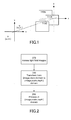
FIG. 1 is a diagram illustrating a three-dimensional scene. -
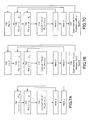
FIG. 2 is a flow diagram of a method for processing light field images according to the invention. -
FIGS. 3A-3C are diagrams illustrating two objects viewed from three different viewpoints. -
FIG. 3D is a diagram illustrating an (x,u) slice of the corresponding light field. -
FIG. 4 shows rays superimposed on an (x,u) slice from a light field for a grayscale scene. -
FIG. 5A illustrates a Gaussian scale space for a two-dimensional image. -
FIG. 5B is a diagram illustrating a Gaussian pyramid. -
FIG. 6 shows an example of a Ray-Gaussian kernel with ϕ = π/4 and σ=6. -
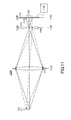
FIGS. 7A-7C are flow diagrams showing different methods for calculating a Ray-Gaussian transform. -
FIG. 8 is a flow diagram illustrating depth estimation. -
FIGS. 9A-9B are diagrams illustrating possible occlusions. -
FIG. 10A is one image from a set of light field images. -
FIG. 10B shows depth estimation for the set of light field images. -
FIG. 10C shows feature extraction for the set of light field images. -
FIG. 11 is a diagram of a plenoptic imaging system. - The figures depict embodiments of the present invention for purposes of illustration only. One skilled in the art will readily recognize from the following discussion that alternative embodiments of the structures and methods illustrated herein may be employed without departing from the principles of the invention described herein.
- The figures and the following description relate to preferred embodiments by way of illustration only. It should be noted that from the following discussion, alternative embodiments of the structures and methods disclosed herein will be readily recognized as viable alternatives that may be employed without departing from the principles of what is claimed.
- In the following example, we express the light field as radiance at any point in space in any given direction. The light field can be parameterized as a four-dimensional function that represents the radiance of a light ray observed at location (u, v), on a given reference surface, and coming from a point source at the location (x, y), as shown in
FIG. 1 . We denote the light field as I(x,y,u,v). -
FIG. 1 shows a simplified three-dimensional scene with threeobjects 110A-C.FIG. 1 also shows a reference (x,y) plane and a reference (u,v) plane. Two points (u1,v1) and (u2,v2) are also shown. The (u,v) plane can be thought of as a viewpoint plane, and the coordinates (u,v) define a space that will be referred to as the (view) domain. The light field image I(x,y,u 1,v 1) is the image that would be seen by an observer from the viewpoint (u1, v1 ). It can be thought of as the image that would be captured by a pinhole camera where the pinhole is located at position (u1,v1 ). Similarly, the light field image I(x,y,u2 ,v 2) is the image that would be seen by an observer located at viewpoint (u2,v2). InFIG. 1 , the (x,y) plane is drawn in object space but it is more appropriately thought of as a universal coordinate system defined in image space. It is universal in the sense that all light field images are defined relative to a common (x,y) coordinate system. The coordinates (x,y) define a space that will be referred to as the (image) domain. - Thus, the light field I(x,y,u,v) may sometimes be referred to as an (image,view) domain representation of the three-dimensional scene, because it is a representation of the three-dimensional scene from the (image) and (view) domains. Devices may be used to capture images in this space. For example, plenoptic cameras, camera arrays or other types of multi-view imaging devices may be used to capture images of the three-dimensional scene from different viewpoints. Mathematically, these devices sample the light field I(x,y,u,v) at different values of (u,v). The set of images may also be referred to as multi-view images of the three-dimensional scene. However, as discussed previously, it can be difficult to directly process these multi-view images to extract the three-dimensional information that is inherently captured within them.
-
FIG. 2 is a flow diagram of a method for processing light field images according to the invention. Instead of processing the light field images directly in the (image,view) domain, the provided 270 light field images are transformed 280 from the (image,view) domain to an (image,scale,depth) domain and processing 290 then occurs in that domain instead. Thetransformation 280 will be referred to as a scale-depth transform. Each of the (scale) and (depth) domains, including the transform to the (image,scale,depth) domain, is described in more detail below. For clarity, the explanations below use one-dimensional "images," but the extension to two dimensions is straightforward. The (image), (view), (scale), and (depth) dimensions are represented by the coordinates x, u, σ and ϕ, respectively. - If we look at some examples of two-dimensional slices I(x,u) of light fields, as shown in
FIGS. 3A-3D , we can see a line structure inherent to the characteristics of light fields with uniformly spaced viewpoints, where the angle of the line in the (x,u) domain corresponds to different depths in the scene.FIG. 3A shows twoobjects Object 220 is forward ofobject 210. It may or may not occludeobject 210, depending on the viewpoint u. -
FIG. 3A is taken from viewpoint u1. From this viewpoint,object 210 occupies thex interval 211 andobject 220 occupies thex interval 221. The twointervals FIG. 3D shows a two-dimensional (x,u) slice of the light field for these two objects. The x-slice ofFIG. 3A is marked by u1 on the vertical u axis. The twointervals FIG. 3D. FIG. 3B shows the same two objects from a different viewpoint u2 . From this viewpoint,object 210 occupies thex interval 212 andobject 220 occupies thex interval 222. This is also shown by the two line segments at coordinate u=u2 inFIG. 3D . Note that there is a shift of these segments with respect to the segments at coordinate u=u1. This relative shift due to viewpoint change is called the parallax. InFIG. 3B , the two xintervals FIG. 3C shows the two objects from viewpoint u3 . Here,object 210 occupies thex interval 213 andobject 220 occupies thex interval 223, as also shown by the two line segments at u=u3 inFIG. 3D . The two xintervals object 220 occludes part ofobject 210. The occluded region is the area of overlap. Repeating this process for other viewpoints u results in the twotrapezoids FIG. 3D , which will be referred to as rays. The area ofoverlap 239 represents the occlusion ofobject 210 byobject 220. Sinceobject 220 is forward ofobject 210,ray 229 will be unaffected by theoverlap region 239. That is, the edges ofray 229 will continue to be parallel. In contrast,ray 219 will be minus thetriangular overlap region 239. - From
FIG. 3D , we see an inherent line structure. That is, each point in an object creates a line in the (x,u) plane at an angle ϕ with respect to the normal to the x axis. A set of adjacent points at the same depth creates a ray of a certain width, which forms an angle ϕ with the vertical axis. These angles are labeled ϕ1 and ϕ2 inFIG. 3D . In the general four-dimensional case, these angles would be with respect to the normal to the (x,y) plane. For convenience, the angle ϕ will be referred to as the parallax angle. The parallax angle ϕ depends on the depth location of the object. Due to parallax, objects that are farther in depth from the viewpoint u-plane produce lines with a smaller parallax angle ϕ.Ray 219, which corresponds to object 213 which is farther from the u axis has a lower parallax angle ϕ.Ray 229, which corresponds to object 223 which is closer to the u axis, has a larger parallax angle ϕ. In some configurations of camera arrays or plenoptic cameras, the angle ϕ can also be negative. These rays correspond to objects that are located further along the direction towards the viewpoint, than objects that produce vertical rays (i.e., rays with ϕ= 0). Generally, the angle ϕ can take values within the interval (-π/2, π/2). -
FIG. 4 shows an (x,u) slice from a light field for a grayscale scene.FIG. 4 also shows threerays - There is a direct correspondence between parallax angle ϕ and depth in the three-dimensional scene. As a result, the (x,u) representation of the three-dimensional scene can be transformed to the (x, ϕ) domain. The (ϕ) portion of this domain is one example of a (depth) domain due to the direct correspondence between parallax angle ϕ and depth.
- Returning to
FIG. 3D , the width of each ray 219,229 corresponds to the spatial extent (i.e., size) of the corresponding object 210,220 in the three-dimensional scene. Objects of different sizes can be handled by using a scale space representation of the scene. - In one approach, the scale space representation of an image is obtained by convolving it with a kernel, whose scale changes from small scales (giving a narrow and sharp kernel) to large scales (giving a wide and smooth kernel). At different levels of the scale space, image features of different sizes will be smoothed differently, i.e., small features will disappear at larger scales. Therefore, the scale-space framework allows scale invariant image processing, which is useful for dealing with the object size variations in images, for example due to object pose or camera orientation and distance.
- A commonly used kernel for constructing a scale space is the Gaussian kernel. A Gaussian scale space in the one-dimensional case (ignoring the viewpoint u for now) is defined as:

where
σ is the (scale) coordinate, and * denotes the convolution operator. - Scale spaces based on the derivatives of the Gaussian kernel can also be constructed. For example, the normalized first derivative of the Gaussian scale-space:

can be used for edge-detection, where "normalized" refers to the multiplication by σ. Namely, when a given signal I(x) = t(x - x0) where t(x) is a step function, we have:
- The normalized second derivative of the Gaussian scale-space:

can be used for blob detection, where "normalized" refers to the multiplication by σ2. This is because when I(x) = t(x - x0 ) - t(x - x 1), we have that

- One advantage of Gaussian scale spaces is that they allow recursive scale domain implementation via a Gaussian pyramid, as shown in
FIGS. 5A-5B . InFIG. 5A ,element 510 represents a Gaussian scale space. The (x,y) coordinates are the image coordinates and σ is the scale coordinate. For clarity, assume scaling in only one dimension.Element 510 represents Eqn. (1), with log(σ) along the vertical axis. One way to constructelement 510 is to directly calculate Eqn. (1) for different values of σ, as represented by the different "slices" inelement 510. - An alternate approach is to build a Gaussian pyramid, as shown in
FIG. 5B . In this case,element 520A is constructed by directly calculating Eqn. (1).Element 520B is obtained by downsampling theelement 520A by a multiplicative factor, for example a factor of 2 (one octave). That is, the slices ofelement 520B are evaluated at values of σ that are multiples of those used forelement 520A, for example multiple of 2. The slices ofelement 520B can be constructed by filtering and downsampling the slices ofelement 520A, rather than calculating them by direct application of Eqn. (1). Similarly, the slices in element 520C can be constructed by filtering and downsampling the slices ofelement 520B. - Now consider a specific example of transforming from the (image,view) domain to the (image,scale,depth) domain, based on the above specifics. In this example, the captured multi-view images are represented in the (image,view) domain by I(x,u). We want to transform the (image,view) domain representation I(x,u) to an (image,scale,depth) domain representation(x; υ,ψ). For convenience,
 (x; υ,ψ) may also be referred to as a scale-depth transform (or scale-depth space) of I(x,u).
- Let us first define a kernel that we will use in the transformation. We define the Ray-Gaussian kernel as:

where x and u are as defined inFIG. 2D , ϕ is the angle that the Ray-Gaussian kernel forms with the u-axis (i.e., angle with the normal to the x-axis) and σ is the width parameter of the kernel. The "Ray" in Ray-Gaussian refers to the rays that are present in (x,u) space. -
FIG. 6 shows an example of a Ray-Gaussian function with ϕ = π/4 and σ = 6. In this grayscale picture, the lighter pixels are higher values and the darker pixels are lower values. The Ray-Gaussian is Gaussian in the x-direction and a ridge in the u-direction. The slant of the ridge is equal to tan ϕ, which multiplies u in the shift of x in the exponent. This linear shift x 0 = u tan ϕ is chosen here to best represent the ray structures in the (image,view) domain for light fields obtained with the uniform spacing of viewpoints on a flat plane. - Note, however, that one can also choose different (and possibly nonlinear) parameterizations of shift x 0 = f(u) to represent different structures such as curved rays. The appropriate choice of f(u) depends on the geometry of the light field image acquisition. In the example of
FIG. 2 , each point in the three-dimensional scene creates a line in the (image,view) slice, and points at different depths correspond to lines at different angles. However, if the multi-view images are captured by non-uniform camera arrays on non-flat planes or plenoptic cameras with non-uniform microlens array density, then points at different depths in the three-dimensional scene may correspond to different curves in the (image,view) slice. The function f(u) is chosen accordingly. - We use the Ray-Gaussian kernel to construct the Ray-Gaussian transform(x; υ,ψ) of I(x,u), according to:


where u=0 is chosen because we are evaluating convolution only over x (image domain). That is,
Note here that(x; σ, ϕ) does not depend on u since the convolution is only over x, and that (x; σ, ϕ) has both scale σ and angle ϕ as parameters.
- Similarly, we define the n-th derivative of the Ray-Gaussian transform as:

- In the following, we show certain properties of the Ray-Gaussian function, which are beneficial for building the Ray-Gaussian transform. The next two Lemmas prove equalities related to scale change of the Ray-Gaussian and its downsampling or upsampling factor.
- Lemma 1: The following equality holds:

where s>0 is a scale factor. - Proof:

-
Lemma 1 shows a Ray Gaussian with scale σ and angle ϕ is equal to its downsampled version at scale sσ and angle ϕ, with values multiplied by s, for a downsampling factor s. In light fields, downsampling in u is usually undesirable since that means we are dropping some views of the scene, whose number is usually small. Therefore, we show the following Lemma that addresses downsampling only in x. - Lemma 2: The following equality holds:

where ϕ' = arctan(s tan ϕ), ϕ ∈ (-π/2, π/2) and s>0. - Proof: Since tan(ϕ') = s tan ϕ, we have:

- The second Lemma shows that a Ray Gaussian with scale σ and angle ϕ is equal to its downsampled version at scale sσ and angle ϕ' = arctan(s tan ϕ), with values multiplied by s, for a downsampling only in x by factor s.
- Equipped with these two Lemmas, we can now show the following properties of the Ray-Gaussian transform

- Proposition 1: If we have a light field slice J(x, u) such that J(x, u) = I(sx, su) (i.e., I is a downsampled or upsampled version of J), then:

- Proposition 2: If we have a light field slice J(x, u) such that J(x, u) = I(sx, u) (i.e., I is a downsampled or upsampled version of J only over x), then:

- These two properties of the Ray-Gaussian transform indicate that we can build the transform(x; σ, ϕ) of light field I in several ways.

FIG. 7A shows a direct approach. In this approach, I is convolved 710 withfor σ ∈ {σ1, ..., σn, 2σ1, ..., 2σn, ..., 2kσ1, ..., 2kσn } and for ϕ ∈ {ϕ1, ..., ϕm }. In this formulation, n is the number of samples per octave of scale and (k+1) is the number of octaves, and m is the number of samples in the depth domain. The downsampling factor is chosen as 2, although other factors p could also be used. In
FIG. 7A this is implemented by twoloops -
FIG. 7B uses the propositions above to reduce the amount of computation by downsampling and forming a pyramid similar to the one inFig. 5B . This can be especially useful for large light fields. In this approach, I is convolved withfor σ ∈ {σ 1, ..., σn } and for ϕ ∈ {ϕ 1, ..., ϕm }, as indicated by
loops FIG. 7B . Note that the values of σ span less than an octave, which is much less compared toFIG. 7A . I is then downsampled 730 by 2, and the down-sampled I is multiplied by 2 (according to Eq.(14)) and convolved withfor σ ∈ {σ1, ..., σn } and for ϕ ∈ {ϕ 1 , ..., ϕm }. This convolution requires less computation because I has been downsampled. This is repeated (k-1) times in
loop 732. -
FIG. 7C is similar toFIG. 7B , except that the downsampling 737 occurs only in x and not in u. In that case, for each downsampling, the depth values ϕ are also changed 737. That is, after downsampling, the down-sampled I is convolved withfor σ ∈ {σ 1, ..., σn } and for ϕ ∈ {ϕ' 1, ..., ϕ'm }.
- We can also show that similar properties hold for transforms built upon the first and second derivatives of the Ray-Gaussian.
- Proposition 3: If we have a light field slice J(x, u) such that J(x, u) = I(sx, su) (i.e., I is a downsampled or upsampled version of J), then:

- Proposition 4: If we have a light field slice J(x, u) such that J(x, u) = I(sx, u) (i.e., I is a downsampled or upsampled version of J only over x), then:

where ϕ' = arctan(s tan ϕ), ϕ ∈ (-π/2, π/2) and s>0. - We can see from Propositions 3 and 4 that for construction of first derivative Ray-Gaussian transforms(x; σ, ϕ), we can use the "normalized" Ray-Gaussian derivative


FIGS. 7A-7C . - Proposition 5: If we have a light field slice J(x, u) such that J(x, u) = I(sx, su) (i.e., I is a downsampled or upsampled version of J), then:

- Proposition 6: If we have a light field slice J(x, u) such that J(x, u) = I(sx, u) (i.e., I is a downsampled or upsampled version of J only over x), then:

where ϕ' = arctan(s tan ϕ), ϕ ∈ (-π/2, π/2) and s>0. - Similarly, we can see from Propositions 5 and 6 that for construction of second derivative Ray-Gaussian transforms(x; σ, ϕ), we can use the "normalized" Ray-Gaussian second derivative:


FIGS. 7A-7C . - It is useful to show one more property of the Ray-Gaussian kernel, which relates to the preservation of the inner product with a light field under change of angles.
- Proposition 7: If we have a light field that satisfies I(x, u) = f(x - au), where a is a constant (which is the case when there are no occlusions), then:

- Similar propositions hold for the derivativesand
 This is an important property for depth estimation because it assures that there is no bias with respect to the angle of rays and thus no bias with respect to depth values.
- Returning to
FIG. 2 , the scale-depth transform can be processed 290 in different ways to achieve different purposes. In one application, the (image,scale,depth) domain representation of the three-dimensional scene is processed to estimate depth in the three-dimensional scene. The following example is based on detecting rays in (x,u) space along with their position in the slice, their width (based on σ) and their angle (based on ϕ). -
FIG. 8 shows a flow diagram for achieving this based on the Ray-Gaussian transform.FIG. 8 is an example of the process shown inFIG. 2 . Here, thetransformation step 880 is based on the normalized second derivative Ray Gaussian transform
- The
processing step 890 is based on finding extrema (local minima and maxima) of(x; σ, ϕ). The parameters of extrema points {(xp, σp, ϕp )} give the following information about each ray p:
- position of the center of the ray xp
- width of the ray 2σ p
- angle of the ray ϕp
- From the angle ϕp we can get the depth dp of that ray (i.e., depth of the corresponding points in the three-dimensional scene) by using the camera calibration parameters as dp = fb/ tan(ϕp ), where f is camera focal length and b is inter-camera distance. For plenoptic cameras, we can evaluate a more precise angle-depth value assignment by simulating the plenoptic image formation using ray tracing or wave propagation. This second approach encompasses a more precise use of optical parameters in depth estimation.
- After we have detected the rays and found their parameters, we can further refine the results by applying additional techniques. One technique resolves occlusion conflicts 892 between overlapping rays. Since we have the position and width for each ray, we can find sets of rays that overlap, such as shown in
FIG. 3D . Once we have found overlapping rays, we can decide the ordering of rays from the foreground to the background. Because larger angle of rays indicates smaller depth (closer objects, larger parallax), rays with larger angles should be in the foreground as shown inFIG. 9A . InFIG. 9A ,ray 910 occludesray 920 in (x,u) space. This is possible becauseray 910 is at a steeper angle, meaning that it is closer to the camera and it makes sense for a closer object to occlude a farther object. - Due to noise in the images, detected rays sometimes conform to the situation presented in
FIG. 9B . In this example,ray 920 occludesray 910, butray 920 represents a farther object. One approach for handling such cases with overlapping rays is to remove the "occluded"ray 910 from the set of all rays. For situations conforming toFIG. 9A , we keep the rays and we can additionally record the information about the occlusion. - We can assign
depth 894 to pixels by combining information from detected rays that remained after theocclusion detection 892. We can also combine information from rays detected by processing scale-depth spaces from (x,u) slices and scale-depth spaces from (y,v) slices of the light field. Slices (x,u) correspond to views with horizontal parallax and slices (y,v) correspond to views with vertical parallax. For pixels with multiple options for assignment (i.e., multiple rays), we may choose the assignment with a higher confidence value. All other factors being equal, we pick the ray with the highest absolute value of the scale-depth space for that pixel. - The dashed lines in
FIG. 8 denote an additional processing path to detect edges and their angles in the three-dimensional scene. This will be described in more detail below. This information can also be used to improve the depth assignment. For example, we can combine confidence values from ray detection and edge detection to obtain better depth assignments. We can also eliminate weak rays that do not have sharp edges on both sides, as those may be erroneous. - We can detect edges in three-dimensional scenes and estimate depth values for those edges by finding extrema in the normalized first derivative Ray Gaussian transform


- position of the edge xq
- scale of the edge σ q
- angle of the edge ϕq
- Edges are usually informative image features. Since we get a depth value assigned to each edge feature, our method effectively performs 3D feature detection. A flowchart of an edge feature detection method is shown in the dashed boxes of
FIG. 8 . This is another example of the process shown inFIG. 2 . Here, thetransformation step 980 is based on the normalized first derivative Ray Gaussian transform
processing step 990 is based on finding extrema (local minima and maxima) of(x; σ, ϕ).
Occlusion detection 992 can also be applied to edge detection. - The approach shown in the dashed boxes of
FIG. 8 can be generalized for other types of feature detection. Theprocessing step 990 would be replaced with different processing, depending on the desired feature detection. For example, we can also look for corners as image features, by finding extrema in the 4D volume of concatenated scale-depth transforms, where the concatenation is along the second image dimension y. - We have evaluated depth estimation and 3D feature detection methods on the "truck" light field from the Stanford database. This is a (x, y, u, v) light field obtained with a camera gantry and it contains images with both horizontal and vertical camera displacements. There are in total 16 x 16 images. The grayscale version of one image is shown in
FIG. 10A . The following results are shown for grayscale versions of the light field, but the approaches described here can also be used to aggregate results from multiple color channels. - We have applied the Ray-Gaussian transform, ray detection and edge detection separately for (x,u) and (y,v) slices and then combined them prior to depth assignment. For depth map estimation, we have used information both from ray detection and edge detection. The obtained depth map, after some post processing (median filtering and morphological closing) is shown in
FIG. 10B . InFIG. 10B , lighter grayscales represent closer depths, and darker grayscales represent farther depths. Finally,FIG. 10C shows positions of detected 3D features overlaid on the original color image. The depth of each feature is indicated by the pseudo-color of the feature marker. Hotter (redder) colors indicate closer features and cooler (bluer) colors indicate farther features. -
FIG. 11 is a diagram of a plenoptic imaging system capable of capturing light field images suitable for use with the approaches described above. The system captures a plenoptic image of thescene 110. The plenoptic image is inherently a multi-view image of thescene 110. The plenoptic imaging system includes an image-formingoptical module 1105, which inFIG. 11 is represented by a single lens element although it is understood that theoptical module 1105 could contain multiple elements and/or non-lens elements (e.g., mirrors). Theoptical module 1105 forms a conventionaloptical image 1160 ofscene 110. Theoptical module 1105 may also be referred to as the primary imaging module, subsystem or system. Theoptical image 1160 is formed at animage plane 1125 of theoptical module 1105. Theoptical module 1105 is characterized by apupil 1117 andpupil plane 1115, which inFIG. 11 is represented by a physical aperture stop co-located with the single lens element. In more complexoptical modules 1105, thepupil 1117 andpupil plane 1115 need not be co-located with any of the optical elements within the optical module. - In a conventional imaging system, a detector array would be located at
image plane 1125 to capture theoptical image 1160. However, this is not the case for the plenoptic imaging system inFIG. 11 . In this particular example, anarray 1120 ofmicro-imaging elements 1121 is located at theimage plane 1125. InFIG. 11 , themicro-imaging elements 1121 are shown as microlenses. Other elements can also be used, for example, an array of pinholes. Thedetector array 1130 is located behind (i.e., optically downstream of) themicro-imaging array 1120. More specifically, thedetector array 1130 is positioned in aconjugate plane 1135 to thepupil plane 1115. That is, eachmicro-imaging element 1121 creates an image of thepupil plane 1115 at theconjugate plane 1135, which image is captured by thedetector array 1130. - In the case of microlenses, each
microlens 1121 forms animage 1170 of the pupil at thedetector plane 1135. The image of the pupil is captured by a subset ofdetectors 1131 in thedetector array 1130. Eachmicrolens 1121 forms itsown image 1170. Thus, the overall plenoptic image formed atdetector plane 1135 will include an array ofimages 1170, one for eachmicrolens 1121. This arrayed imaging effectively subdivides the detector array intosuperpixels 1133, each of which containsmultiple detectors 1131. Eachmicrolens 1121 images the pupil onto thecorresponding superpixel 1133, with each pupil image then captured by detectors in the corresponding superpixel. - Each
detector 1131 collects the rays that travel through a portion of thepupil 1117. Eachmicrolens 1121 collects the rays that originate from a portion of thescene 110. Thus, eachdetector 1131 collects the rays traveling in a certain direction from a portion of thescene 110. That is, eachdetector 1131 collects a small portion of the overall image of the scene, as taken from a specific viewpoint. By aggregating the data collected bydetectors 1131 which are operating from the same viewpoint, a complete image of the scene from that viewpoint can be constructed. By aggregating all the images from different viewpoints, a complete light field for the scene can be constructed. InFIG. 11 , aprocessor 1180 collects the data from thedetector array 1130 and processes it accordingly.Processor 1180 may also perform the LF transform and other processing described above. -
FIG. 11 shows the capture of a light field by a plenoptic imaging system. As mentioned previously, other types of light field imaging systems can also be used, for example camera arrays. - Many plenoptic cameras have particular optical properties that result in specific structure of light fields obtained from these cameras. This structure is reflected in a deterministic relation between scale and angle of rays in the (image,view) domain of the light field. For example, plenoptic cameras with a main lens focused far away (e.g. at the "hyperfocal distance" of the lens) produce light fields where rays characterized by a small parallax angle have small blur (or no blur) and rays characterized by larger parallax angles have larger blur. Since blur (smoothness) affects the level of scale at which the ray is detected through scale-depth processing, there is a deterministic relation between depth and scale. These type of relations can be advantageously exploited for reducing the complexity of search through the (image,scale,depth) space. For example, if there is a one-to-one relation between scale and depth given by a function f, the three-dimensional search within the (image,scale,depth) space can be reduced to a two-dimensional search within (image,f(scale,depth)). This can be exploited in both examples of application to depth estimation and 3D feature detection, as well as in other applications of scale-depth processing.
- In the case that the main lens is focusing at an object closer than the hyperfocal distance, light field containing objects closer than the focusing distance are characterized by rays with larger parallax angles and larger blur. Objects further then the focusing distance are characterized by larger negative parallax angles and larger blur.
- Although the detailed description contains many specifics, these should not be construed as limiting the scope of the invention but merely as illustrating different examples and aspects of the invention. It should be appreciated that the scope of the invention includes other embodiments not discussed in detail above. For example, light fields can be captured by systems other than plenoptic imaging systems, such as multi-aperture optical systems (a system with multiple lenses and one sensor array) or camera arrays with non-regular arrangements of cameras. As another example, the scale-depth light field transform can be processed for purposes other than the specific examples given above: segmentation, compression, object detection and recognition, object tracking, and 3D scene visualization to name a few. As a final example, the scale space can be constructed using kernels other than the Gaussian kernel described above. Various other modifications, changes and variations which will be apparent to those skilled in the art may be made in the arrangement, operation and details of the method and apparatus of the present invention disclosed herein without departing from the spirit and scope of the invention as defined in the appended claims. Therefore, the scope of the invention should be determined by the appended claims and their legal equivalents.
- In alternate embodiments, the invention is implemented in computer hardware, firmware, software, and/or combinations thereof. Apparatus of the invention can be implemented in a computer program product tangibly embodied in a non-transitory machine-readable storage device for execution by a programmable processor; and method steps of the invention can be performed by a programmable processor executing a program of instructions to perform functions of the invention by operating on input data and generating output. The invention can be implemented advantageously in one or more computer programs that are executable on a programmable system including at least one programmable processor coupled to receive data and instructions from, and to transmit data and instructions to, a data storage system, at least one input device, and at least one output device. Each computer program can be implemented in a high-level procedural or object-oriented programming language, or in assembly or machine language if desired; and in any case, the language can be a compiled or interpreted language. Suitable processors include, by way of example, both general and special purpose microprocessors. Generally, a processor will receive instructions and data from a read-only memory and/or a random access memory. Generally, a computer will include one or more mass storage devices for storing data files; such devices include magnetic disks, such as internal hard disks and removable disks; magneto-optical disks; and optical disks. Storage devices suitable for tangibly embodying computer program instructions and data include all forms of non-volatile memory, including by way of example semiconductor memory devices, such as EPROM, EEPROM, and flash memory devices; magnetic disks such as internal hard disks and removable disks; magneto-optical disks; and CD-ROM disks. Any of the foregoing can be supplemented by, or incorporated in, ASICs (application-specific integrated circuits) and other forms of hardware.
- The present application is based on and claims the benefit of priority of
U. S. Patent Application Serial No. 14/064,090, filed on October 25, 2013 , the contents of which are incorporated herein by reference in their entirety.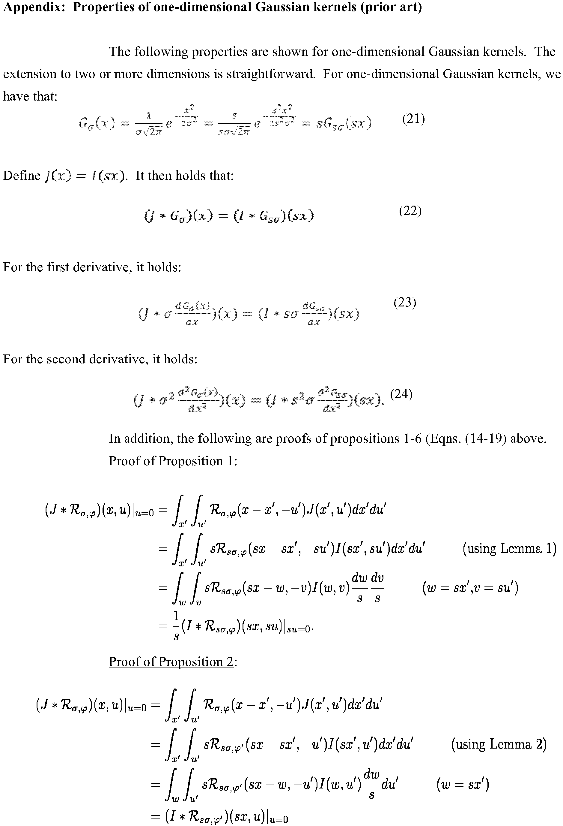


Claims (15)
- A method for processing light field images of a three-dimensional scene, the method implemented on a computer system and comprising:accessing an (image,view) domain representation of the light field images of the three-dimensional scene;applying a scale-depth transform to transform the (image,view) domain representation to an (image,scale,depth) domain representation; andprocessing the (image,scale,depth) domain representation of the three-dimensional scene.
- The method of claim 1 wherein the (scale) portion of the scale-depth transform is based on a Gaussian kernel or one of its derivatives.
- The method of claim 1 or 2 wherein the (depth) portion of the scale-depth transform is based on points at different depths in the three-dimensional scene creating different curves in the (image,view) domain.
- The method of claim 3 wherein the (depth) portion of the scale-depth transform is based on points at different depths in the three-dimensional scene creating rays at different angles in the (image,view) domain.
- The method of any one of claims 1 to 4 wherein the scale-depth transform is based on a Ray-Gaussian kernel

or one of its derivatives,
wherein x is an (image) coordinate, u is a (view) coordinate, σ is a (scale) coordinate, and ϕ is a (depth) coordinate. - The method of claim 5 wherein applying the scale-depth transform comprises:convolving the (image,view) domain representation with the Ray-Gaussian kernel or its derivative for σ ∈ {σ 1, ..., σn } and for ϕ ∈ {ϕ 1, ..., ϕm }; andrepeating (k-1) times the step of downsampling the (image,view) domain representation by p and convolving with the Ray-Gaussian kernel or its derivative for σ ∈ {σ 1, ..., σ n} and for ϕ ∈ {ϕ 1, ..., ϕm }; where n is the number of samples per downsampling range of scale, m is the number of samples in the depth domain, and p is the downsampling factor.
- The method of claim 5 wherein applying the scale-depth transform comprises:convolving the (image,view) domain representation with the Ray-Gaussian kernel or its derivative for σ ∈ {σ 1, ..., σn } and for ϕ ∈ {ϕ 1 , ..., ϕm }; andrepeating (k-1) times the step of downsampling an image portion of the (image,view) domain representation by p and convolving with the Ray-Gaussian kernel or its derivative for σ ∈ {σ 1, ..., σn } and for {ϕ' 1 , ..., ϕ'm}; where n is the number of samples per downsampling range of scale, m is the number of samples in the depth domain, and p is the downsampling factor.
- The method of any one of the preceding claims wherein processing the (image,scale,depth) domain representation of the three-dimensional scene comprises estimating depth in the three-dimensional scene based on processing the (image,scale,depth) domain representation.
- The method of claim 8 wherein the scale-depth transform is a normalized second derivative Ray-Gaussian transform, and estimating depth in the three-dimensional scene comprises finding extrema of the normalized second derivative Ray-Gaussian transform and estimating depth based on said extrema.
- The method of claim 9 wherein estimating depth in the three-dimensional scene further comprises detecting occlusions based on said extrema.
- The method of claim 9 further comprising:additionally applying a normalized first derivative Ray-Gaussian transform to the (image,view) domain representation;finding extrema of the normalized first derivative Ray-Gaussian transform;estimating edges in the three-dimensional scene based on the extrema of the normalized first derivative Ray-Gaussian transform; andimproving the depth estimates based on the estimated edges.
- The method of any one of the preceding claims wherein processing the (image,scale,depth) domain representation of the three-dimensional scene comprises extracting three-dimensional features in the three-dimensional scene based on processing the (image,scale,depth) domain representation.
- The method of claim 12 wherein the scale-depth transform is a normalized first derivative Ray-Gaussian transform; and extracting three-dimensional features in the three-dimensional scene comprises finding extrema of the normalized first derivative Ray-Gaussian transform and extracting three-dimensional features based on said extrema.
- The method of any one of the preceding claims wherein the light field images of the three-dimensional scene are taken from regularly spaced viewpoints.
- The method of any one of the preceding claims wherein the light field images of the three-dimensional scene are captured by a plenoptic imaging system.
Applications Claiming Priority (1)
| Application Number | Priority Date | Filing Date | Title |
|---|---|---|---|
| US14/064,090 US9460515B2 (en) | 2013-10-25 | 2013-10-25 | Processing of light fields by transforming to scale and depth space |
Publications (3)
| Publication Number | Publication Date |
|---|---|
| EP2866202A2 true EP2866202A2 (en) | 2015-04-29 |
| EP2866202A3 EP2866202A3 (en) | 2015-12-02 |
| EP2866202B1 EP2866202B1 (en) | 2020-07-29 |
Family
ID=51690829
Family Applications (1)
| Application Number | Title | Priority Date | Filing Date |
|---|---|---|---|
| EP14187353.9A Active EP2866202B1 (en) | 2013-10-25 | 2014-10-01 | Processing of light fields by transforming to scale and depth space |
Country Status (3)
| Country | Link |
|---|---|
| US (1) | US9460515B2 (en) |
| EP (1) | EP2866202B1 (en) |
| JP (1) | JP6446997B2 (en) |
Cited By (1)
| Publication number | Priority date | Publication date | Assignee | Title |
|---|---|---|---|---|
| RU2734115C2 (en) * | 2015-09-17 | 2020-10-13 | ИНТЕРДИДЖИТАЛ ВиСи ХОЛДИНГЗ, ИНК. | Method and device for generating data characterizing a pixel beam |
Families Citing this family (21)
| Publication number | Priority date | Publication date | Assignee | Title |
|---|---|---|---|---|
| US10327627B2 (en) | 2013-01-18 | 2019-06-25 | Ricoh Company, Ltd. | Use of plenoptic otoscope data for aiding medical diagnosis |
| US9565996B2 (en) | 2013-01-18 | 2017-02-14 | Ricoh Company, Ltd. | Plenoptic otoscope |
| US9569853B2 (en) * | 2013-10-25 | 2017-02-14 | Ricoh Company, Ltd. | Processing of light fields by transforming to scale and depth space |
| US9460515B2 (en) * | 2013-10-25 | 2016-10-04 | Ricoh Co., Ltd. | Processing of light fields by transforming to scale and depth space |
| US10117579B2 (en) | 2014-11-14 | 2018-11-06 | Ricoh Company, Ltd. | Simultaneous capture of filtered images of the eye |
| EP3106912A1 (en) * | 2015-06-17 | 2016-12-21 | Thomson Licensing | An apparatus and a method for obtaining a registration error map representing a level of fuzziness of an image |
| EP3145168A1 (en) | 2015-09-17 | 2017-03-22 | Thomson Licensing | An apparatus and a method for generating data representing a pixel beam |
| US9955861B2 (en) * | 2015-10-16 | 2018-05-01 | Ricoh Company, Ltd. | Construction of an individual eye model using a plenoptic camera |
| US10098529B2 (en) | 2015-10-28 | 2018-10-16 | Ricoh Company, Ltd. | Optical design of a light field otoscope |
| US10194139B2 (en) | 2016-02-22 | 2019-01-29 | Ricoh Company, Ltd. | Disparity-to-depth calibration for plenoptic imaging systems |
| US10136116B2 (en) | 2016-03-07 | 2018-11-20 | Ricoh Company, Ltd. | Object segmentation from light field data |
| EP3220351A1 (en) | 2016-03-14 | 2017-09-20 | Thomson Licensing | Method and device for processing lightfield data |
| EP3443735B1 (en) | 2016-04-12 | 2024-09-18 | Quidient, LLC | Quotidian scene reconstruction engine |
| US10089788B2 (en) | 2016-05-25 | 2018-10-02 | Google Llc | Light-field viewpoint and pixel culling for a head mounted display device |
| EP3273686A1 (en) | 2016-07-21 | 2018-01-24 | Thomson Licensing | A method for generating layered depth data of a scene |
| US10296780B2 (en) | 2017-03-07 | 2019-05-21 | Ricoh Company, Ltd. | Automatic eardrum registration from light field data |
| US10275644B2 (en) | 2017-03-08 | 2019-04-30 | Ricoh Company, Ltd | Automatic classification of eardrum shape |
| US10776995B2 (en) * | 2017-10-17 | 2020-09-15 | Nvidia Corporation | Light fields as better backgrounds in rendering |
| JP7399879B2 (en) | 2018-05-02 | 2023-12-18 | クイッディエント・エルエルシー | Codec for processing scenes with almost unlimited detail |
| EP3848900A1 (en) * | 2020-01-10 | 2021-07-14 | Aptiv Technologies Limited | Methods and systems for calibrating a camera |
| CN121392182B (en) * | 2025-12-26 | 2026-03-27 | 西安星辰云数据科技有限公司 | Three-dimensional digital asset generation method and system based on Gaussian light field and blockchain |
Family Cites Families (17)
| Publication number | Priority date | Publication date | Assignee | Title |
|---|---|---|---|---|
| US4658372A (en) | 1983-05-13 | 1987-04-14 | Fairchild Camera And Instrument Corporation | Scale-space filtering |
| US6711293B1 (en) | 1999-03-08 | 2004-03-23 | The University Of British Columbia | Method and apparatus for identifying scale invariant features in an image and use of same for locating an object in an image |
| RU2216781C2 (en) * | 2001-06-29 | 2003-11-20 | Самсунг Электроникс Ко., Лтд | Image-based method for presenting and visualizing three-dimensional object and method for presenting and visualizing animated object |
| US7199793B2 (en) * | 2002-05-21 | 2007-04-03 | Mok3, Inc. | Image-based modeling and photo editing |
| US7382897B2 (en) | 2004-04-27 | 2008-06-03 | Microsoft Corporation | Multi-image feature matching using multi-scale oriented patches |
| US20080219579A1 (en) * | 2007-03-05 | 2008-09-11 | Aksyuk Vladimir A | Methods and Apparatus for Compressed Imaging Using Modulation in Pupil Plane |
| ES2372515B2 (en) * | 2008-01-15 | 2012-10-16 | Universidad De La Laguna | CHAMBER FOR THE REAL-TIME ACQUISITION OF THE VISUAL INFORMATION OF THREE-DIMENSIONAL SCENES. |
| JP2011523538A (en) | 2008-05-20 | 2011-08-11 | ペリカン イメージング コーポレイション | Image capture and processing using monolithic camera arrays with different types of imagers |
| US8244058B1 (en) * | 2008-05-30 | 2012-08-14 | Adobe Systems Incorporated | Method and apparatus for managing artifacts in frequency domain processing of light-field images |
| US8363973B2 (en) * | 2008-10-01 | 2013-01-29 | Fuji Xerox Co., Ltd. | Descriptor for image corresponding point matching |
| US8315476B1 (en) * | 2009-01-20 | 2012-11-20 | Adobe Systems Incorporated | Super-resolution with the focused plenoptic camera |
| EP2244484B1 (en) | 2009-04-22 | 2012-03-28 | Raytrix GmbH | Digital imaging method for synthesizing an image using data recorded with a plenoptic camera |
| JP2011248671A (en) * | 2010-05-27 | 2011-12-08 | Kddi Corp | Image retrieval device, program, and method for retrieving image among multiple reference images using image for retrieval key |
| US8749694B2 (en) | 2010-08-27 | 2014-06-10 | Adobe Systems Incorporated | Methods and apparatus for rendering focused plenoptic camera data using super-resolved demosaicing |
| JP5206853B2 (en) * | 2011-09-08 | 2013-06-12 | カシオ計算機株式会社 | Interpolated image generating device, reconstructed image generating device, interpolated image generating method, and program |
| US8941750B2 (en) * | 2011-12-27 | 2015-01-27 | Casio Computer Co., Ltd. | Image processing device for generating reconstruction image, image generating method, and storage medium |
| US9460515B2 (en) * | 2013-10-25 | 2016-10-04 | Ricoh Co., Ltd. | Processing of light fields by transforming to scale and depth space |
-
2013
- 2013-10-25 US US14/064,090 patent/US9460515B2/en not_active Expired - Fee Related
-
2014
- 2014-10-01 EP EP14187353.9A patent/EP2866202B1/en active Active
- 2014-10-23 JP JP2014216328A patent/JP6446997B2/en not_active Expired - Fee Related
Non-Patent Citations (1)
| Title |
|---|
| None |
Cited By (1)
| Publication number | Priority date | Publication date | Assignee | Title |
|---|---|---|---|---|
| RU2734115C2 (en) * | 2015-09-17 | 2020-10-13 | ИНТЕРДИДЖИТАЛ ВиСи ХОЛДИНГЗ, ИНК. | Method and device for generating data characterizing a pixel beam |
Also Published As
| Publication number | Publication date |
|---|---|
| JP6446997B2 (en) | 2019-01-09 |
| EP2866202B1 (en) | 2020-07-29 |
| US20150117756A1 (en) | 2015-04-30 |
| JP2015084223A (en) | 2015-04-30 |
| US9460515B2 (en) | 2016-10-04 |
| EP2866202A3 (en) | 2015-12-02 |
Similar Documents
| Publication | Publication Date | Title |
|---|---|---|
| EP2866202B1 (en) | Processing of light fields by transforming to scale and depth space | |
| US9569853B2 (en) | Processing of light fields by transforming to scale and depth space | |
| US10136116B2 (en) | Object segmentation from light field data | |
| US9092890B2 (en) | Occlusion-aware reconstruction of three-dimensional scenes from light field images | |
| Tosic et al. | Light field scale-depth space transform for dense depth estimation | |
| US8582820B2 (en) | Coded aperture camera with adaptive image processing | |
| JP6608763B2 (en) | Image processing apparatus and photographing apparatus | |
| US8406510B2 (en) | Methods for evaluating distances in a scene and apparatus and machine readable medium using the same | |
| Yang et al. | All-in-focus synthetic aperture imaging | |
| US9338437B2 (en) | Apparatus and method for reconstructing high density three-dimensional image | |
| Bailey et al. | Fast depth from defocus from focal stacks | |
| EP3208773B1 (en) | Disparity-to-depth calibration for plenoptic imaging systems | |
| JP6655869B2 (en) | Image processing apparatus, image processing method, and program | |
| EP4081951B1 (en) | Systems and methods for depth estimation | |
| CN110443228B (en) | Pedestrian matching method and device, electronic equipment and storage medium | |
| KR101994473B1 (en) | Method, apparatus and program sotred in recording medium for refocucing of planar image | |
| Chen et al. | Depth-guided deep filtering network for efficient single image bokeh rendering | |
| US11475233B2 (en) | Image processing device and image processing method | |
| CN111862106A (en) | Image processing method based on light field semantics, computer device and storage medium | |
| Joseph Raj et al. | Video-rate calculation of depth from defocus on a FPGA | |
| Muniraj et al. | Subpixel based defocused points removal in photon-limited volumetric dataset | |
| Ma | Computational depth from defocus via active quasi-random pattern projections | |
| Gómez-Cárdenes et al. | Focus measurement in 3D focal stack using direct and inverse discrete radon transform | |
| Zhang | 3D Surface Reconstruction Based On Plenoptic Image | |
| Hasirlioglu et al. | Potential of plenoptic cameras in the field of automotive safety |
Legal Events
| Date | Code | Title | Description |
|---|---|---|---|
| PUAI | Public reference made under article 153(3) epc to a published international application that has entered the european phase |
Free format text: ORIGINAL CODE: 0009012 |
|
| 17P | Request for examination filed |
Effective date: 20141001 |
|
| AK | Designated contracting states |
Kind code of ref document: A2 Designated state(s): AL AT BE BG CH CY CZ DE DK EE ES FI FR GB GR HR HU IE IS IT LI LT LU LV MC MK MT NL NO PL PT RO RS SE SI SK SM TR |
|
| AX | Request for extension of the european patent |
Extension state: BA ME |
|
| PUAL | Search report despatched |
Free format text: ORIGINAL CODE: 0009013 |
|
| AK | Designated contracting states |
Kind code of ref document: A3 Designated state(s): AL AT BE BG CH CY CZ DE DK EE ES FI FR GB GR HR HU IE IS IT LI LT LU LV MC MK MT NL NO PL PT RO RS SE SI SK SM TR |
|
| AX | Request for extension of the european patent |
Extension state: BA ME |
|
| RIC1 | Information provided on ipc code assigned before grant |
Ipc: G06T 7/00 20060101ALI20151023BHEP Ipc: G06T 11/00 20060101AFI20151023BHEP Ipc: G06F 17/14 20060101ALI20151023BHEP Ipc: H04N 13/02 20060101ALI20151023BHEP Ipc: H04N 13/00 20060101ALI20151023BHEP |
|
| RAP1 | Party data changed (applicant data changed or rights of an application transferred) |
Owner name: RICOH COMPANY, LTD. |
|
| STAA | Information on the status of an ep patent application or granted ep patent |
Free format text: STATUS: EXAMINATION IS IN PROGRESS |
|
| 17Q | First examination report despatched |
Effective date: 20171109 |
|
| RIN1 | Information on inventor provided before grant (corrected) |
Inventor name: BERKNER, KATHRIN Inventor name: TOSIC, IVANA |
|
| REG | Reference to a national code |
Ref country code: DE Ref legal event code: R079 Ref document number: 602014068220 Country of ref document: DE Free format text: PREVIOUS MAIN CLASS: G06T0011000000 Ipc: G06T0007557000 |
|
| GRAP | Despatch of communication of intention to grant a patent |
Free format text: ORIGINAL CODE: EPIDOSNIGR1 |
|
| STAA | Information on the status of an ep patent application or granted ep patent |
Free format text: STATUS: GRANT OF PATENT IS INTENDED |
|
| RIC1 | Information provided on ipc code assigned before grant |
Ipc: G06T 7/557 20170101AFI20200211BHEP Ipc: H04N 13/00 20180101ALI20200211BHEP Ipc: G06F 17/14 20060101ALI20200211BHEP |
|
| INTG | Intention to grant announced |
Effective date: 20200310 |
|
| GRAS | Grant fee paid |
Free format text: ORIGINAL CODE: EPIDOSNIGR3 |
|
| GRAA | (expected) grant |
Free format text: ORIGINAL CODE: 0009210 |
|
| STAA | Information on the status of an ep patent application or granted ep patent |
Free format text: STATUS: THE PATENT HAS BEEN GRANTED |
|
| AK | Designated contracting states |
Kind code of ref document: B1 Designated state(s): AL AT BE BG CH CY CZ DE DK EE ES FI FR GB GR HR HU IE IS IT LI LT LU LV MC MK MT NL NO PL PT RO RS SE SI SK SM TR |
|
| REG | Reference to a national code |
Ref country code: CH Ref legal event code: EP |
|
| REG | Reference to a national code |
Ref country code: DE Ref legal event code: R096 Ref document number: 602014068220 Country of ref document: DE |
|
| REG | Reference to a national code |
Ref country code: AT Ref legal event code: REF Ref document number: 1296688 Country of ref document: AT Kind code of ref document: T Effective date: 20200815 |
|
| REG | Reference to a national code |
Ref country code: IE Ref legal event code: FG4D |
|
| REG | Reference to a national code |
Ref country code: LT Ref legal event code: MG4D |
|
| REG | Reference to a national code |
Ref country code: NL Ref legal event code: MP Effective date: 20200729 |
|
| REG | Reference to a national code |
Ref country code: AT Ref legal event code: MK05 Ref document number: 1296688 Country of ref document: AT Kind code of ref document: T Effective date: 20200729 |
|
| PG25 | Lapsed in a contracting state [announced via postgrant information from national office to epo] |
Ref country code: PT Free format text: LAPSE BECAUSE OF FAILURE TO SUBMIT A TRANSLATION OF THE DESCRIPTION OR TO PAY THE FEE WITHIN THE PRESCRIBED TIME-LIMIT Effective date: 20201130 Ref country code: FI Free format text: LAPSE BECAUSE OF FAILURE TO SUBMIT A TRANSLATION OF THE DESCRIPTION OR TO PAY THE FEE WITHIN THE PRESCRIBED TIME-LIMIT Effective date: 20200729 Ref country code: NO Free format text: LAPSE BECAUSE OF FAILURE TO SUBMIT A TRANSLATION OF THE DESCRIPTION OR TO PAY THE FEE WITHIN THE PRESCRIBED TIME-LIMIT Effective date: 20201029 Ref country code: AT Free format text: LAPSE BECAUSE OF FAILURE TO SUBMIT A TRANSLATION OF THE DESCRIPTION OR TO PAY THE FEE WITHIN THE PRESCRIBED TIME-LIMIT Effective date: 20200729 Ref country code: BG Free format text: LAPSE BECAUSE OF FAILURE TO SUBMIT A TRANSLATION OF THE DESCRIPTION OR TO PAY THE FEE WITHIN THE PRESCRIBED TIME-LIMIT Effective date: 20201029 Ref country code: HR Free format text: LAPSE BECAUSE OF FAILURE TO SUBMIT A TRANSLATION OF THE DESCRIPTION OR TO PAY THE FEE WITHIN THE PRESCRIBED TIME-LIMIT Effective date: 20200729 Ref country code: SE Free format text: LAPSE BECAUSE OF FAILURE TO SUBMIT A TRANSLATION OF THE DESCRIPTION OR TO PAY THE FEE WITHIN THE PRESCRIBED TIME-LIMIT Effective date: 20200729 Ref country code: GR Free format text: LAPSE BECAUSE OF FAILURE TO SUBMIT A TRANSLATION OF THE DESCRIPTION OR TO PAY THE FEE WITHIN THE PRESCRIBED TIME-LIMIT Effective date: 20201030 Ref country code: LT Free format text: LAPSE BECAUSE OF FAILURE TO SUBMIT A TRANSLATION OF THE DESCRIPTION OR TO PAY THE FEE WITHIN THE PRESCRIBED TIME-LIMIT Effective date: 20200729 Ref country code: ES Free format text: LAPSE BECAUSE OF FAILURE TO SUBMIT A TRANSLATION OF THE DESCRIPTION OR TO PAY THE FEE WITHIN THE PRESCRIBED TIME-LIMIT Effective date: 20200729 |
|
| PG25 | Lapsed in a contracting state [announced via postgrant information from national office to epo] |
Ref country code: PL Free format text: LAPSE BECAUSE OF FAILURE TO SUBMIT A TRANSLATION OF THE DESCRIPTION OR TO PAY THE FEE WITHIN THE PRESCRIBED TIME-LIMIT Effective date: 20200729 Ref country code: LV Free format text: LAPSE BECAUSE OF FAILURE TO SUBMIT A TRANSLATION OF THE DESCRIPTION OR TO PAY THE FEE WITHIN THE PRESCRIBED TIME-LIMIT Effective date: 20200729 Ref country code: RS Free format text: LAPSE BECAUSE OF FAILURE TO SUBMIT A TRANSLATION OF THE DESCRIPTION OR TO PAY THE FEE WITHIN THE PRESCRIBED TIME-LIMIT Effective date: 20200729 Ref country code: IS Free format text: LAPSE BECAUSE OF FAILURE TO SUBMIT A TRANSLATION OF THE DESCRIPTION OR TO PAY THE FEE WITHIN THE PRESCRIBED TIME-LIMIT Effective date: 20201129 |
|
| PG25 | Lapsed in a contracting state [announced via postgrant information from national office to epo] |
Ref country code: NL Free format text: LAPSE BECAUSE OF FAILURE TO SUBMIT A TRANSLATION OF THE DESCRIPTION OR TO PAY THE FEE WITHIN THE PRESCRIBED TIME-LIMIT Effective date: 20200729 |
|
| PG25 | Lapsed in a contracting state [announced via postgrant information from national office to epo] |
Ref country code: IT Free format text: LAPSE BECAUSE OF FAILURE TO SUBMIT A TRANSLATION OF THE DESCRIPTION OR TO PAY THE FEE WITHIN THE PRESCRIBED TIME-LIMIT Effective date: 20200729 Ref country code: EE Free format text: LAPSE BECAUSE OF FAILURE TO SUBMIT A TRANSLATION OF THE DESCRIPTION OR TO PAY THE FEE WITHIN THE PRESCRIBED TIME-LIMIT Effective date: 20200729 Ref country code: DK Free format text: LAPSE BECAUSE OF FAILURE TO SUBMIT A TRANSLATION OF THE DESCRIPTION OR TO PAY THE FEE WITHIN THE PRESCRIBED TIME-LIMIT Effective date: 20200729 Ref country code: CZ Free format text: LAPSE BECAUSE OF FAILURE TO SUBMIT A TRANSLATION OF THE DESCRIPTION OR TO PAY THE FEE WITHIN THE PRESCRIBED TIME-LIMIT Effective date: 20200729 Ref country code: RO Free format text: LAPSE BECAUSE OF FAILURE TO SUBMIT A TRANSLATION OF THE DESCRIPTION OR TO PAY THE FEE WITHIN THE PRESCRIBED TIME-LIMIT Effective date: 20200729 Ref country code: SM Free format text: LAPSE BECAUSE OF FAILURE TO SUBMIT A TRANSLATION OF THE DESCRIPTION OR TO PAY THE FEE WITHIN THE PRESCRIBED TIME-LIMIT Effective date: 20200729 |
|
| REG | Reference to a national code |
Ref country code: DE Ref legal event code: R097 Ref document number: 602014068220 Country of ref document: DE |
|
| REG | Reference to a national code |
Ref country code: DE Ref legal event code: R119 Ref document number: 602014068220 Country of ref document: DE |
|
| PG25 | Lapsed in a contracting state [announced via postgrant information from national office to epo] |
Ref country code: AL Free format text: LAPSE BECAUSE OF FAILURE TO SUBMIT A TRANSLATION OF THE DESCRIPTION OR TO PAY THE FEE WITHIN THE PRESCRIBED TIME-LIMIT Effective date: 20200729 |
|
| REG | Reference to a national code |
Ref country code: CH Ref legal event code: PL |
|
| PLBE | No opposition filed within time limit |
Free format text: ORIGINAL CODE: 0009261 |
|
| STAA | Information on the status of an ep patent application or granted ep patent |
Free format text: STATUS: NO OPPOSITION FILED WITHIN TIME LIMIT |
|
| GBPC | Gb: european patent ceased through non-payment of renewal fee |
Effective date: 20201029 |
|
| PG25 | Lapsed in a contracting state [announced via postgrant information from national office to epo] |
Ref country code: LU Free format text: LAPSE BECAUSE OF NON-PAYMENT OF DUE FEES Effective date: 20201001 Ref country code: MC Free format text: LAPSE BECAUSE OF FAILURE TO SUBMIT A TRANSLATION OF THE DESCRIPTION OR TO PAY THE FEE WITHIN THE PRESCRIBED TIME-LIMIT Effective date: 20200729 Ref country code: SK Free format text: LAPSE BECAUSE OF FAILURE TO SUBMIT A TRANSLATION OF THE DESCRIPTION OR TO PAY THE FEE WITHIN THE PRESCRIBED TIME-LIMIT Effective date: 20200729 |
|
| 26N | No opposition filed |
Effective date: 20210430 |
|
| REG | Reference to a national code |
Ref country code: BE Ref legal event code: MM Effective date: 20201031 |
|
| PG25 | Lapsed in a contracting state [announced via postgrant information from national office to epo] |
Ref country code: DE Free format text: LAPSE BECAUSE OF NON-PAYMENT OF DUE FEES Effective date: 20210501 Ref country code: FR Free format text: LAPSE BECAUSE OF NON-PAYMENT OF DUE FEES Effective date: 20201031 |
|
| PG25 | Lapsed in a contracting state [announced via postgrant information from national office to epo] |
Ref country code: SI Free format text: LAPSE BECAUSE OF FAILURE TO SUBMIT A TRANSLATION OF THE DESCRIPTION OR TO PAY THE FEE WITHIN THE PRESCRIBED TIME-LIMIT Effective date: 20200729 Ref country code: GB Free format text: LAPSE BECAUSE OF NON-PAYMENT OF DUE FEES Effective date: 20201029 Ref country code: LI Free format text: LAPSE BECAUSE OF NON-PAYMENT OF DUE FEES Effective date: 20201031 Ref country code: BE Free format text: LAPSE BECAUSE OF NON-PAYMENT OF DUE FEES Effective date: 20201031 Ref country code: CH Free format text: LAPSE BECAUSE OF NON-PAYMENT OF DUE FEES Effective date: 20201031 |
|
| PG25 | Lapsed in a contracting state [announced via postgrant information from national office to epo] |
Ref country code: IE Free format text: LAPSE BECAUSE OF NON-PAYMENT OF DUE FEES Effective date: 20201001 |
|
| PG25 | Lapsed in a contracting state [announced via postgrant information from national office to epo] |
Ref country code: TR Free format text: LAPSE BECAUSE OF FAILURE TO SUBMIT A TRANSLATION OF THE DESCRIPTION OR TO PAY THE FEE WITHIN THE PRESCRIBED TIME-LIMIT Effective date: 20200729 Ref country code: MT Free format text: LAPSE BECAUSE OF FAILURE TO SUBMIT A TRANSLATION OF THE DESCRIPTION OR TO PAY THE FEE WITHIN THE PRESCRIBED TIME-LIMIT Effective date: 20200729 Ref country code: CY Free format text: LAPSE BECAUSE OF FAILURE TO SUBMIT A TRANSLATION OF THE DESCRIPTION OR TO PAY THE FEE WITHIN THE PRESCRIBED TIME-LIMIT Effective date: 20200729 |
|
| PG25 | Lapsed in a contracting state [announced via postgrant information from national office to epo] |
Ref country code: MK Free format text: LAPSE BECAUSE OF FAILURE TO SUBMIT A TRANSLATION OF THE DESCRIPTION OR TO PAY THE FEE WITHIN THE PRESCRIBED TIME-LIMIT Effective date: 20200729 |