EP2866126A1 - Operation device - Google Patents
Operation device Download PDFInfo
- Publication number
- EP2866126A1 EP2866126A1 EP20120879603 EP12879603A EP2866126A1 EP 2866126 A1 EP2866126 A1 EP 2866126A1 EP 20120879603 EP20120879603 EP 20120879603 EP 12879603 A EP12879603 A EP 12879603A EP 2866126 A1 EP2866126 A1 EP 2866126A1
- Authority
- EP
- European Patent Office
- Prior art keywords
- finger
- threshold
- unit
- sensitivity
- capacitance
- Prior art date
- Legal status (The legal status is an assumption and is not a legal conclusion. Google has not performed a legal analysis and makes no representation as to the accuracy of the status listed.)
- Withdrawn
Links
Images

Classifications
-
- G—PHYSICS
- G06—COMPUTING OR CALCULATING; COUNTING
- G06F—ELECTRIC DIGITAL DATA PROCESSING
- G06F3/00—Input arrangements for transferring data to be processed into a form capable of being handled by the computer; Output arrangements for transferring data from processing unit to output unit, e.g. interface arrangements
- G06F3/01—Input arrangements or combined input and output arrangements for interaction between user and computer
- G06F3/03—Arrangements for converting the position or the displacement of a member into a coded form
- G06F3/041—Digitisers, e.g. for touch screens or touch pads, characterised by the transducing means
- G06F3/0416—Control or interface arrangements specially adapted for digitisers
-
- G—PHYSICS
- G06—COMPUTING OR CALCULATING; COUNTING
- G06F—ELECTRIC DIGITAL DATA PROCESSING
- G06F3/00—Input arrangements for transferring data to be processed into a form capable of being handled by the computer; Output arrangements for transferring data from processing unit to output unit, e.g. interface arrangements
- G06F3/01—Input arrangements or combined input and output arrangements for interaction between user and computer
- G06F3/03—Arrangements for converting the position or the displacement of a member into a coded form
- G06F3/041—Digitisers, e.g. for touch screens or touch pads, characterised by the transducing means
- G06F3/044—Digitisers, e.g. for touch screens or touch pads, characterised by the transducing means by capacitive means
- G06F3/0446—Digitisers, e.g. for touch screens or touch pads, characterised by the transducing means by capacitive means using a grid-like structure of electrodes in at least two directions, e.g. using row and column electrodes
-
- G—PHYSICS
- G06—COMPUTING OR CALCULATING; COUNTING
- G06F—ELECTRIC DIGITAL DATA PROCESSING
- G06F3/00—Input arrangements for transferring data to be processed into a form capable of being handled by the computer; Output arrangements for transferring data from processing unit to output unit, e.g. interface arrangements
- G06F3/01—Input arrangements or combined input and output arrangements for interaction between user and computer
- G06F3/03—Arrangements for converting the position or the displacement of a member into a coded form
- G06F3/041—Digitisers, e.g. for touch screens or touch pads, characterised by the transducing means
- G06F3/0416—Control or interface arrangements specially adapted for digitisers
- G06F3/0418—Control or interface arrangements specially adapted for digitisers for error correction or compensation, e.g. based on parallax, calibration or alignment
-
- G—PHYSICS
- G06—COMPUTING OR CALCULATING; COUNTING
- G06F—ELECTRIC DIGITAL DATA PROCESSING
- G06F3/00—Input arrangements for transferring data to be processed into a form capable of being handled by the computer; Output arrangements for transferring data from processing unit to output unit, e.g. interface arrangements
- G06F3/01—Input arrangements or combined input and output arrangements for interaction between user and computer
- G06F3/03—Arrangements for converting the position or the displacement of a member into a coded form
- G06F3/041—Digitisers, e.g. for touch screens or touch pads, characterised by the transducing means
- G06F3/044—Digitisers, e.g. for touch screens or touch pads, characterised by the transducing means by capacitive means
-
- G—PHYSICS
- G06—COMPUTING OR CALCULATING; COUNTING
- G06F—ELECTRIC DIGITAL DATA PROCESSING
- G06F3/00—Input arrangements for transferring data to be processed into a form capable of being handled by the computer; Output arrangements for transferring data from processing unit to output unit, e.g. interface arrangements
- G06F3/01—Input arrangements or combined input and output arrangements for interaction between user and computer
- G06F3/048—Interaction techniques based on graphical user interfaces [GUI]
- G06F3/0487—Interaction techniques based on graphical user interfaces [GUI] using specific features provided by the input device, e.g. functions controlled by the rotation of a mouse with dual sensing arrangements, or of the nature of the input device, e.g. tap gestures based on pressure sensed by a digitiser
- G06F3/0488—Interaction techniques based on graphical user interfaces [GUI] using specific features provided by the input device, e.g. functions controlled by the rotation of a mouse with dual sensing arrangements, or of the nature of the input device, e.g. tap gestures based on pressure sensed by a digitiser using a touch-screen or digitiser, e.g. input of commands through traced gestures
- G06F3/04883—Interaction techniques based on graphical user interfaces [GUI] using specific features provided by the input device, e.g. functions controlled by the rotation of a mouse with dual sensing arrangements, or of the nature of the input device, e.g. tap gestures based on pressure sensed by a digitiser using a touch-screen or digitiser, e.g. input of commands through traced gestures for inputting data by handwriting, e.g. gesture or text
-
- G—PHYSICS
- G06—COMPUTING OR CALCULATING; COUNTING
- G06F—ELECTRIC DIGITAL DATA PROCESSING
- G06F2203/00—Indexing scheme relating to G06F3/00 - G06F3/048
- G06F2203/041—Indexing scheme relating to G06F3/041 - G06F3/045
- G06F2203/04101—2.5D-digitiser, i.e. digitiser detecting the X/Y position of the input means, finger or stylus, also when it does not touch, but is proximate to the digitiser's interaction surface and also measures the distance of the input means within a short range in the Z direction, possibly with a separate measurement setup
-
- G—PHYSICS
- G06—COMPUTING OR CALCULATING; COUNTING
- G06F—ELECTRIC DIGITAL DATA PROCESSING
- G06F2203/00—Indexing scheme relating to G06F3/00 - G06F3/048
- G06F2203/048—Indexing scheme relating to G06F3/048
- G06F2203/04808—Several contacts: gestures triggering a specific function, e.g. scrolling, zooming, right-click, when the user establishes several contacts with the surface simultaneously; e.g. using several fingers or a combination of fingers and pen
Definitions
- An embodiment of this invention relates to an operating device.
- a character input device is known that allows a user to write characters by a finger (see e.g. PTL 1).
- the character input device is provided with a touch panel input means, a sensing means for sensing movement of a finger of an operator performing an operation on the touch panel input means, an extraction means for extracting the movement of the finger of the operator performing the operation on the touch panel input means based on the detection result of the sensing means, and a recognition means for recognizing characters input by operator's handwriting based on a path which is traced by the finger of the operator and is extracted by the extraction means.
- the character input device determines an operation from e.g. a path of the center point of the shadow of the finger sensed by the sensing means and thus can extract the operation even when the finger thickness is different.
- the finger When the operator writes characters on the touch panel input means by a finger, the finger may be sometimes off the touch panel input means during performing an operation. Then, it is difficult for the conventional character input device to sense the path of the finger without continuous contact of the finger and thus the characters may not be recognized correctly. Even if the device is provided with a detection means that can detect the operation by the finger being off an operation surface, a distance to detect the operation may vary, e.g., when using a different finger even if the operator is the same and this may cause differences in operational feeling (detection sensitivity).
- an operating device that comprises:
- an operating device can be provided that prevents the occurrence of the differences in operational feeling (detection sensitivity) resulting from a difference in the amount of sensitivity of a detection object.
- An operating device in the embodiment is provided with a detecting portion which outputs a first detection value in accordance with a distance between a detection object and an operation surface; a determination unit which determines contact to the operation surface by the detection object by comparing the first detection value acquired from the detecting portion and a pre-set first threshold; a discrimination unit which, after contact has been determined by the determination unit, discriminate on the basis of the first detection value the amount of sensitivity of the detection object contributing to the detection value detected by the detecting portion; an alteration unit which alters the first threshold to a second threshold on the basis of the amount of sensitivity of the detection object discriminated by the discrimination unit; and an operation detecting portion which detects an operation by the detection object by comparing a second detection value acquired from the detecting portion to the second threshold acquired from the alteration unit.
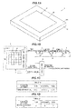
- FIG.1A is a perspective view showing an operating device in the embodiment
- FIG.1B is a block diagram of the operating device
- FIG.1C is a table stored in a discrimination unit
- FIG.1D is a table stored in an alteration unit. It should be noted that a component-to-component ratio is sometimes different from the actual ratio in each drawing of the embodiment.
- An operating device 1 is capable of operating, e.g., an electronic device connected thereto.
- the operating device 1 is configured to detect an operation performed by bringing, e.g., a detection object such as a portion of the body of an operator (e.g., a finger) or a special pen, etc., into contact with or detectably close to an operation surface 20 and to be capable of giving instructions according to the operation to, e.g., move a cursor displayed on an electronic device or to select, drag or drop a displayed icon.
- a detection object such as a portion of the body of an operator (e.g., a finger) or a special pen, etc.
- an operator can operate the connected electronic device by performing an operation on, e.g., the operation surface 20.
- an operation performed by a finger as a detection object will be described.
- the term "contact" used herein includes approach of a finger to the operation surface 20 which is detectable by the operating device 1, unless it is necessary to differently express.
- a touch panel 2 is arranged so that the operation surface 20 is exposed on a surface 100 of a main body 10, as shown in FIG.1 .
- the operating device 1 is generally composed mainly of the touch panel 2 as the detecting portion which outputs a first capacitance as the first detection value in accordance with a distance between a finger and the operation surface 20, a determination unit 3 which determines contact of the finger with the operation surface 20 by comparing the first capacitance acquired from the touch panel 2 and a pre-set first threshold 30, a discrimination unit 4 which, after contact has been determined by the determination unit 3, discriminates on the basis of the first capacitance the amount of sensitivity of the finger contributing to the capacitance as a detection value detected by the touch panel 2, an alteration unit 5 which alters the first threshold 30 to a second threshold 51 on the basis of the amount of sensitivity of the finger discriminated by the discrimination unit 4, and a control unit 6 as the operation detecting portion which detects an operation by the finger by comparing a second capacitance as the second detection value acquired from the touch panel 2 to the second threshold 51 acquired from the alteration unit 5.
- the amount of sensitivity of the finger varies depending on, e.g., a difference in conductivity or dielectric properties of the body of each individual in addition to the contact area of the finger.
- capacitance detected at the time of contact with the operation surface 20 varies with individuals even when the contact area is the same. Therefore, thickness of finger described herein is to take into consideration the amount of sensitivity of the finger, as described later.
- the thickness of finger without considering the amount of sensitivity means, e.g., a cross sectional area of the detection object which is taken in a contact state of the detection object with the operation surface 20 so as to be cut along a plane parallel to the operation surface 20 at a distance from the operation surface 20 which is given when deciding the first threshold 30.
- the thickness of the finger herein is an expression including the amount of sensitivity of the finger, unless otherwise specifically mentioned.
- the touch panel 2 in the present embodiment is, e.g., a capacitive touch sensor from which variation in current, which is caused by an approach of the finger to the operation surface 20 and is inversely proportional to a distance between a sensor wire 21 /a sensor wire 22 and the finger, is output as a detection signal.
- the touch panel 2 is generally composed of sensor wires 21, sensor wires 22 and a touch panel control unit 23.
- the sensor wire 21 and the sensor wire 22 are formed of, e.g., ITO (Indium Tin Oxide).
- the sensor wires 21 and the sensor wires 22 are aligned in a vertical direction and a horizontal direction of the paper plane.
- the horizontal direction of the paper plane of FIG.1B is defined as the x-axis
- the vertical direction is defined as the y-axis
- the upper left of the operation surface 20 of the touch panel 2 is defined as a point of origin.
- This x-y coordinate system is a first coordinate system.
- m sensor wires 21 are aligned at equal intervals. This m is, e.g., a positive integer.
- n sensor wires 22 are aligned at equal intervals. This n is, e.g., a positive integer.
- the sensor wires 21 aligned along the x-axis are electrically insulated from, e.g., the sensor wires 22 aligned along the y-axis.
- the touch panel control unit 23 is configured to sequentially read out capacitances of the sensor wires 21 in the x-axis direction from left to right of the paper plane of FIG.1B and of the sensor wires 22 in the y-axis direction from top to bottom of the paper plane in this order.
- the touch panel control unit 23 is configured to read out capacitance based on a control signal output from the control unit 6.
- the touch panel control unit 23 is configured to output the read-out capacitance of, e.g., each sensor wire 21 to the determination unit 3 and the control unit 6.
- the touch panel 2 may be configured to additionally include, e.g., a display on the opposite side to the operation surface 20 to display images.
- the determination unit 3 has the first threshold 30.
- the determination unit 3 is configured to determine contact of finger by comparing the first capacitance acquired from the touch panel 2 to the first threshold 30.
- the determination unit 3 is configured to, e.g., include the first capacitance, to produce determination information indicating that contact is determined, and to output the determination information to the discrimination unit 4.
- this "contact” includes the approach of the finger to the operation surface 20 to the extent that capacitance reaches the first threshold 30 or more. This is because, for example, when an operator inputs characters to the operation surface 20 by a finger, the finger is not necessarily continuously in contact with the operation surface 20 during performing an operation.
- the first capacitance is, e.g., capacitance of not less than the first threshold 30 among capacitances periodically read out by the touch panel 2 based on a control signal from the below-described control unit 6, i.e., is capacitance when the contact is determined. Then, capacitance output from the touch panel 2 after the contact is determined by the determination unit 3 is output as a second capacitance to the control unit 6. A capacitance after determining the termination of the operation is output to the determination unit 3 and is used for determining the contact.
- the discrimination unit 4 has a table 40 for associating a contact area S of the finger calculated on the basis of the first capacitance with the finger size, and discriminates the finger thickness on the basis of the contact area S and the table 40.
- the contact area S is calculated using a well-known method, e.g., a calculation method using coordinates obtained from the capacitance of not less than first threshold 30. For the calculation of the contact area S, distribution of the amount of sensitivity at the plural sensor wires 21 and the sensor wires 21 is taken into consideration.
- the discrimination unit 4 may be configured such that an average contact area during detection of contact of the finger conducted by the touch panel 2 is defined as the contact area S.
- the determination unit 3 calculates an average of plural contact areas during the period from when the contact of the finger with the operation surface 20 is determined to when the moving away of the finger is determined, and then defines the average as the contact area S.
- the table 40 and a below-described table 50 may be obtained by, e.g., experiments and simulations etc.
- the discrimination unit 4 and the alteration unit 5 are not limited to, e.g., the ones having the configuration using the table 40 and the table 50 and may be configured to derive the second threshold 51, etc., by calculation.
- the table 40 is to associate, e.g., the calculated contact area S of the finger with the finger thickness, as shown in FIG.1C .
- the contact area S is, e.g., not more than a (S ⁇ a)
- it is discriminated that the finger thickness is "thin”.
- the contact area S is, e.g., more than a and less than b (a ⁇ S ⁇ b)
- the contact area S is, e.g., not less than b (b ⁇ S)
- it is discriminated that the finger thickness is "thick".
- a, b and c are more than 0 (0 ⁇ a, b, c).
- a, b and c are determined by, e.g., experiments and simulations using model fingers with respective thicknesses as described above. From the discrimination unit 4, the discrimination results are output as discrimination information to the alteration unit 5.
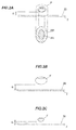
- FIG.2A is a schematic view for explaining sensitivity of the operating device in the embodiment (including a projection view showing a finger F projected on the operation surface)
- FIG.2B is a schematic view for explaining sensitivity in Comparative Example when the finger F is thick
- FIG.2C is a schematic view for explaining sensitivity in Comparative Example when the finger F is thin.
- the alteration unit 5 is configure to alter the first threshold 30 to the second threshold 51 on the basis of the finger thickness discriminated by the discrimination unit 4.
- capacitance is inversely proportional to a distance between the operation surface 20 and the finger F and is proportional to the thickness of the finger F.
- the capacitance is proportional to the thickness of the finger F when the distance from the operation surface 20 is the same. Therefore, the operation may be or may not be detected depending on the thickness of the finger F even when the distance from the operation surface 20 is the same.
- the thickness of the finger F is determined by taking into consideration the amount of sensitivity.
- an area of a projection image 200 of a thick finger F projected on the operation surface 20 is larger than an area of a projection image 201 of a thin finger F, as shown in FIG.2A . Therefore, when a threshold used for determining the contact is fixed, there is a possibility that contact of the thick finger F can be determined at a distance d 1 from the operation surface 20 as shown in Comparative Example of FIG.2B but contact of the thin finger F cannot be determined until a distance d 2 which is shorter than the distance d 1 as shown in Comparative Example of FIG.2C .
- the projection image 200 and the projection image 201 are images of a portion contributing to capacitance projected on the operation surface 20.
- the operating device 1 is thus configured so that the thickness of the finger contributing capacitance detected by the touch panel 2 is discriminated based on the first capacitance, the first threshold 30 is altered according to the discriminated finger thickness and an operation is detected at substantially the same distance d as shown in FIG.2A with any finger thicknesses.
- the finger thickness is calculated by taking into consideration the amount of sensitivity.
- the alteration unit 5 alters the second threshold 51 to "A” based on the table 50 when the discriminated finger thickness is "thin". Meanwhile, the alteration unit 5 alters the second threshold 51 to "B” based on the table 50 when the discriminated finger thickness is "standard”. Furthermore, the alteration unit 5 alters the second threshold 51 to "C” based on the table 50 when the discriminated finger thickness is "thick".
- A, B and C here are, e.g., positive numbers which satisfy a relation ofA ⁇ B ⁇ C.
- the categories of the finger thickness to be discriminated are not limited to the above-mentioned three types and may be less or more. Alternatively, the finger thickness to be discriminated may be calculated according to the contact area.
- the control unit 6 is, e.g., a microcomputer composed of a CPU (Central Processing Unit) performing calculation and processing, etc., of the acquired data according to a stored program, a RAM (Random Access Memory) and a ROM (Read Only Memory) which are semiconductor memories.
- the ROM stores e.g. a program for operation of the control unit 6.
- the RAM is used as, e.g., a storage area for temporarily storing calculation results, etc.
- the control unit 6 has, inside thereof, a means for generating clock signals and is operated based on the clock signals.
- the control unit 6 is configured to detect an operation performed by a finger by comparing the second capacitance acquired from the touch panel 2 to the second threshold 51 acquired from the alteration unit 5.
- control unit 6 is configured to, e.g., calculate coordinates of the portion operated on the operation surface 20 based on the second capacitance of not less than second threshold 51 and to output the coordinates as operation information to the connected electronic device.
- the coordinates are calculated at a predetermined cycle according to the clock signal, in the same manner as the readout of capacitance.
- control unit 6 is configured to generate a control signal at the predetermined cycle and then to output the control signal to the touch panel control unit 23.
- the control unit 6 generates a control signal at a predetermined cycle and then outputs the control signal to the touch panel control unit 23.
- the touch panel control unit 23 reads out the first capacitance based on the acquired control signal (S 1 ) and then outputs the first capacitance to the determination unit 3.
- the determination unit 3 determines presence of contact based on the acquired first capacitance and the first threshold 30. Once the contact of the finger is determined, i.e., when "Yes" is applicable in Step 2 (Yes: S2), the determination unit 3 produces determination information which is then output to the discrimination unit 4.
- the discrimination unit 4 discriminates the finger thickness based on the acquired determination information and the table 40 (S3). Once the finger thickness is discriminated, the discrimination unit 4 subsequently produces discrimination information which is then output to the alteration unit 5.
- the alteration unit 5 alters the first threshold 30 to the second threshold 51 based on the acquired discrimination information and the table 50 and then outputs the second threshold 51 to the control unit 6 (S4).
- the control unit 6 detects an operation by comparing the acquired second threshold 51 to the second capacitance acquired from the touch panel 2 (S5), and then calculates coordinates of the position where the contact is detected. Following this, the control unit 6 produces operation information including information of the calculated coordinates and then outputs the operation information to the electronic device.
- the control unit 6 detects an operation by comparing the capacitance acquired at each cycle to the second threshold 51 and continuously produces and outputs operation information as long as the operation continues. This series of processes is continuously performed during that the operating device 1 is on.
- the operating device 1 in the present embodiment can suppress differences in operational feeling resulting from the amount of sensitivity of the detection object.
- the amount of sensitivity of the finger contributing to the capacitance detected by the touch panel 2 is discriminated based on the first capacitance and a threshold for detecting the operation is altered according to the discriminated amount of sensitivity of the finger. Therefore, in the operating device 1, variation in the distance from the operation surface 20 to detect the operation, which is caused by a difference in the amount of sensitivity of the finger, is suppressed and differences in operational feeling are thus suppressed.
- the operating device 1 includes the table 40 for discriminating the finger thickness based on the contact area S calculated by taking into consideration the amount of sensitivity and the table 50 for setting the second threshold 51 based on the finger thickness. Therefore, as compared to calculation from the capacitance, the load on the control unit 6 is reduced and the processing speed is fast. In addition, the operating device 1 can be manufactured at low cost since it is not necessary to provide a control unit performing sophisticated processing as described above.
- the operating device 1 detects contact and approach to the operation surface 20 based on the second threshold 51 regardless of the finger thickness. Therefore, unlike the device which detects only the contact, characters, etc., written on the operation surface 20 still can be detected even when the finger is off from the operation surface 20 during performing an operation, and detection accuracy of the performed operation is improved.
- This invention can be applied to an operating device in which the operational feeling (detection sensitivity) may vary due to a difference in the amount of sensitivity of a detection object.
Landscapes
- Engineering & Computer Science (AREA)
- General Engineering & Computer Science (AREA)
- Theoretical Computer Science (AREA)
- Human Computer Interaction (AREA)
- Physics & Mathematics (AREA)
- General Physics & Mathematics (AREA)
- Position Input By Displaying (AREA)
Abstract
Description
- An embodiment of this invention relates to an operating device.
- A character input device is known that allows a user to write characters by a finger (see e.g. PTL 1).
- The character input device is provided with a touch panel input means, a sensing means for sensing movement of a finger of an operator performing an operation on the touch panel input means, an extraction means for extracting the movement of the finger of the operator performing the operation on the touch panel input means based on the detection result of the sensing means, and a recognition means for recognizing characters input by operator's handwriting based on a path which is traced by the finger of the operator and is extracted by the extraction means. The character input device determines an operation from e.g. a path of the center point of the shadow of the finger sensed by the sensing means and thus can extract the operation even when the finger thickness is different.
- [PTL 1]
JP-A-H09-245224 - When the operator writes characters on the touch panel input means by a finger, the finger may be sometimes off the touch panel input means during performing an operation. Then, it is difficult for the conventional character input device to sense the path of the finger without continuous contact of the finger and thus the characters may not be recognized correctly. Even if the device is provided with a detection means that can detect the operation by the finger being off an operation surface, a distance to detect the operation may vary, e.g., when using a different finger even if the operator is the same and this may cause differences in operational feeling (detection sensitivity).
- It is an object of the invention to provide an operating device that prevents the occurrence of the differences in operational feeling (detection sensitivity) resulting from a difference in the amount of sensitivity of a detection object.
- According to one embodiment of the invention, an operating device is provided that comprises:
- a detecting portion that outputs a first detection value in accordance with a distance between a detection object and an operation surface;
- a determination unit that determines contact to the operation surface by the detection object by comparing the first detection value acquired from the detecting portion and a pre-set first threshold;
- a discrimination unit that, after contact has been determined by the determination unit, discriminate on the basis of the first detection value the amount of sensitivity of the detection object contributing to the detection value detected by the detecting portion; an alteration unit that alters the first threshold to a second threshold on the basis of the amount of sensitivity of the detection object discriminated by the discrimination unit; and
- an operation detecting portion that detects an operation by the detection object by comparing a second detection value acquired from the detecting portion to the second threshold acquired from the alteration unit.
- According to one embodiment of the invention, an operating device can be provided that prevents the occurrence of the differences in operational feeling (detection sensitivity) resulting from a difference in the amount of sensitivity of a detection object.
-
- [
FIG. 1A ]
FIG.1A is a perspective view showing an operating device in an embodiment. - [
FIG.1B ]
FIG.1B is a block diagram of the operating device. - [
FIG.1C ]
FIG.1C is a table stored in a discrimination unit. - [
FIG.1D ]
FIG.1D is a table stored in an alteration unit. - [
FIG.2A ]
FIG.2A is a schematic view for explaining sensitivity of the operating device in the embodiment (including a projection view showing a finger projected on an operation surface). - [
FIG.2B ]
FIG.2B is a schematic view for explaining sensitivity in Comparative Example when a finger is thick. - [
FIG.2C ]
FIG.2C is a schematic view for explaining sensitivity in Comparative Example when a finger is thin. - [
FIG.3 ]
FIG.3 is a flowchart for explaining an operation of the operating device in the embodiment. - An operating device in the embodiment is provided with a detecting portion which outputs a first detection value in accordance with a distance between a detection object and an operation surface; a determination unit which determines contact to the operation surface by the detection object by comparing the first detection value acquired from the detecting portion and a pre-set first threshold; a discrimination unit which, after contact has been determined by the determination unit, discriminate on the basis of the first detection value the amount of sensitivity of the detection object contributing to the detection value detected by the detecting portion; an alteration unit which alters the first threshold to a second threshold on the basis of the amount of sensitivity of the detection object discriminated by the discrimination unit; and an operation detecting portion which detects an operation by the detection object by comparing a second detection value acquired from the detecting portion to the second threshold acquired from the alteration unit.
-
FIG.1A is a perspective view showing an operating device in the embodiment,FIG.1B is a block diagram of the operating device,FIG.1C is a table stored in a discrimination unit andFIG.1D is a table stored in an alteration unit. It should be noted that a component-to-component ratio is sometimes different from the actual ratio in each drawing of the embodiment. - An
operating device 1 is capable of operating, e.g., an electronic device connected thereto. Theoperating device 1 is configured to detect an operation performed by bringing, e.g., a detection object such as a portion of the body of an operator (e.g., a finger) or a special pen, etc., into contact with or detectably close to anoperation surface 20 and to be capable of giving instructions according to the operation to, e.g., move a cursor displayed on an electronic device or to select, drag or drop a displayed icon. In other words, an operator can operate the connected electronic device by performing an operation on, e.g., theoperation surface 20. In the present embodiment, an operation performed by a finger as a detection object will be described. The term "contact" used herein includes approach of a finger to theoperation surface 20 which is detectable by theoperating device 1, unless it is necessary to differently express. - In the
operating device 1, atouch panel 2 is arranged so that theoperation surface 20 is exposed on asurface 100 of amain body 10, as shown inFIG.1 . - Here, the
operating device 1 is generally composed mainly of thetouch panel 2 as the detecting portion which outputs a first capacitance as the first detection value in accordance with a distance between a finger and theoperation surface 20, adetermination unit 3 which determines contact of the finger with theoperation surface 20 by comparing the first capacitance acquired from thetouch panel 2 and a pre-setfirst threshold 30, adiscrimination unit 4 which, after contact has been determined by thedetermination unit 3, discriminates on the basis of the first capacitance the amount of sensitivity of the finger contributing to the capacitance as a detection value detected by thetouch panel 2, analteration unit 5 which alters thefirst threshold 30 to asecond threshold 51 on the basis of the amount of sensitivity of the finger discriminated by thediscrimination unit 4, and acontrol unit 6 as the operation detecting portion which detects an operation by the finger by comparing a second capacitance as the second detection value acquired from thetouch panel 2 to thesecond threshold 51 acquired from thealteration unit 5. - Here, when the detection object is a finger, the amount of sensitivity of the finger (sensitivity to detect capacitance) varies depending on, e.g., a difference in conductivity or dielectric properties of the body of each individual in addition to the contact area of the finger. In other words, capacitance detected at the time of contact with the
operation surface 20 varies with individuals even when the contact area is the same. Therefore, thickness of finger described herein is to take into consideration the amount of sensitivity of the finger, as described later. Here, the thickness of finger without considering the amount of sensitivity means, e.g., a cross sectional area of the detection object which is taken in a contact state of the detection object with theoperation surface 20 so as to be cut along a plane parallel to theoperation surface 20 at a distance from theoperation surface 20 which is given when deciding thefirst threshold 30. The thickness of the finger herein is an expression including the amount of sensitivity of the finger, unless otherwise specifically mentioned. - The
touch panel 2 in the present embodiment is, e.g., a capacitive touch sensor from which variation in current, which is caused by an approach of the finger to theoperation surface 20 and is inversely proportional to a distance between asensor wire 21/asensor wire 22 and the finger, is output as a detection signal. - As shown in
FIG.1B , thetouch panel 2 is generally composed ofsensor wires 21,sensor wires 22 and a touchpanel control unit 23. - As shown in
FIG.1B , thesensor wires 21 and thesensor wires 22 are aligned in a vertical direction and a horizontal direction of the paper plane. In the present embodiment, the horizontal direction of the paper plane ofFIG.1B is defined as the x-axis, the vertical direction is defined as the y-axis and the upper left of theoperation surface 20 of thetouch panel 2 is defined as a point of origin. This x-y coordinate system is a first coordinate system. - In the x-axis direction, for example,
m sensor wires 21 are aligned at equal intervals. This m is, e.g., a positive integer. - In the y-axis direction, for example,
n sensor wires 22 are aligned at equal intervals. This n is, e.g., a positive integer. - The
sensor wires 21 aligned along the x-axis are electrically insulated from, e.g., thesensor wires 22 aligned along the y-axis. - The touch
panel control unit 23 is configured to sequentially read out capacitances of thesensor wires 21 in the x-axis direction from left to right of the paper plane ofFIG.1B and of thesensor wires 22 in the y-axis direction from top to bottom of the paper plane in this order. The touchpanel control unit 23 is configured to read out capacitance based on a control signal output from thecontrol unit 6. - In addition, the touch
panel control unit 23 is configured to output the read-out capacitance of, e.g., eachsensor wire 21 to thedetermination unit 3 and thecontrol unit 6. - The
touch panel 2 may be configured to additionally include, e.g., a display on the opposite side to theoperation surface 20 to display images. - As shown in
FIG.1B , thedetermination unit 3 has thefirst threshold 30. Thedetermination unit 3 is configured to determine contact of finger by comparing the first capacitance acquired from thetouch panel 2 to thefirst threshold 30. Thedetermination unit 3 is configured to, e.g., include the first capacitance, to produce determination information indicating that contact is determined, and to output the determination information to thediscrimination unit 4. - As described above, this "contact" includes the approach of the finger to the
operation surface 20 to the extent that capacitance reaches thefirst threshold 30 or more. This is because, for example, when an operator inputs characters to theoperation surface 20 by a finger, the finger is not necessarily continuously in contact with theoperation surface 20 during performing an operation. - The first capacitance is, e.g., capacitance of not less than the
first threshold 30 among capacitances periodically read out by thetouch panel 2 based on a control signal from the below-describedcontrol unit 6, i.e., is capacitance when the contact is determined. Then, capacitance output from thetouch panel 2 after the contact is determined by thedetermination unit 3 is output as a second capacitance to thecontrol unit 6. A capacitance after determining the termination of the operation is output to thedetermination unit 3 and is used for determining the contact. - As shown in
FIG.1C , thediscrimination unit 4 has a table 40 for associating a contact area S of the finger calculated on the basis of the first capacitance with the finger size, and discriminates the finger thickness on the basis of the contact area S and the table 40. The contact area S is calculated using a well-known method, e.g., a calculation method using coordinates obtained from the capacitance of not less thanfirst threshold 30. For the calculation of the contact area S, distribution of the amount of sensitivity at theplural sensor wires 21 and thesensor wires 21 is taken into consideration. - Alternatively, the
discrimination unit 4 may be configured such that an average contact area during detection of contact of the finger conducted by thetouch panel 2 is defined as the contact area S. In this case, thedetermination unit 3 calculates an average of plural contact areas during the period from when the contact of the finger with theoperation surface 20 is determined to when the moving away of the finger is determined, and then defines the average as the contact area S. - The table 40 and a below-described table 50 may be obtained by, e.g., experiments and simulations etc. The
discrimination unit 4 and thealteration unit 5 are not limited to, e.g., the ones having the configuration using the table 40 and the table 50 and may be configured to derive thesecond threshold 51, etc., by calculation. - The table 40 is to associate, e.g., the calculated contact area S of the finger with the finger thickness, as shown in
FIG.1C . When the contact area S is, e.g., not more than a (S≤a), it is discriminated that the finger thickness is "thin". When the contact area S is, e.g., more than a and less than b (a<S<b), it is discriminated that the finger thickness is "standard". When the contact area S is, e.g., not less than b (b≤S), it is discriminated that the finger thickness is "thick". Here, a, b and c are more than 0 (0 < a, b, c). a, b and c are determined by, e.g., experiments and simulations using model fingers with respective thicknesses as described above. From thediscrimination unit 4, the discrimination results are output as discrimination information to thealteration unit 5. -
FIG.2A is a schematic view for explaining sensitivity of the operating device in the embodiment (including a projection view showing a finger F projected on the operation surface),FIG.2B is a schematic view for explaining sensitivity in Comparative Example when the finger F is thick, andFIG.2C is a schematic view for explaining sensitivity in Comparative Example when the finger F is thin. - The
alteration unit 5 is configure to alter thefirst threshold 30 to thesecond threshold 51 on the basis of the finger thickness discriminated by thediscrimination unit 4. - Here, capacitance is inversely proportional to a distance between the
operation surface 20 and the finger F and is proportional to the thickness of the finger F. In other words, the capacitance is proportional to the thickness of the finger F when the distance from theoperation surface 20 is the same. Therefore, the operation may be or may not be detected depending on the thickness of the finger F even when the distance from theoperation surface 20 is the same. The thickness of the finger F is determined by taking into consideration the amount of sensitivity. - In detail, when a distance d from the
operation surface 20 to the finger F is the same, an area of aprojection image 200 of a thick finger F projected on theoperation surface 20 is larger than an area of aprojection image 201 of a thin finger F, as shown inFIG.2A . Therefore, when a threshold used for determining the contact is fixed, there is a possibility that contact of the thick finger F can be determined at a distance d1 from theoperation surface 20 as shown in Comparative Example ofFIG.2B but contact of the thin finger F cannot be determined until a distance d2 which is shorter than the distance d1 as shown in Comparative Example ofFIG.2C . Theprojection image 200 and theprojection image 201 are images of a portion contributing to capacitance projected on theoperation surface 20. - Therefore, when a distance allowing detection of the operation is different depending on the thickness of the finger F as shown in
FIGS.2B and 2C , operational feeling varies by using a different finger even if the operator is the same, hence, poor operational feeling. - The operating
device 1 is thus configured so that the thickness of the finger contributing capacitance detected by thetouch panel 2 is discriminated based on the first capacitance, thefirst threshold 30 is altered according to the discriminated finger thickness and an operation is detected at substantially the same distance d as shown inFIG.2A with any finger thicknesses. The finger thickness is calculated by taking into consideration the amount of sensitivity. - The
alteration unit 5 alters thesecond threshold 51 to "A" based on the table 50 when the discriminated finger thickness is "thin". Meanwhile, thealteration unit 5 alters thesecond threshold 51 to "B" based on the table 50 when the discriminated finger thickness is "standard". Furthermore, thealteration unit 5 alters thesecond threshold 51 to "C" based on the table 50 when the discriminated finger thickness is "thick". A, B and C here are, e.g., positive numbers which satisfy a relation ofA<B<C. - The categories of the finger thickness to be discriminated are not limited to the above-mentioned three types and may be less or more. Alternatively, the finger thickness to be discriminated may be calculated according to the contact area.
- The
control unit 6 is, e.g., a microcomputer composed of a CPU (Central Processing Unit) performing calculation and processing, etc., of the acquired data according to a stored program, a RAM (Random Access Memory) and a ROM (Read Only Memory) which are semiconductor memories. The ROM stores e.g. a program for operation of thecontrol unit 6. The RAM is used as, e.g., a storage area for temporarily storing calculation results, etc. In addition, thecontrol unit 6 has, inside thereof, a means for generating clock signals and is operated based on the clock signals. - The
control unit 6 is configured to detect an operation performed by a finger by comparing the second capacitance acquired from thetouch panel 2 to thesecond threshold 51 acquired from thealteration unit 5. - In addition, the
control unit 6 is configured to, e.g., calculate coordinates of the portion operated on theoperation surface 20 based on the second capacitance of not less thansecond threshold 51 and to output the coordinates as operation information to the connected electronic device. The coordinates are calculated at a predetermined cycle according to the clock signal, in the same manner as the readout of capacitance. In addition, thecontrol unit 6 is configured to generate a control signal at the predetermined cycle and then to output the control signal to the touchpanel control unit 23. - The operation of the
operating device 1 in the embodiment will be described below in accordance with the flowchart ofFIG.3 while also referring to each drawing. - The
control unit 6 generates a control signal at a predetermined cycle and then outputs the control signal to the touchpanel control unit 23. The touchpanel control unit 23 reads out the first capacitance based on the acquired control signal (S1) and then outputs the first capacitance to thedetermination unit 3. - The
determination unit 3 determines presence of contact based on the acquired first capacitance and thefirst threshold 30. Once the contact of the finger is determined, i.e., when "Yes" is applicable in Step 2 (Yes: S2), thedetermination unit 3 produces determination information which is then output to thediscrimination unit 4. - The
discrimination unit 4 discriminates the finger thickness based on the acquired determination information and the table 40 (S3). Once the finger thickness is discriminated, thediscrimination unit 4 subsequently produces discrimination information which is then output to thealteration unit 5. - The
alteration unit 5 alters thefirst threshold 30 to thesecond threshold 51 based on the acquired discrimination information and the table 50 and then outputs thesecond threshold 51 to the control unit 6 (S4). - The
control unit 6 detects an operation by comparing the acquiredsecond threshold 51 to the second capacitance acquired from the touch panel 2 (S5), and then calculates coordinates of the position where the contact is detected. Following this, thecontrol unit 6 produces operation information including information of the calculated coordinates and then outputs the operation information to the electronic device. Thecontrol unit 6 detects an operation by comparing the capacitance acquired at each cycle to thesecond threshold 51 and continuously produces and outputs operation information as long as the operation continues. This series of processes is continuously performed during that theoperating device 1 is on. - The operating
device 1 in the present embodiment can suppress differences in operational feeling resulting from the amount of sensitivity of the detection object. In theoperating device 1, the amount of sensitivity of the finger contributing to the capacitance detected by thetouch panel 2 is discriminated based on the first capacitance and a threshold for detecting the operation is altered according to the discriminated amount of sensitivity of the finger. Therefore, in theoperating device 1, variation in the distance from theoperation surface 20 to detect the operation, which is caused by a difference in the amount of sensitivity of the finger, is suppressed and differences in operational feeling are thus suppressed. - The operating
device 1 includes the table 40 for discriminating the finger thickness based on the contact area S calculated by taking into consideration the amount of sensitivity and the table 50 for setting thesecond threshold 51 based on the finger thickness. Therefore, as compared to calculation from the capacitance, the load on thecontrol unit 6 is reduced and the processing speed is fast. In addition, the operatingdevice 1 can be manufactured at low cost since it is not necessary to provide a control unit performing sophisticated processing as described above. - The operating
device 1 detects contact and approach to theoperation surface 20 based on thesecond threshold 51 regardless of the finger thickness. Therefore, unlike the device which detects only the contact, characters, etc., written on theoperation surface 20 still can be detected even when the finger is off from theoperation surface 20 during performing an operation, and detection accuracy of the performed operation is improved. - Although some embodiments of the invention have been described above, these embodiments are merely an example and the invention according to claims is not to be limited thereto. These new embodiments can be implemented in various other forms, and various omissions, substitutions and changes, etc., can be made without departing from the gist of the invention. In addition, all combinations of the features described in these embodiments are not necessary to solve the problem of the invention. Further, these embodiments are included within the scope and gist of the invention and also within the invention described in the claims and the range of equivalency.
- This invention can be applied to an operating device in which the operational feeling (detection sensitivity) may vary due to a difference in the amount of sensitivity of a detection object.
-
- 1
- Operating device
- 2
- Touch panel
- 3
- Determination unit
- 4
- Discrimination unit
- 5
- Alteration unit
- 6
- Control unit
- 10
- Main body
- 20
- Operation surface
- 21
- Sensor wire
- 22
- Sensor wire
- 23
- Touch panel control unit
- 30
- First threshold
- 40
- Table
- 50
- Table
- 51
- Second threshold
- 100
- Surface
- 200
- Projection image
- 201
- Projection image
Claims (4)
- An operating device, comprising:a detecting portion that outputs a first detection value in accordance with a distance between a detection object and an operation surface;a determination unit that determines contact to the operation surface by the detection object by comparing the first detection value acquired from the detecting portion and a pre-set first threshold;a discrimination unit that, after contact has been determined by the determination unit, discriminate on the basis of the first detection value the amount of sensitivity of the detection object contributing to the detection value detected by the detecting portion;an alteration unit that alters the first threshold to a second threshold on the basis of the amount of sensitivity of the detection object discriminated by the discrimination unit; andan operation detecting portion that detects an operation by the detection object by comparing a second detection value acquired from the detecting portion to the second threshold acquired from the alteration unit.
- The operating device according to claim 1, wherein the discrimination unit comprises a table for associating a contact area of the detection object calculated on the basis of the first detection value with the amount of sensitivity of the detection object, and discriminates the amount of sensitivity of the detection object on the basis of the contact area and the table.
- The operating device according to claim 1 or 2, wherein the operation detecting portion calculates coordinates based on contact or approach of the detection object when the second detection value is not less than the second threshold.
- The operating device according to claim 2, wherein, in the discrimination unit, an average value of contact area during detection of contact of the detection object conducted by the detecting portion is defined as the contact area of the detection object.
Applications Claiming Priority (2)
| Application Number | Priority Date | Filing Date | Title |
|---|---|---|---|
| JP2012142852A JP6005417B2 (en) | 2012-06-26 | 2012-06-26 | Operating device |
| PCT/JP2012/083495 WO2014002316A1 (en) | 2012-06-26 | 2012-12-25 | Operation device |
Publications (2)
| Publication Number | Publication Date |
|---|---|
| EP2866126A1 true EP2866126A1 (en) | 2015-04-29 |
| EP2866126A4 EP2866126A4 (en) | 2015-12-02 |
Family
ID=49782528
Family Applications (1)
| Application Number | Title | Priority Date | Filing Date |
|---|---|---|---|
| EP12879603.4A Withdrawn EP2866126A4 (en) | 2012-06-26 | 2012-12-25 | ACTUATING DEVICE |
Country Status (6)
| Country | Link |
|---|---|
| US (1) | US9436383B2 (en) |
| EP (1) | EP2866126A4 (en) |
| JP (1) | JP6005417B2 (en) |
| CN (1) | CN104364743B (en) |
| TW (1) | TWI550503B (en) |
| WO (1) | WO2014002316A1 (en) |
Families Citing this family (11)
| Publication number | Priority date | Publication date | Assignee | Title |
|---|---|---|---|---|
| JP1511201S (en) * | 2014-03-10 | 2014-11-10 | ||
| TW201735540A (en) * | 2016-03-25 | 2017-10-01 | 松下知識產權經營股份有限公司 | Operation switch using electrostatic capacitance sensor |
| WO2019016875A1 (en) * | 2017-07-19 | 2019-01-24 | 三菱電機株式会社 | Touch operation determination device and method for determining validity of touch operation |
| CN111194434B (en) * | 2017-10-11 | 2024-01-30 | 三菱电机株式会社 | Operation input device, information processing system, and operation determination method |
| DE112017008192T5 (en) * | 2017-12-14 | 2020-07-30 | Mitsubishi Electric Corporation | Operator support device, touch panel device and touch panel input system |
| EP3821198A4 (en) * | 2018-07-12 | 2022-07-20 | Crosman Corporation | ELECTROMAGNETIC RADIATION-BASED ACTIVATION OF DETERRENT DEVICE ACCESSORY |
| JP7155920B2 (en) * | 2018-11-16 | 2022-10-19 | 株式会社アイシン | steering device |
| CN113950730B (en) * | 2019-06-28 | 2025-07-25 | 阿尔卑斯阿尔派株式会社 | Input device |
| JP7317730B2 (en) * | 2020-01-16 | 2023-07-31 | ヤフー株式会社 | Information processing device, information processing method and information processing program |
| KR20230099797A (en) | 2021-12-28 | 2023-07-05 | 주식회사 엘엑스세미콘 | Touch control circuit and display device including the same |
| WO2025053380A1 (en) * | 2023-09-08 | 2025-03-13 | 삼성전자 주식회사 | Electronic device for measuring size of object and method for operating same |
Family Cites Families (10)
| Publication number | Priority date | Publication date | Assignee | Title |
|---|---|---|---|---|
| JP3842328B2 (en) | 1996-03-08 | 2006-11-08 | 株式会社東芝 | Touch panel type input device |
| TW200611287A (en) * | 2004-09-24 | 2006-04-01 | Holtek Semiconductor Inc | Capacitance induction device |
| US7847789B2 (en) * | 2004-11-23 | 2010-12-07 | Microsoft Corporation | Reducing accidental touch-sensitive device activation |
| JP4377343B2 (en) * | 2005-01-31 | 2009-12-02 | 株式会社東海理化電機製作所 | Touch operation input device |
| JP2007027034A (en) * | 2005-07-21 | 2007-02-01 | Calsonic Kansei Corp | Electrostatic capacity type touch switch |
| TWM364242U (en) * | 2008-12-12 | 2009-09-01 | Yuan Mao Technology Co Ltd | Touch pad for variety of sensing |
| WO2010089980A1 (en) | 2009-02-06 | 2010-08-12 | パナソニック株式会社 | Image display device |
| JP5157969B2 (en) | 2009-03-09 | 2013-03-06 | ソニー株式会社 | Information processing apparatus, threshold setting method and program thereof |
| US20110248948A1 (en) * | 2010-04-08 | 2011-10-13 | Research In Motion Limited | Touch-sensitive device and method of control |
| JP5839173B2 (en) * | 2010-10-14 | 2016-01-06 | Nltテクノロジー株式会社 | Touch sensor device and electronic device |
-
2012
- 2012-06-26 JP JP2012142852A patent/JP6005417B2/en not_active Expired - Fee Related
- 2012-12-25 US US14/409,892 patent/US9436383B2/en not_active Expired - Fee Related
- 2012-12-25 WO PCT/JP2012/083495 patent/WO2014002316A1/en not_active Ceased
- 2012-12-25 CN CN201280073495.XA patent/CN104364743B/en not_active Expired - Fee Related
- 2012-12-25 EP EP12879603.4A patent/EP2866126A4/en not_active Withdrawn
-
2013
- 2013-01-18 TW TW102102018A patent/TWI550503B/en not_active IP Right Cessation
Also Published As
| Publication number | Publication date |
|---|---|
| US9436383B2 (en) | 2016-09-06 |
| CN104364743B (en) | 2018-05-01 |
| WO2014002316A1 (en) | 2014-01-03 |
| CN104364743A (en) | 2015-02-18 |
| TWI550503B (en) | 2016-09-21 |
| JP6005417B2 (en) | 2016-10-12 |
| TW201401161A (en) | 2014-01-01 |
| US20150227310A1 (en) | 2015-08-13 |
| EP2866126A4 (en) | 2015-12-02 |
| JP2014006766A (en) | 2014-01-16 |
Similar Documents
| Publication | Publication Date | Title |
|---|---|---|
| US9436383B2 (en) | Operating device | |
| US9395852B2 (en) | Method for distinguishing between edge swipe gestures that enter a touch sensor from an edge and other similar but non-edge swipe actions | |
| EP3065033B1 (en) | Touch screen sensing method, device and computer program product | |
| US12067187B2 (en) | Position detection circuit and position detection method | |
| WO2019119361A1 (en) | Method for avoiding mistakenly touching edge, touch control device and storage medium | |
| CN103324964B (en) | Identity identification system and method | |
| US20130044076A1 (en) | Touch sensing methods and devices therefore | |
| JP6278889B2 (en) | INPUT DEVICE, ITS CONTROL METHOD, AND PROGRAM | |
| US10678381B2 (en) | Determining handedness on multi-element capacitive devices | |
| KR20140077000A (en) | Touch panel and dizitizer pen position sensing method for dizitizer pen the same | |
| US20150193068A1 (en) | Method and apparatus for sensing touch pressure of touch panel and touch sensing apparatus using the same | |
| JP2014186530A (en) | Input device and portable terminal device | |
| EP3738023A1 (en) | Computer device having variable display output based on user input with variable time and/or pressure patterns | |
| JP2010231480A (en) | Handwriting processing apparatus, program, and method | |
| CN101430627B (en) | Touch detection method of photosensitive touch panel and touch electronic device using same | |
| TW201401155A (en) | Operation device | |
| US11157117B2 (en) | Pseudo push determination method in touch sensor without force sensor | |
| CN110134269B (en) | Electronic device and associated method for verifying multi-finger touch detection via annular touch islands | |
| CN106560766A (en) | Non-contact gesture judgment method and device | |
| CN122044388A (en) | Touch recognition method, touch recognition device, electronic equipment and computer readable medium | |
| JP2019145069A (en) | Position detection circuit and position detection method |
Legal Events
| Date | Code | Title | Description |
|---|---|---|---|
| PUAI | Public reference made under article 153(3) epc to a published international application that has entered the european phase |
Free format text: ORIGINAL CODE: 0009012 |
|
| 17P | Request for examination filed |
Effective date: 20150126 |
|
| AK | Designated contracting states |
Kind code of ref document: A1 Designated state(s): AL AT BE BG CH CY CZ DE DK EE ES FI FR GB GR HR HU IE IS IT LI LT LU LV MC MK MT NL NO PL PT RO RS SE SI SK SM TR |
|
| AX | Request for extension of the european patent |
Extension state: BA ME |
|
| DAX | Request for extension of the european patent (deleted) | ||
| RA4 | Supplementary search report drawn up and despatched (corrected) |
Effective date: 20151104 |
|
| RIC1 | Information provided on ipc code assigned before grant |
Ipc: G06F 3/041 20060101ALI20151029BHEP Ipc: G06F 3/044 20060101AFI20151029BHEP |
|
| 17Q | First examination report despatched |
Effective date: 20180320 |
|
| GRAP | Despatch of communication of intention to grant a patent |
Free format text: ORIGINAL CODE: EPIDOSNIGR1 |
|
| RIC1 | Information provided on ipc code assigned before grant |
Ipc: G06F 3/041 20060101AFI20180724BHEP Ipc: G06F 3/0488 20130101ALI20180724BHEP Ipc: G06F 3/044 20060101ALI20180724BHEP |
|
| INTG | Intention to grant announced |
Effective date: 20180827 |
|
| STAA | Information on the status of an ep patent application or granted ep patent |
Free format text: STATUS: THE APPLICATION IS DEEMED TO BE WITHDRAWN |
|
| 18D | Application deemed to be withdrawn |
Effective date: 20190108 |