EP2865844A2 - Bohrlochzonen-Flussregelsystem - Google Patents
Bohrlochzonen-Flussregelsystem Download PDFInfo
- Publication number
- EP2865844A2 EP2865844A2 EP20140189963 EP14189963A EP2865844A2 EP 2865844 A2 EP2865844 A2 EP 2865844A2 EP 20140189963 EP20140189963 EP 20140189963 EP 14189963 A EP14189963 A EP 14189963A EP 2865844 A2 EP2865844 A2 EP 2865844A2
- Authority
- EP
- European Patent Office
- Prior art keywords
- piston
- control
- manifold
- hydraulic
- control lines
- Prior art date
- Legal status (The legal status is an assumption and is not a legal conclusion. Google has not performed a legal analysis and makes no representation as to the accuracy of the status listed.)
- Withdrawn
Links
- 238000000034 method Methods 0.000 claims abstract description 18
- 239000012530 fluid Substances 0.000 claims description 48
- 238000004891 communication Methods 0.000 claims description 18
- 230000037361 pathway Effects 0.000 claims description 8
- 230000004044 response Effects 0.000 claims description 4
- 238000003825 pressing Methods 0.000 claims description 3
- 238000013022 venting Methods 0.000 claims 2
- 238000004519 manufacturing process Methods 0.000 description 7
- 230000007246 mechanism Effects 0.000 description 6
- 238000013461 design Methods 0.000 description 4
- 238000002347 injection Methods 0.000 description 2
- 239000007924 injection Substances 0.000 description 2
- 238000012986 modification Methods 0.000 description 2
- 230000004048 modification Effects 0.000 description 2
- 230000008569 process Effects 0.000 description 2
- 230000004075 alteration Effects 0.000 description 1
- 230000015572 biosynthetic process Effects 0.000 description 1
- 230000000903 blocking effect Effects 0.000 description 1
- 239000010419 fine particle Substances 0.000 description 1
- 230000007257 malfunction Effects 0.000 description 1
- 238000012544 monitoring process Methods 0.000 description 1
- 238000006467 substitution reaction Methods 0.000 description 1
- 238000012546 transfer Methods 0.000 description 1
- XLYOFNOQVPJJNP-UHFFFAOYSA-N water Substances O XLYOFNOQVPJJNP-UHFFFAOYSA-N 0.000 description 1
Images



Classifications
-
- F—MECHANICAL ENGINEERING; LIGHTING; HEATING; WEAPONS; BLASTING
- F04—POSITIVE - DISPLACEMENT MACHINES FOR LIQUIDS; PUMPS FOR LIQUIDS OR ELASTIC FLUIDS
- F04B—POSITIVE-DISPLACEMENT MACHINES FOR LIQUIDS; PUMPS
- F04B47/00—Pumps or pumping installations specially adapted for raising fluids from great depths, e.g. well pumps
-
- E—FIXED CONSTRUCTIONS
- E21—EARTH OR ROCK DRILLING; MINING
- E21B—EARTH OR ROCK DRILLING; OBTAINING OIL, GAS, WATER, SOLUBLE OR MELTABLE MATERIALS OR A SLURRY OF MINERALS FROM WELLS
- E21B34/00—Valve arrangements for boreholes or wells
- E21B34/06—Valve arrangements for boreholes or wells in wells
- E21B34/10—Valve arrangements for boreholes or wells in wells operated by control fluid supplied from outside the borehole
-
- E—FIXED CONSTRUCTIONS
- E21—EARTH OR ROCK DRILLING; MINING
- E21B—EARTH OR ROCK DRILLING; OBTAINING OIL, GAS, WATER, SOLUBLE OR MELTABLE MATERIALS OR A SLURRY OF MINERALS FROM WELLS
- E21B43/00—Methods or apparatus for obtaining oil, gas, water, soluble or meltable materials or a slurry of minerals from wells
- E21B43/12—Methods or apparatus for controlling the flow of the obtained fluid to or in wells
-
- E—FIXED CONSTRUCTIONS
- E21—EARTH OR ROCK DRILLING; MINING
- E21B—EARTH OR ROCK DRILLING; OBTAINING OIL, GAS, WATER, SOLUBLE OR MELTABLE MATERIALS OR A SLURRY OF MINERALS FROM WELLS
- E21B43/00—Methods or apparatus for obtaining oil, gas, water, soluble or meltable materials or a slurry of minerals from wells
- E21B43/14—Obtaining from a multiple-zone well
-
- E—FIXED CONSTRUCTIONS
- E21—EARTH OR ROCK DRILLING; MINING
- E21B—EARTH OR ROCK DRILLING; OBTAINING OIL, GAS, WATER, SOLUBLE OR MELTABLE MATERIALS OR A SLURRY OF MINERALS FROM WELLS
- E21B2200/00—Special features related to earth drilling for obtaining oil, gas or water
- E21B2200/02—Down-hole chokes or valves for variably regulating fluid flow
Definitions
- the present invention relates generally to operations performed in conjunction with downhole wells.
- Intelligent wells include downhole remote flow-control devices used to open, close or regulate flow from and to multiple zones without the need for well intervention. Furthermore, intelligent wells are usually complemented by downhole permanent monitoring systems which provide valuable information used in the decision making process for the control of production or injection. All these systems require multiple control lines and cables to link the downhole tools to the associated surface equipment which serves as the interface between the operator and the system.
- the flow control devices can be either on/off or multi-position valves and can have either balanced piston or spring return type actuators.
- balanced piston design two control lines are used for the operation of each valve, with each control line ported to either side of the piston ("open" and "close” ports). Applying hydraulic fluid pressure on one control line while the other is vented moves the valve in one direction with movement of the valve in an opposite direction accomplished by inverting the operation.
- spring return design the valve operates with only one control line. Applying pressure to the single control line moves the valve in one direction, and, when this pressure is bled off, a mechanical or pneumatic spring moves the valve in the opposite direction.
- a method of actuating a well tool includes applying hydraulic pressure through a first control line to a set input of a manifold thereby opening a communication path for a fire input of the manifold. Applying hydraulic pressure through a second control line to the fire input while holding pressure on the set input establishes flow pathways for a third control line to a first side of a hydraulic operated element and a fourth control line to a second side of the hydraulic operated element. Further, applying hydraulic pressure through at least one of the third and fourth control lines actuates the well tool.
- a system for actuating well tools includes four hydraulic control lines and at least eight of the well tools.
- the system also includes zone control manifolds deployed downhole. The manifolds control which of the tools is selected with two of the control lines and independent functioning of a selected one of the tools with two of the control lines in response to hydraulic pressure supplied to the four hydraulic control lines.
- a manifold for actuating a well tool includes a first piston for selective passage of fluid from a first control line when fluid pressure is not applied to a second control line.
- the manifold includes a second piston for selective passage of fluid from the second control line when fluid pressure from the first control line is passed through the first piston and held to operate the second piston.
- a third piston actuates by fluid pressure from the second control line passed through the second piston for movement of the third piston from having fluid communication blocked to the tool to having flow pathways established for a third control line to a first side of a hydraulic operated element of the tool and a fourth control line to a second side of the hydraulic operated element.
- Methods and systems operate multiple downhole tools in wells based on hydraulic pressures supplied in control lines.
- the methods and systems pair each of the tools with a manifold enabling selective actuation of each of the tools from a remote location.
- Some embodiments include between three and twelve manifold and tool pairs configured for control independent from one another with four of the control lines.
- FIG. 1 shows eight zones 20, 22, 24, 26, 28, 30, 32, 34 for downhole flow control intersecting a casing string.
- the following description assumes that it is desired to produce fluids to the earth's surface from one or more of the zones 20, 22, 24, 26, 28, 30, 32, 34 via a production string 14.
- principles of the present invention are not limited to production wells, production from multiple zones or any of specific details described herein.
- embodiments of the invention may be used in injection wells where fluid flow into a formation is to be controlled or methods where an aspect of the well other than fluid flow is to be controlled.
- the description of the present method and system is an example of the wide variety of uses for the principles of the present invention.
- the production string 14 as depicted in FIG. 1 includes eight zone control manifolds 40, 42, 44, 46, 48, 50, 52, 54.
- the production string 14 also includes production packers 60, 62, 64, 66, 68, 70, 72, 74 for isolating the zones from one another.
- Four hydraulic control lines (also referred to as first, second, third and fourth hydraulic lines) 101, 102, 103, 104 send signals to the zone control manifolds 40, 42, 44, 46, 48, 50, 52, 54 to operate respective downhole control valves 80, 82, 84, 86, 88, 90, 92, 94.
- the four hydraulic control lines 101, 102, 103, 104 with manifold designs described herein provide independent control of up to twelve tools even though only eight of the valves 80, 82, 84, 86, 88, 90, 92, 94 are shown by example. If desired, one or more tools may operate together (i.e., not independent of one another) by having alike control line inputs and thereby enable control of more than twelve tools. In some embodiments, the four hydraulic lines 101, 102, 103, 104 control at least four tools, or at least eight tools, independent of one another.
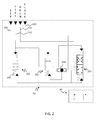
- FIG. 2 illustrates the manifold 40 associated with the downhole control valve 80 and in a deactivated state.
- the manifold 40 includes a first piston 201, a second piston 202 and a third piston 203, which are in fluid communication with the four hydraulic lines 101, 102, 103, 104.
- Outputs of the third piston 203 provide fluid communication for actuation of the valve 80 with a hydraulic operated element of the valve 80 represented for illustration purposes as a schematic valve piston.
- the four hydraulic control lines 101, 102, 103, 104 couple to a "set” input, a “fire” input, an "open” input and a “close” input into each of the manifolds 40, 42, 44, 46, 48, 50, 52, 54. While the manifolds 40, 42, 44, 46, 48, 50, 52, 54 with these inputs may all be configured alike, the control lines 101, 102, 103, 104 in fluid communication with these inputs differ for each of the manifolds 40, 42, 44, 46, 48, 50, 52, 54 to enable the independent control of individual tools.
- the first hydraulic line 101 couples to the set input.
- the second hydraulic line 102 couples to the fire input of the manifold 40.
- the third hydraulic line 103 and the fourth hydraulic line 104 provide hydraulic pressure through the manifold 40 to operate the valve 80 and are thus the open and close inputs.
- a biasing member may provide return movement of the valve 80 instead of pressure supplied through one of the control lines 101, 102, 103, 104.
- Biasing mechanisms such as a spring 206 for the first piston 201, urge the pistons 201, 202, 203 to positions as in the deactivated state.
- the biasing mechanisms facilitate resetting of the pistons 201, 202, 203 after operation of the valve 80.
- Force supplied by the biasing mechanisms may be less than pressure supplied through the hydraulic lines 101, 102, 103, 104.
- the biasing mechanisms also may reset any of the pistons 201, 202, 203 due to differential force created when combined with hydraulic pressure from one of the control lines 101, 102, 103, 104 even when fluid pressure from another one of the control lines 101, 102, 103, 104 is acting in operational opposition on one of the pistons 201, 202, 203.
- Supply sequence for fluid pressure to the control lines 101, 102, 103, 104 determines based on functioning of the pistons 201, 202, 203 whether the manifold 40 is activated to control the valve 80.
- the first piston 201 permits the flow from the first hydraulic line 101 to an operator of the second piston 202. Operation starts by supplying fluid pressure to the first hydraulic line 101.
- FIG. 3 shows the manifold 40 in a set state after the pressure is supplied through the first hydraulic line 101.
- the pressure supplied to the operator of the second piston 202 shifts the second piston 202 from blocking communication between the second hydraulic line 102 and an operator of the third piston 203 to providing a flow path for the second hydraulic line 102 to the operator of the third piston 203.
- the sequence for the manifold 40 to be selected next requires supplying pressure to the second hydraulic line 102 while pressure is supplied through the first hydraulic line 101.
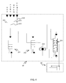
- FIG. 4 illustrates the manifold 40 in a fire state after the second hydraulic line 102 is pressurized.
- the fluid pressure in the second hydraulic line 102 acts on an operator for the first piston 201 shifting the first piston 201 and closing the flow path of the first hydraulic line 101 to the operator of the second piston 202. Since this closing occurs with pressure supplied in the first hydraulic line 101, trapped pressure continues to actuate the second piston 202 against force of the biasing mechanism.
- the pressure in the second hydraulic line 102 also passes through the flow path opened within the second piston 202 to the operator of the third piston 203 for shifting the third piston 203.
- the third piston 203 remains biased to provide a fluid path across the hydraulic operated element of the valve 80 and a fluid path connecting the fourth control line 104 to counteracting sides of the first and third pistons 201, 203 to provide a drain for fluid during movement of the pistons 201, 203.
- the shifting of the third piston 203 to the fire state places the third hydraulic line 103 in fluid communication with a first side of the hydraulic operated element of the valve 80 and the fourth hydraulic line 104 in fluid communication with a second side of the hydraulic operated element of the valve 80 to provide opposing forces to the valve 80 and closes all other fluid pathways through the third piston 203.
- FIG. 5 shows the manifold 40 in an operational state with the valve 80 having moved position, e.g., from closed to open.
- the valve 80 moves as a result of supplying pressure to the third hydraulic line 103 since the manifold 40 acts like a direct hydraulic system to the valve 80 once in the operational state.
- Relieving pressure in the third hydraulic line 103 and supplying pressure to the fourth hydraulic control line 104 thus enables return movement of the valve 80, e.g., from open to closed, without any further pressure manipulation.
- the hydraulic pressure in the third and/or fourth lines 103, 104 also shift position of the second piston 202.
- a diverter valve 204 also couples to the third and fourth lines 103, 104 and has an output to the second valve 202 in opposition to the operation of the second valve 202 by the pressure from the first hydraulic line 101.
- the diverter valve 204 includes a floating ball pushed by fluid pressure in whichever of the third and fourth lines 103, 104 is pressurized to block fluid transfer across the third and fourth lines 103, 104.
- the fluid pressure supplied from the third and/or fourth hydraulic lines 103, 104 thus causes the flow path of the second hydraulic line 102 through the second piston 202 to be blocked from the third piston 203. Similar to the shifting of the first piston 201, trapped fluid pressure maintains the third piston 203 actuated after shifting of the second piston 202.
- the control lines 101, 102, 103, 104 vent to relieve fluid pressure.
- the biasing mechanisms facilitate return of the pistons 201, 202, 203 to the deactivated state. For some embodiments, this resetting equalizes fluid pressure across the valve 80 and relocates the third piston 203 back to the deactivated state providing fluid communication across the hydraulic operated element of the valve 80. Having chambers of the valve 80 in direct fluid communication and balanced thus facilitates manual movement of the valve 80 through use of coil tubing/wireline.
- the manifold 40 may not include the first piston 201 and may couple the first hydraulic control line 101 direct to the operator of the second piston 202. Omission of the first piston 201 reduces the total independent zones able to be controlled with the control lines 101, 102, 103, 104. However, functioning otherwise remains as already set forth.
- the control lines 101, 102, 103, 104 extend to the earth's surface, or another remote location, where fluid pressure on each of the lines may be controlled using conventional pumps, valves, accumulators and computerized controls.
- the manifold 40 operates on a single level pressure supply to the control lines 101, 102, 103, 104 giving the option of using on any standard sub-sea control system without relying variable or different pressures.
- the sequence described herein of transmitting a code or address via the control lines 101, 102, 103, 104 provides more reliable and easier operation compared to applying a series of pressure pulses on a hydraulic line.
- the manifolds described herein can operate any currently available hydraulically operated downhole flow control valves, variable position chokes and other devices.
- Embodiments of the invention can operate using any standard subsea control system that has four (4) hydraulic lines available for downhole tool actuation. In conjunction with an indexing type valve, such valve may move by alternating pressure on the open and close inputs for the specific zone, thus giving multiple choking positions for each zone and up to twelve (12) zones.
- both subsea and surface control systems may employ the zone control described herein.
- Fluid used within the control lines 101, 102, 103, 104 may include oil based control line fluids or water based control fluids.
- the manifold 40 design may fit inside standard well bore diameters and may be modular to adapt to standard downhole flow control valves. Aspects of the invention provide proper operation of the valve 80 even with fine particles in the control line fluid which can create malfunction in other systems.
Landscapes
- Engineering & Computer Science (AREA)
- Life Sciences & Earth Sciences (AREA)
- Geology (AREA)
- Mining & Mineral Resources (AREA)
- Physics & Mathematics (AREA)
- Environmental & Geological Engineering (AREA)
- Fluid Mechanics (AREA)
- General Life Sciences & Earth Sciences (AREA)
- Geochemistry & Mineralogy (AREA)
- Mechanical Engineering (AREA)
- General Engineering & Computer Science (AREA)
- Fluid-Pressure Circuits (AREA)
Applications Claiming Priority (2)
| Application Number | Priority Date | Filing Date | Title |
|---|---|---|---|
| US201361894512P | 2013-10-23 | 2013-10-23 | |
| US14/518,069 US9695679B2 (en) | 2013-10-23 | 2014-10-20 | Downhole zone flow control system |
Publications (2)
| Publication Number | Publication Date |
|---|---|
| EP2865844A2 true EP2865844A2 (de) | 2015-04-29 |
| EP2865844A3 EP2865844A3 (de) | 2016-08-10 |
Family
ID=51790582
Family Applications (1)
| Application Number | Title | Priority Date | Filing Date |
|---|---|---|---|
| EP14189963.3A Withdrawn EP2865844A3 (de) | 2013-10-23 | 2014-10-22 | Bohrlochzonen-Flussregelsystem |
Country Status (3)
| Country | Link |
|---|---|
| US (1) | US9695679B2 (de) |
| EP (1) | EP2865844A3 (de) |
| CA (1) | CA2868556A1 (de) |
Families Citing this family (8)
| Publication number | Priority date | Publication date | Assignee | Title |
|---|---|---|---|---|
| US10145208B2 (en) * | 2015-04-30 | 2018-12-04 | Conocophillips Company | Annulus installed 6 zone control manifold |
| AU2016425821A1 (en) | 2016-10-06 | 2019-03-21 | Halliburton Energy Services, Inc. | Electro-hydraulic system with a single control line |
| US11591884B2 (en) | 2017-06-08 | 2023-02-28 | Schlumberger Technology Corporation | Hydraulic indexing system |
| WO2020040847A1 (en) * | 2018-08-23 | 2020-02-27 | Halliburton Energy Services, Inc. | Shuttle valve for autonomous fluid flow device |
| US11536112B2 (en) | 2019-02-05 | 2022-12-27 | Schlumberger Technology Corporation | System and methodology for controlling actuation of devices downhole |
| US12454875B2 (en) | 2019-02-05 | 2025-10-28 | Schlumberger Technology Corporation | System and methodology for selective actuation of a downhole device |
| US10851628B1 (en) * | 2019-12-19 | 2020-12-01 | Innovex Downhole Solutions, Inc. | Gas lift system |
| US11391130B2 (en) | 2019-12-19 | 2022-07-19 | Innovex Downhole Solutions, Inc. | Gas-lift system |
Family Cites Families (10)
| Publication number | Priority date | Publication date | Assignee | Title |
|---|---|---|---|---|
| WO1999047788A1 (en) * | 1998-03-13 | 1999-09-23 | Abb Offshore Systems Limited | Well control |
| US6470970B1 (en) * | 1998-08-13 | 2002-10-29 | Welldynamics Inc. | Multiplier digital-hydraulic well control system and method |
| US6567013B1 (en) | 1998-08-13 | 2003-05-20 | Halliburton Energy Services, Inc. | Digital hydraulic well control system |
| US6536530B2 (en) | 2000-05-04 | 2003-03-25 | Halliburton Energy Services, Inc. | Hydraulic control system for downhole tools |
| EP1283940B1 (de) * | 2000-05-22 | 2006-07-12 | WellDynamics Inc. | Hydraulisch betätigte dosiervorrichtung zur benutzung in einem unterirdischen bohrloch |
| US7748461B2 (en) | 2007-09-07 | 2010-07-06 | Schlumberger Technology Corporation | Method and apparatus for multi-drop tool control |
| AU2008361676B2 (en) | 2008-09-09 | 2013-03-14 | Welldynamics, Inc. | Remote actuation of downhole well tools |
| US8215408B2 (en) * | 2009-11-05 | 2012-07-10 | Schlumberger Technology Corporation | Actuation system for well tools |
| CN201934081U (zh) * | 2010-12-07 | 2011-08-17 | 中国海洋石油总公司 | 一种智能井井下层位选择液压解码装置 |
| US8640769B2 (en) | 2011-09-07 | 2014-02-04 | Weatherford/Lamb, Inc. | Multiple control line assembly for downhole equipment |
-
2014
- 2014-10-20 US US14/518,069 patent/US9695679B2/en active Active
- 2014-10-21 CA CA 2868556 patent/CA2868556A1/en not_active Abandoned
- 2014-10-22 EP EP14189963.3A patent/EP2865844A3/de not_active Withdrawn
Non-Patent Citations (1)
| Title |
|---|
| None |
Also Published As
| Publication number | Publication date |
|---|---|
| US9695679B2 (en) | 2017-07-04 |
| EP2865844A3 (de) | 2016-08-10 |
| CA2868556A1 (en) | 2015-04-23 |
| US20150107848A1 (en) | 2015-04-23 |
Similar Documents
| Publication | Publication Date | Title |
|---|---|---|
| US9695679B2 (en) | Downhole zone flow control system | |
| US9228423B2 (en) | System and method for controlling flow in a wellbore | |
| US7182139B2 (en) | System and method for controlling downhole tools | |
| CA3057288C (en) | Interventionless pressure operated sliding sleeve with backup operation with intervention | |
| EP1394354B1 (de) | Hydraulisches Bohrlochkontrollsystem | |
| US8360158B2 (en) | Overriding a primary control subsystem of a downhole tool | |
| US20110000679A1 (en) | Tubular valve system and method | |
| EP2221448A2 (de) | Flüssigkeitsdosiervorrichtung und Verfahren für ein Bohrlochwerkzeug | |
| US10745998B2 (en) | Multi-mode control module | |
| US11091971B2 (en) | Modular electro-hydraulic downhole control system | |
| US11359457B2 (en) | Downhole well completion system | |
| EP0923690B1 (de) | Integriertes kraft-und steuerungssystem | |
| NO20200196A1 (en) | Chemical injection system | |
| US10597973B2 (en) | Activating a downhole tool with simultaneous pressure from multiple control lines | |
| NO347937B1 (en) | Control system including single line switches and method | |
| EP3649319B1 (de) | Vorrichtung zur bohrlochflüssigkeitssteuerung | |
| CA2860778C (en) | Operation of multiple interconnected hydraulic actuators in a subterranean well | |
| EA042252B1 (ru) | Система подземного оборудования заканчивания скважин |
Legal Events
| Date | Code | Title | Description |
|---|---|---|---|
| PUAI | Public reference made under article 153(3) epc to a published international application that has entered the european phase |
Free format text: ORIGINAL CODE: 0009012 |
|
| 17P | Request for examination filed |
Effective date: 20141022 |
|
| AK | Designated contracting states |
Kind code of ref document: A2 Designated state(s): AL AT BE BG CH CY CZ DE DK EE ES FI FR GB GR HR HU IE IS IT LI LT LU LV MC MK MT NL NO PL PT RO RS SE SI SK SM TR |
|
| AX | Request for extension of the european patent |
Extension state: BA ME |
|
| PUAL | Search report despatched |
Free format text: ORIGINAL CODE: 0009013 |
|
| AK | Designated contracting states |
Kind code of ref document: A3 Designated state(s): AL AT BE BG CH CY CZ DE DK EE ES FI FR GB GR HR HU IE IS IT LI LT LU LV MC MK MT NL NO PL PT RO RS SE SI SK SM TR |
|
| AX | Request for extension of the european patent |
Extension state: BA ME |
|
| RIC1 | Information provided on ipc code assigned before grant |
Ipc: E21B 43/14 20060101ALI20160707BHEP Ipc: E21B 34/10 20060101AFI20160707BHEP Ipc: E21B 43/12 20060101ALI20160707BHEP Ipc: E21B 34/16 20060101ALI20160707BHEP |
|
| 17Q | First examination report despatched |
Effective date: 20160801 |
|
| STAA | Information on the status of an ep patent application or granted ep patent |
Free format text: STATUS: THE APPLICATION IS DEEMED TO BE WITHDRAWN |
|
| 18D | Application deemed to be withdrawn |
Effective date: 20161213 |