EP2865653B1 - Layered trickle filter and method for treating wastewater involving dosing of chemicals - Google Patents
Layered trickle filter and method for treating wastewater involving dosing of chemicals Download PDFInfo
- Publication number
- EP2865653B1 EP2865653B1 EP14188570.7A EP14188570A EP2865653B1 EP 2865653 B1 EP2865653 B1 EP 2865653B1 EP 14188570 A EP14188570 A EP 14188570A EP 2865653 B1 EP2865653 B1 EP 2865653B1
- Authority
- EP
- European Patent Office
- Prior art keywords
- water
- layer
- filler
- backwash
- reactor body
- Prior art date
- Legal status (The legal status is an assumption and is not a legal conclusion. Google has not performed a legal analysis and makes no representation as to the accuracy of the status listed.)
- Active
Links
Images


Classifications
-
- C—CHEMISTRY; METALLURGY
- C02—TREATMENT OF WATER, WASTE WATER, SEWAGE, OR SLUDGE
- C02F—TREATMENT OF WATER, WASTE WATER, SEWAGE, OR SLUDGE
- C02F3/00—Biological treatment of water, waste water, or sewage
- C02F3/02—Aerobic processes
- C02F3/04—Aerobic processes using trickle filters
-
- C—CHEMISTRY; METALLURGY
- C02—TREATMENT OF WATER, WASTE WATER, SEWAGE, OR SLUDGE
- C02F—TREATMENT OF WATER, WASTE WATER, SEWAGE, OR SLUDGE
- C02F3/00—Biological treatment of water, waste water, or sewage
- C02F3/28—Anaerobic digestion processes
- C02F3/2866—Particular arrangements for anaerobic reactors
-
- C—CHEMISTRY; METALLURGY
- C02—TREATMENT OF WATER, WASTE WATER, SEWAGE, OR SLUDGE
- C02F—TREATMENT OF WATER, WASTE WATER, SEWAGE, OR SLUDGE
- C02F3/00—Biological treatment of water, waste water, or sewage
- C02F3/28—Anaerobic digestion processes
- C02F3/2813—Anaerobic digestion processes using anaerobic contact processes
-
- C—CHEMISTRY; METALLURGY
- C02—TREATMENT OF WATER, WASTE WATER, SEWAGE, OR SLUDGE
- C02F—TREATMENT OF WATER, WASTE WATER, SEWAGE, OR SLUDGE
- C02F3/00—Biological treatment of water, waste water, or sewage
- C02F3/30—Aerobic and anaerobic processes
- C02F3/302—Nitrification and denitrification treatment
-
- C—CHEMISTRY; METALLURGY
- C02—TREATMENT OF WATER, WASTE WATER, SEWAGE, OR SLUDGE
- C02F—TREATMENT OF WATER, WASTE WATER, SEWAGE, OR SLUDGE
- C02F3/00—Biological treatment of water, waste water, or sewage
- C02F2003/001—Biological treatment of water, waste water, or sewage using granular carriers or supports for the microorganisms
-
- C—CHEMISTRY; METALLURGY
- C02—TREATMENT OF WATER, WASTE WATER, SEWAGE, OR SLUDGE
- C02F—TREATMENT OF WATER, WASTE WATER, SEWAGE, OR SLUDGE
- C02F2101/00—Nature of the contaminant
- C02F2101/10—Inorganic compounds
- C02F2101/16—Nitrogen compounds, e.g. ammonia
-
- C—CHEMISTRY; METALLURGY
- C02—TREATMENT OF WATER, WASTE WATER, SEWAGE, OR SLUDGE
- C02F—TREATMENT OF WATER, WASTE WATER, SEWAGE, OR SLUDGE
- C02F2303/00—Specific treatment goals
- C02F2303/16—Regeneration of sorbents, filters
-
- C—CHEMISTRY; METALLURGY
- C02—TREATMENT OF WATER, WASTE WATER, SEWAGE, OR SLUDGE
- C02F—TREATMENT OF WATER, WASTE WATER, SEWAGE, OR SLUDGE
- C02F2305/00—Use of specific compounds during water treatment
- C02F2305/06—Nutrients for stimulating the growth of microorganisms
-
- C—CHEMISTRY; METALLURGY
- C02—TREATMENT OF WATER, WASTE WATER, SEWAGE, OR SLUDGE
- C02F—TREATMENT OF WATER, WASTE WATER, SEWAGE, OR SLUDGE
- C02F3/00—Biological treatment of water, waste water, or sewage
- C02F3/02—Aerobic processes
- C02F3/10—Packings; Fillings; Grids
- C02F3/105—Characterized by the chemical composition
- C02F3/107—Inorganic materials, e.g. sand, silicates
-
- Y—GENERAL TAGGING OF NEW TECHNOLOGICAL DEVELOPMENTS; GENERAL TAGGING OF CROSS-SECTIONAL TECHNOLOGIES SPANNING OVER SEVERAL SECTIONS OF THE IPC; TECHNICAL SUBJECTS COVERED BY FORMER USPC CROSS-REFERENCE ART COLLECTIONS [XRACs] AND DIGESTS
- Y02—TECHNOLOGIES OR APPLICATIONS FOR MITIGATION OR ADAPTATION AGAINST CLIMATE CHANGE
- Y02W—CLIMATE CHANGE MITIGATION TECHNOLOGIES RELATED TO WASTEWATER TREATMENT OR WASTE MANAGEMENT
- Y02W10/00—Technologies for wastewater treatment
- Y02W10/10—Biological treatment of water, waste water, or sewage
Definitions
- the invention relates to the field of the wastewater treatment, and more particularly to a denitrification biofilter device and a method for treating wastewater.
- Denitrification biofilter is used for deep treatment of nitrogen in wastewater.
- the principle of the denitrification biofilter is that a biofilm adhering on a filler in a reactor is utilized to reduce nitrite and nitrate radicals into nitrogen, nitric oxide, or nitrous oxide in anoxic condition (in the absence of molecular dissolved oxygen).
- a typical denitrification biofilter device for controlling the addition of the carbon source includes a denitrification biofilter.
- the denitrification biofilter is provided with an online influent nitrate sensor, an online influent dissolved oxygen sensor, an online effluent nitrate sensor, a nitrate analyzer, a dissolved oxygen analyzer, a process controller, an industrial control computer, a carbon source tank, a variable frequency carbon source pump, and a carbon source flowmeter.
- a corresponding method for controlling the addition of the carbon source includes: 1) water introduction; 2) parameter treatment and judgment; 3) frequency treatment by a frequency converter; 4) dosing control of the carbon source; 5) stable operation process; 6) failure diagnosis; and 7) backwashing process.
- the device and the corresponding method are adapted to deep wastewater treatment and nitrogen-containing industrial wastewater treatment.
- Another typical device for treating a secondary effluent of urban sewage includes a denitrification biofilter device.
- the denitrification biofilter device is provided with a carbon source tank, a variable frequency dosing pump for regulating the flow, and a pipe.
- the regulation of the variable frequency dosing pump is conducted to control the addition of the carbon source according to an online nitrate nitrogen concentration meter and an online chemical oxygen demand (COD) concentration meter.
- COD chemical oxygen demand
- the above devices and methods are designed on the purpose for controlling the production costs by optimization of the addition of the carbon source, however, the dissolved oxygen of the influent is not decreased, the consumption of the carbon source is large, the production cost is still high, and a large amount of the carbon source is wasted.
- US-B1-6998048 shows a denitrification filter.
- the device and the method have low energy consumption and are capable of effectively decreasing dissolved oxygen of an influent, decreasing a dose of an external carbon source on the premise of a basically constant total nitrogen concentration of an effluent, thereby being economic and stable.
- a denitrification biofilter device comprising: a regulating pool, a reactor body, a water tank, a first doser, a second doser, a backwash pump, a water inlet pump, and a blower.
- the regulating pool comprises a raw water inlet and a water outlet.
- the reactor body comprises: a uniform water distributor, a filler layer, a buffer layer, a filter layer, a supporting layer, a filler supporting plate, a backwash water outlet, a treated water outlet, and a backwash water inlet.
- the first doser comprises a dosing tube. The dosing tube is extended into the regulating pool.
- the water outlet of the regulating pool is connected to the water inlet pump and a top of the reactor body via pipes.
- the reactor body is in a cylinder structure.
- the uniform water distributor, the filler layer, the buffer layer, the filter layer, and the supporting layer are disposed inside the reactor body from top to bottom.
- the filler supporting plate is disposed between the filler layer and the buffer layer.
- the backwash water outlet is disposed on a sidewall of the buffer layer.
- the treated water outlet and the backwash water inlet are disposed at a bottom of the reactor body and are connected to the water tank via pipes, respectively.
- the backwash pump is disposed on a pipe between the backwash water inlet and the water tank.
- the second doser is connected to the sidewall of the buffer layer via a pipe.
- the filler layer is filled with zeolites, and each zeolite has a grain size of between 4 and 8 mm, a density of between 1.9 and 2.6 g/cm 3 , a porosity of more than or equal to 48%, and a specific surface area of between 570 and 670 m 2 /g.
- the high specific surface area and the high porosity provide a large habitat space to enable a large amount of microbes to adhere and propagate on a surface of the filler.
- the uniform water distributor comprises: a main pipe, branch pipes, and water distributing holes.
- the water distributing holes having equal diameters are evenly disposed at equal intervals at a lower side of each branch pipe.
- the supporting layer is filled with pebbles, and each pebble has a grain size of between 2 and 6 mm and a density of 2.65 g/cm 3 .
- the filter layer is filled with sea sand having a grain size of between 2 and 3 mm.
- the sea sand features in corrosion resistance, round grain shape, high silicon content, strong hardness, relative good filtration efficiency, and long service life.
- a total height of the reactor body is 2.02 m.
- a thickness of the filler layer is 0.5 m.
- a thickness of the filler layer is 0.9 m.
- curved holes are disposed on a periphery of the filler supporting plate contacting with an inner wall of the reactor body.
- Each of the curved holes has a radian of 1.05 rad and a width of 4 mm.
- the four curved holes are symmetrically disposed in relative to a center of the filler supporting layer.
- a majority of gravity flow denitrification biofilters adopt variable water level control, in which, the influent cascade overflows an influent weir. Such water introduction process is prone to carry the air, so that the dissolved oxygen in the influent is increased, the denitrification effect is decreased, and the dose of the carbon source is increased.
- a center of the filler supporting plate of the invention is designed in the absence of holes, but four curved holes having the radian of 1.05 rad and the width of 4 mm are disposed on the filler supporting plate contacting with the inner wall of the biofilter, so that the water passes though the curved holes along the inner wall of the biofilter to enter the buffer layer in the form of a laminar flow.
- the curved holes of such special shape avoid the oxygen in the air from entering the water and decrease the carbon source consumption in subsequent process.
- a dose of sodium acetate in step 3) satisfies that a carbon content in sodium acetate/ a nitrogen content in an influent is equal to 1.86.
- the filler layer is disposed at the top of the reactor body and is able to decrease the influence of the denitrification on the dissolved oxygen of the influent.
- the raw water passes through the filler layer where NH 4 + -N in the raw water is absorbed by the zeolite, and nitrification of nitrifying bacteria adhering on the zeolites occurs in the presence of NH 4 + -N and dissolved oxygen in the water. Even when the content of ammonia nitrogen in the influent is low (0.78 mg/L), the dissolved oxygen of the influent can be decreased from 6.70 mg/L to 4.15 mg/L by nitrification.
- the carbon source that is required by the denitrification occurring in the filter layer is largely decreased.
- the nitrification decreases the inhibition effect of the dissolved oxygen on the denitrification, increases a hydraulic loading to 4 m 3 m -2 h -1 , and maintains the total nitrogen concentration in the effluent to be basically constant and less than 3 mg/L.
- the zeolites has a strong absorption effect on NH 4 + -N, so that the total nitrogen removal rate in the denitrification biofilter is still stable even when the secondary effluent from a wastewater treatment plant is unstable and ammonia nitrogen load is increased.
- the device of the invention features in small occupied area, low operating cost, and stable effluent.
- a denitrification biofilter device comprises: a regulating pool 1, a reactor body 13, and a water tank 14, a first doser 2, a second doser 3, a backwash pump 10, a water inlet pump 11, and a blower 15.
- the first doser 2 is provided with a dosing tube and the dosing tube is extended into the regulating pool 1.
- the regulating pool 1 comprises a raw water inlet and a water outlet.
- the water outlet of the regulating pool 1 is connected with the water inlet pump 11 and a top of the reactor body 13 in sequence via pipes.
- the reactor body 13 is in a cylinder structure.
- a uniform water distributor 4, a filler layer 5, a buffer layer 7, a filter layer 8, and a supporting layer 9 are disposed from top to bottom inside the reactor body 13.
- a filler supporting plate 12 is disposed between the filler layer 5 and the buffer layer 7.
- a backwash water outlet 6 is disposed on a sidewall of the buffer layer 7.
- a treated water outlet and a backwash water inlet are disposed at a bottom of the reactor body 13, and the treated water outlet and the backwash water inlet are connected to the water tank 14 via pipes.
- the backwash pump 10 is disposed on a pipe between the backwash water inlet and the water tank 14.
- the second doser 3 is connected to the sidewall of the buffer layer 7 via a pipe.
- the filler layer 5 is filled with zeolites, and each zeolite having a grain size of between 4 and 8 mm, a density of between 1.9 and 2.6 g/cm 3 , a porosity of more than or equal to 48%, and a specific surface area of between 570 and 670 m 2 /g.
- the uniform water distributor 4 comprises: a main pipe, branch pipes, and water distributing holes. 15 water distributing holes having equal diameters are evenly distributed at equal intervals on a lower side of each branch pipe.
- the supporting layer 9 is filled with pebbles, and each pebble has a grain size of between 2 and 6 mm and a density of 2.65 g/cm 3 .
- the filter layer 8 is filled with sea sand having a grain size of between 2 and 3 mm.
- a center of the filler supporting plate 12 is designed in the absence of holes.
- Four curved holes are disposed on a periphery of the filler supporting plate 12 contacting with the inner wall of the reactor body 13.
- Each of the curved holes has a radian of 1.05 rad and a width of 4 mm.
- a distance between a center position of each curved hole and an inner wall of the reactor body 13 is 0.5 mm, and the four curved holes are uniformly distributed in relative to the center of the filler supporting plate 12.
- Such shape design enables the downwardly flowing wastewater to pass through the curved holes in the form of a laminar flow along the inner wall of the reactor body 13 to enter the buffer layer, thereby avoiding water whirlpool that occurs in the conventional water flowing holes and preventing the oxygen in the air from entering the water.
- the denitrification biofilter is constantly fed with water by the water inlet pump.
- the constant water level operation is capable of decreasing the cascade and avoiding the production of the dissolved oxygen.
- a method for treating wastewater is conducted as follows:
- the total nitrogen of the effluent is 2.62 mg/L, which still satisfies the total nitrogen of the effluent ⁇ 3 mg/L.
- the total nitrogen of the effluent of the denitrification biofilter is still stabilized within 3 mg/L even when the secondary effluent from the sewage is unstable and ammonia nitrogen loading is increased to 5 mg/L.
Landscapes
- Life Sciences & Earth Sciences (AREA)
- Microbiology (AREA)
- Biodiversity & Conservation Biology (AREA)
- Hydrology & Water Resources (AREA)
- Engineering & Computer Science (AREA)
- Environmental & Geological Engineering (AREA)
- Water Supply & Treatment (AREA)
- Chemical & Material Sciences (AREA)
- Organic Chemistry (AREA)
- Biological Treatment Of Waste Water (AREA)
- Purification Treatments By Anaerobic Or Anaerobic And Aerobic Bacteria Or Animals (AREA)
Description
- The invention relates to the field of the wastewater treatment, and more particularly to a denitrification biofilter device and a method for treating wastewater.
- Denitrification biofilter is used for deep treatment of nitrogen in wastewater. The principle of the denitrification biofilter is that a biofilm adhering on a filler in a reactor is utilized to reduce nitrite and nitrate radicals into nitrogen, nitric oxide, or nitrous oxide in anoxic condition (in the absence of molecular dissolved oxygen).
- It has been found that the existence of oxygen inhibits nitrogen removal effect in the denitrification and increases the nitrite in the effluent. As dissolved oxygen widely exists in a secondary effluent, the dissolved oxygen in an influent results in a large consumption of external carbon source of the denitrification biofilter, thereby increasing the operation costs. Furthermore, the conventional denitrification biofilters have a limited removal rate of ammonia nitrogen in the wastewater, and a total nitrogen concentration in the effluent is always unstable due to the affection of the ammonia nitrogen load in the influent.
- A typical denitrification biofilter device for controlling the addition of the carbon source includes a denitrification biofilter. The denitrification biofilter is provided with an online influent nitrate sensor, an online influent dissolved oxygen sensor, an online effluent nitrate sensor, a nitrate analyzer, a dissolved oxygen analyzer, a process controller, an industrial control computer, a carbon source tank, a variable frequency carbon source pump, and a carbon source flowmeter.
- And a corresponding method for controlling the addition of the carbon source includes: 1) water introduction; 2) parameter treatment and judgment; 3) frequency treatment by a frequency converter; 4) dosing control of the carbon source; 5) stable operation process; 6) failure diagnosis; and 7) backwashing process. The device and the corresponding method are adapted to deep wastewater treatment and nitrogen-containing industrial wastewater treatment.
- Another typical device for treating a secondary effluent of urban sewage includes a denitrification biofilter device. The denitrification biofilter device is provided with a carbon source tank, a variable frequency dosing pump for regulating the flow, and a pipe. The regulation of the variable frequency dosing pump is conducted to control the addition of the carbon source according to an online nitrate nitrogen concentration meter and an online chemical oxygen demand (COD) concentration meter.
- The above devices and methods are designed on the purpose for controlling the production costs by optimization of the addition of the carbon source, however, the dissolved oxygen of the influent is not decreased, the consumption of the carbon source is large, the production cost is still high, and a large amount of the carbon source is wasted.
- For example
US-B1-6998048 shows a denitrification filter. - In view of the above-described problems, it is one objective of the invention to provide a denitrification biofilter device and a method for treating wastewater. The device and the method have low energy consumption and are capable of effectively decreasing dissolved oxygen of an influent, decreasing a dose of an external carbon source on the premise of a basically constant total nitrogen concentration of an effluent, thereby being economic and stable.
- To achieve the above objective, in accordance with one embodiment of the invention, there is provided a denitrification biofilter device comprising: a regulating pool, a reactor body, a water tank, a first doser, a second doser, a backwash pump, a water inlet pump, and a blower. The regulating pool comprises a raw water inlet and a water outlet. The reactor body comprises: a uniform water distributor, a filler layer, a buffer layer, a filter layer, a supporting layer, a filler supporting plate, a backwash water outlet, a treated water outlet, and a backwash water inlet. The first doser comprises a dosing tube. The dosing tube is extended into the regulating pool. The water outlet of the regulating pool is connected to the water inlet pump and a top of the reactor body via pipes. The reactor body is in a cylinder structure. The uniform water distributor, the filler layer, the buffer layer, the filter layer, and the supporting layer are disposed inside the reactor body from top to bottom. The filler supporting plate is disposed between the filler layer and the buffer layer. The backwash water outlet is disposed on a sidewall of the buffer layer. The treated water outlet and the backwash water inlet are disposed at a bottom of the reactor body and are connected to the water tank via pipes, respectively. The backwash pump is disposed on a pipe between the backwash water inlet and the water tank. The second doser is connected to the sidewall of the buffer layer via a pipe. The filler layer is filled with zeolites, and each zeolite has a grain size of between 4 and 8 mm, a density of between 1.9 and 2.6 g/cm3, a porosity of more than or equal to 48%, and a specific surface area of between 570 and 670 m2/g. The high specific surface area and the high porosity provide a large habitat space to enable a large amount of microbes to adhere and propagate on a surface of the filler.
- In a class of this embodiment, the uniform water distributor comprises: a main pipe, branch pipes, and water distributing holes. The water distributing holes having equal diameters are evenly disposed at equal intervals at a lower side of each branch pipe.
- In a class of this embodiment, the supporting layer is filled with pebbles, and each pebble has a grain size of between 2 and 6 mm and a density of 2.65 g/cm3.
- In a class of this embodiment, the filter layer is filled with sea sand having a grain size of between 2 and 3 mm. The sea sand features in corrosion resistance, round grain shape, high silicon content, strong hardness, relative good filtration efficiency, and long service life.
- In a class of this embodiment, a total height of the reactor body is 2.02 m. A thickness of the filler layer is 0.5 m. A thickness of the filler layer is 0.9 m.
- In a class of this embodiment, four curved holes are disposed on a periphery of the filler supporting plate contacting with an inner wall of the reactor body. Each of the curved holes has a radian of 1.05 rad and a width of 4 mm. The four curved holes are symmetrically disposed in relative to a center of the filler supporting layer. A majority of gravity flow denitrification biofilters adopt variable water level control, in which, the influent cascade overflows an influent weir. Such water introduction process is prone to carry the air, so that the dissolved oxygen in the influent is increased, the denitrification effect is decreased, and the dose of the carbon source is increased. In view of such adverse factors, a center of the filler supporting plate of the invention is designed in the absence of holes, but four curved holes having the radian of 1.05 rad and the width of 4 mm are disposed on the filler supporting plate contacting with the inner wall of the biofilter, so that the water passes though the curved holes along the inner wall of the biofilter to enter the buffer layer in the form of a laminar flow. The curved holes of such special shape avoid the oxygen in the air from entering the water and decrease the carbon source consumption in subsequent process.
- In accordance with another embodiment of the invention, there is provided a method for treating wastewater, the method comprising the following steps:
- 1) introducing wastewater to be treated into a regulating pool, opening a first doser, and adding an ammonium chloride solution to the regulating pool via the first doser to allow a concentration of ammonia nitrogen to be 1.6 ± 0.3 mg/L;
- 2) starting a water inlet pump to enable water to pass through a uniform water distributor to enter a filler layer where NH4 +-N in the water is absorbed by zeolites and is converted into nitrate nitrogen and nitrite nitrogen by nitrifying bacteria via nitrification in the presence of dissolved oxygen in the water;
- 3) allowing the water flowing out of the filler layer to pass through holes arranged at a periphery of a filler supporting plate along a sidewall of a reactor body to enter a buffer layer and then to flow directly into a filter layer, while starting a second doser, and adding sodium acetate to the buffer layer as an external carbon source, so that the external carbon source and an original biochemical oxygen demand (BOD) in the wastewater are used as the organic carbon source for the denitrification bacteria in the filter layer to reduce the nitrite radicals and the nitrate radicals intro nitrogen.
- 4) introducing the water after being treated by the filter layer to pass through the supporting layer and to enter a water tank; and
- 5) allowing one part of the water in the water tank to backwash the filter layer when the backwash pump is started, and discharging the remaining water reaching the standard.
- In a class of this embodiment, a dose of sodium acetate in step 3) satisfies that a carbon content in sodium acetate/ a nitrogen content in an influent is equal to 1.86.
- The filler layer is disposed at the top of the reactor body and is able to decrease the influence of the denitrification on the dissolved oxygen of the influent. The raw water passes through the filler layer where NH4 +-N in the raw water is absorbed by the zeolite, and nitrification of nitrifying bacteria adhering on the zeolites occurs in the presence of NH4 +-N and dissolved oxygen in the water. Even when the content of ammonia nitrogen in the influent is low (0.78 mg/L), the dissolved oxygen of the influent can be decreased from 6.70 mg/L to 4.15 mg/L by nitrification. Because the dissolved oxygen content in the raw water is decreased by the nitrification, the carbon source that is required by the denitrification occurring in the filter layer is largely decreased. Thus, the amount of the external carbon source is decreased on the premise of a constant total nitrogen concentration in the effluent, and an external carbon-nitrogen ratio is decreased from C/N = 3 to C/N = 1.86. The nitrification decreases the inhibition effect of the dissolved oxygen on the denitrification, increases a hydraulic loading to 4 m3m-2h-1, and maintains the total nitrogen concentration in the effluent to be basically constant and less than 3 mg/L. The zeolites has a strong absorption effect on NH4 +-N, so that the total nitrogen removal rate in the denitrification biofilter is still stable even when the secondary effluent from a wastewater treatment plant is unstable and ammonia nitrogen load is increased. The device of the invention features in small occupied area, low operating cost, and stable effluent.
- Advantages according to embodiments of the invention are summarized as follows:
- 1) The filler layer of the invention is able to decrease the influence of the dissolved oxygen of the influent on the denitrification, so that the carbon source that is required by the denitrification occurring in the filter layer is largely decreased, the dose of the external carbon source is decreased on the premise of a constant total nitrogen concentration in the effluent, thereby decreasing the operating cost.
- 2) The filler supporting plate is designed in the absence of holes on the center while curved holes having equal widths are disposed on the filler supporting plate contacting with the inner wall of the reaction body, so that the water passes through the curved holes along the inner wall of the biofilter and enters the buffer layer in the form of the laminar flow, and no tiny water whirlpool is produced in the falling process of the water flow.
- 3) Because of the nitrification effect of the filler layer, a good removal effect of ammonia nitrogen of the denitrification biofilter device is realized.
- 4) The zeolites have strong absorption effect on NH4 +-N. Even the secondary effluent from the sewage treatment plant is unstable, the concentration of ammonia nitrogen of the effluent is still < 1 mg/L in condition of an increase of ammonia nitrogen loading of 5 mg/L, so that the effluent stability of the denitrification biofilter is ensured.
- 5) The original hazardous substance (ammonia nitrogen) in the wastewater is fully utilized to ensure the total nitrogen concentration of the effluent by the biochemical method, thereby being economic and environment-friendly.
- The invention is defined by the appended claims. It is hereinbelow with reference to the accompanying drawings, in which:
-
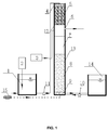
FIG. 1 is a structure diagram of a denitrification biofilter device in accordance with one embodiment of the invention; -
FIG. 2 is a structure diagram of a filler supporting plate in accordance with one embodiment of the invention; and -
FIG. 3 is a cross-sectional view taken from line A-A ofFIG. 2 . In the drawings, the following numbers are used: 1. Regulating pool; 2. First doser; 3. Second doser; 4. Uniform water distributor; 5. Filler layer; 6. Backwash water outlet; 7. Buffer layer; 8. Filter layer; 9. Supporting layer; 10. Backwash pump; 11. Water inlet pump; 12. Filler supporting plate; 13. Reactor body; 14. Water tank; and 15. Blower. - For further illustrating the invention, experiments detailing a denitrification biofilter device and a method for treating wastewater are described below. It should be noted that the following examples are intended to describe and not to limit the invention.
- As shown in
FIG. 1 , a denitrification biofilter device comprises: a regulatingpool 1, areactor body 13, and awater tank 14, a first doser 2, asecond doser 3, abackwash pump 10, a water inlet pump 11, and ablower 15. The first doser 2 is provided with a dosing tube and the dosing tube is extended into the regulatingpool 1. The regulatingpool 1 comprises a raw water inlet and a water outlet. The water outlet of the regulatingpool 1 is connected with the water inlet pump 11 and a top of thereactor body 13 in sequence via pipes. Thereactor body 13 is in a cylinder structure. A uniform water distributor 4, a filler layer 5, abuffer layer 7, a filter layer 8, and a supporting layer 9 are disposed from top to bottom inside thereactor body 13. Afiller supporting plate 12 is disposed between the filler layer 5 and thebuffer layer 7. A backwash water outlet 6 is disposed on a sidewall of thebuffer layer 7. A treated water outlet and a backwash water inlet are disposed at a bottom of thereactor body 13, and the treated water outlet and the backwash water inlet are connected to thewater tank 14 via pipes. Thebackwash pump 10 is disposed on a pipe between the backwash water inlet and thewater tank 14. Thesecond doser 3 is connected to the sidewall of thebuffer layer 7 via a pipe. The filler layer 5 is filled with zeolites, and each zeolite having a grain size of between 4 and 8 mm, a density of between 1.9 and 2.6 g/cm3, a porosity of more than or equal to 48%, and a specific surface area of between 570 and 670 m2/g. The uniform water distributor 4 comprises: a main pipe, branch pipes, and water distributing holes. 15 water distributing holes having equal diameters are evenly distributed at equal intervals on a lower side of each branch pipe. The supporting layer 9 is filled with pebbles, and each pebble has a grain size of between 2 and 6 mm and a density of 2.65 g/cm3. The filter layer 8 is filled with sea sand having a grain size of between 2 and 3 mm. A center of thefiller supporting plate 12 is designed in the absence of holes. Four curved holes are disposed on a periphery of thefiller supporting plate 12 contacting with the inner wall of thereactor body 13. Each of the curved holes has a radian of 1.05 rad and a width of 4 mm. A distance between a center position of each curved hole and an inner wall of thereactor body 13 is 0.5 mm, and the four curved holes are uniformly distributed in relative to the center of thefiller supporting plate 12. Such shape design enables the downwardly flowing wastewater to pass through the curved holes in the form of a laminar flow along the inner wall of thereactor body 13 to enter the buffer layer, thereby avoiding water whirlpool that occurs in the conventional water flowing holes and preventing the oxygen in the air from entering the water. The denitrification biofilter is constantly fed with water by the water inlet pump. The constant water level operation is capable of decreasing the cascade and avoiding the production of the dissolved oxygen. - A method for treating wastewater is conducted as follows:
- 1) Wastewater to be treated is introduced into the regulating
pool 1. The first doser 2 is opened, and an ammonium chloride solution is added to the regulatingpool 1 via the first doser 2 to enable a concentration of ammonia nitrogen to be 1.6 ± 0.3 mg/L. A removal rate of ammonia nitrogen after 22 days treatment exceeds 76% and a concentration of ammonia nitrogen is stable. After that, the first doser 2 is closed. When the concentration of ammonia nitrogen of the influent is 0.78 mg/L, the filler layer 5 is capable of decreasing the dissolved oxygen of the influent from 6.70 mg/L to 4.15 mg/L. - 2) The water inlet pump 11 is started, the water passes through the uniform water distributor 4 to enter the filler layer 5 where NH4 +-N of the influent is absorbed by the zeolites, nitrification of the nitrification bacteria occurs using NH4 +-N and the dissolved water, and NH4 +-N is converted into nitrate nitrogen and nitrite nitrogen.
- 3) The water flowing out of the filler layer 5 passes through curved holes of the
filler supporting plate 12 along the sidewall of the reactor body to enter thebuffer layer 7 and then to flow directly into the filter layer 8. Meanwhile, thesecond doser 3 is operated to add sodium acetate to thebuffer layer 7 as an external carbon source. The external carbon source and the original BOD in the wastewater serve as the organic carbon source for the denitrification bacteria in the filter layer 8 to reduce the nitrite radicals and the nitrate radicals into nitrogen. After 12 days treatment, the removal rate of the nitrate nitrogen in the filter layer 8 reaches 84% and is stabilized. - 4) The water after being treated by the filter layer 8 passes through the supporting layer 9 and enters the
water tank 14. - 5) One part of the water in the
water tank 14 is used to backwash the filter layer 8 when thebackwash pump 10 is opened, the water/gas simultaneously backwash the filter layer 8 for 3 min with a water intensity of 8 L/(s·m2) and a gas intensity of 14 L/(s·m2). The remaining water reaching the standard is discharged. - The filler layer is able to effectively decrease the inhibition effect of the dissolved oxygen on the denitrification, so that the external carbon-nitrogen ratio is decreased from C/N = 3 to C/N = 1.86 on the premise of a constant total nitrogen concentration.
- The device having a hydraulic loading of 2 m3/(m2h) and an external carbon-nitrogen ratio of C/N = 1.86 is utilized, and changes in water quality before and after treatment are as follows:
NH3-N (mg/L) NO3-N (mg/L) NO2-N (mg/L) TN (mg/L) SS (mg/L) TP (mg/L) COD (mg/L) Before treatment 0.78 8.50 0.0083 9.67 7.8 0.23 33.56 After treatment 0.20 1.06 0.023 1.39 1.5 0.07 28.16 - When the hydraulic loading is increased to 4 m3/(m2h), the total nitrogen of the effluent is 2.62 mg/L, which still satisfies the total nitrogen of the effluent < 3 mg/L.
- Because of the strong absorption effect of the zeolite on NH4 +-N, the total nitrogen of the effluent of the denitrification biofilter is still stabilized within 3 mg/L even when the secondary effluent from the sewage is unstable and ammonia nitrogen loading is increased to 5 mg/L.
Claims (7)
- A denitrification biofilter device, comprising:a) a regulating pool (1), the regulating pool (1) comprising a raw water inlet and a water outlet;b) a reactor body (13), the reactor body (13) comprising a uniform water distributor (4), a filler layer (5), a buffer layer (7), a filter layer (8), a supporting layer (9), a filler supporting plate (12), a backwash water outlet (6), a treated water outlet, and a backwash water inlet;c) a water tank (14);d) a first doser (2), the first doser (2) comprising a dosing tube;e) a second doser (3);f) a backwash pump (10);g) a water inlet pump (11); andh) a blower (15);wherein
the dosing tube is extended into the regulating pool (1);
the water outlet of the regulating pool (1) is connected to the water inlet pump (11) and a top of the reactor body (13) via pipes;
the reactor body (13) is in a cylinder structure;
the uniform water distributor (4), the filler layer (5), the buffer layer (7), the filter layer (8), and the supporting layer (9) are disposed inside the reactor body (13) from top to bottom;
the filler supporting plate (12) is disposed between the filler layer (5) and the buffer layer (7);
a plurality of curved holes is disposed at a periphery of the filler supporting plate (12);
the backwash water outlet (6) is disposed on a sidewall of the buffer layer (7);
the treated water outlet and the backwash water inlet are disposed at a bottom of the reactor body (13) and are connected to the water tank (14) via pipes, respectively;
the backwash pump (10) is disposed on a pipe between the backwash water inlet and the water tank (14);
the second doser (3) is connected to the sidewall of the buffer layer (7) via a pipe;
the buffer layer (7) is empty; and
the filler layer (5) is filled with zeolites having a grain size of between 4 and 8 mm, a density of between 1.9 and 2.6 g/cm3, a porosity of more than or equal to 48%, and a specific surface area of between 570 and 670 m2/g. - The device of claim 1, characterized in thatthe uniform water distributor (4) comprises: a main pipe, branch pipes, and water distributing holes; andthe water distributing holes having equal diameters are evenly disposed at equal intervals at a lower side of each branch pipe.
- The device of claim 1, characterized in that the supporting layer (9) is filled with pebbles, each pebble has a grain size of between 2 and 6 mm and a density of 2.65 g/cm3.
- The device of claim 1, characterized in that the filter layer (8) is filled with sea sand having a grain size of between 2 and 3 mm.
- The device of claim 1, characterized in that four curved holes are disposed on the periphery of the filler supporting plate (12) contacting with an inner wall of the reactor body (13); and each of the curved holes has a radian of 1.05 rad and a width of 4 mm.
- A method for treating wastewater, the method taking place in the device according to any of claims 1-5 and the method comprising the following steps:1) introducing wastewater to be treated into the regulating pool (1), opening the first doser (2), and adding an ammonium chloride solution to the regulating pool (1) via the first doser (2) to allow a concentration of ammonia nitrogen to be 1.6 ± 0.3 mg/L;2) starting the water inlet pump (11) to enable water to pass through the uniform water distributor (4) to enter the filler layer (5) where NH4 +-N in the water is absorbed by zeolites and is converted into nitrate nitrogen and nitrite nitrogen by nitrifying bacteria via nitrification in the presence of dissolved oxygen in the water;3) allowing the water flowing out of the filler layer (5) to pass through holes arranged at the periphery of the filler supporting plate (12) along a sidewall of the reactor body (13) to enter the buffer layer (7) and then to flow directly into the filter layer (8), while starting the second doser (3), and adding sodium acetate to the buffer layer (7) as an external carbon source;4) introducing the water after being treated by the filter layer (8) to pass through the supporting layer (9) and to enter the water tank (14); and5) allowing one part of the water in the water tank (14) to backwash the filter layer (8) when the backwash pump (10) is started, and discharging the remaining water reaching a standard.
- The method of claim 6, characterized in that a dose of sodium acetate in step 3) satisfies a carbon content in sodium acetate/ a nitrogen content in an influent is equal to 1.86.
Applications Claiming Priority (1)
| Application Number | Priority Date | Filing Date | Title |
|---|---|---|---|
| CN201310497488.9A CN103496786B (en) | 2013-10-22 | 2013-10-22 | Low-energy-consumption denitrification biological filter and treatment method thereof |
Publications (2)
| Publication Number | Publication Date |
|---|---|
| EP2865653A1 EP2865653A1 (en) | 2015-04-29 |
| EP2865653B1 true EP2865653B1 (en) | 2016-07-13 |
Family
ID=49862079
Family Applications (1)
| Application Number | Title | Priority Date | Filing Date |
|---|---|---|---|
| EP14188570.7A Active EP2865653B1 (en) | 2013-10-22 | 2014-10-11 | Layered trickle filter and method for treating wastewater involving dosing of chemicals |
Country Status (3)
| Country | Link |
|---|---|
| US (1) | US10556814B2 (en) |
| EP (1) | EP2865653B1 (en) |
| CN (1) | CN103496786B (en) |
Families Citing this family (20)
| Publication number | Priority date | Publication date | Assignee | Title |
|---|---|---|---|---|
| CN103864269B (en) * | 2014-03-31 | 2015-12-09 | 温州大学 | A device for treating high-concentration ammonia-nitrogen wastewater and a process for using the device to treat high-concentration ammonia-nitrogen wastewater |
| CN104528932B (en) * | 2014-12-26 | 2016-08-17 | 上海中信水务产业有限公司 | A kind of advanced treatment of wastewater denitrification bio-filter apparatus system and process technique |
| CN104495879B (en) * | 2015-01-12 | 2016-05-11 | 武汉大学 | A kind of integrated form catalytic oxidation/dephosphorization denitrogenation-isolated by filtration bioreactor |
| CN106554132B (en) * | 2016-10-12 | 2017-12-22 | 南京大学 | A kind of the sewage deep nitrogen rejection facility and its operation method of high pollutant carrying capacity low energy consumption |
| CN106554077B (en) * | 2016-10-12 | 2017-11-07 | 南京大学 | It is a kind of to alleviate device and its operation method that denitrification deep-bed filter top layer is blocked |
| DE112019001717T5 (en) * | 2018-03-30 | 2020-12-24 | Ngk Insulators, Ltd. | Zeolite membrane complex, process for making zeolite membrane complex and separation process |
| CN108793405A (en) * | 2018-04-12 | 2018-11-13 | 北京林业大学 | Build sewage water denitrification dephosphorization apparatus method, denitrification dephosphorization apparatus and denitrification and dephosphorization method |
| CN109231726B (en) * | 2018-11-21 | 2024-03-05 | 南京柯若环境技术有限公司 | Composite humic filler biological filter system, combined process wastewater treatment system and wastewater treatment method |
| CN110655185A (en) * | 2018-12-07 | 2020-01-07 | 江苏省环境科学研究院 | A new method of denitrification in denitrification filter |
| CN109574205A (en) * | 2019-01-18 | 2019-04-05 | 厦门陆海科技工程有限公司 | A kind of biofilter and sewage water treatment method |
| CN110950433A (en) * | 2019-11-18 | 2020-04-03 | 深圳市慧创源环保科技有限公司 | Sewage treatment device |
| CN111233285A (en) * | 2020-03-25 | 2020-06-05 | 安徽中源锦天环境科技股份有限公司 | Integrated sewage purification and upgrading process |
| CN111704239A (en) * | 2020-06-19 | 2020-09-25 | 中清信益环境(南京)有限公司 | A kind of high-efficiency denitrification filter system and working method |
| CN113371823B (en) * | 2021-07-29 | 2022-12-23 | 中原环保股份有限公司 | Continuous operation device for limited denitrification of municipal sewage and denitrification method thereof |
| CN113582336A (en) * | 2021-08-25 | 2021-11-02 | 中交上海航道勘察设计研究院有限公司 | Modular water treatment device based on solid-phase denitrification material |
| CN114477622A (en) * | 2021-12-24 | 2022-05-13 | 北京建筑大学 | Rural sewage in-situ treatment and recycling system and method |
| CN114873703B (en) * | 2022-06-18 | 2023-05-12 | 四川达沃斯生态环保科技股份有限公司 | Sewage coagulation stirring device, sewage denitrification and dephosphorization system and treatment process thereof |
| CN116081900A (en) * | 2023-03-21 | 2023-05-09 | 山东鼎信生态环境有限公司 | Centralized treatment process and device for feces and wastewater of livestock and poultry raising |
| CN117164110B (en) * | 2023-11-03 | 2024-02-02 | 中国水产科学研究院黄海水产研究所 | A kind of solid phase nitrification baffle reactor |
| CN119371007A (en) * | 2024-12-12 | 2025-01-28 | 陕西迪奥环保集团有限公司 | A high-salt, high-COD, high-ammonia nitrogen denitrification treatment device |
Family Cites Families (16)
| Publication number | Priority date | Publication date | Assignee | Title |
|---|---|---|---|---|
| US3171802A (en) * | 1962-11-14 | 1965-03-02 | Gen Services Company | Sewage treatment |
| DE2553050A1 (en) * | 1975-11-26 | 1977-06-16 | Baensch Tetra Werke | EQUIPMENT AND METHOD FOR EXTRACTION OF POLLUTIONS SOLVED IN THE WATER, MAINLY NITRATES |
| US4351729A (en) * | 1980-02-06 | 1982-09-28 | Celanese Corporation | Biological filter and process |
| US5374357A (en) * | 1993-03-19 | 1994-12-20 | D. W. Walker & Associates | Filter media treatment of a fluid flow to remove colloidal matter |
| DE19806938A1 (en) * | 1998-02-19 | 1999-08-26 | Philipp Mueller Gmbh | Stationary bed reactor for denitrification of water, used in sewage works with biological unit |
| US6998048B1 (en) * | 2002-12-09 | 2006-02-14 | Keith Dobie | Method and apparatus for cleaning effluent |
| CN2835234Y (en) * | 2005-09-09 | 2006-11-08 | 山东大学 | Integrated denitrogenation and dephosphorization biofilter |
| CN101264976A (en) * | 2008-04-28 | 2008-09-17 | 同济大学 | Supplementary carbon source anoxic biofilter deep nitrogen and phosphorus removal treatment system |
| US7914678B2 (en) * | 2008-05-30 | 2011-03-29 | Beggs Robert A | Backwashing unsaturated wastewater filter |
| CN201512459U (en) * | 2009-10-10 | 2010-06-23 | 重庆泰兴环保工程有限公司 | High-efficiency anaerobic drop water fast filtration urban sewage treatment device |
| US8388833B2 (en) * | 2010-09-23 | 2013-03-05 | Biofilter Systems, Llc | System and process for removing nitrogen compounds and odors from wastewater and wastewater treatment system |
| CN101880086A (en) * | 2010-01-18 | 2010-11-10 | 王鹤立 | Complex biological filter for synchronously treating sewage and off odor |
| US20120024798A1 (en) * | 2010-07-27 | 2012-02-02 | Timothy Michael Pickett | Selenium Removal Using Chemical Oxidation and Biological Reduction |
| US8440586B2 (en) * | 2010-02-26 | 2013-05-14 | Corning Incorporated | Low pressure drop extruded catalyst filter |
| CN103058372B (en) * | 2013-01-02 | 2014-02-26 | 北京工业大学 | Down-flow integrated nitrification and denitrification aeration biological filtering device and method |
| CN203498162U (en) * | 2013-10-22 | 2014-03-26 | 南京大学 | Denitrification biofilter device with low energy consumption |
-
2013
- 2013-10-22 CN CN201310497488.9A patent/CN103496786B/en active Active
-
2014
- 2014-08-27 US US14/470,931 patent/US10556814B2/en active Active
- 2014-10-11 EP EP14188570.7A patent/EP2865653B1/en active Active
Also Published As
| Publication number | Publication date |
|---|---|
| US10556814B2 (en) | 2020-02-11 |
| EP2865653A1 (en) | 2015-04-29 |
| US20150108066A1 (en) | 2015-04-23 |
| CN103496786B (en) | 2015-06-17 |
| CN103496786A (en) | 2014-01-08 |
Similar Documents
| Publication | Publication Date | Title |
|---|---|---|
| EP2865653A1 (en) | Layered trickle filter and method for treating wastewater involving dosing of chemicals | |
| KR101473050B1 (en) | Method and device for removing biological nitrogen and support therefor | |
| KR100822667B1 (en) | Wastewater Advanced Treatment System | |
| CN105330099B (en) | An integrated wastewater treatment device and petrochemical secondary effluent treatment method | |
| JP6939724B2 (en) | Sewage treatment method and equipment | |
| CN109970196A (en) | A kind of integrated form integrated waste water treating tank of application biology multiplication and fluidized-bed process | |
| CN104071949A (en) | Integrated hybrid biomembrane-activated sludge reaction system and application method thereof | |
| KR101198334B1 (en) | Apparatus and Method for Treating Wastewater Using Zeolites Having Media | |
| CN103214090B (en) | Anoxic humic filler filter tank and method for treating nitrogen containing degradation-resistant wastewater | |
| KR101779492B1 (en) | Waste water treatment system | |
| CN107381958A (en) | Carbon nitrogen divergence type denitrification process | |
| CN213680295U (en) | High-concentration ammonia nitrogen wastewater treatment device | |
| CN204958648U (en) | Ozone and biological nest processing technique combination treatment refractory wastewater equipment | |
| CN104556372B (en) | Method for adsorption separation of organic matters by residual sludge | |
| CN205603328U (en) | Low denitrification filtering pond system of oxygenating | |
| CN106186321A (en) | A kind of integrated energy-saving nitrogen rejection facility and method | |
| CN203498162U (en) | Denitrification biofilter device with low energy consumption | |
| CN207108603U (en) | A2O2Sewage disposal system | |
| CN214167719U (en) | Rare earth tail water denitrification treatment device | |
| CN206033496U (en) | Sewage treatment system based on two -stage bological aerated filter | |
| CN105984991A (en) | Process for advanced treatment of sewage | |
| CN214990949U (en) | Difficult degradation industrial waste water treatment system | |
| TW202202454A (en) | Aerobic biological processing method and device | |
| KR100510406B1 (en) | The apparatus and the method of wastewater purification by anoxic-aerobic fluidizied bed | |
| KR100862184B1 (en) | Anaerobic or anoxic reactor employing density-controlled medias, apparatus and method for treating wastewater using the same |
Legal Events
| Date | Code | Title | Description |
|---|---|---|---|
| PUAI | Public reference made under article 153(3) epc to a published international application that has entered the european phase |
Free format text: ORIGINAL CODE: 0009012 |
|
| 17P | Request for examination filed |
Effective date: 20141011 |
|
| AK | Designated contracting states |
Kind code of ref document: A1 Designated state(s): AL AT BE BG CH CY CZ DE DK EE ES FI FR GB GR HR HU IE IS IT LI LT LU LV MC MK MT NL NO PL PT RO RS SE SI SK SM TR |
|
| AX | Request for extension of the european patent |
Extension state: BA ME |
|
| R17P | Request for examination filed (corrected) |
Effective date: 20151027 |
|
| RBV | Designated contracting states (corrected) |
Designated state(s): AL AT BE BG CH CY CZ DE DK EE ES FI FR GB GR HR HU IE IS IT LI LT LU LV MC MK MT NL NO PL PT RO RS SE SI SK SM TR |
|
| GRAP | Despatch of communication of intention to grant a patent |
Free format text: ORIGINAL CODE: EPIDOSNIGR1 |
|
| INTG | Intention to grant announced |
Effective date: 20160209 |
|
| GRAS | Grant fee paid |
Free format text: ORIGINAL CODE: EPIDOSNIGR3 |
|
| GRAA | (expected) grant |
Free format text: ORIGINAL CODE: 0009210 |
|
| AK | Designated contracting states |
Kind code of ref document: B1 Designated state(s): AL AT BE BG CH CY CZ DE DK EE ES FI FR GB GR HR HU IE IS IT LI LT LU LV MC MK MT NL NO PL PT RO RS SE SI SK SM TR |
|
| REG | Reference to a national code |
Ref country code: GB Ref legal event code: FG4D |
|
| REG | Reference to a national code |
Ref country code: AT Ref legal event code: REF Ref document number: 812149 Country of ref document: AT Kind code of ref document: T Effective date: 20160715 Ref country code: CH Ref legal event code: EP |
|
| REG | Reference to a national code |
Ref country code: IE Ref legal event code: FG4D |
|
| REG | Reference to a national code |
Ref country code: DE Ref legal event code: R096 Ref document number: 602014002658 Country of ref document: DE |
|
| REG | Reference to a national code |
Ref country code: FR Ref legal event code: PLFP Year of fee payment: 3 |
|
| REG | Reference to a national code |
Ref country code: LT Ref legal event code: MG4D |
|
| REG | Reference to a national code |
Ref country code: NL Ref legal event code: MP Effective date: 20160713 |
|
| REG | Reference to a national code |
Ref country code: AT Ref legal event code: MK05 Ref document number: 812149 Country of ref document: AT Kind code of ref document: T Effective date: 20160713 |
|
| PG25 | Lapsed in a contracting state [announced via postgrant information from national office to epo] |
Ref country code: NL Free format text: LAPSE BECAUSE OF FAILURE TO SUBMIT A TRANSLATION OF THE DESCRIPTION OR TO PAY THE FEE WITHIN THE PRESCRIBED TIME-LIMIT Effective date: 20160713 Ref country code: HR Free format text: LAPSE BECAUSE OF FAILURE TO SUBMIT A TRANSLATION OF THE DESCRIPTION OR TO PAY THE FEE WITHIN THE PRESCRIBED TIME-LIMIT Effective date: 20160713 Ref country code: IS Free format text: LAPSE BECAUSE OF FAILURE TO SUBMIT A TRANSLATION OF THE DESCRIPTION OR TO PAY THE FEE WITHIN THE PRESCRIBED TIME-LIMIT Effective date: 20161113 Ref country code: IT Free format text: LAPSE BECAUSE OF FAILURE TO SUBMIT A TRANSLATION OF THE DESCRIPTION OR TO PAY THE FEE WITHIN THE PRESCRIBED TIME-LIMIT Effective date: 20160713 Ref country code: RS Free format text: LAPSE BECAUSE OF FAILURE TO SUBMIT A TRANSLATION OF THE DESCRIPTION OR TO PAY THE FEE WITHIN THE PRESCRIBED TIME-LIMIT Effective date: 20160713 Ref country code: NO Free format text: LAPSE BECAUSE OF FAILURE TO SUBMIT A TRANSLATION OF THE DESCRIPTION OR TO PAY THE FEE WITHIN THE PRESCRIBED TIME-LIMIT Effective date: 20161013 Ref country code: FI Free format text: LAPSE BECAUSE OF FAILURE TO SUBMIT A TRANSLATION OF THE DESCRIPTION OR TO PAY THE FEE WITHIN THE PRESCRIBED TIME-LIMIT Effective date: 20160713 Ref country code: LT Free format text: LAPSE BECAUSE OF FAILURE TO SUBMIT A TRANSLATION OF THE DESCRIPTION OR TO PAY THE FEE WITHIN THE PRESCRIBED TIME-LIMIT Effective date: 20160713 |
|
| PG25 | Lapsed in a contracting state [announced via postgrant information from national office to epo] |
Ref country code: ES Free format text: LAPSE BECAUSE OF FAILURE TO SUBMIT A TRANSLATION OF THE DESCRIPTION OR TO PAY THE FEE WITHIN THE PRESCRIBED TIME-LIMIT Effective date: 20160713 Ref country code: PL Free format text: LAPSE BECAUSE OF FAILURE TO SUBMIT A TRANSLATION OF THE DESCRIPTION OR TO PAY THE FEE WITHIN THE PRESCRIBED TIME-LIMIT Effective date: 20160713 Ref country code: AT Free format text: LAPSE BECAUSE OF FAILURE TO SUBMIT A TRANSLATION OF THE DESCRIPTION OR TO PAY THE FEE WITHIN THE PRESCRIBED TIME-LIMIT Effective date: 20160713 Ref country code: SE Free format text: LAPSE BECAUSE OF FAILURE TO SUBMIT A TRANSLATION OF THE DESCRIPTION OR TO PAY THE FEE WITHIN THE PRESCRIBED TIME-LIMIT Effective date: 20160713 Ref country code: BE Free format text: LAPSE BECAUSE OF NON-PAYMENT OF DUE FEES Effective date: 20160713 Ref country code: GR Free format text: LAPSE BECAUSE OF FAILURE TO SUBMIT A TRANSLATION OF THE DESCRIPTION OR TO PAY THE FEE WITHIN THE PRESCRIBED TIME-LIMIT Effective date: 20161014 Ref country code: PT Free format text: LAPSE BECAUSE OF FAILURE TO SUBMIT A TRANSLATION OF THE DESCRIPTION OR TO PAY THE FEE WITHIN THE PRESCRIBED TIME-LIMIT Effective date: 20161114 Ref country code: LV Free format text: LAPSE BECAUSE OF FAILURE TO SUBMIT A TRANSLATION OF THE DESCRIPTION OR TO PAY THE FEE WITHIN THE PRESCRIBED TIME-LIMIT Effective date: 20160713 |
|
| REG | Reference to a national code |
Ref country code: DE Ref legal event code: R097 Ref document number: 602014002658 Country of ref document: DE |
|
| PG25 | Lapsed in a contracting state [announced via postgrant information from national office to epo] |
Ref country code: EE Free format text: LAPSE BECAUSE OF FAILURE TO SUBMIT A TRANSLATION OF THE DESCRIPTION OR TO PAY THE FEE WITHIN THE PRESCRIBED TIME-LIMIT Effective date: 20160713 Ref country code: RO Free format text: LAPSE BECAUSE OF FAILURE TO SUBMIT A TRANSLATION OF THE DESCRIPTION OR TO PAY THE FEE WITHIN THE PRESCRIBED TIME-LIMIT Effective date: 20160713 |
|
| PLBE | No opposition filed within time limit |
Free format text: ORIGINAL CODE: 0009261 |
|
| STAA | Information on the status of an ep patent application or granted ep patent |
Free format text: STATUS: NO OPPOSITION FILED WITHIN TIME LIMIT |
|
| PG25 | Lapsed in a contracting state [announced via postgrant information from national office to epo] |
Ref country code: CZ Free format text: LAPSE BECAUSE OF FAILURE TO SUBMIT A TRANSLATION OF THE DESCRIPTION OR TO PAY THE FEE WITHIN THE PRESCRIBED TIME-LIMIT Effective date: 20160713 Ref country code: SM Free format text: LAPSE BECAUSE OF FAILURE TO SUBMIT A TRANSLATION OF THE DESCRIPTION OR TO PAY THE FEE WITHIN THE PRESCRIBED TIME-LIMIT Effective date: 20160713 Ref country code: DK Free format text: LAPSE BECAUSE OF FAILURE TO SUBMIT A TRANSLATION OF THE DESCRIPTION OR TO PAY THE FEE WITHIN THE PRESCRIBED TIME-LIMIT Effective date: 20160713 Ref country code: SK Free format text: LAPSE BECAUSE OF FAILURE TO SUBMIT A TRANSLATION OF THE DESCRIPTION OR TO PAY THE FEE WITHIN THE PRESCRIBED TIME-LIMIT Effective date: 20160713 Ref country code: BG Free format text: LAPSE BECAUSE OF FAILURE TO SUBMIT A TRANSLATION OF THE DESCRIPTION OR TO PAY THE FEE WITHIN THE PRESCRIBED TIME-LIMIT Effective date: 20161013 |
|
| 26N | No opposition filed |
Effective date: 20170418 |
|
| REG | Reference to a national code |
Ref country code: IE Ref legal event code: MM4A |
|
| PG25 | Lapsed in a contracting state [announced via postgrant information from national office to epo] |
Ref country code: SI Free format text: LAPSE BECAUSE OF FAILURE TO SUBMIT A TRANSLATION OF THE DESCRIPTION OR TO PAY THE FEE WITHIN THE PRESCRIBED TIME-LIMIT Effective date: 20160713 Ref country code: LU Free format text: LAPSE BECAUSE OF NON-PAYMENT OF DUE FEES Effective date: 20161011 |
|
| REG | Reference to a national code |
Ref country code: FR Ref legal event code: PLFP Year of fee payment: 4 |
|
| PG25 | Lapsed in a contracting state [announced via postgrant information from national office to epo] |
Ref country code: IE Free format text: LAPSE BECAUSE OF NON-PAYMENT OF DUE FEES Effective date: 20161011 |
|
| PG25 | Lapsed in a contracting state [announced via postgrant information from national office to epo] |
Ref country code: HU Free format text: LAPSE BECAUSE OF FAILURE TO SUBMIT A TRANSLATION OF THE DESCRIPTION OR TO PAY THE FEE WITHIN THE PRESCRIBED TIME-LIMIT; INVALID AB INITIO Effective date: 20141011 |
|
| REG | Reference to a national code |
Ref country code: CH Ref legal event code: PL |
|
| PG25 | Lapsed in a contracting state [announced via postgrant information from national office to epo] |
Ref country code: MC Free format text: LAPSE BECAUSE OF FAILURE TO SUBMIT A TRANSLATION OF THE DESCRIPTION OR TO PAY THE FEE WITHIN THE PRESCRIBED TIME-LIMIT Effective date: 20160713 Ref country code: CY Free format text: LAPSE BECAUSE OF FAILURE TO SUBMIT A TRANSLATION OF THE DESCRIPTION OR TO PAY THE FEE WITHIN THE PRESCRIBED TIME-LIMIT Effective date: 20160713 Ref country code: MK Free format text: LAPSE BECAUSE OF FAILURE TO SUBMIT A TRANSLATION OF THE DESCRIPTION OR TO PAY THE FEE WITHIN THE PRESCRIBED TIME-LIMIT Effective date: 20160713 Ref country code: MT Free format text: LAPSE BECAUSE OF NON-PAYMENT OF DUE FEES Effective date: 20161031 |
|
| PG25 | Lapsed in a contracting state [announced via postgrant information from national office to epo] |
Ref country code: LI Free format text: LAPSE BECAUSE OF NON-PAYMENT OF DUE FEES Effective date: 20171031 Ref country code: CH Free format text: LAPSE BECAUSE OF NON-PAYMENT OF DUE FEES Effective date: 20171031 |
|
| REG | Reference to a national code |
Ref country code: FR Ref legal event code: PLFP Year of fee payment: 5 |
|
| PG25 | Lapsed in a contracting state [announced via postgrant information from national office to epo] |
Ref country code: TR Free format text: LAPSE BECAUSE OF FAILURE TO SUBMIT A TRANSLATION OF THE DESCRIPTION OR TO PAY THE FEE WITHIN THE PRESCRIBED TIME-LIMIT Effective date: 20160713 Ref country code: AL Free format text: LAPSE BECAUSE OF FAILURE TO SUBMIT A TRANSLATION OF THE DESCRIPTION OR TO PAY THE FEE WITHIN THE PRESCRIBED TIME-LIMIT Effective date: 20160713 |
|
| PGFP | Annual fee paid to national office [announced via postgrant information from national office to epo] |
Ref country code: GB Payment date: 20250929 Year of fee payment: 12 |
|
| PGFP | Annual fee paid to national office [announced via postgrant information from national office to epo] |
Ref country code: DE Payment date: 20251224 Year of fee payment: 12 |
|
| PGFP | Annual fee paid to national office [announced via postgrant information from national office to epo] |
Ref country code: FR Payment date: 20251030 Year of fee payment: 12 |