EP2865607A1 - Ic tagged compound container lid - Google Patents
Ic tagged compound container lid Download PDFInfo
- Publication number
- EP2865607A1 EP2865607A1 EP20130810735 EP13810735A EP2865607A1 EP 2865607 A1 EP2865607 A1 EP 2865607A1 EP 20130810735 EP20130810735 EP 20130810735 EP 13810735 A EP13810735 A EP 13810735A EP 2865607 A1 EP2865607 A1 EP 2865607A1
- Authority
- EP
- European Patent Office
- Prior art keywords
- cap
- over
- inner cap
- tag
- container lid
- Prior art date
- Legal status (The legal status is an assumption and is not a legal conclusion. Google has not performed a legal analysis and makes no representation as to the accuracy of the status listed.)
- Granted
Links
Images








Classifications
-
- G—PHYSICS
- G06—COMPUTING OR CALCULATING; COUNTING
- G06K—GRAPHICAL DATA READING; PRESENTATION OF DATA; RECORD CARRIERS; HANDLING RECORD CARRIERS
- G06K19/00—Record carriers for use with machines and with at least a part designed to carry digital markings
- G06K19/06—Record carriers for use with machines and with at least a part designed to carry digital markings characterised by the kind of the digital marking, e.g. shape, nature, code
- G06K19/067—Record carriers with conductive marks, printed circuits or semiconductor circuit elements, e.g. credit or identity cards also with resonating or responding marks without active components
- G06K19/07—Record carriers with conductive marks, printed circuits or semiconductor circuit elements, e.g. credit or identity cards also with resonating or responding marks without active components with integrated circuit chips
- G06K19/077—Constructional details, e.g. mounting of circuits in the carrier
- G06K19/07749—Constructional details, e.g. mounting of circuits in the carrier the record carrier being capable of non-contact communication, e.g. constructional details of the antenna of a non-contact smart card
- G06K19/07798—Constructional details, e.g. mounting of circuits in the carrier the record carrier being capable of non-contact communication, e.g. constructional details of the antenna of a non-contact smart card part of the antenna or the integrated circuit being adapted for rupturing or breaking, e.g. record carriers functioning as sealing devices for detecting not-authenticated opening of containers
-
- B—PERFORMING OPERATIONS; TRANSPORTING
- B65—CONVEYING; PACKING; STORING; HANDLING THIN OR FILAMENTARY MATERIAL
- B65D—CONTAINERS FOR STORAGE OR TRANSPORT OF ARTICLES OR MATERIALS, e.g. BAGS, BARRELS, BOTTLES, BOXES, CANS, CARTONS, CRATES, DRUMS, JARS, TANKS, HOPPERS, FORWARDING CONTAINERS; ACCESSORIES, CLOSURES, OR FITTINGS THEREFOR; PACKAGING ELEMENTS; PACKAGES
- B65D41/00—Caps, e.g. crown caps or crown seals, i.e. members having parts arranged for engagement with the external periphery of a neck or wall defining a pouring opening or discharge aperture; Protective cap-like covers for closure members, e.g. decorative covers of metal foil or paper
- B65D41/32—Caps or cap-like covers with lines of weakness, tearing-strips, tags, or like opening or removal devices, e.g. to facilitate formation of pouring openings
- B65D41/34—Threaded or like caps or cap-like covers provided with tamper elements formed in, or attached to, the closure skirt
- B65D41/3423—Threaded or like caps or cap-like covers provided with tamper elements formed in, or attached to, the closure skirt with flexible tabs, or elements rotated from a non-engaging to an engaging position, formed on the tamper element or in the closure skirt
-
- B—PERFORMING OPERATIONS; TRANSPORTING
- B65—CONVEYING; PACKING; STORING; HANDLING THIN OR FILAMENTARY MATERIAL
- B65D—CONTAINERS FOR STORAGE OR TRANSPORT OF ARTICLES OR MATERIALS, e.g. BAGS, BARRELS, BOTTLES, BOXES, CANS, CARTONS, CRATES, DRUMS, JARS, TANKS, HOPPERS, FORWARDING CONTAINERS; ACCESSORIES, CLOSURES, OR FITTINGS THEREFOR; PACKAGING ELEMENTS; PACKAGES
- B65D41/00—Caps, e.g. crown caps or crown seals, i.e. members having parts arranged for engagement with the external periphery of a neck or wall defining a pouring opening or discharge aperture; Protective cap-like covers for closure members, e.g. decorative covers of metal foil or paper
- B65D41/32—Caps or cap-like covers with lines of weakness, tearing-strips, tags, or like opening or removal devices, e.g. to facilitate formation of pouring openings
- B65D41/34—Threaded or like caps or cap-like covers provided with tamper elements formed in, or attached to, the closure skirt
- B65D41/3442—Threaded or like caps or cap-like covers provided with tamper elements formed in, or attached to, the closure skirt with rigid bead or projections formed on the tamper element and coacting with bead or projections on the container
- B65D41/3447—Threaded or like caps or cap-like covers provided with tamper elements formed in, or attached to, the closure skirt with rigid bead or projections formed on the tamper element and coacting with bead or projections on the container the tamper element being integrally connected to the closure by means of bridges
-
- B—PERFORMING OPERATIONS; TRANSPORTING
- B65—CONVEYING; PACKING; STORING; HANDLING THIN OR FILAMENTARY MATERIAL
- B65D—CONTAINERS FOR STORAGE OR TRANSPORT OF ARTICLES OR MATERIALS, e.g. BAGS, BARRELS, BOTTLES, BOXES, CANS, CARTONS, CRATES, DRUMS, JARS, TANKS, HOPPERS, FORWARDING CONTAINERS; ACCESSORIES, CLOSURES, OR FITTINGS THEREFOR; PACKAGING ELEMENTS; PACKAGES
- B65D51/00—Closures not otherwise provided for
- B65D51/18—Arrangements of closures with protective outer cap-like covers or of two or more co-operating closures
-
- B—PERFORMING OPERATIONS; TRANSPORTING
- B65—CONVEYING; PACKING; STORING; HANDLING THIN OR FILAMENTARY MATERIAL
- B65D—CONTAINERS FOR STORAGE OR TRANSPORT OF ARTICLES OR MATERIALS, e.g. BAGS, BARRELS, BOTTLES, BOXES, CANS, CARTONS, CRATES, DRUMS, JARS, TANKS, HOPPERS, FORWARDING CONTAINERS; ACCESSORIES, CLOSURES, OR FITTINGS THEREFOR; PACKAGING ELEMENTS; PACKAGES
- B65D55/00—Accessories for container closures not otherwise provided for
- B65D55/02—Locking devices; Means for discouraging or indicating unauthorised opening or removal of closure
-
- G—PHYSICS
- G08—SIGNALLING
- G08B—SIGNALLING SYSTEMS, e.g. PERSONAL CALLING SYSTEMS; ORDER TELEGRAPHS; ALARM SYSTEMS
- G08B13/00—Burglar, theft or intruder alarms
- G08B13/22—Electrical actuation
- G08B13/24—Electrical actuation by interference with electromagnetic field distribution
- G08B13/2402—Electronic Article Surveillance [EAS], i.e. systems using tags for detecting removal of a tagged item from a secure area, e.g. tags for detecting shoplifting
- G08B13/2428—Tag details
- G08B13/2434—Tag housing and attachment details
-
- B—PERFORMING OPERATIONS; TRANSPORTING
- B65—CONVEYING; PACKING; STORING; HANDLING THIN OR FILAMENTARY MATERIAL
- B65D—CONTAINERS FOR STORAGE OR TRANSPORT OF ARTICLES OR MATERIALS, e.g. BAGS, BARRELS, BOTTLES, BOXES, CANS, CARTONS, CRATES, DRUMS, JARS, TANKS, HOPPERS, FORWARDING CONTAINERS; ACCESSORIES, CLOSURES, OR FITTINGS THEREFOR; PACKAGING ELEMENTS; PACKAGES
- B65D2203/00—Decoration means, markings, information elements, contents indicators
- B65D2203/10—Transponders
-
- B—PERFORMING OPERATIONS; TRANSPORTING
- B65—CONVEYING; PACKING; STORING; HANDLING THIN OR FILAMENTARY MATERIAL
- B65D—CONTAINERS FOR STORAGE OR TRANSPORT OF ARTICLES OR MATERIALS, e.g. BAGS, BARRELS, BOTTLES, BOXES, CANS, CARTONS, CRATES, DRUMS, JARS, TANKS, HOPPERS, FORWARDING CONTAINERS; ACCESSORIES, CLOSURES, OR FITTINGS THEREFOR; PACKAGING ELEMENTS; PACKAGES
- B65D2251/00—Details relating to container closures
- B65D2251/0003—Two or more closures
- B65D2251/0006—Upper closure
- B65D2251/0015—Upper closure of the 41-type
-
- B—PERFORMING OPERATIONS; TRANSPORTING
- B65—CONVEYING; PACKING; STORING; HANDLING THIN OR FILAMENTARY MATERIAL
- B65D—CONTAINERS FOR STORAGE OR TRANSPORT OF ARTICLES OR MATERIALS, e.g. BAGS, BARRELS, BOTTLES, BOXES, CANS, CARTONS, CRATES, DRUMS, JARS, TANKS, HOPPERS, FORWARDING CONTAINERS; ACCESSORIES, CLOSURES, OR FITTINGS THEREFOR; PACKAGING ELEMENTS; PACKAGES
- B65D2251/00—Details relating to container closures
- B65D2251/0003—Two or more closures
- B65D2251/0068—Lower closure
- B65D2251/0078—Lower closure of the 41-type
Definitions
- This invention relates to a packing member used for sealing the container mouth portion. More specifically, the invention relates to a packing member provided with an IC tag that stores product information.
- Bar codes have heretofore been widely used for a variety of kinds of products to display product information such as date of production, names of the manufacturers and distributors, expiration dates, etc.
- the surface on where the bar codes are printed must be flat. Therefore, in the field of packing materials such as bottles and caps, limitation is imposed on the surface on where the bar codes are printed and also on the quantity of information that can be encoded.
- the IC tag is also called RFID (radio frequency identifier), and is a very small communication terminal in the form of a tag that includes an IC chip storing predetermined information buried together with an antenna in a dielectric material such as resin or glass.
- the IC tag is for reading out product information stored in the IC chip by way of radio communication.
- a memory in the IC chip is capable of storing the data of, for example, several hundreds of bytes offering such an advantage that a lot of product information can be stored therein.
- the IC tag is capable of reading out the recorded information in a non-contacting manner and is free of such a problem as wear caused by contact. Besides, it has such an advantage as being realized in a form that meets the form of the product and in small size and in reduced thickness.
- a patent document 1 discloses a cap having an IC tag buried in a top plate thereof when the cap is opened.
- a patent document 2 discloses a method of detecting the unsealing relying on the breakage of the lead wire that connects the IC chip to the antenna in the IC tag.
- a patent document 3 discloses an art of recognizing the fact of unsealing based on that an antenna provided in the cap body is broken accompanying the unsealing of the upper lid coupled to the cap body that is fitted onto the container mouth portion.
- the IC chip of the IC tag is provided in the container body or in a portion belonging to the container body (concretely, in a tamper evidence band that is cut off from the cap when it is opened), the antenna and the lead wire are provided in a cap that is fitted by screw onto the container body, and the lead wire is broken when the cap is unsealed.
- the antenna and the lead wire that connects the IC chip to the antenna are provided in the cap which is separate from the container.
- the cap is provided with the IC tag of which the antenna and the IC chip are connected together through the lead wire.
- the cap is then fitted onto the container mouth portion and, thereafter, the IC chip portion only is stuck onto the container.
- the cap must be fitted onto the container mouth portion in a state where the IC chip is hanging down requiring a very cumbersome operation (capping operation) accompanied by such a probability that the IC chip and the lead wire are liable to be broken during the capping operation.
- the IC chip is provided on the tamper evidence band (TE band) that will be separated away from the cap when it is opened, difficulty is involved in fitting the IC chip on the TE band. More than that, it is not allowed to sufficiently prove the fact of unsealing based on the breakage of the lead wire that connects the IC chip to the antenna. That is, in this case, the breakage of the IC tag stands for the separation of the TE band, and the TE band that is separated away proves the history of unsealing of the cap. It will, therefore, be understood that the history of unsealing of the cap is proved by the separation of the TE band despite the history of unsealing has not been proved by the breakage of the IC tag.
- TE band tamper evidence band
- the IC tag is provided on a lid member that is separate from a lid member that is sealing the container mouth portion, and the lid member sealing the container mouth portion is unsealed quite separately from the operation for breaking the IC tag of the lid member in which the IC tag has been provided. That is, to unseal the container mouth portion according to the patent document 3, the IC tag must be broken in advance separately from the unsealing operation and, besides, the lid member (outer lid) that has the IC tag must be removed requiring, therefore, clumsy operation for unsealing the container mouth portion and, therefore, further improvements have been desired.
- Patent Documents
- an object of the present invention to provide a composite container lid with IC tag, in which the IC tag is attached to a cap that is formed as a unitary structure so will not to be separated away, facilitating the capping operation for fitting the cap to which the IC tag has been attached, enabling the IC tag to be broken when a lid member sealing the container mouth portion is unsealed, and permitting the container mouth portion to be unsealed simply and easily in a series of operations, the composite container lid being capable of reliably indicating the fact that the container mouth portion has been unsealed when the IC tag is broken.
- Another object of the present invention is to provide a composite container lid with IC tag which enables the information stored in an IC chip of the IC tag to be read out even after the container has been unsealed.
- a composite container lid which comprises an inner cap fitted onto the container mouth portion by screw engagement, an over-cap fitted onto the inner cap, and an IC tag; wherein the over-cap has a top panel and a skirt descending from the circumferential edge of the top panel; the inner cap has a top plate and a cylindrical wall descending from the circumferential edge of the top plate and having a thread formed in the inner surface thereof to come into screw engagement with the outer surface of the container mouth portion; an engaging means is provided between the inner surface of the skirt of the over-cap and the outer surface of the cylindrical wall of the inner cap to transmit the turn of the over-cap fitted onto the inner cap to the inner cap; and the IC tag is attached to the inner cap or to the over-cap in a manner that a circuit inclusive of an information transmission/reception antenna connected to an IC chip in the IC tag is broken by a motion of the over-cap relative to the inner cap caused at the time of unsealing the inner cap fitted onto the container mouth portion.
- the IC tag is provided on either the inner cap or the over-cap, but is not provided spanning over the separate members.
- the IC tag is not, either, provided on a portion such as the TE band that will be separated away at the time of unsealing. Therefore, the IC tag can be easily attached without being broken at the time of fitting the inner cap onto the container mouth portion or fitting the over-cap onto the inner cap.
- the inner cap is unsealed being linked to the operation of unsealing the over-cap.
- the circuit connected to the IC chip in the IC tag is broken due to the motion of the over-cap relative to the inner cap caused by the above operation. Therefore, the inner cap will have been removed from the container mouth portion when the circuit in the IC tag is broken. That is, if the inner cap is applied to sealing the container mouth portion, then there is no need of separately conducting the operation for unsealing the container mouth portion, and the unsealing operation does not become cumbersome.
- the IC tag includes the IC chip and a circuit that has the antenna for transmitting and receiving information to and from the IC chip (i.e., the IC chip and the antenna are connected together through a lead wire). If the antenna circuit is broken as a result of unsealing the over-cap, therefore, information stored in the IC chip can no longer be read out by the external unit. That is, the fact of unsealing can be recognized as it becomes impossible to read out the information. According to the present invention, the IC tag is effectively prevented from being broken at the time of attaching the IC tag or at the time of capping the over-cap or the inner cap. Therefore, reading of information that is rendered impossible proves the fact that the cap was unsealed maintaining very high precision contributing to greatly improving the function for guaranteeing the quality of the contents and the function for preventing tampering.
- the IC tag has not been provided on the TE band that will be separated away at the time of unsealing. Therefore, the history of unsealing is proved based on the breakage of the IC tag independently from proving the history of unsealing based on the TE band. Aided by the TE band, therefore, it is allowed to more reliably prove the history of unsealing.
- the IC tag is provided with a circuit dedicated to indicating the unsealing of the container (circuit for detecting the unsealing) and that the circuit for detecting the unsealing is connected to the IC chip in parallel with the above antenna circuit.
- the circuit for detecting the unsealing is selectively broken, and a change in the voltage caused by a change in the electric resistance stemming from the breakage of the circuit is read by using an external reading device to know the fact of unsealing.
- the unsealing is displayed without breaking the IC chip, the antenna or the lead wire connecting the IC chip to the antenna. Even after unsealed, therefore, the information stored in the IC chip can be directly read out.
- a trouble of the IC chip can be clearly distinguished from the unsealing, further improving the proof of history of unsealing. Even after unsealed, further, information in the IC chip can be read out and can be utilized for various objects such as campaigns.
- the composite container lid of the present invention it is desired to employ such means that a gap is maintained between the upper surface of the top plate of the inner cap and the lower surface of the top panel of the over-cap fitted onto the inner cap, the IC tag is attached to either the lower surface of the top panel of the over-cap or to the upper surface of the top plate of the inner cap, and a cutter is formed on the inner cap or on the over-cap to break the circuit of the IC tag.
- the circuit of the IC tag is broken and the operation for unsealing the container is conducted after the stopper band is separated away.
- the container which is still in the unsealed state can also be confirmed by the presence of the stopper band, contributing to enhancing the function for preventing tampering and for further improving the function for guaranteeing the quality of the content in the container.
- the composite container lids provided with the above stopper band can be classified into those of the polyhedrally engaging type, those of the inversely threaded type, those of the ratchet type and those of the fitting type depending on the types of engaging means that transmits the turn of the over-cap to the inner cap.
- the composite container lid of the polyhdedrally engaging type is so embodied that:
- the container can be unsealed by turning the over-cap while readily breaking the circuit of the IC tag.
- the inner cap is removed from the container mouth portion in a state where the over-cap is being fitted onto the inner cap.
- the inner cap can be easily separated away from the over-cap; i. e., the inner cap only can be used to easily seal the container mouth portion again, which is an advantage.
- the composite container lid of the inversely threaded type is such that the stopper band is so provided as can be separated away from the over-cap as described above, and employs such means that:
- the circuit of the IC tag is broken and the container is unsealed by simply turning the over-cap readily after the stopper band is separated away, offering such an advantage that the operation is very easily in addition to attaining the advantage of the above embodiment (3).
- the composite container lid of the ratchet type is such that the stopper band is so provided as can be separated away from the over-cap, and is so embodied that:
- This embodiment is advantageous in regard to that the IC tag can be very easily attached to a position where the circuit can be broken (positioning can be easily attained). Therefore, this embodiment can be favorably applied to a case where the IC tag cannot be easily attached to the top plate of the inner cap or to the top panel of the over-cap, in especially the form of the IC tag is rectangular. With the composite container lid of this type, too, the circuit of the IC tag can be broken and the container can be unsealed by the operation of only turning the over-cap readily after the stopper band is separated away.
- the composite container lid of the fitting type is such that the stopper band is so provided as can be separated away from the over-cap, and employs such means that:
- This embodiment requires an operation for once pushing the over-cap in after the stopper band is separated away. Namely, the lid of this embodiment cannot be easily unsealed by infants offering the so-called child resistance, and, therefore, can be favorably applied to the containers for containing medicines.
- the unsealing detection circuit in the IC tag is broken not by pushing the protuberance in but by being cut by the cutting pawl, offering an advantage in that the IC tag can be very easily attached to a position where the circuit can be broken (positioning is easily attained).
- the IC tag generally designated at 10 is provided, on the surface of a film base member 1, with a circuit that includes an IC chip 3 and a metal antenna (for transmitting/receiving information) 5, the metal antenna 5 being electrically connected to the IC chip 3 through a lead wire 7.
- the IC tag 10 is, further, provided with an unsealing detector circuit 9 in parallel with the circuit that includes the metal antenna 5.
- the circuit 9, too, is connected to the IC chip 3 through the lead wire 7.
- the film base member 1 is, usually, made from a thermoplastic resin that can be heat-melt adhered.
- a thermoplastic resin that can be heat-melt adhered.
- the thermoplastic resin though not specifically limited, there is, usually, used the same resin as the resin base member that constitutes an over-cap and an inner cap (these caps will be described later) to which the IC tag 10 will be attached.
- the IC tag 10 is to be attached to the cap made from a polyolefin, then it is desired that the film 1 is made from the polyolefin.
- the IC tag 10 with the IC chip 3 and the metal antenna 5 being formed on a polyethylene terephthalate resin film.
- a polyolefin resin layer such as of polyethylene or polypropylene is laminated on the back surface of the polyethylene terephthalate resin film 1 by using a suitable adhesive such as acid-modified olefin resin from the standpoint of attaching the IC tag 10 to the cap.
- the film substrate 1 there can also be used a paper.
- the IC chip 3 is, for example, flip-chip-mounted so as to be electrically conductive to the antenna 3 , and stores the information related to a product to which the IC tag 10 is attached as the signals are sent thereto through the antenna 3. Further, the information stored in the IC tag 10 is read out through the antenna 3.
- the IC chip 3 is, usually, protected by being molded with an electrically insulating curable resin such as polyimide or bismaleimide resin.
- the IC chip 3 can be, further, molded by being stuck with a paper.
- the IC chip 3 is storing information related to the content in the packing container (e. g. , producer, manufacturer, date of production, date of shipment, etc.), information related to the container, as well as information such as a change in the voltage that indicates the unsealing.
- the information is input or output in the form of high frequency signals utilizing chiefly the UHF band near 900 MHz or a frequency band of 13.56 MHz.
- the IC tag 10 and the circuit including the antenna 3 are not limited to those of the form shown in Fig. 1 .
- they may be in a rectangular form, or the unsealing detector circuit 9 may be in a multiplicity of spiral form.
- the unsealing detector circuit 9 does not have to be provided, as a matter of course.
- the antenna 5 may often be in a multiplicity of forms.
- the IC tag 10 has no unsealing detector circuit 9, and the antenna 5 includes a multiplicity of line portions Y in which two arcuate lines 5a and 5a are extending maintaining a gap d.
- the antenna 5 has two arcuate lines 5a to form the multiplicity of line portions Y.
- the number thereof may be further increased.
- the thickness t of the arcuate lines 5a (width in the radial direction) needs not be specifically limited and is so set as to possess a resonating length that meets the frequency of the signals that are used.
- the arcuate lines 5a and 5a are forming part of a circle but may also be forming part of an ellipse or of any other shape. Further, the lines 5a may often be forming a complete circle.
- the unsealing detector circuit 9 may be so set as to, when it is broken and changes its resistance, brings about a change in the voltage in the IC chip 3.
- the antenna 5, the unsealing detector circuit 9 and the lead wires 7 that connect them to the IC chip 3, are, usually, made from a thin film of a low-resistance metal such as aluminum, copper, silver or gold (having a thickness of about 5 to about 50 ⁇ m), and can be formed by, for example, sticking or plating a metal foil, by etching, or by printing an electrically conducting ink such as silver paste.
- a low-resistance metal such as aluminum, copper, silver or gold
- the film base material 1 should have such a thickness as to maintain a strength large enough for carrying out the operation for mounting the IC chip 3 on the surface thereof or for carrying out the plating operation for forming the antenna 5, unsealing detector circuit 9 and lead wires 7, i.e., should have a suitable thickness depending on the mode of being fitted onto the cap.
- the thickness may be relatively small in case the film base member 1 is to be heat-adhered to the cap over its back surface (on where no IC chip has been provided) or over the portion of its front surface where no metal antenna is present.
- the thickness must be relatively large in case the film base material 1 is to be attached to the cap by fitting. From the above point of view, it is desired that the film base member 1 has a thickness, usually, in a range of about 5 to about 1000 ⁇ m, i.e., a thickness that meets the mode of fitting within this range.
- the film base member 1 has the shape of a disk, but may assume a suitable shape depending on the mode of attachment or the position where the circuit breaks, and does not necessarily have to be of a circular shape.
- the position for attaching the IC tag 10 is set depending on the form of the IC tag 10 or the form of the circuit that is to be broken.
- the composite container lid of the present invention includes an inner cap that is fitted onto the container mouth portion and an over-cap that is fitted onto the inner cap.
- the composite container lids can be roughly divided into those of the four types, i.e. , those of the polyhedrally engaging type, those of the inversely threaded type, those of the ratchet type and those of the fitting type, depends on the engaging type between the over-cap and the inner cap.
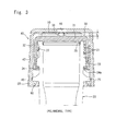
- an inner cap (generally designated at 30) is fitted by screw-engagement onto the mouth portion (generally designated at 20) of a container such as bottle, and an over-cap (generally designated at 40) is fitted onto the inner cap 30.
- a thread 21 is formed at an upper part on the outer surface of the container mouth portion 20, a flange portion 23 is formed on the lower side thereof, and a support ring 25 which is a protuberance having the greatest diameter is formed further on the lower side thereof.
- the inner cap 30 has a top plate 31 and a cylindrical wall 32 descending from the circumferential edge of the top plate.
- a thread 33 is formed on the inner surface of the cylindrical wall 32 as shown in Fig. 3 . Namely, the inner cap 30 is held on the container mouth portion 20 due to the screw-engagement of the thread 33 with the thread 21 on the outer surface of the container mouth portion 20.
- a holder band (or a tamper evidence band) 34 is provided integrally with the cylindrical wall 32 to firmly hold the inner cap 30.
- the holder band 34 is extending up to the lower side of the flange portion 23 on the outer surface of the container mouth portion 20.
- the holder band 34 has an engaging protuberance (or flap piece) 34a formed on the inner surface thereof to engage with the surface on the lower side of the flange portion 23.
- the inner cap 30 is firmly held on the outer surface of the container mouth portion 20 due to the engagement of the engaging protuberance 34a with the flange portion 23.
- the cylindrical wall 32 has a polyhedral outer surface which engages with the inner surface of the over-cap 40 that will be described later.
- An inner ring 35 is provided along the circumferential portion on the lower surface of the top plate 31 of the inner cap 30 maintaining a gap relative to the cylindrical wall 32 (see Fig. 3 ). Namely, the upper end of the container mouth portion 20 enters into a space between the cylindrical wall 32 and the inner ring 35, and the outer surface of the inner ring 35 comes into close contact with the inner surface of the upper end portion of the container mouth portion 20 to assure the sealing of the interior of the container.
- a cutter 36 (protrusion having a sharp end) is formed on the upper surface of the top plate 31 at the central portion thereof.
- the cutter 36 works to break the circuit of the IC tag 10 (e.g., unsealing detector circuit 9 shown in Fig. 1 ) attached to the over-cap 40.
- the over-cap 40 that is fixed being fitted onto the inner cap 30 has a top panel 41 and a skirt 42 descending from the circumferential edge of the top panel 41.
- a polyhedral portion 43 that corresponds to the polyhedral outer surface of the cylindrical wall 32 of the inner cap 30. That is, due to the engagement of the polyhedral portion 43 with the polyhedral outer surface of the cylindrical wall 32 of the inner cap 30, the inner cap 30 is turned accompanying the turn of the over-cap 40.
- the outer surface of the skirt 42 is knurled as designated at 42a to facilitate the turn of the over-cap 40.
- a stopper band 50 is formed at the lower end portion of the skirt 42, and engaging protuberances 55 are formed on the inner surface thereof.
- the engaging protuberances 55 come into engagement with the lower surface of the support ring 25 on the outer surface of the container mouth portion 20 to limit the over-cap 40 from ascending.
- the engaging protuberances 55 come into strong engagement with the lower surface of the support ring 25, the force of engagement thereof being set to be stronger than the force of engagement between the holder band 34 (engaging protuberance 34a) of the inner cap 30 and the flange portion 23.
- the over-cap 40 has a step 45 formed in the inner surface thereof at the boundary between lower end of the skirt 42 and the stopper band 50. Namely, the step 45 comes into engagement with the upper surface of the support ring 25 to limit the over-cap 40 from descending.
- a dent 46 is formed in the lower surface of the top panel 41 at the center thereof to receive a cutter 36 provided on the upper surface of the top plate 31 of the inner cap 30.
- a dent 46 is formed in the lower surface of the top panel 41 at the center thereof to receive a cutter 36 provided on the upper surface of the top plate 31 of the inner cap 30.
- the above-mentioned IC tag 10 is attached as shown in Fig. 4 .
- the IC tag 10 has not been shown in Fig. 5 .
- the IC tag 10 may be attached to the lower surface of the top panel 41 by insertion by adjusting the size of the resin film 1 of the IC tag 10 and fitting it thereto, or by using an adhesive or by heat-sealing.
- the IC tag 10 is so attached that the unsealing detector circuit 9 (or any other circuit portion thereof) is located at the above position.
- the over-cap 40 when the over-cap 40 is provided being fitted onto the inner cap 30 that has been fitted onto the container mouth portion 20, the lower end of the skirt 42 and the engaging protuberance 55 of the band 50 are positioned on the lower side of the support ring 25 on the outer surface of the container mouth portion 20 while the step 45 at the boundary portion between the band 50 and the skirt 42 comes into engagement with the upper surface of the support ring 25. Therefore, a predetermined gap L is maintained between the lower surface of the top panel 41 of the over-cap 40 and the upper surface of the top plate 31 of the inner cap 30. As a result, the IC tag 10 (unsealing detector circuit 9 or other circuit portion) is held without being broken.
- the polyhedral inner surface 43 of the skirt 42 comes in engagement with the outer surface (polyhedral surface) of the cylindrical wall 32 of the inner cap 30, and the inner cap 30, too, turns in a direction in which it is unsealed.
- the inner cap 30 rises along the outer surface of the container mouth portion 20, and the engaging protuberance 34a goes over the flange portion 23 formed on the outer surface of the container mouth portion 20.
- the engaging protuberances 55 of the stopper band 50 are still strongly engaged with the support ring 25 of the container mouth portion 20, preventing it from rising. Therefore, if the over-cap 40 is continuously turned in the direction in which it is unsealed, the cutter 36 of the inner cap 30 pierces through the unsealing detector circuit 9 (or other circuit portion thereof) of the IC tag 10 attached to the over-cap 40.
- the over-cap 40 is pushed up by the inner cap 30, whereby the engaging protuberances 55 of the band 50 go beyond the support ring 25 of the container mouth portion 20 and, therefore, the over-cap 40 rises together with the inner cap 30 and is removed from the container mouth portion 20 in a state of being fitted onto the inner cap 30.
- the inner cap 30 and the over-cap 40 thus removed from the container mouth portion 20 can be fitted again onto the container mouth portion 20 to reseal it in a state where the over-cap 40 is being fitted onto the inner cap 30. Or, the over-cap 40 may be taken away, and the inner cap 30 only may be used again to reseal the container mouth portion 20.
- the circuit portion is broken in the IC tag 10 that is attached to the over-cap 40.
- the unsealing detector circuit 9 is broken, for example, none of the IC chip 3, the antenna 5 and the lead wires 7 has been broken, permitting information stored in the IC chip 3 to be read out by using an external reader unit.
- the information includes such information that the unsealing detector circuit 9 has been broken. If the antenna 5 is broken, then no information can be read out from the IC chip 3 as a matter of course.
- the composite container lid provides excellent function for preventing tampering and is capable of effectively preventing unauthorized use such as exchanging the content by recognizing the fact of unsealing.
- the IC tag 10 can also be attached to the upper surface of the top plate 31 of the inner cap 30.
- the cutter 36 is provided on the lower surface of the top panel 41 of the over-cap 40, and the dent 46 is formed in the upper surface of the top plate 31 at the center thereof to receive the cutter 36.
- the over-cap is simply turned in a direction in which it is unsealed to break the IC tag 10 (unsealing detector circuit 9 or other circuit portion thereof) and to remove (unseal) the inner cap 30 from the container mouth portion 20.
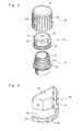
- the composite container lid of this type has an inner cap 30 fitted by screw-engagement onto the container mouth portion 20, and has an over-cap 40 fitted onto the inner cap 30.
- a thread 21, a flange portion 23 and a support ring 25 are formed on the outer surface of the container mouth portion 20 in this order from the upper side.
- the inner cap 30 has a top plate 31 and a cylindrical wall 32 descending from the circumferential edge of the top plate.
- a thread 33 is formed on the inner surface of the cylindrical wall 32 so as to come in screw-engagement with a thread 21 on the outer surface of the container mouth portion 20 as shown in Fig. 6 .
- the inner cap 30 is held on the container mouth portion 20 due to the screw-engagement.
- An inner ring 35 is provided along the circumferential portion on the lower surface of the top plate 31 of the inner cap 30 maintaining a gap relative to the cylindrical wall 32 (see Fig. 6 ). Namely, like the above-mentioned one of the polyhedrally engaging type, the upper end of the container mouth portion 20 enters into a space between the cylindrical wall 32 and the inner ring 35, and the outer surface of the inner ring 35 comes into close contact with the inner surface of the upper end portion of the container mouth portion 20 to assure the sealing.
- a cutter 36 is formed on the upper surface of the top plate 31 at the central portion thereof.
- the cutter 36 works to break the unsealing detector circuit 9 of the IC tag 10 attached to the over-cap 40.
- a thread 37 is provided on the outer surface of the cylindrical wall 32 of the inner cap 30 to come in screw-engagement with the over-cap 40.
- the cylindrical wall 32 is, further, forming a flaring portion 32a at its lower part.
- the over-cap 40 has a top panel 41 and a skirt 42 descending from the circumferential edge of the top panel 41.
- the screw-engagement has an inverse relationship to the screw-engagement between the inner surface of the inner cap 3 0 and the outer surface of the container mouth portion 2 0 (screw engagement between the thread 21 and the thread 33).
- the direction of turn in which the screw-engagement is released between the over-cap 40 and the inner cap 30 is a direction of turn in which the screw-engagement is tightened between the inner cap 30 and the container mouth portion 20
- the direction of turn in which the screw-engagement is tightened between the over-cap 40 and the inner cap 30 is a direction of turn in which the screw-engagement is released between the inner cap 30 and the container mouth portion 20.
- the skirt 42 is forming a step portion 48 that is slightly protruding inward at the lower end on the inner surface thereof.
- the step portion 48 engages with the lower end of the flaring portion 32a of the cylindrical wall 32 of the inner cap 30 effectively preventing the over-cap 40 from escaping.
- a stopper band 50 is coupled to the lower end of the skirt 42 via a bridging portion 51 that can be torn off, and a grip 53 is provided on the outer surface of the band 50 so as to be nipped when it is to be torn off. That is, upon pulling the grip 53 in a circumferential direction, the bridging portion 51 is torn off and the stopper band 50 can be easily torn off from the skirt 42.
- Fig. 8 shows the over-cap 40 in a state where the stopper band 50 has been torn off.
- the stopper band 50 has, in the inner surface thereof, a slightly dented surface 50a and, further, has an engaging protuberance 55 at the lower end thereof.
- the step 48 at the lower end on the inner surface of the skirt 42 engages with the flaring portion 32a of the cylindrical wall 32 limiting the over-cap 40 from ascending while as the engaging protuberance 55 engages with the lower surface of the support ring 25 on the outer surface of the container mouth potion 20, the over-cap 40 is limited from descending.
- the top panel 41 has a dent 46 formed in the lower surface and at the center thereof to receive the cutter 36 provided on the upper surface of the top plate 31 of the inner cap 30, and has the IC tag 10 attached thereto (see Fig. 6 ).
- Fig. 8 shows neither the IC tag 10 nor the knurling 42a described above.
- the IC tag 10 may be attached to the lower surface of the top panel 41 by mechanical means such as insertion depending on its size, or may be attached by using an adhesive or by heat-sealing.
- the IC tag 10 is so attached that the unsealing detector circuit 9 of the IC tag 10 is located on a position above the dent 46.
- the stopper band 50 (dented surface 50a and engaging protuberance 55) engages with the container mouth portion 20 (support ring 25), whereby a predetermined gap L is maintained between the lower surface of the top panel 41 of the over-cap 40 and the upper surface of the top plate 31 of the inner cap 30, and the over-cap 40 is so held that the IC tag 10 (unsealing detector circuit 9) will not be broken.
- the grip 53 is nipped and is torn off to separate the stopper band 50 away from the over-cap 40 (skirt 42). This permits the over-cap 40 to ascend.
- the over-cap 40 descends in a direction in which it is tightened relative to the inner cap 30 due to the screw-engagement between the thread 47 on the inner surface of the skirt 42 and the thread 37 of the inner cap 30 (which is in an inverse relationship relative to the screw-engagement between the cap 30 and the container mouth portion).
- the inner cap 30 turns in the direction in which it is unsealed, liberated from the screw-engagement with the container mouth portion 20, and ascends relative to the container mouth portion 20.
- the over-cap 40 is continuously turned in the direction in which it is unsealed, the cutter 36 provided on the top plate 31 of the inner cap 30 pierces through the unsealing detector circuit 9 of the IC tag 10 attached to the over-cap 40. If further turned, the over-cap 40 ascends together with the inner cap 30, and is removed from the container mouth portion 20 in a state of being fitted onto the inner cap 30.
- the inner cap 30 and the over-cap 40 thus removed from the container mouth portion 20 can be fitted again onto the container mouth portion 20 to reseal it in a state where the over-cap 40 is being fitted onto the inner cap 30. Or, the over-cap 40 may be taken away, and the inner cap 30 only may be used again to reseal.
- the unsealing detector circuit 9 is broken in the IC tag 10 that is attached to the over-cap 40.
- the antenna 5 and the lead wires 7 has been broken, permitting information stored in the IC chip 3 to be read out by using an external reader unit.
- the information includes such information that the unsealing detector circuit 9 has been broken.
- the packing body provides excellent function for preventing tampering and is capable of effectively preventing unauthorized use such as exchanging the content by recognizing the fact of unsealing.
- the IC tag 10 can also be attached to the upper surface of the top plate 31 of the inner cap 30.
- the protuberance 36 that serves as a cutter is provided on the lower surface of the top panel 41 of the over-cap 40, and the dent 46 is formed in the upper surface of the top plate 31 at the center thereof to receive the cutter 36.
- the composite container lid of the above inversely threaded type cannot be unsealed unless the stopper band 50 is cut off. Therefore, the unsealing is detected relying on both the breakage of the IC tag 10 (unsealing detector circuit 9) and the separation of the stopper band 50 contributing greatly to improving the function of guaranteeing the quality of the content.
- the structure of the composite container lid of the inversely threaded type by taking an example of breaking the unsealing detector circuit 9 in the IC tag 10.
- the IC tag 10 may be so positioned that the antenna 5 is located at the central portion. In this case, the unsealed fact can be recognized since information can no longer be read out from the IC chip 3.
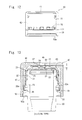
- the composite container lid of the ratchet type too, has an inner cap 30 fitted by screw-engagement onto the container mouth portion 20, and has an over-cap 40 fitted onto the inner cap 30.
- the outer surface of the container mouth portion 20, too, is like those of the above-mentioned composite container lids of the polyhedrally engaging type and the inversely threaded type, and a thread 21, a flange portion 23 and a support ring 25 are formed in this order from the upper side.
- the inner cap 30 has a top plate 31 and a cylindrical wall 32 descending from the circumferential edge of the top plate.
- a thread 33 is formed on the inner surface of the cylindrical wall 32 so as to come in screw-engagement with a thread 21 on the outer surface of the container mouth portion 20 as shown in Fig. 10 .
- the inner cap 30 is held on the container mouth portion 20 due to the screw-engagement.
- An inner ring 35 is provided along the circumferential portion on the lower surface of the top plate 31 maintaining a gap relative to the cylindrical wall 32.
- the upper end of the container mouth portion 20 enters into a space between the cylindrical wall 32 and the inner ring 35, and the outer surface of the inner ring 35 comes into close contact with the inner surface of the upper end poriton of the container mouth portion 20 to assure the sealing.
- a vertical groove 70 is formed in the outer surface of the cylindrical wall 32 stretching down in the vertical direction from the upper end thereof, and a ratchet groove 73 having an end is formed stretching from the lower end of the vertical groove 70 in a circumferential direction in which the inner cap 30 is unsealed. That is, in the composite container lid of the ratchet type, the inner cap 30 is unsealed by the over-cap 40 relying on the engagement which uses the ratchet groove 73.
- the IC tag 10 is stuck by using an adhesive from the upper surface of the top plate 31 of the inner cap 30 over to the outer surface of the cylindrical wall 32 and, particularly, in a manner to cover the ratchet groove 73. Namely, the IC tag 10 is broken as a cutting pawl 75 that will be described below passes through the ratchet groove 73. Therefore, the IC tag 10 is so attached that the circuit (unsealing detector circuit 9) that is to be broken is located on the ratchet groove 73.
- the IC tag 10 usually, assumes a rectangular shape.
- the over-cap 40 has a top panel 41 and a skirt 42 descending from the circumferential edge of the top panel 41.
- a stopper band 50 To the lower end of the skirt 42 is linked a stopper band 50 via a bridging portion 51 that can be torn off like that of the composite container lid of the inversely threaded type described above.
- a grip 53 On the outer surface of the band 50 is provided a grip 53 that can be nipped to tear it off.
- the bridging portion 51 is turn off, and the stopper band 50 is easily torn off from the skirt 42.
- a dented surface 50a is formed in the inner surface of the stopper band 50. As will be understood from Fig. 10 , the support ring 25 is fitted in the dented surface 50a limiting the over-cap 40 from further descending.
- flap pieces 75 are formed on the inner surface of the skirt 42 at the lower end thereof.
- the flap pieces 75 engage with the lower end surface of the skirt 32 of the inner cap 30, forming a predetermined gap between the top plate 31 of the inner cap 30 and the top panel 41 of the over-cap 40 and preventing the over-cap 40 from escaping.
- a cutting pawl 77 is provided at an upper part on the inner surface of the skirt 42 of the over-cap 40.
- the cutting pawl 77 is fitted in the above-mentioned vertical groove 70 formed in the outer surface of the cylindrical wall 32 of the inner cap 30.
- the over-cap 40 is mounted being fitted onto the inner cap 30 that has been fitted to the container mouth portion 20.
- the over-cap 40 is so positioned that the cutting pawl 77 engages with the vertical groove 70.
- a vertical rib for positioning may be formed on the outer surface of the skirt 42 of the over-cap 40 being corresponded to the position of the cutting pawl 77.
- the operation for unsealing the composite container lid of the ratchet type having the above structure starts with tearing the stopper band 53 off by nipping the grip 53. That is, the stopper band 50 is cut off from the over-cap 40 (skirt 42) which is then permitted to descend. By pushing the over-cap 40 in, therefore, the cutting pawl 77 enters into the ratchet groove 73 that is extending in the unsealing direction.
- the cutting pawl 77 comes in contact with the end portion 73a of the ratchet groove 73 whereby the inner cap 30, too, turns together wi th the over-cap 40 in the unsealing direction, and is released from the screw-engagement with the container mouth portion 20. Namely, the inner cap 30 is removed from the container mouth portion 20 in a manner that the over-cap 40 is being fitted onto the inner cap 30.
- the inner cap 30 and the over-cap 40 thus removed from the container mouth portion 20 can be fitted again onto the container mouth portion 20 to reseal it in a state where the over-cap 40 is being fitted onto the inner cap 30. Or, the over-cap 40 may be taken away, and the inner cap 30 only may be used again to reseal.
- the above-mentioned composite container lid of the ratchet type is capable of selectively breaking the unsealing detector circuit 9 without breaking the IC chip 3, antenna 5 or lead wires 7. Therefore, even if the inner cap 30 is fitted onto the container mouth portion 20 to reseal it with the over-cap 40 being fitted thereon; a general customer is allowed to correctly read and recognize the fact of unsealing upon reading information from the IC chip 3 by using, for example, a cell phone.
- the packing body provides excellent function for preventing tampering and is capable of effectively preventing unauthorized use such as exchanging the content by recognizing the fact of unsealing.
- the composite container lid of the ratchet type clearly indicates the fact of unsealing based on the tear off of the stopper band 50 in addition to the breakage of the IC tag 10 (unsealing detector circuit 9) and, therefore, has a very excellent function for guaranteeing the quality of the content.
- the above-mentioned composite container lid shown in Figs. 10 to 12 has the structure in which the unsealing detector circuit 9 is broken at the time of unsealing.
- the IC tag 10 is so arranged that the circuit inclusive of the antenna 5 (e.g. , inclusive of lead wires 7 and antenna 5) is broken at the time of unsealing, then no information can be read out from the IC chip 3 after the container mouth portion 20 is unsealed, and from which it is allowed to recognize the fact that the container mouth portion 20 has been unsealed.
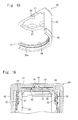
- the composite container lid of the fitting type too, has an inner cap 30 fitted onto the container mouth portion 20 by screw-engagement, and an over-cap 40 is fitted onto the inner cap 30.
- the outer surface of the container mouth portion 20 is the same as those of the packing containers of the polyhedrally engaging type and the inversely threaded type mentioned above, and has a thread 21, a flange portion 23 and a support ring 25 formed thereon in this order from the upper side.
- the inner cap 30 has a top plate 31 and a cylindrical wall 32 descending from the circumferential edge of the top plate.
- a thread 33 is formed on the inner surface of the cylindrical wall 32 so as to come in screw-engagement with a thread 21 on the outer surface of the container mouth portion 20 as shown in Fig. 13 .
- the inner cap 30 is held on the container mouth portion 20 due to the screw-engagement.
- the outer surface of the cylindrical wall 32 is knurled in the upper part thereof so that it can be easily turned by hand at the time of releasing, i. e., at the time of unsealing and sealing the inner cap 30.
- the lower part of the cylindrical wall 32 is flaring as designated at 32a.
- An inner ring 35 is provided along the circumferential edge portion on the lower surface of the top plate 31 of the inner cap 30 maintaining a gap relative to the cylindrical wall 32 (see Fig. 13 ).
- the upper end of the container mouth portion 20 enters into a space between the cylindrical wall 32 and the inner ring 35, and the outer surface of the inner ring 35 comes into close contact with the inner surface of the upper end portion of the container mouth portion 20 to assure the sealing.
- a cutter 36 is formed on the upper surface of the top plate 31 at the central portion thereof. The cutter 36 works to break the unsealing detector circuit 9 of the IC tag 10 attached to the over-cap 40.
- notches 60 for fitting are formed in the circumferential edge portion on the upper surface of the top plate 31 maintaining a suitable distance.
- the over-cap 40 has a top panel 41 and a skirt 42 descending from the circumferential edge of the top panel 41.
- the skirt 42 is forming a step portion 48 that is slightly protruding inward at the lower end on the inner surface thereof.
- the step portion 48 engages with the lower end of the flaring portion 32a of the cylindrical wall 32 of the inner cap 30 effectively preventing the over-cap 40 from escaping.
- a stopper band 50 is coupled to the lower end of the skirt 42 via a bridging portion 51 that can be torn off, and a grip 53 is provided on the outer surface of the band 50 so as to be nipped when it is to be torn off.
- the bridging portion 51 is torn off and the stopper band 50 can be easily torn off from the skirt 42.
- the stopper band 50 has, in the inner surface thereof, a dented surface 50a. As will be understood from Fig. 13 , the support ring 25 enters into the dented surface 50a limiting the over-cap 40 from further descending.
- the top panel 41 has a dent 46 formed in the lower surface and at the center thereof to receive the cutter 36 provided on the upper surface of the top plate 31 of the inner cap 30, and has the IC tag 10 attached thereto (see Fig. 13 ).
- the IC tag 10 has not been shown in Fig. 15 .
- the IC tag 10 may be attached to the lower surface of the top panel 41 by mechanical means such as insertion depending on its size, or may be attached by using an adhesive or by heat-sealing.
- the IC tag 10 is so attached that the unsealing detector circuit 9 of the IC tag 10 is positioned above the dent 46.
- top panel 41 has, on the lower surface and along the circumferential edge portion thereof, fitting bumps 62 so as to be corresponded to the fitting notches 60 of the inner cap 30 ( Fig. 15 ).
- the caps 30 and 40 are fitted onto the container mouth portion 20, the over-cap 40 being fitted onto the inner cap 30.
- the fitting dents 62 have been so set as to be positioned on the fitting notches 60.
- a predetermined gap L is maintained between the inner surface of the top panel 41 of the over-cap 40 and the upper surface of the top plate 31 of the inner cap 30 so that the IC tag 10 (e.g., unsealing detector circuit 9) will not be broken.
- the grip 53 is nipped and is torn off to separate the stopper band 50 away from the over-cap 40 (skirt 42) in the same manner as that of the above-mentioned composite container lid of the inversely threaded type. This permits the over-cap 40 to descend.
- the fitting bumps 62 fit into the fitting notches 60 and, at the same time, the protuberance (cutter) 36 provided on the top plate 31 of the inner cap 30 pierces through the unsealing detector circuit 9 of the IC tag 10 attached to the top panel of the over-cap 40 and enters into the dent 46.
- the inner cap 30 is removed from the container mouth portion 20 with the over-cap 40 being fitted thereon.
- the inner cap 30 and the over-cap 40 thus removed from the container mouth portion 20 can be fitted again onto the container mouth portion 20 to reseal it in a state where the over-cap 40 is being fitted onto the inner cap 30. Or, the over-cap 40 may be taken away, and the inner cap 30 only may be used again to reseal.
- the unsealing detector circuit 9 is broken in the IC tag 10 that is attached to the over-cap 40.
- the antenna 5 and the lead wires 7 has been broken, permitting information stored in the IC chip 3 to be read out by using an external reader unit.
- the information includes such information that the unsealing detector circuit 9 has been broken.
- the packing body provides excellent function for preventing tampering and is capable of effectively preventing unauthorized use such as exchanging the content by recognizing the fact of unsealing.
- the IC tag 10 can also be attached to the upper surface of the top plate 31 of the inner cap 30.
- a cutter 36 is provided on the top panel 41 of the over-cap 40, and a dent 46 is formed in the upper surface of the top plate 31 at the center thereof to receive the protuberance 36.
- the unsealing is detected relying on both the breakage of the IC tag 10 (unsealing detector circuit 9) and the tear off of the stopper band 50, offering a very excellent function for guaranteeing the quality of the content.
- the over-cap 40 is, first, fitted onto the inner cap 30.
- the fitting bumps 62 are set to be positioned between the fitting dents 60 by using the positioning ribs. This prevents the over-cap 40 (fitting bumps 62) from deeply descending and, therefore, reliably prevents the IC tag 10 from being broken.
- the inner cap 30 is fitted onto the container mouth portion 20 with the over-cap 40 being fitted thereon as described above.
- the over-cap 40 is turned in the sealing direction, and the fitting bumps 62 are set to be positioned on the fitting bumps 60 by utilizing the positions of the positioning ribs mentioned above to thereby assemble the packing container of the fitting type having the structure as shown in Fig. 13 .
- the IC tag 10 may be so positioned that the antenna 5 is located at the central portion. In this case, the fact of unsealing can be recognized as no information is read out from the IC chip 3.
- the composite container lid of the above-mentioned fitting type can be designed and modified in various other ways.
- the over-cap 40 is provided with a resilient strip to effectively prevent accidental breakage of the circuit of the IC tag 10 while the composite container lid is being assembled or being fitted onto the container mouth portion.
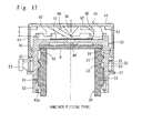
- Figs.17 to 21 show the structure of the composite container lid of the fitting type provided with the resilient strip.
- this composite container lid too, has the basic structure similar to that of the above composite container lid of Figs. 13 to 16 .
- the inner cap 30 is fitted onto the container mouth portion 20 by screw-engagement, and the over-cap 40 is fitted onto the inner cap 30.
- a thread 33 is formed on the inner surface of the cylindrical wall 32 of the inner cap 30 to come into screw-engagement with the thread 21 on the outer surface of the container mouth portion 20.
- the inner cap 30 is held on the container mouth portion 20 due to the screw-engagement.
- a tamper evidence band (TE band) 83 is provided at the lower end of the cylindrical wall 32 via a bridge 81 that can be broken, and a protruding piece 83a formed on the inner surface of the TE band 83 engages with the lower surface of the flange portion 23 formed on the outer surface of the container mouth portion 20 limiting the inner cap 30 from ascending.
- the composite container lid of this type is provided with a packing P which is for closing the upper end of the container mouth portion 20, the packing P coming in close contact with the upper end of the container mouth portion being pushed by the lower surface of the top plate 31 of the inner cap 30 thereby to seal the container mouth portion 20.
- a small protuberance 85 is formed on the inner surface of the cylindrical wall 32 at an upper part thereof.
- the small protuberance 85 enables the packing P to be held in the inner cap 30 and, further, makes it possible to remove the inner cap 30 from the container mouth portion 20 and, at the same time, to tear the packing P off from the upper end of the container mouth portion 20.
- a cutter 36 is provided on the central portion of the top panel 41 of the over-cap 40, and being corresponded to the cutter 36, a dent 46 is formed in the upper surface of the top plate 31 of the inner cap 30 at the central portion thereof to receive an end portion of the cutter 36.
- An IC tag 10 is provided so as to cover the dent 46.
- the cutter 36 breaks a circuit portion (e.g., unsealing detector circuit 9) that connects to the IC chip of the IC tag 10.
- fitting notches 60 are formed in the peripheral edge portion on the upper surface of the top plate 31 of the inner cap 30 maintaining a suitable distance, and bumps 62 are formed in the circumferential edge portion on the lower surface of the top panel 41 of the over-cap 40 being corresponded to the notches 60. That is, upon pushing the over-cap 40 down to push the bumps 62 into the notches 62 so as to engage therewith, the inner cap 30 can be turned accompanying the turn of the over-cap 40.
- a stopper band 50 is coupled to the lower end of the skirt 42 via a bridging portion 51 that can be torn off, and a grip 53 is provided on the outer surface of the band 50 so as to be nipped when it is to be torn off. That is, upon pulling the grip 53 in a circumferential direction, the bridging portion 51 is torn off and the stopper band 50 can be easily torn off from the skirt 42.
- resilient strips 90 are provided on the lower surface of the top panel 41 of the over-cap 40.
- the resilient strips 90 are facing downward from the lower surface of the top panel 41 and facing toward the direction in which the over-cap 40 is sealed, and have their ends press-contacting to the upper surface of the top plate 31 of the inner cap 30. Therefore, the over-cap 40 fitted onto the inner cap 30 is urged upward by the resilient strips 90.
- the resilient strips 90 are provided in a number of four (see Fig. 20 ).
- strip-engaging protuberances 91 are provided being corresponded to the resilient strips 90 to engage with the ends of the resilient strips 90. That is, if the over-cap 40 is turned in the sealing direction, the inner cap 30, too, turns in the sealing direction due to the engagement between the ends of the resilient strips 90 and the strip-engaging protuberances 91.
- the composite container lid of this structure is assembled, is mounted onto the container mouth portion 20, and is unsealed as described below.
- the over-cap 40 is fitted upon being fitted onto the inner cap 30.
- the stopper band 50 of the over-cap 40 descends along the outer surface of the cylindrical side wall 32 of the inner cap 30 whereby the lower end of the stopper band 50 comes in contact with the positioning rib 97 limiting the over-cap 40 from descending any more.
- the engaging protuberance 99 of the over-cap 40 is located between the positioning circumferential protuberances 93 and 95 of the inner cap 30.
- the over-cap 40 In a state where the over-cap 40 is fitted onto the inner cap 30, the over-cap 40 is prevented from rattling due to the resilient strips 90 and is, further, urged thereby upward. Therefore, the engaging protuberance 99 engages with the lower surface of the upper positioning circumferential protuberance 93 limiting the over-cap 40 from ascending and, as a result, maintaining a predetermined gap L between the top panel 41 of the over-cap 40 and the top plate of the inner cap 30. In this state, therefore, the IC tag 10 is effectively prevented from being broken by the cutter 46.
- the inner cap 30 is put on the container mouth portion 20 and the over-cap 40 is turned in the sealing direction so that the inner cap 30 is fitted onto the container mouth portion 20. That is, upon turning the over-cap 40 in the sealing direction, the ends of the resilient strips 90 come in engagement with the strip-engaging protuberances 91, and the inner cap 30, too, turns in the sealing direction together with the over-cap 40.
- the operation for unsealing the composite container lid thus fitted onto the container mouth portion 20 is basically the same as that of the case of the above-mentioned composite container lid shown in Fig. 13 .
- the stopper band 50 is torn off from the over-cap 40 (skirt 42).
- the over-cap 40 is now allowed to descend.
- the over-cap 40 is pushed in causing the fitting bumps 62 to be fitted into the fitting notches 60.
- the cutter 36 that descends pierces through the IC tag 10 (circuit such as unsealing detector circuit 9) provided on the top plate 31 of the inner cap 30, and enters into the dent 46.
- the engaging protuberance 99 of the over-cap 40 goes beyond the lower positioning circumferential protuberance 95 and moves toward the lower side of the circumferential protuberance 95.
- the over-cap 40 has been urged upward due to the resilient strips 90.
- the engaging protuberance 99 comes in engagement with the lower surface of the lower circumferential protuberance 95 limiting the over-cap 40 from ascending. That is, though being urged upward by the resilient strips 90, the over-cap 40 is limited from ascending and, therefore, a stable engagement is maintained between the fitting bumps 62 and the fitting notches 60.
- the over-cap 40 is turned in the unsealing direction in a state where the IC tag 10 has been broken, the inner cap 30, too, turns in the unsealing direction since the bumps 62 have been engaged with the notches 60. Therefore, the screw-engagement is released between the inner cap 30 and the container mouth portion 20, and the inner cap 30 is removed from the container mouth portion 20 in such a form that the over-cap 40 has been fitted thereon.
- the inner cap 30 removed from the container mouth portion 20 can be used for resealing with the over-cap 40 being fitted thereon or without the over-cap 40.
- the number of the resilient strips 90 there is no specific limitation on the number of the resilient strips 90, and the number thereof may be one. From such a standpoint that the resilient force of the resilient strips 90 is evenly applied to the over-cap 40, however, it is desired that the resilient strips 90 are provided in a number of 2 to 4 and, specifically, 3 or 4.
- the above composite container lid may, further, assume the structure as shown in Fig. 22 .
- the composite container lid of the fitting type of Fig. 21 is the same as the composite container lid of Fig. 17 except that the cylindrical side wall 32 of the inner cap 30 is divided, by a slit 100 extending from the upper side, into an inner side wall 32a and an outer side wall 32b, the lower end of the outer side 32b protruding outward to form a positioning rib 97, and the step 45 formed on the inner surface of the stopper band 50 coming in engagement with the positioning rib 97 to limit the over-cap 40 from descending.
- the lower end of the outer side wall 32b is coupled to the inner side wall 32a at a portion that is not shown. Namely, the slit 100 is not penetrating up and down through the coupling portion and is terminating near the lower end.
- a TE band 83 is provided at the lower end of the inner side wall 32a of the cylindrical side wall 32 , and the stopper band 50 of the over-cap 40 is so formed as to cover the TE band 83. Therefore, the stopper band 50 protects the TE band 83 effectively preventing such an unauthorized unsealing that the composite container lid is removed from the container mouth portion 20 by inserting a tool such as screw driver from the lower end of the TE band 83 and, further, improving the function for guaranteeing the quality of the content.
- the composite container lid can be assembled and fitted onto the container mouth portion 20 or can be removed therefrom in quite the same manner as that of the case of the composite container lid of Fig. 17 .
- the cutter 36 is provided on the inner cap 30 or on the over-cap 40 at the center thereof except the composite container lid of the ratchet type.
- the cutter 36 can also be provided at a position deviated from the center.
- the composite container lid of the type in which the cutter is arranged at a position deviated from the center is specifically desired for breaking the antenna 5 of the IC tag 10 of the form shown in Fig. 2 .
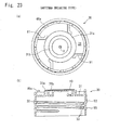
- the structure of the inner cap 30 of the composite container lid of the antenna breaking type is shown in Figs. 23(a) and (b)
- the structure of the over-cap 40 is shown in Figs. 24(a) and (b) .
- a protruded central portion 31a is formed on the upper surface of the top plate 31 of the inner cap 30 used for the composite container lid, an annular dent 31b is formed in the central portion 31a so as to surround the center O, and the IC tag 10 is attached so as to cover the annular dent 31b. That is, the annular dent 31b corresponds to the dent 46 that receives the cutter 36 in the composite container lids of various types mentioned above.
- a plurality of cutters 36 are formed on the lower surface of the top panel 41 of the over-cap 40 used for the composite container lid in a manner to surround the center O.
- the positions of the cutters 36 are corresponding to the annular dent 31b.
- the cutters 36 are all positioned over the annular dent 31b. If the over-cap 40 descends, therefore, the cutters 36 all pierce through the IC tag 10 and the ends of the cutters 36 are received in the annular dent 31b.
- the ends (lower ends) 101 of the cutters 36 that are used have the shape of a sharp blade (thin plate-like shape with the end as the vertex) at their ends 36' and edges 36" and, specifically, that as shown in Fig. 26 , bottom drawing (C), have the shape consisting of two pieces of blades 3 6a and 3 6b crossing each other.
- the ends 36' thereof may simply push and widen the arcuate lines 5a, 5a when they are supposed to pierce through between the arcuate lines 5a and 5a forming the multiplicity of line portions Y of the IC tag 10 of Fig. 2 to break them without, however, really breaking the lines 5a, 5a.
- the cutters 36 having the shape of sharp blades at their ends 36' and edges 36" on the other hand, it is made possible to reliably cut the arcuate lines 5a forming the multiplicity of line portions Y.
- the lines 5a can be reliably broken irrespective of the positions of the multiplicity of line portions Y pierced through by the ends 36' of the cutters 36.
- the cutters 36 were provided in a number of four in the above embodiment, the number should be at least two or more and, specifically, three or more so that the multiplicity of line portions Y of the antenna 5 can be reliably broken.
- the plurality of cutters 36 are arranged along a circle with the center O of the over-cap 40 as a center. It is, however, also allowable to arrange a plurality of cutters 36 at positions away from the center O by dissimilar distances.
- the inner surface of the cylindrical wall 32 of the inner cap 30 is threaded as designated at 33 to engage with the thread of the container mouth portion like that of the above-mentioned composite container lids of Figs. 17 to 22 , and its outer surface is forming circumferential protuberances 93 and 95 for positioning maintaining a distance in the up-and-down direction. Further, an engaging protuberance 99 is formed on the outer surface of the skirt 42 of the over-cap 40.
- a plurality (four) of resilient strips 90 are formed on the lower surface of the top panel 41 of the over-cap 40, while on the upper surface of the top plate 31 of the inner cap 30 are formed engaging protuberances 91 that come into engagement with the ends of the resilient strips 90 to block the turn of the resilient strips 90 (over-cap 40) relative to the inner cap 30. Namely, if the over-cap 40 is turned in the sealing direction, the inner cap 30, too, turns in the sealing direction due to the engagement of the ends of the resilient strips 90 with the engaging protuberances 91.
- protuberances 60a are formed maintaining a suitable distance along the whole circumference of the edge portion on the upper surface of the top plate 31 of the inner cap 30 to engage with the over-cap 40, while protuberances 62a are formed on the circumferential edge portion of the top panel 41 of the over-cap 40 to engage with the above protuberances 60a.
- the protuberances 60a of the inner cap 30 have such a triangular shape that a surface is erected on the side in the sealing direction and a surface tilted on the side in the unsealing direction
- the protuberances 62a of the over-cap 40 have such a triangular shape that a surface is erected on the side in the unsealing direction and a surface is tilted on the side in the sealing direction.
- the over-cap 40 is stably held on the inner cap 30 without rattling.
- the over-cap 40 has been urged upward at all times, a gap is maintained between the top panel 41 of the over-cap 40 and the top plate of the inner cap 30 to such a degree that the IC tag 10 is not broken by the cutters 46.
- the over-cap 40 is not pushed in to bring the protuberances 60a and 62a into engagement with each other, then the inner cap 30 cannot be turned in the unsealing direction to thereby exhibit child resistance.
- the protuberances 62a are formed along the circumferential edge portion of the top panel 41 of the over-cap 40 not over the whole circumference of the edge portion but over half the circumference thereof. Therefore, when the over-cap 40 is fitted being fitted onto the inner cap 30, a half of the circumferential edge portion (where no protuberance 62a has been formed) of the top panel 41 of the over-cap 40 comes into direct contact with the protuberances 60a.
- the over-cap 40 is tilted and, as a result, the engaging protuberance 99 on the inner surface of the skirt 42 of the over-cap 40 moves smoothly passing beyond the circumferential protuberance 93 on the outer surface of the cylindrical wall 32 of the inner cap 30, and is located between the circumferential protuberance 93 of the upper side and the circumferential protuberance 95 of the lower side.
- the over-cap 40 thus fitted onto the inner cap 30 is prevented from ascending due to the engagement of the engaging protuberance 99 with the circumferential protuberance 93 of the upper side, and is not allowed to escape from the inner cap 30.
- the inner cap 30 fitted with the over-cap 40 is fitted onto the container mouth portion 20 (not shown in Fig. 23 or 24 ) and if the over-cap 40 is turned in the sealing direction, then the inner cap 30, too, turns in the sealing direction together with the over-cap 40 due to the engagement of the resilient strips 90 with the engaging protuberances 91. Therefore, though the inner cap 30 is fitted onto the container mouth portion 50, the over-cap 40 is limited from descending due to the engagement of the engaging protuberances 55 with the support ring 25.
- a stopper band 50 having a nip 53 is provided at the lower end of the skirt 42 of the over-cap 40 via a bridging portion 51 that can be broken, and an engaging protuberance 55 is formed on the inner surface of the band 50.
- the engaging protuberance 55 engages with the upper surface of the support ring 25 of the container mouth portion 20, and is blocked from moving down.
- the grip 53 is nipped and is pulled to separate the stopper band 50 away enabling the over-cap 40 to descend.
- the over-cap 40 may be pushed in and turned in the unsealing direction. Namely, upon descending the over-cap 40, the protuberances 60a and 62a come into engagement with each other whereby the inner cap 30 turns in the unsealing direction and ascends.
- the over-cap 40 is prevented from ascending due to the engagement of the circumferential protuberance 95 on the lower side with the engaging protuberance 99. Therefore, the inner cap 30 only ascends, and the antenna 5 of the IC tag 10 is broken by the cutters 36.
- the over-cap 40 is, further, turned, the inner cap 30 is removed from the container mouth portion 20, the inner cap 30 mounting thereon the over-cap 40 from which the stopper band 50 has been separated away.
- the over-cap 40 is pushed in and is turned in the unsealing direction, whereby the antenna 5 of the IC tag 10 is effectively broken and, thereafter, the inner cap 30 is removed from the container mouth portion 20. Therefore, if the container mouth portion 20 is once unsealed, information stored in the IC chip 3 can no longer be read out and from which it is allowed to know the fact of unsealing. Moreover, the stripper band 50 of the over-cap 40 that has been separated away makes it possible to learn the fact of unsealing contributing greatly to improving the function for proving the history of unsealing.
- the composite container lid of the antenna breaking type can be designed in various ways.
- a fitting structure provided with bumps and dents for fitting a polyhedrally engaging structure provided with a polyhedral portion 43, and an inversely threaded structure in which the over-cap 40 is fitted onto the inner cap 30 via inverse threads.
- the IC tag 10 is attached to the over-cap 40 or the inner cap 30; i.e., the IC tag 10 is not attached spanning across different members or is not attached to the band portion that will be cut away at the time of unsealing.
- This facilitates the operation for attaching the IC tag 10, facilitates the operation for fitting the inner cap 30 and the over-cap 40 and, besides, effectively prevents the IC tag from being broken during these operations.
- the inner cap 30 sealing the container mouth portion 20 is unsealed being linked to the operation of unsealing the over-cap 40; i.e., no extra operation is needed for unsealing the container mouth portion.
- the above-mentioned composite container lids of the invention can, further, be effectively applied to the existing packing containers to which a cap has been fitted already.
- split molds 210 and 210 having outer surfaces corresponding to the above-mentioned container mouth portion 20 are fitted onto the nozzle portion of an existing packing container 205 which has been filled with the content and to which a cap 200 has been fitted.
- the inner cap 30 and the over-cap 40 of any of the above-mentioned types are provided enabling the composite container lid of the invention to be applied to the existing packing container 205.
- the inner cap 30 and the over-cap 40 are removed in a manner as described above, the split molds 210 and 210 are removed and, further, the cap 200 is removed in a customary manner to take out the content from the container.
- the inner cap 30 and the over-cap 40 of any of the above various types can be produced by compression-forming or inj ection-forming a thermoplastic resin which may be an olefin resin such as polyethylene, polypropylene, ethylene-propylene copolymer, polybutene-1, ethylene-butene-1 copolymer, propylene-butene-1 copolymer or ethylene-vinyl acetate copolymer; or polystyrene, styrene-butadiene copolymer, ABS resin or polycarbonate.
- olefin resin such as polyethylene, polypropylene, ethylene-propylene copolymer, polybutene-1, ethylene-butene-1 copolymer, propylene-butene-1 copolymer or ethylene-vinyl acetate copolymer
- polystyrene, styrene-butadiene copolymer ABS resin or polycarbonate.
Landscapes
- Engineering & Computer Science (AREA)
- Mechanical Engineering (AREA)
- Microelectronics & Electronic Packaging (AREA)
- Physics & Mathematics (AREA)
- General Physics & Mathematics (AREA)
- Computer Hardware Design (AREA)
- Theoretical Computer Science (AREA)
- Automation & Control Theory (AREA)
- Computer Security & Cryptography (AREA)
- Electromagnetism (AREA)
- Closures For Containers (AREA)
Abstract
Description
- This invention relates to a packing member used for sealing the container mouth portion. More specifically, the invention relates to a packing member provided with an IC tag that stores product information.
- Bar codes have heretofore been widely used for a variety of kinds of products to display product information such as date of production, names of the manufacturers and distributors, expiration dates, etc. Here, to read the coded information of bar codes by using a reader, the surface on where the bar codes are printed must be flat. Therefore, in the field of packing materials such as bottles and caps, limitation is imposed on the surface on where the bar codes are printed and also on the quantity of information that can be encoded.
- In recent years, therefore, it is a trend to utilize the technology of displaying information by using an IC tag. Namely, the IC tag is also called RFID (radio frequency identifier), and is a very small communication terminal in the form of a tag that includes an IC chip storing predetermined information buried together with an antenna in a dielectric material such as resin or glass. The IC tag is for reading out product information stored in the IC chip by way of radio communication. A memory in the IC chip is capable of storing the data of, for example, several hundreds of bytes offering such an advantage that a lot of product information can be stored therein. Further, the IC tag is capable of reading out the recorded information in a non-contacting manner and is free of such a problem as wear caused by contact. Besides, it has such an advantage as being realized in a form that meets the form of the product and in small size and in reduced thickness.
- A
patent document 1, for example, discloses a cap having an IC tag buried in a top plate thereof when the cap is opened. - There has been proposed to use the above IC tag for displaying the history of unsealing of the container. For example, a patent document 2 discloses a method of detecting the unsealing relying on the breakage of the lead wire that connects the IC chip to the antenna in the IC tag.
- Further, a
patent document 3 discloses an art of recognizing the fact of unsealing based on that an antenna provided in the cap body is broken accompanying the unsealing of the upper lid coupled to the cap body that is fitted onto the container mouth portion. - According to these
patent documents 2 and 3 , the fact that the IC tag is broken is detected by an external reader device to recognize the fact of unsealing still leaving, however, a problem that must be solved. - According to the art proposed in the patent document 2, for instance, the IC chip of the IC tag is provided in the container body or in a portion belonging to the container body (concretely, in a tamper evidence band that is cut off from the cap when it is opened), the antenna and the lead wire are provided in a cap that is fitted by screw onto the container body, and the lead wire is broken when the cap is unsealed.
- When the container body is to be provided with the IC chip, on the other hand, the antenna and the lead wire that connects the IC chip to the antenna are provided in the cap which is separate from the container. In fact, however, it can be said that this constitution cannot be implemented. This is because, the cap is provided with the IC tag of which the antenna and the IC chip are connected together through the lead wire. The cap is then fitted onto the container mouth portion and, thereafter, the IC chip portion only is stuck onto the container. In this case, however, the cap must be fitted onto the container mouth portion in a state where the IC chip is hanging down requiring a very cumbersome operation (capping operation) accompanied by such a probability that the IC chip and the lead wire are liable to be broken during the capping operation. Besides, it is not easy to stick the IC chip hanging down from the cap onto the container.
- Further, in case the IC chip is provided on the tamper evidence band (TE band) that will be separated away from the cap when it is opened, difficulty is involved in fitting the IC chip on the TE band. More than that, it is not allowed to sufficiently prove the fact of unsealing based on the breakage of the lead wire that connects the IC chip to the antenna. That is, in this case, the breakage of the IC tag stands for the separation of the TE band, and the TE band that is separated away proves the history of unsealing of the cap. It will, therefore, be understood that the history of unsealing of the cap is proved by the separation of the TE band despite the history of unsealing has not been proved by the breakage of the IC tag.
- According to the means of the
patent document 3, furthermore, the IC tag is provided on a lid member that is separate from a lid member that is sealing the container mouth portion, and the lid member sealing the container mouth portion is unsealed quite separately from the operation for breaking the IC tag of the lid member in which the IC tag has been provided. That is, to unseal the container mouth portion according to thepatent document 3, the IC tag must be broken in advance separately from the unsealing operation and, besides, the lid member (outer lid) that has the IC tag must be removed requiring, therefore, clumsy operation for unsealing the container mouth portion and, therefore, further improvements have been desired. - According to the known means of the
patent documents 2 and 3, further, it is not allowed to read the information stored in the IC chip after the unsealing, posing limitation on the use of the IC tags. -
- Patent document 1:
JP-A-2005-321935 - Patent document 2: Japanese Patent No.
4047821 - Patent document 3:
JP-A-2011-213378 - It is, therefore, an object of the present invention to provide a composite container lid with IC tag, in which the IC tag is attached to a cap that is formed as a unitary structure so will not to be separated away, facilitating the capping operation for fitting the cap to which the IC tag has been attached, enabling the IC tag to be broken when a lid member sealing the container mouth portion is unsealed, and permitting the container mouth portion to be unsealed simply and easily in a series of operations, the composite container lid being capable of reliably indicating the fact that the container mouth portion has been unsealed when the IC tag is broken.
- Another object of the present invention is to provide a composite container lid with IC tag which enables the information stored in an IC chip of the IC tag to be read out even after the container has been unsealed.
- According to the present invention, there is provided a composite container lid which comprises an inner cap fitted onto the container mouth portion by screw engagement, an over-cap fitted onto the inner cap, and an IC tag; wherein
the over-cap has a top panel and a skirt descending from the circumferential edge of the top panel;
the inner cap has a top plate and a cylindrical wall descending from the circumferential edge of the top plate and having a thread formed in the inner surface thereof to come into screw engagement with the outer surface of the container mouth portion;
an engaging means is provided between the inner surface of the skirt of the over-cap and the outer surface of the cylindrical wall of the inner cap to transmit the turn of the over-cap fitted onto the inner cap to the inner cap; and
the IC tag is attached to the inner cap or to the over-cap in a manner that a circuit inclusive of an information transmission/reception antenna connected to an IC chip in the IC tag is broken by a motion of the over-cap relative to the inner cap caused at the time of unsealing the inner cap fitted onto the container mouth portion. - In the composite container lid of the present invention, the IC tag is provided on either the inner cap or the over-cap, but is not provided spanning over the separate members. The IC tag is not, either, provided on a portion such as the TE band that will be separated away at the time of unsealing. Therefore, the IC tag can be easily attached without being broken at the time of fitting the inner cap onto the container mouth portion or fitting the over-cap onto the inner cap.
- Further, the inner cap is unsealed being linked to the operation of unsealing the over-cap. The circuit connected to the IC chip in the IC tag is broken due to the motion of the over-cap relative to the inner cap caused by the above operation. Therefore, the inner cap will have been removed from the container mouth portion when the circuit in the IC tag is broken. That is, if the inner cap is applied to sealing the container mouth portion, then there is no need of separately conducting the operation for unsealing the container mouth portion, and the unsealing operation does not become cumbersome.
- Further, the IC tag includes the IC chip and a circuit that has the antenna for transmitting and receiving information to and from the IC chip (i.e., the IC chip and the antenna are connected together through a lead wire). If the antenna circuit is broken as a result of unsealing the over-cap, therefore, information stored in the IC chip can no longer be read out by the external unit. That is, the fact of unsealing can be recognized as it becomes impossible to read out the information. According to the present invention, the IC tag is effectively prevented from being broken at the time of attaching the IC tag or at the time of capping the over-cap or the inner cap. Therefore, reading of information that is rendered impossible proves the fact that the cap was unsealed maintaining very high precision contributing to greatly improving the function for guaranteeing the quality of the contents and the function for preventing tampering.
- In the present invention, in particular, the IC tag has not been provided on the TE band that will be separated away at the time of unsealing. Therefore, the history of unsealing is proved based on the breakage of the IC tag independently from proving the history of unsealing based on the TE band. Aided by the TE band, therefore, it is allowed to more reliably prove the history of unsealing.
- In the present invention, it is desired that the IC tag is provided with a circuit dedicated to indicating the unsealing of the container (circuit for detecting the unsealing) and that the circuit for detecting the unsealing is connected to the IC chip in parallel with the above antenna circuit. Namely, at the time of unsealing, the circuit for detecting the unsealing is selectively broken, and a change in the voltage caused by a change in the electric resistance stemming from the breakage of the circuit is read by using an external reading device to know the fact of unsealing. According to this embodiment, the unsealing is displayed without breaking the IC chip, the antenna or the lead wire connecting the IC chip to the antenna. Even after unsealed, therefore, the information stored in the IC chip can be directly read out.
- Upon providing the circuit for detecting the unsealing as described above, a trouble of the IC chip can be clearly distinguished from the unsealing, further improving the proof of history of unsealing. Even after unsealed, further, information in the IC chip can be read out and can be utilized for various objects such as campaigns.
- In the composite container lid of the present invention, it is desired to employ such means that a gap is maintained between the upper surface of the top plate of the inner cap and the lower surface of the top panel of the over-cap fitted onto the inner cap, the IC tag is attached to either the lower surface of the top panel of the over-cap or to the upper surface of the top plate of the inner cap, and a cutter is formed on the inner cap or on the over-cap to break the circuit of the IC tag. Employment of the above means makes it possible, at the time of unsealing, to easily and reliably accomplish the unsealing by turning the inner cap in the unsealing direction while breaking the circuit of the IC tag by using various means.
- According to the present invention, for example, employment is made of such means that:
- (1) a stopper band is formed at the lower end of the skirt of the over-cap to limit the over-cap from ascending and/or descending when the inner cap is fitted onto the container mouth portion;
- (2) the stopper band is positioned under the lower end of the cylindrical side wall of the inner cap, and the stopper band comes into engagement with the outer surface of the container mouth portion when the inner cap is fitted onto the container mouth portion to limit the over-cap from ascending and/or descending; and
- (3) the stopper band is provided so as to be separated away from the skirt of the over-cap.
- This makes it possible to effectively prevent the circuit of the IC tag from being broken by the motion of the over-cap of before unsealing the container.
- Specifically, when the above embodiment (3) is employed, the circuit of the IC tag is broken and the operation for unsealing the container is conducted after the stopper band is separated away. Namely, the container which is still in the unsealed state can also be confirmed by the presence of the stopper band, contributing to enhancing the function for preventing tampering and for further improving the function for guaranteeing the quality of the content in the container.
- The composite container lids provided with the above stopper band can be classified into those of the polyhedrally engaging type, those of the inversely threaded type, those of the ratchet type and those of the fitting type depending on the types of engaging means that transmits the turn of the over-cap to the inner cap.
- The composite container lid of the polyhdedrally engaging type is so embodied that:
- (A) polyhedral portions are formed on the outer surface of the cylindrical wall of the inner cap and on the inner surface of the skirt of the over-cap so as to face each other and come in contact with each other, the polyhedral portions working as the engaging means to transmit the turn of the over-cap to the inner cap, wherein when the over-cap is turned in a direction in which the inner cap is unsealed, the over-cap is suppressed from ascending due to the stopper band while the inner cap is allowed to ascend by being turned in a direction in which it is unsealed, whereby the circuit of the IC tag is broken by the protuberance, and the engagement is released between the stopper band and the outer surface of the container mouth portion after the circuit has been broken.
- According to this embodiment, the container can be unsealed by turning the over-cap while readily breaking the circuit of the IC tag.
- Further, the inner cap is removed from the container mouth portion in a state where the over-cap is being fitted onto the inner cap. Here, the inner cap can be easily separated away from the over-cap; i. e., the inner cap only can be used to easily seal the container mouth portion again, which is an advantage.
- The composite container lid of the inversely threaded type is such that the stopper band is so provided as can be separated away from the over-cap as described above, and employs such means that:
- (B) the outer surface of the cylindrical wall of the inner cap and the inner surface of the skirt of the over-cap are, respectively, threaded so as to be screw-engaged with each other, the threads serving as the engaging means to transmit the turn of the over-cap to the inner cap, the screw engagement between the outer surface of the cylindrical wall and the inner surface of the skirt being in an inversely threaded relationship relative to the screw engagement between the inner surface of the cylindrical wall of the inner cap and the outer surface of the container mouth portion, wherein after the stopper band is separated away, the circuit of the IC tag is broken by the protuberance that descends accompanying the turn of the over-cap, and the inner cap turns in a direction in which it is unsealed as the over-cap continues to be turned.
- According to this embodiment, the circuit of the IC tag is broken and the container is unsealed by simply turning the over-cap readily after the stopper band is separated away, offering such an advantage that the operation is very easily in addition to attaining the advantage of the above embodiment (3).
- The composite container lid of the ratchet type is such that the stopper band is so provided as can be separated away from the over-cap, and is so embodied that:
- (C) a cutting pawl is formed on the inner surface of the skirt of the over-cap, a vertical groove and a ratchet groove with an end are formed in the outer surface of the cylindrical wall of the inner cap, the vertical groove stretching in the vertical direction and the ratchet groove with an end stretching from the lower end of the vertical groove in the circumferential direction which is the unsealing direction, and the IC tag is so provided as to at least cover the ratchet groove;
the cutting pawl and the circumferential end portion of the ratchet groove work as the engaging means to transmit the turn of the over-cap to the inner cap and, at the same time, the cutting pawl also works as the cutter; and
in a state where the stopper band is present, the cutting pawl is in engagement with the vertical groove to suppress the turn of the over-cap and in a state where the stopper band is separated away, the cutting pawl descends through the vertical groove to engage with the ratchet groove permitting the over-cap to be turned in a direction in which it is unsealed, and when the over-cap is turned in the direction in which it is unsealed, the cutting pawl moves through the ratchet groove in the unsealing direction to break the circuit of the IC tag that is so provided as to cover the ratchet groove, and as the over-cap is further turned in the unsealing direction, the cutting pawl comes in contact with the circumferential end portion of the ratchet groove causing the inner cap to be turned in the unsealing direction. - This embodiment is advantageous in regard to that the IC tag can be very easily attached to a position where the circuit can be broken (positioning can be easily attained). Therefore, this embodiment can be favorably applied to a case where the IC tag cannot be easily attached to the top plate of the inner cap or to the top panel of the over-cap, in especially the form of the IC tag is rectangular. With the composite container lid of this type, too, the circuit of the IC tag can be broken and the container can be unsealed by the operation of only turning the over-cap readily after the stopper band is separated away.
- The composite container lid of the fitting type, too, is such that the stopper band is so provided as can be separated away from the over-cap, and employs such means that:
- (D) downwardly protruding bumps are formed at the circumferential edge portion on the lower surface of the top panel of the over-cap, dents are formed in the circumferential edge portion on the upper surface of the top plate of the inner cap so as to be fitted with the bumps, the bumps and the dents working as the engaging means to transmit the turn of the over-cap to the inner cap, wherein when the over-cap is pushed in by separating the stopper band away, the circuit of the IC tag is broken by the cutter and, at the same time, the bumps enter in the dents and engage therewith permitting the inner cap to be turned by the over-cap in the unsealing direction.
- This embodiment requires an operation for once pushing the over-cap in after the stopper band is separated away. Namely, the lid of this embodiment cannot be easily unsealed by infants offering the so-called child resistance, and, therefore, can be favorably applied to the containers for containing medicines.
- With the above embodiment (6), further, the unsealing detection circuit in the IC tag is broken not by pushing the protuberance in but by being cut by the cutting pawl, offering an advantage in that the IC tag can be very easily attached to a position where the circuit can be broken (positioning is easily attained).
-
- [
Fig. 1 ] is a perspective view illustrating an IC tag attached to a composite container lid of the present invention. - [
Fig. 2 ] is a perspective view illustrating another IC tag attached to the composite container lid of the present invention. - [
Fig. 3 ] is a side sectional view of a composite container lid of a polyhedrally engaging type of the present invention. - [
Fig. 4 ] is a perspective disassembled view of the composite container lid ofFig. 3 . - [
Fig. 5 ] is a perspective cut view of an over-cap of the composite container lid ofFig. 3 . - [
Fig. 6 ] is a side sectional view of a composite container lid of the inversely threaded type of the present invention. - [
Fig. 7 ] is a perspective disassembled view of the composite container lid ofFig. 6 . - [
Fig. 8 ] is a perspective cut view of the over-cap of the composite container lid ofFig. 6 . - [
Fig. 9 ] is a side sectional view of when a circuit of the IC tag is broken in the composite container lid ofFig. 6 . - [
Fig. 10 ] is a side sectional view of the composite container lid of the ratchet type of the present invention. - [
Fig. 11 ] is a perspective disassembled view of the composite container lid ofFig. 10 . - [
Fig. 12 ] is a side sectional view of an over-cap of the composite container lid ofFig. 10 . - [
Fig. 13 ] is a side sectional view of a composite container lid of the fitting type of the present invention. - [
Fig. 14 ] is a perspective disassembled view of the composite container lid ofFig. 13 . - [
Fig. 15 ] is a perspective cut view of an over-cap of the composite container lid ofFig. 13 . - [
Fig. 16 ] is a side sectional view of when the circuit of the IC tag is broken in the composite container lid ofFig. 13 . - [
Fig. 17 ] is a side sectional view of a composite container lid of another fitting type of the present invention. - [
Fig. 18 ] shows a plan view (a) of an inner cap of the composite container lid ofFig. 17 , a side sectional view (b) thereof, and a side view (c) thereof. - [
Fig. 19 ] shows a side view (a) of an over-cap of the composite container lid ofFig. 17 and a side sectional view (b) thereof. - [
Fig. 20 ] is a bottom view of the over-cap ofFig. 19 . - [
Fig. 21 ] is a side sectional view of a state where the circuit of the IC tag is broken in the composite container lid ofFig. 17 . - [
Fig. 22 ] is a side sectional view showing a modified composite container lid of the fitting type ofFig. 17 . - [
Fig. 23 ] shows a plan view (a) of an inner cap used in a further modified composite container lid of the present invention and a side sectional view (b) thereof. - [
Fig. 24 ] shows a side sectional view (a) of an over-cap fitted to the inner cap ofFig. 23 and a bottom view (b) thereof. - [
Fig. 25 ] shows a right side view (a) illustrating, on an enlarged scale, a cutter provided for the over-cap ofFig. 24 , a left side view (b) thereof and a bottom view (c) thereof. - [
Fig. 26 ] is a view illustrating a method of applying the composite container lid of the present invention to an existing packing container. - Referring to
Fig. 1 showing an IC tag used in the invention, the IC tag generally designated at 10 is provided, on the surface of afilm base member 1, with a circuit that includes anIC chip 3 and a metal antenna (for transmitting/receiving information) 5, themetal antenna 5 being electrically connected to theIC chip 3 through alead wire 7. TheIC tag 10 is, further, provided with an unsealingdetector circuit 9 in parallel with the circuit that includes themetal antenna 5. Thecircuit 9, too, is connected to theIC chip 3 through thelead wire 7. - The
film base member 1 is, usually, made from a thermoplastic resin that can be heat-melt adhered. As the thermoplastic resin, though not specifically limited, there is, usually, used the same resin as the resin base member that constitutes an over-cap and an inner cap (these caps will be described later) to which theIC tag 10 will be attached. For instance, if theIC tag 10 is to be attached to the cap made from a polyolefin, then it is desired that thefilm 1 is made from the polyolefin. Further, there has been placed in the market theIC tag 10 with theIC chip 3 and themetal antenna 5 being formed on a polyethylene terephthalate resin film. In such a case, it is desired that a polyolefin resin layer such as of polyethylene or polypropylene is laminated on the back surface of the polyethyleneterephthalate resin film 1 by using a suitable adhesive such as acid-modified olefin resin from the standpoint of attaching theIC tag 10 to the cap. - As the
film substrate 1, further, there can also be used a paper. - The
IC chip 3 is, for example, flip-chip-mounted so as to be electrically conductive to theantenna 3 , and stores the information related to a product to which theIC tag 10 is attached as the signals are sent thereto through theantenna 3. Further, the information stored in theIC tag 10 is read out through theantenna 3. - The
IC chip 3 is, usually, protected by being molded with an electrically insulating curable resin such as polyimide or bismaleimide resin. TheIC chip 3 can be, further, molded by being stuck with a paper. - As described already, the
IC chip 3 is storing information related to the content in the packing container (e. g. , producer, manufacturer, date of production, date of shipment, etc.), information related to the container, as well as information such as a change in the voltage that indicates the unsealing. The information is input or output in the form of high frequency signals utilizing chiefly the UHF band near 900 MHz or a frequency band of 13.56 MHz. - Here, the
IC tag 10 and the circuit including theantenna 3 are not limited to those of the form shown inFig. 1 . For instance, they may be in a rectangular form, or the unsealingdetector circuit 9 may be in a multiplicity of spiral form. The unsealingdetector circuit 9 does not have to be provided, as a matter of course. - Further, the
antenna 5 may often be in a multiplicity of forms. Referring toFig. 2 , for example, theIC tag 10 has no unsealingdetector circuit 9, and theantenna 5 includes a multiplicity of line portions Y in which twoarcuate lines antenna 5 has twoarcuate lines 5a to form the multiplicity of line portions Y. The number thereof, however, may be further increased. Besides, the thickness t of thearcuate lines 5a (width in the radial direction) needs not be specifically limited and is so set as to possess a resonating length that meets the frequency of the signals that are used. - In the example of
Fig. 2 , thearcuate lines lines 5a may often be forming a complete circle. - The unsealing
detector circuit 9 may be so set as to, when it is broken and changes its resistance, brings about a change in the voltage in theIC chip 3. - The
antenna 5, the unsealingdetector circuit 9 and thelead wires 7 that connect them to theIC chip 3, are, usually, made from a thin film of a low-resistance metal such as aluminum, copper, silver or gold (having a thickness of about 5 to about 50 µm), and can be formed by, for example, sticking or plating a metal foil, by etching, or by printing an electrically conducting ink such as silver paste. - The
film base material 1 should have such a thickness as to maintain a strength large enough for carrying out the operation for mounting theIC chip 3 on the surface thereof or for carrying out the plating operation for forming theantenna 5, unsealingdetector circuit 9 and leadwires 7, i.e., should have a suitable thickness depending on the mode of being fitted onto the cap. For instance, the thickness may be relatively small in case thefilm base member 1 is to be heat-adhered to the cap over its back surface (on where no IC chip has been provided) or over the portion of its front surface where no metal antenna is present. The thickness, however, must be relatively large in case thefilm base material 1 is to be attached to the cap by fitting. From the above point of view, it is desired that thefilm base member 1 has a thickness, usually, in a range of about 5 to about 1000 µm, i.e., a thickness that meets the mode of fitting within this range. - In
Fig. 1 , further, thefilm base member 1 has the shape of a disk, but may assume a suitable shape depending on the mode of attachment or the position where the circuit breaks, and does not necessarily have to be of a circular shape. - In the composite container lid of the present invention, the position for attaching the
IC tag 10 is set depending on the form of theIC tag 10 or the form of the circuit that is to be broken. - The composite container lid of the present invention includes an inner cap that is fitted onto the container mouth portion and an over-cap that is fitted onto the inner cap. The composite container lids can be roughly divided into those of the four types, i.e. , those of the polyhedrally engaging type, those of the inversely threaded type, those of the ratchet type and those of the fitting type, depends on the engaging type between the over-cap and the inner cap.
- Referring to
Figs. 3 to 6 showing a composite container lid of the polyhedrally engaging type, an inner cap (generally designated at 30) is fitted by screw-engagement onto the mouth portion (generally designated at 20) of a container such as bottle, and an over-cap (generally designated at 40) is fitted onto theinner cap 30. - A
thread 21 is formed at an upper part on the outer surface of thecontainer mouth portion 20, aflange portion 23 is formed on the lower side thereof, and asupport ring 25 which is a protuberance having the greatest diameter is formed further on the lower side thereof. - In the cases of the other composite container lids of different types, too, basically the same things apply to the forms of the
inner cap 30,over-cap 40, and to the outer surface of thecontainer mouth portion 20. - The
inner cap 30 has atop plate 31 and acylindrical wall 32 descending from the circumferential edge of the top plate. Athread 33 is formed on the inner surface of thecylindrical wall 32 as shown inFig. 3 . Namely, theinner cap 30 is held on thecontainer mouth portion 20 due to the screw-engagement of thethread 33 with thethread 21 on the outer surface of thecontainer mouth portion 20. - At the lower end of the
cylindrical wall 32, a holder band (or a tamper evidence band) 34 is provided integrally with thecylindrical wall 32 to firmly hold theinner cap 30. Referring toFig. 3 , theholder band 34 is extending up to the lower side of theflange portion 23 on the outer surface of thecontainer mouth portion 20. Theholder band 34 has an engaging protuberance (or flap piece) 34a formed on the inner surface thereof to engage with the surface on the lower side of theflange portion 23. Theinner cap 30 is firmly held on the outer surface of thecontainer mouth portion 20 due to the engagement of the engagingprotuberance 34a with theflange portion 23. - As will be understood from
Fig. 4 , further, thecylindrical wall 32 has a polyhedral outer surface which engages with the inner surface of the over-cap 40 that will be described later. - An
inner ring 35 is provided along the circumferential portion on the lower surface of thetop plate 31 of theinner cap 30 maintaining a gap relative to the cylindrical wall 32 (seeFig. 3 ). Namely, the upper end of thecontainer mouth portion 20 enters into a space between thecylindrical wall 32 and theinner ring 35, and the outer surface of theinner ring 35 comes into close contact with the inner surface of the upper end portion of thecontainer mouth portion 20 to assure the sealing of the interior of the container. - A cutter 36 (protrusion having a sharp end) is formed on the upper surface of the
top plate 31 at the central portion thereof. Thecutter 36 works to break the circuit of the IC tag 10 (e.g., unsealingdetector circuit 9 shown inFig. 1 ) attached to the over-cap 40. - The over-cap 40 that is fixed being fitted onto the
inner cap 30 has atop panel 41 and askirt 42 descending from the circumferential edge of thetop panel 41. - At an upper part of the inner surface of the
skirt 42 as shown inFig. 5 , there is formed apolyhedral portion 43 that corresponds to the polyhedral outer surface of thecylindrical wall 32 of theinner cap 30. That is, due to the engagement of thepolyhedral portion 43 with the polyhedral outer surface of thecylindrical wall 32 of theinner cap 30, theinner cap 30 is turned accompanying the turn of the over-cap 40. - The outer surface of the
skirt 42 is knurled as designated at 42a to facilitate the turn of the over-cap 40. - Referring to
Fig. 3 , astopper band 50 is formed at the lower end portion of theskirt 42, and engagingprotuberances 55 are formed on the inner surface thereof. The engagingprotuberances 55 come into engagement with the lower surface of thesupport ring 25 on the outer surface of thecontainer mouth portion 20 to limit the over-cap 40 from ascending. In this case, the engagingprotuberances 55 come into strong engagement with the lower surface of thesupport ring 25, the force of engagement thereof being set to be stronger than the force of engagement between the holder band 34 (engagingprotuberance 34a) of theinner cap 30 and theflange portion 23. - Further, the over-cap 40 has a
step 45 formed in the inner surface thereof at the boundary between lower end of theskirt 42 and thestopper band 50. Namely, thestep 45 comes into engagement with the upper surface of thesupport ring 25 to limit the over-cap 40 from descending. - Further, a
dent 46 is formed in the lower surface of thetop panel 41 at the center thereof to receive acutter 36 provided on the upper surface of thetop plate 31 of theinner cap 30. To the lower surface thereof, further, the above-mentionedIC tag 10 is attached as shown inFig. 4 . TheIC tag 10 has not been shown inFig. 5 . - As described above, the
IC tag 10 may be attached to the lower surface of thetop panel 41 by insertion by adjusting the size of theresin film 1 of theIC tag 10 and fitting it thereto, or by using an adhesive or by heat-sealing. - In this case, a portion positioned on the
dent 46 is broken by thecutter 36. Therefore, theIC tag 10 is so attached that the unsealing detector circuit 9 (or any other circuit portion thereof) is located at the above position. - Referring to
Fig. 3 , when the over-cap 40 is provided being fitted onto theinner cap 30 that has been fitted onto thecontainer mouth portion 20, the lower end of theskirt 42 and the engagingprotuberance 55 of theband 50 are positioned on the lower side of thesupport ring 25 on the outer surface of thecontainer mouth portion 20 while thestep 45 at the boundary portion between theband 50 and theskirt 42 comes into engagement with the upper surface of thesupport ring 25. Therefore, a predetermined gap L is maintained between the lower surface of thetop panel 41 of the over-cap 40 and the upper surface of thetop plate 31 of theinner cap 30. As a result, the IC tag 10 (unsealingdetector circuit 9 or other circuit portion) is held without being broken. - With the composite container lid of the present invention having the structure as described above, if the over-cap 40 is turned in a direction in which it is unsealed, the polyhedral
inner surface 43 of theskirt 42 comes in engagement with the outer surface (polyhedral surface) of thecylindrical wall 32 of theinner cap 30, and theinner cap 30, too, turns in a direction in which it is unsealed. - Being liberated from the screw-engaged state, therefore, the
inner cap 30 rises along the outer surface of thecontainer mouth portion 20, and the engagingprotuberance 34a goes over theflange portion 23 formed on the outer surface of thecontainer mouth portion 20. In the over-cap 40, on the other hand, the engagingprotuberances 55 of thestopper band 50 are still strongly engaged with thesupport ring 25 of thecontainer mouth portion 20, preventing it from rising. Therefore, if the over-cap 40 is continuously turned in the direction in which it is unsealed, thecutter 36 of theinner cap 30 pierces through the unsealing detector circuit 9 (or other circuit portion thereof) of theIC tag 10 attached to the over-cap 40. If further turned, the over-cap 40 is pushed up by theinner cap 30, whereby the engagingprotuberances 55 of theband 50 go beyond thesupport ring 25 of thecontainer mouth portion 20 and, therefore, the over-cap 40 rises together with theinner cap 30 and is removed from thecontainer mouth portion 20 in a state of being fitted onto theinner cap 30. - The
inner cap 30 and the over-cap 40 thus removed from thecontainer mouth portion 20 can be fitted again onto thecontainer mouth portion 20 to reseal it in a state where the over-cap 40 is being fitted onto theinner cap 30. Or, the over-cap 40 may be taken away, and theinner cap 30 only may be used again to reseal thecontainer mouth portion 20. - As will be understood from the above description, if the
inner cap 30 is once removed from thecontainer mouth portion 20 to unseal the container, the circuit portion is broken in theIC tag 10 that is attached to the over-cap 40. In a state where the unsealingdetector circuit 9 is broken, for example, none of theIC chip 3, theantenna 5 and thelead wires 7 has been broken, permitting information stored in theIC chip 3 to be read out by using an external reader unit. The information includes such information that the unsealingdetector circuit 9 has been broken. If theantenna 5 is broken, then no information can be read out from theIC chip 3 as a matter of course. - Therefore, even if the
container mouth portion 20 has been resealed by theinner cap 30 with the over-cap 40 being fitted thereon, a general customer is allowed to correctly recognize the fact of unsealing upon reading information from theIC chip 3 by using, for example, a cell phone (or upon becoming quite unable to read information). Thus, the composite container lid provides excellent function for preventing tampering and is capable of effectively preventing unauthorized use such as exchanging the content by recognizing the fact of unsealing. - In the composite container lid of the polyhedrally engaged type, the
IC tag 10 can also be attached to the upper surface of thetop plate 31 of theinner cap 30. In this case, thecutter 36 is provided on the lower surface of thetop panel 41 of the over-cap 40, and thedent 46 is formed in the upper surface of thetop plate 31 at the center thereof to receive thecutter 36. - With this composite container lid, the over-cap is simply turned in a direction in which it is unsealed to break the IC tag 10 (unsealing
detector circuit 9 or other circuit portion thereof) and to remove (unseal) theinner cap 30 from thecontainer mouth portion 20. - Referring to
Figs. 6 to 9 , like that of the polyhedrally engaging type mentioned above, the composite container lid of this type, too, has aninner cap 30 fitted by screw-engagement onto thecontainer mouth portion 20, and has an over-cap 40 fitted onto theinner cap 30. - That is, a
thread 21, aflange portion 23 and asupport ring 25 are formed on the outer surface of thecontainer mouth portion 20 in this order from the upper side. - The
inner cap 30 has atop plate 31 and acylindrical wall 32 descending from the circumferential edge of the top plate. Athread 33 is formed on the inner surface of thecylindrical wall 32 so as to come in screw-engagement with athread 21 on the outer surface of thecontainer mouth portion 20 as shown inFig. 6 . Theinner cap 30 is held on thecontainer mouth portion 20 due to the screw-engagement. - An
inner ring 35 is provided along the circumferential portion on the lower surface of thetop plate 31 of theinner cap 30 maintaining a gap relative to the cylindrical wall 32 (seeFig. 6 ). Namely, like the above-mentioned one of the polyhedrally engaging type, the upper end of thecontainer mouth portion 20 enters into a space between thecylindrical wall 32 and theinner ring 35, and the outer surface of theinner ring 35 comes into close contact with the inner surface of the upper end portion of thecontainer mouth portion 20 to assure the sealing. - In the composite container lid of the inversely threaded type, a
cutter 36 is formed on the upper surface of thetop plate 31 at the central portion thereof. Thecutter 36 works to break the unsealingdetector circuit 9 of theIC tag 10 attached to the over-cap 40. - In the composite container lid of the inversely threaded type, a
thread 37 is provided on the outer surface of thecylindrical wall 32 of theinner cap 30 to come in screw-engagement with the over-cap 40. - The
cylindrical wall 32 is, further, forming aflaring portion 32a at its lower part. - The over-cap 40, on the other hand, has a
top panel 41 and askirt 42 descending from the circumferential edge of thetop panel 41. - On the inner surface of the
skirt 42, there is formed athread 47 that comes in screw-engagement with thethread 37 on the outer surface of thecylindrical wall 32 of theinner cap 30. Here, the screw-engagement has an inverse relationship to the screw-engagement between the inner surface of theinner cap 3 0 and the outer surface of the container mouth portion 2 0 (screw engagement between thethread 21 and the thread 33). That is, the direction of turn in which the screw-engagement is released between the over-cap 40 and theinner cap 30 is a direction of turn in which the screw-engagement is tightened between theinner cap 30 and thecontainer mouth portion 20, and the direction of turn in which the screw-engagement is tightened between the over-cap 40 and theinner cap 30 is a direction of turn in which the screw-engagement is released between theinner cap 30 and thecontainer mouth portion 20. - Further, the
skirt 42 is forming astep portion 48 that is slightly protruding inward at the lower end on the inner surface thereof. Thestep portion 48 engages with the lower end of the flaringportion 32a of thecylindrical wall 32 of theinner cap 30 effectively preventing the over-cap 40 from escaping. - Further, a
stopper band 50 is coupled to the lower end of theskirt 42 via a bridgingportion 51 that can be torn off, and agrip 53 is provided on the outer surface of theband 50 so as to be nipped when it is to be torn off. That is, upon pulling thegrip 53 in a circumferential direction, the bridgingportion 51 is torn off and thestopper band 50 can be easily torn off from theskirt 42. -
Fig. 8 shows the over-cap 40 in a state where thestopper band 50 has been torn off. - The
stopper band 50 has, in the inner surface thereof, a slightly dentedsurface 50a and, further, has an engagingprotuberance 55 at the lower end thereof. As will be understood fromFig. 6 , as the support ring 2 5 enters into the dentedsurf ace 50a, thestep 48 at the lower end on the inner surface of theskirt 42 engages with the flaringportion 32a of thecylindrical wall 32 limiting the over-cap 40 from ascending while as the engagingprotuberance 55 engages with the lower surface of thesupport ring 25 on the outer surface of thecontainer mouth potion 20, the over-cap 40 is limited from descending. - Further, quite like that of the composite container lid of the polyhedrally engaging type, the
top panel 41 has adent 46 formed in the lower surface and at the center thereof to receive thecutter 36 provided on the upper surface of thetop plate 31 of theinner cap 30, and has theIC tag 10 attached thereto (seeFig. 6 ).Fig. 8 shows neither theIC tag 10 nor theknurling 42a described above. - The
IC tag 10, too, may be attached to the lower surface of thetop panel 41 by mechanical means such as insertion depending on its size, or may be attached by using an adhesive or by heat-sealing. - The
IC tag 10 is so attached that the unsealingdetector circuit 9 of theIC tag 10 is located on a position above thedent 46. - With this composite container lid, when the over-cap 40 is provided being fitted onto the
inner cap 30 that has been fitted onto thecontainer mouth portion 20, the stopper band 50 (dentedsurface 50a and engaging protuberance 55) engages with the container mouth portion 20 (support ring 25), whereby a predetermined gap L is maintained between the lower surface of thetop panel 41 of the over-cap 40 and the upper surface of thetop plate 31 of theinner cap 30, and the over-cap 40 is so held that the IC tag 10 (unsealing detector circuit 9) will not be broken. - To unseal the composite container lid of the inversely threaded type of the invention having the structure as described above, first, the
grip 53 is nipped and is torn off to separate thestopper band 50 away from the over-cap 40 (skirt 42). This permits the over-cap 40 to ascend. - Next, as shown in
Fig. 9 , if the over-cap 40 is turned in a direction in which theinner cap 30 is liberated from the container mouth portion 20 (unsealing direction indicated by an arrow in the drawing), the over-cap 40 descends in a direction in which it is tightened relative to theinner cap 30 due to the screw-engagement between thethread 47 on the inner surface of theskirt 42 and thethread 37 of the inner cap 30 (which is in an inverse relationship relative to the screw-engagement between thecap 30 and the container mouth portion). Here, however, theinner cap 30 turns in the direction in which it is unsealed, liberated from the screw-engagement with thecontainer mouth portion 20, and ascends relative to thecontainer mouth portion 20. - Therefore, if the over-cap 40 is continuously turned in the direction in which it is unsealed, the
cutter 36 provided on thetop plate 31 of theinner cap 30 pierces through the unsealingdetector circuit 9 of theIC tag 10 attached to the over-cap 40. If further turned, the over-cap 40 ascends together with theinner cap 30, and is removed from thecontainer mouth portion 20 in a state of being fitted onto theinner cap 30. - The
inner cap 30 and the over-cap 40 thus removed from thecontainer mouth portion 20 can be fitted again onto thecontainer mouth portion 20 to reseal it in a state where the over-cap 40 is being fitted onto theinner cap 30. Or, the over-cap 40 may be taken away, and theinner cap 30 only may be used again to reseal. - In the composite container lid of the inversely threaded type, too, as described above, if the
inner cap 30 is once removed from thecontainer mouth portion 20 to unseal the container, the unsealingdetector circuit 9 is broken in theIC tag 10 that is attached to the over-cap 40. Here, however, none of theIC chip 3, theantenna 5 and thelead wires 7 has been broken, permitting information stored in theIC chip 3 to be read out by using an external reader unit. The information includes such information that the unsealingdetector circuit 9 has been broken. - Therefore, even if the
inner cap 30 is fitted onto thecontainer mouth portion 20 to seal it with the over-cap 40 being fitted thereon, a general customer is allowed to correctly recognize the fact of unsealing upon reading information from theIC chip 3 by using, for example, a cell phone. Thus, the packing body provides excellent function for preventing tampering and is capable of effectively preventing unauthorized use such as exchanging the content by recognizing the fact of unsealing. - In the composite container lid of the inversely threaded type, the
IC tag 10 can also be attached to the upper surface of thetop plate 31 of theinner cap 30. In this case, theprotuberance 36 that serves as a cutter is provided on the lower surface of thetop panel 41 of the over-cap 40, and thedent 46 is formed in the upper surface of thetop plate 31 at the center thereof to receive thecutter 36. - The composite container lid of the above inversely threaded type cannot be unsealed unless the
stopper band 50 is cut off. Therefore, the unsealing is detected relying on both the breakage of the IC tag 10 (unsealing detector circuit 9) and the separation of thestopper band 50 contributing greatly to improving the function of guaranteeing the quality of the content. - In the foregoing was described the structure of the composite container lid of the inversely threaded type by taking an example of breaking the
unsealing detector circuit 9 in theIC tag 10. In the case where a portion other than the unsealingdetector circuit 9 is to be broken, for example, theantenna 5 is to be broken, theIC tag 10 may be so positioned that theantenna 5 is located at the central portion. In this case, the unsealed fact can be recognized since information can no longer be read out from theIC chip 3. - Referring to
Figs. 10 to 12 , the composite container lid of the ratchet type, too, has aninner cap 30 fitted by screw-engagement onto thecontainer mouth portion 20, and has an over-cap 40 fitted onto theinner cap 30. - The outer surface of the
container mouth portion 20, too, is like those of the above-mentioned composite container lids of the polyhedrally engaging type and the inversely threaded type, and athread 21, aflange portion 23 and asupport ring 25 are formed in this order from the upper side. - The
inner cap 30 has atop plate 31 and acylindrical wall 32 descending from the circumferential edge of the top plate. Athread 33 is formed on the inner surface of thecylindrical wall 32 so as to come in screw-engagement with athread 21 on the outer surface of thecontainer mouth portion 20 as shown inFig. 10 . Theinner cap 30 is held on thecontainer mouth portion 20 due to the screw-engagement. - An
inner ring 35 is provided along the circumferential portion on the lower surface of thetop plate 31 maintaining a gap relative to thecylindrical wall 32. The upper end of thecontainer mouth portion 20 enters into a space between thecylindrical wall 32 and theinner ring 35, and the outer surface of theinner ring 35 comes into close contact with the inner surface of the upper end poriton of thecontainer mouth portion 20 to assure the sealing. - Further, referring to a disassembled view of
Fig. 11 , avertical groove 70 is formed in the outer surface of thecylindrical wall 32 stretching down in the vertical direction from the upper end thereof, and aratchet groove 73 having an end is formed stretching from the lower end of thevertical groove 70 in a circumferential direction in which theinner cap 30 is unsealed. That is, in the composite container lid of the ratchet type, theinner cap 30 is unsealed by the over-cap 40 relying on the engagement which uses theratchet groove 73. - Further, in the composite container lid of this type as will be understood from
Fig. 11 , theIC tag 10 is stuck by using an adhesive from the upper surface of thetop plate 31 of theinner cap 30 over to the outer surface of thecylindrical wall 32 and, particularly, in a manner to cover theratchet groove 73. Namely, theIC tag 10 is broken as a cuttingpawl 75 that will be described below passes through theratchet groove 73. Therefore, theIC tag 10 is so attached that the circuit (unsealing detector circuit 9) that is to be broken is located on theratchet groove 73. - In this embodiment, therefore, the
IC tag 10, usually, assumes a rectangular shape. - The over-cap 40, on the other hand, has a
top panel 41 and askirt 42 descending from the circumferential edge of thetop panel 41. To the lower end of theskirt 42 is linked astopper band 50 via a bridgingportion 51 that can be torn off like that of the composite container lid of the inversely threaded type described above. On the outer surface of theband 50 is provided agrip 53 that can be nipped to tear it off. - That is, upon pulling the
grip 53 in the circumferential direction, the bridgingportion 51 is turn off, and thestopper band 50 is easily torn off from theskirt 42. - A dented
surface 50a is formed in the inner surface of thestopper band 50. As will be understood fromFig. 10 , thesupport ring 25 is fitted in the dentedsurface 50a limiting the over-cap 40 from further descending. - As shown in
Fig. 10 andFig. 12 , further, upwardly facingflap pieces 75 are formed on the inner surface of theskirt 42 at the lower end thereof. Theflap pieces 75 engage with the lower end surface of theskirt 32 of theinner cap 30, forming a predetermined gap between thetop plate 31 of theinner cap 30 and thetop panel 41 of the over-cap 40 and preventing the over-cap 40 from escaping. - Referring to
Fig. 12 , further, a cuttingpawl 77 is provided at an upper part on the inner surface of theskirt 42 of the over-cap 40. The cuttingpawl 77 is fitted in the above-mentionedvertical groove 70 formed in the outer surface of thecylindrical wall 32 of theinner cap 30. - That is, with this composite container lid, the over-cap 40 is mounted being fitted onto the
inner cap 30 that has been fitted to thecontainer mouth portion 20. Here, the over-cap 40 is so positioned that the cuttingpawl 77 engages with thevertical groove 70. To correctly attain the positioning, for example, a vertical rib for positioning may be formed on the outer surface of theskirt 42 of the over-cap 40 being corresponded to the position of the cuttingpawl 77. - While the cutting
pawl 77 is being held in thevertical groove 70, theIC tag 10 is not broken by the movement of the cuttingpawl 77. - The operation for unsealing the composite container lid of the ratchet type having the above structure, too, starts with tearing the
stopper band 53 off by nipping thegrip 53. That is, thestopper band 50 is cut off from the over-cap 40 (skirt 42) which is then permitted to descend. By pushing the over-cap 40 in, therefore, the cuttingpawl 77 enters into theratchet groove 73 that is extending in the unsealing direction. - In this state, if the over-cap 40 is turned in the direction in which it is unsealed, the cutting
pawl 77 turns through theratchet groove 73 in the unsealing direction accompanying the turn of the over-cap 40. If the cuttingpawl 77 passes through the portion to where theIC tag 10 is attached, then the unsealingdetector circuit 9 in theIC tag 10 breaks. - Thereafter, if the over-cap 40 is further turned in the unsealing direction, the cutting
pawl 77 comes in contact with theend portion 73a of theratchet groove 73 whereby theinner cap 30, too, turns together wi th the over-cap 40 in the unsealing direction, and is released from the screw-engagement with thecontainer mouth portion 20. Namely, theinner cap 30 is removed from thecontainer mouth portion 20 in a manner that the over-cap 40 is being fitted onto theinner cap 30. - The
inner cap 30 and the over-cap 40 thus removed from thecontainer mouth portion 20 can be fitted again onto thecontainer mouth portion 20 to reseal it in a state where the over-cap 40 is being fitted onto theinner cap 30. Or, the over-cap 40 may be taken away, and theinner cap 30 only may be used again to reseal. - The above-mentioned composite container lid of the ratchet type, too, is capable of selectively breaking the
unsealing detector circuit 9 without breaking theIC chip 3,antenna 5 or leadwires 7. Therefore, even if theinner cap 30 is fitted onto thecontainer mouth portion 20 to reseal it with the over-cap 40 being fitted thereon; a general customer is allowed to correctly read and recognize the fact of unsealing upon reading information from theIC chip 3 by using, for example, a cell phone. Thus, the packing body provides excellent function for preventing tampering and is capable of effectively preventing unauthorized use such as exchanging the content by recognizing the fact of unsealing. - The composite container lid of the ratchet type, too, clearly indicates the fact of unsealing based on the tear off of the
stopper band 50 in addition to the breakage of the IC tag 10 (unsealing detector circuit 9) and, therefore, has a very excellent function for guaranteeing the quality of the content. - The above-mentioned composite container lid shown in
Figs. 10 to 12 , too, has the structure in which theunsealing detector circuit 9 is broken at the time of unsealing. Here, if theIC tag 10 is so arranged that the circuit inclusive of the antenna 5 (e.g. , inclusive oflead wires 7 and antenna 5) is broken at the time of unsealing, then no information can be read out from theIC chip 3 after thecontainer mouth portion 20 is unsealed, and from which it is allowed to recognize the fact that thecontainer mouth portion 20 has been unsealed. - Referring to
Figs. 13 to 16 , the composite container lid of the fitting type, too, has aninner cap 30 fitted onto thecontainer mouth portion 20 by screw-engagement, and an over-cap 40 is fitted onto theinner cap 30. - The outer surface of the
container mouth portion 20 is the same as those of the packing containers of the polyhedrally engaging type and the inversely threaded type mentioned above, and has athread 21, aflange portion 23 and asupport ring 25 formed thereon in this order from the upper side. - The
inner cap 30 has atop plate 31 and acylindrical wall 32 descending from the circumferential edge of the top plate. Athread 33 is formed on the inner surface of thecylindrical wall 32 so as to come in screw-engagement with athread 21 on the outer surface of thecontainer mouth portion 20 as shown inFig. 13 . Theinner cap 30 is held on thecontainer mouth portion 20 due to the screw-engagement. - Further, the outer surface of the
cylindrical wall 32 is knurled in the upper part thereof so that it can be easily turned by hand at the time of releasing, i. e., at the time of unsealing and sealing theinner cap 30. - Further, the lower part of the
cylindrical wall 32 is flaring as designated at 32a. - An
inner ring 35 is provided along the circumferential edge portion on the lower surface of thetop plate 31 of theinner cap 30 maintaining a gap relative to the cylindrical wall 32 (seeFig. 13 ). The upper end of thecontainer mouth portion 20 enters into a space between thecylindrical wall 32 and theinner ring 35, and the outer surface of theinner ring 35 comes into close contact with the inner surface of the upper end portion of thecontainer mouth portion 20 to assure the sealing. - Further, a
cutter 36 is formed on the upper surface of thetop plate 31 at the central portion thereof. Thecutter 36 works to break the unsealingdetector circuit 9 of theIC tag 10 attached to the over-cap 40. - In the composite container lid of the fitting type as shown in a disassembled view of
Fig. 14 ,notches 60 for fitting are formed in the circumferential edge portion on the upper surface of thetop plate 31 maintaining a suitable distance. Upon turning the over-cap 40 which is in engagement with thenotches 60, theinner cap 30 can be turned. - The over-cap 40, on the other hand, has a
top panel 41 and askirt 42 descending from the circumferential edge of thetop panel 41. Theskirt 42 is forming astep portion 48 that is slightly protruding inward at the lower end on the inner surface thereof. Thestep portion 48 engages with the lower end of the flaringportion 32a of thecylindrical wall 32 of theinner cap 30 effectively preventing the over-cap 40 from escaping. - Further, like the above-mentioned composite container lid of the inversely threaded type, a
stopper band 50 is coupled to the lower end of theskirt 42 via a bridgingportion 51 that can be torn off, and agrip 53 is provided on the outer surface of theband 50 so as to be nipped when it is to be torn off. - That is, upon pulling the
grip 53 in a circumferential direction, the bridgingportion 51 is torn off and thestopper band 50 can be easily torn off from theskirt 42. - The
stopper band 50 has, in the inner surface thereof, a dentedsurface 50a. As will be understood fromFig. 13 , thesupport ring 25 enters into the dentedsurface 50a limiting the over-cap 40 from further descending. - Further, quite like that of the composite container lid of the polyhedrally engaged type, the
top panel 41 has adent 46 formed in the lower surface and at the center thereof to receive thecutter 36 provided on the upper surface of thetop plate 31 of theinner cap 30, and has theIC tag 10 attached thereto (seeFig. 13 ). - The
IC tag 10 has not been shown inFig. 15 . - The
IC tag 10, too, may be attached to the lower surface of thetop panel 41 by mechanical means such as insertion depending on its size, or may be attached by using an adhesive or by heat-sealing. - The
IC tag 10 is so attached that the unsealingdetector circuit 9 of theIC tag 10 is positioned above thedent 46. - Further, the
top panel 41 has, on the lower surface and along the circumferential edge portion thereof,fitting bumps 62 so as to be corresponded to thefitting notches 60 of the inner cap 30 (Fig. 15 ). - That is, in the composite container lid, the
caps container mouth portion 20, the over-cap 40 being fitted onto theinner cap 30. Here, the fitting dents 62 have been so set as to be positioned on thefitting notches 60. Further, due to the engagement between the stopper band 50 (dentedsurface 50a) and the container mouth portion 20 (support ring 25), a predetermined gap L is maintained between the inner surface of thetop panel 41 of the over-cap 40 and the upper surface of thetop plate 31 of theinner cap 30 so that the IC tag 10 (e.g., unsealing detector circuit 9) will not be broken. - To unseal the composite container lid of the fitting type of the invention having the structure as described above, first, the
grip 53 is nipped and is torn off to separate thestopper band 50 away from the over-cap 40 (skirt 42) in the same manner as that of the above-mentioned composite container lid of the inversely threaded type. This permits the over-cap 40 to descend. - Next, if the over-cap 40 is pushed in, then the
fitting bumps 62 fit into thefitting notches 60 and, at the same time, the protuberance (cutter) 36 provided on thetop plate 31 of theinner cap 30 pierces through the unsealingdetector circuit 9 of theIC tag 10 attached to the top panel of the over-cap 40 and enters into thedent 46. - Thereafter, if the over-cap 40 is turned in a direction in which it is unsealed, the
inner cap 30, too, turns in the unsealing direction since thefitting bumps 62 have been fitted into thefitting notches 60, and is liberated from the screw-engagement withcontainer mouth portion 20. Thus theinner cap 30 is removed from thecontainer mouth portion 20 with the over-cap 40 being fitted thereon. - The
inner cap 30 and the over-cap 40 thus removed from thecontainer mouth portion 20 can be fitted again onto thecontainer mouth portion 20 to reseal it in a state where the over-cap 40 is being fitted onto theinner cap 30. Or, the over-cap 40 may be taken away, and theinner cap 30 only may be used again to reseal. - In the composite container lid of the fitting type, too, as described above, if the
inner cap 30 is once removed from thecontainer mouth portion 20 to unseal the container, the unsealingdetector circuit 9 is broken in theIC tag 10 that is attached to the over-cap 40. Here, however, none of theIC chip 3, theantenna 5 and thelead wires 7 has been broken, permitting information stored in theIC chip 3 to be read out by using an external reader unit. The information includes such information that the unsealingdetector circuit 9 has been broken. - Therefore, even if the
inner cap 30 is fitted onto thecontainer mouth portion 20 to reseal it with the over-cap 40 being fitted thereon, a general customer is allowed to correctly read and recognize the fact of unsealing upon reading information of theIC chip 3 by using, for example, a cell phone. Thus, the packing body provides excellent function for preventing tampering and is capable of effectively preventing unauthorized use such as exchanging the content by recognizing the fact of unsealing. - In the composite container lid of the fitting type, too, the
IC tag 10 can also be attached to the upper surface of thetop plate 31 of theinner cap 30. In this case, acutter 36 is provided on thetop panel 41 of the over-cap 40, and adent 46 is formed in the upper surface of thetop plate 31 at the center thereof to receive theprotuberance 36. - It is also allowable to form dents or grooves that correspond to the
fitting notches 60 in the lower surface of thetop panel 41 of the over-cap 40 and to form the fitting bumps 62 on the upper surface of thetop plate 31 of theinner cap 30. - To unseal the composite container lid of the fitting type, an operation is necessary to tear the
stopper band 50 off and turn the over-cap 40 by pushing it in, effectively preventing such an inconvenience that an infant may easily unseal it and, therefore, providing excellent child resistance. - Further, the unsealing is detected relying on both the breakage of the IC tag 10 (unsealing detector circuit 9) and the tear off of the
stopper band 50, offering a very excellent function for guaranteeing the quality of the content. - In the composite container lid of the fitting type mentioned above, further, it is desired that vertical ribs for positioning are formed in a suitable number on the outer surface of the
skirt 42 of the over-cap 40 so that theinner cap 30 and the over-cap 40 can be correctly fitted onto thecontainer mouth portion 20 without being deviated in position. - Namely, in this composite container lid, the over-cap 40 is, first, fitted onto the
inner cap 30. At this moment, thefitting bumps 62 are set to be positioned between thefitting dents 60 by using the positioning ribs. This prevents the over-cap 40 (fitting bumps 62) from deeply descending and, therefore, reliably prevents theIC tag 10 from being broken. - Further, the
inner cap 30 is fitted onto thecontainer mouth portion 20 with the over-cap 40 being fitted thereon as described above. Next, the over-cap 40 is turned in the sealing direction, and thefitting bumps 62 are set to be positioned on thefitting bumps 60 by utilizing the positions of the positioning ribs mentioned above to thereby assemble the packing container of the fitting type having the structure as shown inFig. 13 . - In this embodiment, too, if a portion other than the unsealing
detector circuit 9 is to be broken, e.g., if theantenna 5 is to be broken, then theIC tag 10 may be so positioned that theantenna 5 is located at the central portion. In this case, the fact of unsealing can be recognized as no information is read out from theIC chip 3. - The composite container lid of the above-mentioned fitting type can be designed and modified in various other ways. For instance, the over-cap 40 is provided with a resilient strip to effectively prevent accidental breakage of the circuit of the
IC tag 10 while the composite container lid is being assembled or being fitted onto the container mouth portion. -
Figs.17 to 21 show the structure of the composite container lid of the fitting type provided with the resilient strip. - That is, referring to
Figs. 17 to 21 , this composite container lid, too, has the basic structure similar to that of the above composite container lid ofFigs. 13 to 16 . For instance, theinner cap 30 is fitted onto thecontainer mouth portion 20 by screw-engagement, and the over-cap 40 is fitted onto theinner cap 30. - In this composite container lid as shown in
Figs. 17 and18 , athread 33 is formed on the inner surface of thecylindrical wall 32 of theinner cap 30 to come into screw-engagement with thethread 21 on the outer surface of thecontainer mouth portion 20. Theinner cap 30 is held on thecontainer mouth portion 20 due to the screw-engagement. Here, a tamper evidence band (TE band) 83 is provided at the lower end of thecylindrical wall 32 via abridge 81 that can be broken, and aprotruding piece 83a formed on the inner surface of theTE band 83 engages with the lower surface of theflange portion 23 formed on the outer surface of thecontainer mouth portion 20 limiting theinner cap 30 from ascending. - Further, the composite container lid of this type is provided with a packing P which is for closing the upper end of the
container mouth portion 20, the packing P coming in close contact with the upper end of the container mouth portion being pushed by the lower surface of thetop plate 31 of theinner cap 30 thereby to seal thecontainer mouth portion 20. - A
small protuberance 85 is formed on the inner surface of thecylindrical wall 32 at an upper part thereof. Thesmall protuberance 85 enables the packing P to be held in theinner cap 30 and, further, makes it possible to remove theinner cap 30 from thecontainer mouth portion 20 and, at the same time, to tear the packing P off from the upper end of thecontainer mouth portion 20. - On the other hand, a
cutter 36 is provided on the central portion of thetop panel 41 of the over-cap 40, and being corresponded to thecutter 36, adent 46 is formed in the upper surface of thetop plate 31 of theinner cap 30 at the central portion thereof to receive an end portion of thecutter 36. AnIC tag 10 is provided so as to cover thedent 46. Thecutter 36 breaks a circuit portion (e.g., unsealing detector circuit 9) that connects to the IC chip of theIC tag 10. - Like in the composite container lid of the fitting type mentioned above,
fitting notches 60 are formed in the peripheral edge portion on the upper surface of thetop plate 31 of theinner cap 30 maintaining a suitable distance, and bumps 62 are formed in the circumferential edge portion on the lower surface of thetop panel 41 of the over-cap 40 being corresponded to thenotches 60. That is, upon pushing the over-cap 40 down to push thebumps 62 into thenotches 62 so as to engage therewith, theinner cap 30 can be turned accompanying the turn of the over-cap 40. - In the
over-cap 40 of the above composite container lid, too, astopper band 50 is coupled to the lower end of theskirt 42 via a bridgingportion 51 that can be torn off, and agrip 53 is provided on the outer surface of theband 50 so as to be nipped when it is to be torn off. That is, upon pulling thegrip 53 in a circumferential direction, the bridgingportion 51 is torn off and thestopper band 50 can be easily torn off from theskirt 42. - Here, in the composite container lid of this embodiment as shown, specifically, in
Figs. 17 ,19 and 20 ,resilient strips 90 are provided on the lower surface of thetop panel 41 of the over-cap 40. The resilient strips 90 are facing downward from the lower surface of thetop panel 41 and facing toward the direction in which the over-cap 40 is sealed, and have their ends press-contacting to the upper surface of thetop plate 31 of theinner cap 30. Therefore, the over-cap 40 fitted onto theinner cap 30 is urged upward by the resilient strips 90. - In the example shown, the
resilient strips 90 are provided in a number of four (seeFig. 20 ). - On the upper surface of the
top plate 31 of theinner cap 30, further, strip-engagingprotuberances 91 are provided being corresponded to theresilient strips 90 to engage with the ends of the resilient strips 90. That is, if the over-cap 40 is turned in the sealing direction, theinner cap 30, too, turns in the sealing direction due to the engagement between the ends of theresilient strips 90 and the strip-engagingprotuberances 91. - On the outer surface of the
cylindrical side wall 32 of theinner cap 30, there are provided twocircumferential protuberances positioning rib 97 that comes in contact with the lower end of thestopper band 50 to limit the over-cap 40 from moving downward. - On the inner surface of the
skirt 42 of the over-cap 40, on the other hand, there is formed an engagingprotuberance 99 that comes in engagement with the lower surfaces of the positioningcircumferential protuberances - The composite container lid of this structure is assembled, is mounted onto the
container mouth portion 20, and is unsealed as described below. - Referring to
Fig. 17 , the over-cap 40 is fitted upon being fitted onto theinner cap 30. Upon being fitted, thestopper band 50 of the over-cap 40 descends along the outer surface of thecylindrical side wall 32 of theinner cap 30 whereby the lower end of thestopper band 50 comes in contact with thepositioning rib 97 limiting the over-cap 40 from descending any more. - The engaging
protuberance 99 of the over-cap 40 is located between the positioningcircumferential protuberances inner cap 30. - In a state where the over-cap 40 is fitted onto the
inner cap 30, the over-cap 40 is prevented from rattling due to theresilient strips 90 and is, further, urged thereby upward. Therefore, the engagingprotuberance 99 engages with the lower surface of the upperpositioning circumferential protuberance 93 limiting the over-cap 40 from ascending and, as a result, maintaining a predetermined gap L between thetop panel 41 of the over-cap 40 and the top plate of theinner cap 30. In this state, therefore, theIC tag 10 is effectively prevented from being broken by thecutter 46. - After the over-cap 40 is fitted onto the
inner cap 30, theinner cap 30 is put on thecontainer mouth portion 20 and the over-cap 40 is turned in the sealing direction so that theinner cap 30 is fitted onto thecontainer mouth portion 20. That is, upon turning the over-cap 40 in the sealing direction, the ends of theresilient strips 90 come in engagement with the strip-engagingprotuberances 91, and theinner cap 30, too, turns in the sealing direction together with the over-cap 40. - The operation for unsealing the composite container lid thus fitted onto the
container mouth portion 20 is basically the same as that of the case of the above-mentioned composite container lid shown inFig. 13 . - That is, by nipping the
grip 53, thestopper band 50 is torn off from the over-cap 40 (skirt 42). The over-cap 40 is now allowed to descend. - In this state, the over-cap 40 is pushed in causing the
fitting bumps 62 to be fitted into thefitting notches 60. Here, as shown inFig. 21 , thecutter 36 that descends pierces through the IC tag 10 (circuit such as unsealing detector circuit 9) provided on thetop plate 31 of theinner cap 30, and enters into thedent 46. - Further, the engaging
protuberance 99 of the over-cap 40 goes beyond the lowerpositioning circumferential protuberance 95 and moves toward the lower side of thecircumferential protuberance 95. - Here, in this embodiment, the over-cap 40 has been urged upward due to the resilient strips 90. As will be understood from
Fig. 21 , however, the engagingprotuberance 99 comes in engagement with the lower surface of the lowercircumferential protuberance 95 limiting the over-cap 40 from ascending. That is, though being urged upward by theresilient strips 90, the over-cap 40 is limited from ascending and, therefore, a stable engagement is maintained between thefitting bumps 62 and thefitting notches 60. - Therefore, if the over-cap 40 is turned in the unsealing direction in a state where the
IC tag 10 has been broken, theinner cap 30, too, turns in the unsealing direction since thebumps 62 have been engaged with thenotches 60. Therefore, the screw-engagement is released between theinner cap 30 and thecontainer mouth portion 20, and theinner cap 30 is removed from thecontainer mouth portion 20 in such a form that the over-cap 40 has been fitted thereon. - In the composite container lid of this embodiment, too, the fact of unsealing can be recognized relying on the breakage of the IC tag 10 (circuit such as unsealing detector circuit 9).
- Further, the
inner cap 30 removed from thecontainer mouth portion 20 can be used for resealing with the over-cap 40 being fitted thereon or without the over-cap 40. - In the composite container lid of the above embodiment, further, there is no specific limitation on the number of the
resilient strips 90, and the number thereof may be one. From such a standpoint that the resilient force of theresilient strips 90 is evenly applied to the over-cap 40, however, it is desired that theresilient strips 90 are provided in a number of 2 to 4 and, specifically, 3 or 4. - The above composite container lid may, further, assume the structure as shown in
Fig. 22 . - That is, the composite container lid of the fitting type of
Fig. 21 is the same as the composite container lid ofFig. 17 except that thecylindrical side wall 32 of theinner cap 30 is divided, by aslit 100 extending from the upper side, into aninner side wall 32a and anouter side wall 32b, the lower end of theouter side 32b protruding outward to form apositioning rib 97, and thestep 45 formed on the inner surface of thestopper band 50 coming in engagement with thepositioning rib 97 to limit the over-cap 40 from descending. - In
Fig. 22 , the lower end of theouter side wall 32b is coupled to theinner side wall 32a at a portion that is not shown. Namely, theslit 100 is not penetrating up and down through the coupling portion and is terminating near the lower end. - In the composite container lid of
Fig. 22 , aTE band 83 is provided at the lower end of theinner side wall 32a of thecylindrical side wall 32 , and thestopper band 50 of the over-cap 40 is so formed as to cover theTE band 83. Therefore, thestopper band 50 protects theTE band 83 effectively preventing such an unauthorized unsealing that the composite container lid is removed from thecontainer mouth portion 20 by inserting a tool such as screw driver from the lower end of theTE band 83 and, further, improving the function for guaranteeing the quality of the content. - The composite container lid can be assembled and fitted onto the
container mouth portion 20 or can be removed therefrom in quite the same manner as that of the case of the composite container lid ofFig. 17 . - In the composite container lids of the invention mentioned above, the
cutter 36 is provided on theinner cap 30 or on the over-cap 40 at the center thereof except the composite container lid of the ratchet type. Thecutter 36, however, can also be provided at a position deviated from the center. The composite container lid of the type in which the cutter is arranged at a position deviated from the center is specifically desired for breaking theantenna 5 of theIC tag 10 of the form shown inFig. 2 . - The structure of the
inner cap 30 of the composite container lid of the antenna breaking type is shown inFigs. 23(a) and (b) , and the structure of the over-cap 40 is shown inFigs. 24(a) and (b) . - In
Fig. 23 , a protrudedcentral portion 31a is formed on the upper surface of thetop plate 31 of theinner cap 30 used for the composite container lid, anannular dent 31b is formed in thecentral portion 31a so as to surround the center O, and theIC tag 10 is attached so as to cover theannular dent 31b. That is, theannular dent 31b corresponds to thedent 46 that receives thecutter 36 in the composite container lids of various types mentioned above. - Referring to
Fig. 24 , further, a plurality of cutters 36 (four inFig. 24 ) are formed on the lower surface of thetop panel 41 of the over-cap 40 used for the composite container lid in a manner to surround the center O. The positions of thecutters 36 are corresponding to theannular dent 31b. - In a state where the over-cap 40 is fitted onto the
inner cap 30, thecutters 36 are all positioned over theannular dent 31b. If the over-cap 40 descends, therefore, thecutters 36 all pierce through theIC tag 10 and the ends of thecutters 36 are received in theannular dent 31b. - As will be understood from the above description, upon attaching the
IC tag 10 of the form shown in, for example,Fig. 2 onto thecentral portion 31a formed on the upper surface of thetop plate 31, the arcuate multiplicity of line portions Y forming theantenna 5 of theIC tag 10 are broken by thecutters 36. InFig. 2 , the breaking portion is represented by an arrow X. - In breaking the multiplicity of line portions Y, it is desired that, as shown in
Fig. 25 , right drawing (A) and left drawing (B), the ends (lower ends) 101 of thecutters 36 that are used have the shape of a sharp blade (thin plate-like shape with the end as the vertex) at their ends 36' and edges 36" and, specifically, that as shown inFig. 26 , bottom drawing (C), have the shape consisting of two pieces ofblades 3 6a and 3 6b crossing each other. Namely, with thecutters 36 having a conical shape, the ends 36' thereof may simply push and widen thearcuate lines arcuate lines IC tag 10 ofFig. 2 to break them without, however, really breaking thelines cutters 36 having the shape of sharp blades at their ends 36' and edges 36", on the other hand, it is made possible to reliably cut thearcuate lines 5a forming the multiplicity of line portions Y. - In the
cutters 36 of the above-mentioned form, further, it is desired that either one of theblades arcuate line 5a) at right angles with the tangential line of thearcuate line 5a and, further, that a maximum width w of theblade Fig. 25 (C) ) is larger than a gap d between thearcuate lines arcuate lines 5a are part of a circle,
wherein t is a thickness of thelines 5a. - Further, if the
arcuate lines 5a are a part of an ellipse, it is most desired that the above two pieces ofblades 
- That is, upon setting the maximum width w as described above, the
lines 5a can be reliably broken irrespective of the positions of the multiplicity of line portions Y pierced through by the ends 36' of thecutters 36. - Though the
cutters 36 were provided in a number of four in the above embodiment, the number should be at least two or more and, specifically, three or more so that the multiplicity of line portions Y of theantenna 5 can be reliably broken. - In
Fig. 24 , further, the plurality ofcutters 36 are arranged along a circle with the center O of the over-cap 40 as a center. It is, however, also allowable to arrange a plurality ofcutters 36 at positions away from the center O by dissimilar distances. - Reverting to
Figs. 23 and24 , in the composite container lid, the inner surface of thecylindrical wall 32 of theinner cap 30 is threaded as designated at 33 to engage with the thread of the container mouth portion like that of the above-mentioned composite container lids ofFigs. 17 to 22 , and its outer surface is formingcircumferential protuberances protuberance 99 is formed on the outer surface of theskirt 42 of the over-cap 40. - A plurality (four) of
resilient strips 90 are formed on the lower surface of thetop panel 41 of the over-cap 40, while on the upper surface of thetop plate 31 of theinner cap 30 are formed engagingprotuberances 91 that come into engagement with the ends of theresilient strips 90 to block the turn of the resilient strips 90 (over-cap 40) relative to theinner cap 30. Namely, if the over-cap 40 is turned in the sealing direction, theinner cap 30, too, turns in the sealing direction due to the engagement of the ends of theresilient strips 90 with the engagingprotuberances 91. - Unlike those of the composite container lids of various embodiments mentioned above, further,
protuberances 60a are formed maintaining a suitable distance along the whole circumference of the edge portion on the upper surface of thetop plate 31 of theinner cap 30 to engage with the over-cap 40, whileprotuberances 62a are formed on the circumferential edge portion of thetop panel 41 of the over-cap 40 to engage with theabove protuberances 60a. - As will be understood from
Figs. 23 and24 , theprotuberances 60a of theinner cap 30 have such a triangular shape that a surface is erected on the side in the sealing direction and a surface tilted on the side in the unsealing direction, while theprotuberances 62a of the over-cap 40 have such a triangular shape that a surface is erected on the side in the unsealing direction and a surface is tilted on the side in the sealing direction. Upon turning the over-cap 40 in the unsealing direction with the erected surfaces of theprotuberances 60a, 62b being in engagement, theinner cap 30 can be turned in the unsealing direction. - That is, due to the
resilient strips 90, the over-cap 40 is stably held on theinner cap 30 without rattling. Here, since the over-cap 40 has been urged upward at all times, a gap is maintained between thetop panel 41 of the over-cap 40 and the top plate of theinner cap 30 to such a degree that theIC tag 10 is not broken by thecutters 46. Further, if the over-cap 40 is not pushed in to bring theprotuberances inner cap 30 cannot be turned in the unsealing direction to thereby exhibit child resistance. - Further, in this state as is obvious from the bottom view (b) of
Fig. 24 , theprotuberances 62a are formed along the circumferential edge portion of thetop panel 41 of the over-cap 40 not over the whole circumference of the edge portion but over half the circumference thereof. Therefore, when the over-cap 40 is fitted being fitted onto theinner cap 30, a half of the circumferential edge portion (where noprotuberance 62a has been formed) of thetop panel 41 of the over-cap 40 comes into direct contact with theprotuberances 60a. Therefore, the over-cap 40 is tilted and, as a result, the engagingprotuberance 99 on the inner surface of theskirt 42 of the over-cap 40 moves smoothly passing beyond thecircumferential protuberance 93 on the outer surface of thecylindrical wall 32 of theinner cap 30, and is located between thecircumferential protuberance 93 of the upper side and thecircumferential protuberance 95 of the lower side. - Therefore, the over-cap 40 thus fitted onto the
inner cap 30 is prevented from ascending due to the engagement of the engagingprotuberance 99 with thecircumferential protuberance 93 of the upper side, and is not allowed to escape from theinner cap 30. - Therefore, if the
inner cap 30 fitted with the over-cap 40 is fitted onto the container mouth portion 20 (not shown inFig. 23 or24 ) and if the over-cap 40 is turned in the sealing direction, then theinner cap 30, too, turns in the sealing direction together with the over-cap 40 due to the engagement of theresilient strips 90 with the engagingprotuberances 91. Therefore, though theinner cap 30 is fitted onto thecontainer mouth portion 50, the over-cap 40 is limited from descending due to the engagement of the engagingprotuberances 55 with thesupport ring 25. - Further, as shown in the side sectional view of
Fig. 24 , astopper band 50 having a nip 53 is provided at the lower end of theskirt 42 of the over-cap 40 via a bridgingportion 51 that can be broken, and an engagingprotuberance 55 is formed on the inner surface of theband 50. Namely, the engagingprotuberance 55 engages with the upper surface of thesupport ring 25 of thecontainer mouth portion 20, and is blocked from moving down. - To unseal the composite container lid, first, the
grip 53 is nipped and is pulled to separate thestopper band 50 away enabling the over-cap 40 to descend. Thereafter, the over-cap 40 may be pushed in and turned in the unsealing direction. Namely, upon descending the over-cap 40, theprotuberances inner cap 30 turns in the unsealing direction and ascends. Here, however, the over-cap 40 is prevented from ascending due to the engagement of thecircumferential protuberance 95 on the lower side with the engagingprotuberance 99. Therefore, theinner cap 30 only ascends, and theantenna 5 of theIC tag 10 is broken by thecutters 36. As the over-cap 40 is, further, turned, theinner cap 30 is removed from thecontainer mouth portion 20, theinner cap 30 mounting thereon the over-cap 40 from which thestopper band 50 has been separated away. - In the composite container lid of the antenna breaking type as described above, the over-cap 40 is pushed in and is turned in the unsealing direction, whereby the
antenna 5 of theIC tag 10 is effectively broken and, thereafter, theinner cap 30 is removed from thecontainer mouth portion 20. Therefore, if thecontainer mouth portion 20 is once unsealed, information stored in theIC chip 3 can no longer be read out and from which it is allowed to know the fact of unsealing. Moreover, thestripper band 50 of the over-cap 40 that has been separated away makes it possible to learn the fact of unsealing contributing greatly to improving the function for proving the history of unsealing. - The composite container lid of the antenna breaking type, too, can be designed in various ways. For example, instead of the
IC tag 10 and theprotuberances polyhedral portion 43, and an inversely threaded structure in which the over-cap 40 is fitted onto theinner cap 30 via inverse threads. - In the composite container lids of the above-mentioned various types of the present invention, the
IC tag 10 is attached to the over-cap 40 or theinner cap 30; i.e., theIC tag 10 is not attached spanning across different members or is not attached to the band portion that will be cut away at the time of unsealing. This facilitates the operation for attaching theIC tag 10, facilitates the operation for fitting theinner cap 30 and the over-cap 40 and, besides, effectively prevents the IC tag from being broken during these operations. - Further, the
inner cap 30 sealing thecontainer mouth portion 20 is unsealed being linked to the operation of unsealing the over-cap 40; i.e., no extra operation is needed for unsealing the container mouth portion. - The above-mentioned composite container lids of the invention can, further, be effectively applied to the existing packing containers to which a cap has been fitted already.
- Referring, for example, to Fig. 27, split
molds container mouth portion 20 are fitted onto the nozzle portion of an existingpacking container 205 which has been filled with the content and to which acap 200 has been fitted. In this state, theinner cap 30 and theover-cap 40 of any of the above-mentioned types are provided enabling the composite container lid of the invention to be applied to the existingpacking container 205. - In this case, the
inner cap 30 and the over-cap 40 are removed in a manner as described above, thesplit molds cap 200 is removed in a customary manner to take out the content from the container. - The
inner cap 30 and theover-cap 40 of any of the above various types can be produced by compression-forming or inj ection-forming a thermoplastic resin which may be an olefin resin such as polyethylene, polypropylene, ethylene-propylene copolymer, polybutene-1, ethylene-butene-1 copolymer, propylene-butene-1 copolymer or ethylene-vinyl acetate copolymer; or polystyrene, styrene-butadiene copolymer, ABS resin or polycarbonate. -
- 3:
- IC chip
- 5:
- antenna
- Y:
- arcuate multiplicity of line portions
- 9:
- unsealing detector circuit
- 10:
- IC tag
- 20:
- container mouth portion
- 30:
- inner cap
- 36:
- protuberance (cutter)
- 40:
- over-cap
Claims (19)
- A composite container lid which comprises an inner cap fitted onto the container mouth portion by screw engagement, an over-cap fitted onto the inner cap, and an IC tag; wherein
said over-cap has a top panel and a skirt descending from the circumferential edge of the top panel;
said inner cap has a top plate and a cylindrical wall descending from the circumferential edge of the top plate and having a thread formed in the inner surface thereof to come into screw engagement with the outer surface of the container mouth portion;
an engaging means is provided between the inner surface of the skirt of said over-cap and the outer surface of the cylindrical wall of said inner cap to transmit the turn of the over-cap fitted onto said inner cap to said inner cap; and
said IC tag is attached to said inner cap or to said over-cap in a manner that a circuit inclusive of an information transmission/reception antenna connected to an IC chip in said IC tag is broken by a motion of said over-cap relative to said inner cap caused at the time of unsealing said inner cap fitted onto the container mouth portion. - The composite container lid according to claim 1, wherein:a gap is maintained between the upper surface of the top plate of said inner cap and the lower surface of the top panel of said over-cap fitted onto said inner cap;said IC tag is attached to either the lower surface of the top panel of said over-cap or to the upper surface of the top plate of said inner cap; anda cutter is formed on said inner cap or on said over-cap to break the circuit of said IC tag.
- The composite container lid according to claim 2, wherein a stopper band is formed at the lower end of the skirt of said over-cap to limit said over-cap from ascending and/or descending when said inner cap is fitted onto the container mouth portion.
- The composite container lid according to claim 2, wherein said stopper band is positioned under the lower end of the cylindrical side wall of said inner cap, and said stopper band comes into engagement with the outer surface of the container mouth portion when said inner cap is fitted onto the container mouth portion to limit said over-cap from ascending and/or descending.
- The composite container lid according to claim 3 , wherein said stopper band is provided so as to be separated away from the skirt of said over-cap.
- The composite container lid according to claim 4, wherein polyhedral portions are formed on the outer surface of the cylindrical wall of said inner cap and on the inner surface of the skirt of said over-cap so as to face each other and come in contact with each other, the polyhedral portions working as the engaging means to transmit the turn of said over-cap to said inner cap, wherein when said over-cap is turned in a direction in which said inner cap is unsealed, said over-cap is suppressed from ascending due to the stopper band while said inner cap is allowed to ascend by being turned in a direction in which it is unsealed, whereby the circuit of said IC tag is broken by said protuberance, and the engagement is released between the stopper band and the outer surface of the container mouth portion after said circuit has been broken.
- The composite container lid according to claim 6, wherein said IC tag is attached to said inner cap or said over-cap so as to cover a dent formed in the upper surface of the top plate of said inner cap or a dent formed in the lower surface of a top panel of said over-cap, and the ends of said cutter that has broken the circuit of said IC tag is received by said dent.
- The composite container lid according to claim 5, wherein the outer surface of the cylindrical wall of said inner cap and the inner surface of the skirt of said over-cap are, respectively, threaded so as to be screw-engaged with each other, the threads serving as said engaging means to transmit the turn of said over-cap to said inner cap, the screw engagement between the outer surface of the cylindrical wall and the inner surface of the skirt being in an inversely threaded relationship relative to the screw engagement between the inner surface of the cylindrical wall of said inner cap and the outer surface of the container mouth portion, wherein after said stopper band is separated away, said circuit of said IC tag is broken by said protuberance that descends accompanying the turn of said over-cap, and said inner cap turns in a direction in which it is unsealed as said over-cap continues to be turned.
- The composite container lid according to claim 8, wherein said IC tag is attached to said inner cap or said over-cap so as to cover the dent formed in the upper surface of the top plate of said inner cap or the dent formed in the lower surface of the top panel of said over-cap, and the end of said cutter that has broken the circuit of said IC tag is received by said dent.
- The composite container lid according to claim 5, wherein a cutting pawl is formed on the inner surface of the skirt of said over-cap, a vertical groove and a ratchet groove with an end are formed in the outer surface of the cylindrical wall of said inner cap, said vertical groove stretching in the vertical direction and said ratchet groove with an end stretching from the lower end of said vertical groove in the circumferential direction which is the unsealing direction, and said IC tag is so provided as to at least cover said ratchet groove;
said cutting pawl and the circumferential end portion of said ratchet groove work as said engaging means to transmit the turn of said over-cap to said inner cap and, at the same time, said cutting pawl also works as said cutter; and
in a state where said stopper band is present, said cutting pawl is in engagement with said vertical groove to suppress the turn of said over-cap and in a state where said stopper band is separated away, said cutting pawl descends through said vertical groove to engage with said ratchet groove permitting said over-cap to be turned in a direction in which it is unsealed, and when said over-cap is turned in the direction in which it is unsealed, said cutting pawl moves through said ratchet groove in the unsealing direction to break the circuit of said IC tag that is so provided as to cover said ratchet groove, and as said over-cap is further turned in the unsealing direction, said cutting pawl comes in contact with the circumferential end portion of said ratchet groove causing said inner cap to be turned in the unsealing direction. - The composite container lid according to claim 5, wherein downwardly protruding bumps are formed at the circumferential edge portion on the lower surface of the top panel of said over-cap, dents are formed in the circumferential edge portion on the upper surface of the top plate of said inner cap so as to be fitted with the bumps, said bumps and said dents working as said engaging means to transmit the turn of said over-cap to said inner cap, wherein when said over-cap is pushed in by separating said stopper band away, said circuit of said IC tag is broken by said cutter and, at the same time, said bumps enter in said dents and engage therewith permitting said inner cap to be turned by said over-cap in the unsealing direction.
- The composite container lid according to claim 11, wherein said IC tag is attached to said inner cap or said over-cap so as to cover the dent formed in the upper surface of the top plate of said inner cap or the dent formed in the lower surface of the top panel of said over-cap, and the ends of said cutter that has broken the circuit of said IC tag is received by said dent.
- The composite container lid according to claim 12, wherein said IC tag is attached to said over-cap so as to cover the dent formed in the lower surface of the top panel of said over-cap, said cuter is formed on the upper surface of the top plate of said inner cap, resilient strips are formed on the lower surface of the top panel of said over-cap to limit the over-cap from descending upon coming in contact with the upper surface of the top plate of said inner cap, and stopper protuberances are formed on the upper surface of the top plate of said inner cap to block the movement of said resilient strips in the sealing direction relative to said inner cap.
- The composite container lid according to claim 13, wherein two circumferential protuberances are formed on the outer surface of the cylindrical wall of said inner cap maintaining a distance in the up-and-down direction, an engaging protuberance is formed on the inner surface of the skirt of said over-cap to engage with said circumferential protuberances, wherein in a state where said stopper band has not been separated away, said engaging protuberance is positioned between the two circumferential protuberances, and as said engaging protuberance comes into engagement with the circumferential protuberance of the upper side, said over-cap is limited from ascending relative to said inner cap and in a state where said stopper band is separated away and said over-cap is pushed down, said engaging protuberance is positioned under the circumferential protuberance of the lower side, said and over-cap is limited from ascending relative to said inner cap due to the engagement of said engaging protuberance with the circumferential protuberance of the lower side.
- The composite container lid according to claim 1, wherein to the IC chip of said IC tag 10, there are connected a circuit connected to an information transmission/reception antenna and an unsealing detector circuit, and the unsealing detector circuit is selectively broken when said inner cap is unsealed.
- The composite container lid according to claim 2, wherein said IC tag is attached to said inner cap so as to cover an annular dent formed in the upper surface of the top plate of said inner cap, said cutters are formed in a plural number at portions maintaining a suitable distance from each other on the upper surface of the top plate of said inner cap away from the center thereof, the information transmission/reception antenna of said IC tag is broken by these cutters, and the ends of said cutters after having broken the antenna of said IC tag are received by said annular dent.
- The composite container lid according to claim 16, wherein said information transmission/reception antenna includes a multiplicity of line portions where a plurality of arcuate lines are extending maintaining a predetermined gap, and at least parts of said plurality of arcuate lines are broken by said cutters.
- The composite container lid according to claim 17, wherein said cutters have the shape of blade with sharp end.
- The composite container lid according to claim 18, wherein if a gap between the neighboring arcuate lines is d in said multiplicity of line portions, a maximum width w of the blade shape of said cutters is at least larger than the gap d between said arcuate lines d, said cutters are so arranged that the shape of the pyramidal blade intersects the tangential direction of said arcuate lines at right angles, and said cutters descend in this state to break at least parts of said plurality of arcuate lines.
Applications Claiming Priority (4)
| Application Number | Priority Date | Filing Date | Title |
|---|---|---|---|
| JP2012142193A JP5943735B2 (en) | 2012-06-25 | 2012-06-25 | Packaging container with IC tag |
| JP2012142370A JP5950719B2 (en) | 2012-06-25 | 2012-06-25 | Composite container lid and packaging container provided with IC tag |
| JP2013067084A JP6096554B2 (en) | 2013-03-27 | 2013-03-27 | Composite container lid with IC tag |
| PCT/JP2013/067303 WO2014002971A1 (en) | 2012-06-25 | 2013-06-25 | Ic tagged compound container lid |
Publications (3)
| Publication Number | Publication Date |
|---|---|
| EP2865607A1 true EP2865607A1 (en) | 2015-04-29 |
| EP2865607A4 EP2865607A4 (en) | 2016-03-09 |
| EP2865607B1 EP2865607B1 (en) | 2017-11-22 |
Family
ID=49783117
Family Applications (1)
| Application Number | Title | Priority Date | Filing Date |
|---|---|---|---|
| EP13810735.4A Not-in-force EP2865607B1 (en) | 2012-06-25 | 2013-06-25 | Composite container lid |
Country Status (5)
| Country | Link |
|---|---|
| US (1) | US9286565B2 (en) |
| EP (1) | EP2865607B1 (en) |
| KR (1) | KR101645615B1 (en) |
| CN (1) | CN104411597B (en) |
| WO (1) | WO2014002971A1 (en) |
Cited By (6)
| Publication number | Priority date | Publication date | Assignee | Title |
|---|---|---|---|---|
| WO2019076430A1 (en) | 2017-10-16 | 2019-04-25 | Gcl International Sarl | Closure member |
| GB2583948A (en) * | 2019-05-15 | 2020-11-18 | Greif Int Holding Bv | Tamper evident closure |
| EP3571129A4 (en) * | 2017-01-23 | 2020-12-16 | Rieke LLC | LOCKING FOR CONTAINERS WITH INFORMATION OR FORGUE PROTECTION CAPABILITIES |
| WO2021064146A1 (en) * | 2019-10-01 | 2021-04-08 | Rieke Packaging Systems Limited | Recyclable container closure having informational and/or anti-counterfeiting capabilities |
| WO2021185456A1 (en) * | 2020-03-20 | 2021-09-23 | Gcl International Sarl | Closure element |
| WO2021185457A1 (en) * | 2020-03-20 | 2021-09-23 | Gcl International Sarl | Closure element |
Families Citing this family (31)
| Publication number | Priority date | Publication date | Assignee | Title |
|---|---|---|---|---|
| WO2015053288A1 (en) * | 2013-10-08 | 2015-04-16 | 東洋製罐株式会社 | External member for container lid |
| US9511910B2 (en) * | 2014-04-24 | 2016-12-06 | Wine Father Inc. | Intelligent wine capsule |
| US9311589B2 (en) * | 2014-06-16 | 2016-04-12 | National Chung Shan Institute Of Science And Technology | Bottle container having an anti-counterfeiting radio-frequency identification (RFID) tag |
| FR3031826B1 (en) * | 2015-01-21 | 2017-02-17 | Mickael Coronado | AUTHENTICATION OF A BOTTLE AND ITS CONTENT |
| CN105160364A (en) * | 2015-07-30 | 2015-12-16 | 株洲时代装备技术有限责任公司 | RFID-based member relative displacement detection method |
| CN106503778A (en) | 2015-09-08 | 2017-03-15 | 凸版印刷株式会社 | Band IC tag paster and its installation method |
| CN106503779A (en) | 2015-09-08 | 2017-03-15 | 凸版印刷株式会社 | Band IC tag paster |
| CN105691879A (en) * | 2016-04-13 | 2016-06-22 | 海普制盖股份有限公司 | Bottle cap with information codes on transparent cap body and manufacturing method of bottle cap |
| US11498731B2 (en) * | 2016-06-22 | 2022-11-15 | Airnov, Inc. | Tamper-evident closure, container with such closure and its use |
| JP6785078B2 (en) * | 2016-07-01 | 2020-11-18 | 東洋製罐グループホールディングス株式会社 | Composite cap |
| US9837333B1 (en) | 2016-09-21 | 2017-12-05 | International Business Machines Corporation | Electronic package cover having underside rib |
| WO2018110602A1 (en) | 2016-12-15 | 2018-06-21 | 凸版印刷株式会社 | Cap seal |
| US10421585B2 (en) | 2017-03-31 | 2019-09-24 | Core Nutrition, Llc | Overcap for a bottle having an inner skirt and outer skirt |
| JP7077538B2 (en) * | 2017-05-31 | 2022-05-31 | 凸版印刷株式会社 | Medicine set and its delivery method |
| KR102589599B1 (en) * | 2017-07-18 | 2023-10-16 | 블릭스 리미티드 | Food preparation vessel assemblies, systems and methods |
| EP3706044B1 (en) * | 2017-10-31 | 2021-05-26 | Toppan Printing Co., Ltd. | Container with wireless ic tag and wireless ic tag |
| JP7082874B2 (en) * | 2017-12-26 | 2022-06-09 | ヤマシンフィルタ株式会社 | Filter device |
| US11851254B2 (en) | 2018-03-21 | 2023-12-26 | Máquinas Agrícolas Jacto S.A.-Divisão Unipac | System for closing packaging and system for authenticating packaging comprising a frangible radiofrequency identification tag |
| CN109034340A (en) * | 2018-08-06 | 2018-12-18 | 天津云拓网络科技有限公司 | A kind of electronic tag that monitoring bolt loosens |
| US10404324B1 (en) | 2018-09-28 | 2019-09-03 | Gcl International Sarl | Transformable near field communication tag |
| DE102019108253A1 (en) * | 2019-03-29 | 2020-10-01 | Schreiner Group Gmbh & Co. Kg | Labeling set for labeling a pharmaceutical container and pharmaceutical packaging unit |
| KR102075601B1 (en) * | 2019-06-27 | 2020-02-10 | 조용원 | Medicine information display device and medicine vessel for visually handicapped person |
| US11267624B2 (en) * | 2019-11-06 | 2022-03-08 | Silgan White Cap LLC | Two-piece cap |
| EP4077154B1 (en) * | 2019-12-18 | 2024-01-31 | Datwyler Pharma Packaging Belgium | Closure arrangement for a vessel containing a pharmaceutical substance |
| KR102119539B1 (en) * | 2020-02-03 | 2020-06-05 | 조용원 | Medicine vessel with detecting open the lid |
| KR102119546B1 (en) * | 2020-02-03 | 2020-06-05 | 조용원 | Drug information output devices and systems |
| CN112201334B (en) * | 2020-11-27 | 2021-09-28 | 北京中科辰业科技有限公司 | Medical consumable access system capable of conducting intelligent statistics |
| CN113200212B (en) * | 2021-05-20 | 2024-11-08 | 网易(杭州)网络有限公司 | A bottle containing a code map |
| US20230020391A1 (en) * | 2021-07-16 | 2023-01-19 | Novembal Usa Inc. | Hinged Closure Including an Alignment Fin |
| US12425222B2 (en) * | 2021-10-21 | 2025-09-23 | Hart Intercivic, Inc. | Systems, tamper-evident assemblies and methods to detect tampering and/or provide cryptographic evidence of tampering |
| CN115043090B (en) * | 2022-07-18 | 2024-03-26 | 海普智联科技股份有限公司 | Anti-fake bottle cap and anti-fake wine bottle |
Family Cites Families (16)
| Publication number | Priority date | Publication date | Assignee | Title |
|---|---|---|---|---|
| JPH0447821A (en) | 1990-06-15 | 1992-02-18 | Fujitsu Ltd | Radio communication system and communication equipment |
| GB9312275D0 (en) * | 1993-06-15 | 1993-07-28 | Wellcome Found | Cap for a container |
| JP4489082B2 (en) * | 2003-12-12 | 2010-06-23 | クレセンス、フランシス・エム | A device for electronically determining whether a tax has been paid on a product |
| US7034689B2 (en) * | 2004-01-28 | 2006-04-25 | Bertrand Teplitxky | Secure product packaging system |
| JP4047821B2 (en) | 2004-02-09 | 2008-02-13 | 株式会社名機製作所 | Bottle having IC tag and method for detecting opening of bottle |
| JP2005321935A (en) | 2004-05-07 | 2005-11-17 | Toyo Seikan Kaisha Ltd | Ic tag incorporated cap |
| TWI268258B (en) * | 2004-09-06 | 2006-12-11 | Ind Tech Res Inst | Package container cover with counterfeit identification functions with antenna functions for transmitting product identification information and detachment destruction functions for preventing re-use of identification chip |
| US7388506B2 (en) * | 2006-02-07 | 2008-06-17 | Rexam Healthcare Packaging Inc. | Closure and package with induction seal and RFID tag |
| US7479887B2 (en) * | 2006-09-07 | 2009-01-20 | Rexam Healthcare Packaging Inc. | Closure and container package with RFID circuit |
| US20080238675A1 (en) * | 2007-04-02 | 2008-10-02 | Gigatek Inc. | Rfid tag system |
| US20080314900A1 (en) * | 2007-06-14 | 2008-12-25 | Drug Plastics & Glass Company, Inc. | Enclosure having an automatic identification device |
| JP2009001326A (en) * | 2007-06-25 | 2009-01-08 | Nec Corp | Cap |
| KR100967340B1 (en) * | 2009-05-19 | 2010-07-05 | (주)이그잭스 | Anti-counterfeit device by removing a rfid chip in a cap for bottling goods |
| JP5481252B2 (en) | 2010-03-31 | 2014-04-23 | 日本クロージャー株式会社 | Container lid with IC tag for opening detection |
| JP2011227752A (en) | 2010-04-21 | 2011-11-10 | Toppan Printing Co Ltd | Plastic cap and non-contact ic label |
| TWM440942U (en) * | 2012-05-11 | 2012-11-11 | Wander Plastic Co | Anti-counterfeiting bottle cap |
-
2013
- 2013-06-25 KR KR1020157001324A patent/KR101645615B1/en active Active
- 2013-06-25 US US14/407,713 patent/US9286565B2/en active Active
- 2013-06-25 CN CN201380033967.3A patent/CN104411597B/en not_active Expired - Fee Related
- 2013-06-25 WO PCT/JP2013/067303 patent/WO2014002971A1/en not_active Ceased
- 2013-06-25 EP EP13810735.4A patent/EP2865607B1/en not_active Not-in-force
Cited By (12)
| Publication number | Priority date | Publication date | Assignee | Title |
|---|---|---|---|---|
| EP3571129A4 (en) * | 2017-01-23 | 2020-12-16 | Rieke LLC | LOCKING FOR CONTAINERS WITH INFORMATION OR FORGUE PROTECTION CAPABILITIES |
| WO2019076430A1 (en) | 2017-10-16 | 2019-04-25 | Gcl International Sarl | Closure member |
| US10872287B2 (en) | 2017-10-16 | 2020-12-22 | Gcl International Sarl | Closure member |
| GB2583948A (en) * | 2019-05-15 | 2020-11-18 | Greif Int Holding Bv | Tamper evident closure |
| WO2020229195A1 (en) | 2019-05-15 | 2020-11-19 | Greif International Holding Bv | Tamper evident closure |
| WO2021064146A1 (en) * | 2019-10-01 | 2021-04-08 | Rieke Packaging Systems Limited | Recyclable container closure having informational and/or anti-counterfeiting capabilities |
| US11691792B2 (en) | 2019-10-01 | 2023-07-04 | Rieke Packaging Systems Limited | Recyclable container closure having informational and/or anti-counterfeiting capabilities |
| WO2021185456A1 (en) * | 2020-03-20 | 2021-09-23 | Gcl International Sarl | Closure element |
| WO2021185457A1 (en) * | 2020-03-20 | 2021-09-23 | Gcl International Sarl | Closure element |
| CN115943385A (en) * | 2020-03-20 | 2023-04-07 | 刮拉瓶盖股份公司 | Closure element |
| US11907792B2 (en) | 2020-03-20 | 2024-02-20 | Guala Closures S.P.A. | Closure element having a transponder between an inner cap member and an outer cap member |
| US12091227B2 (en) | 2020-03-20 | 2024-09-17 | Guala Closures S.P.A. | Closure element |
Also Published As
| Publication number | Publication date |
|---|---|
| KR20150034181A (en) | 2015-04-02 |
| CN104411597A (en) | 2015-03-11 |
| US9286565B2 (en) | 2016-03-15 |
| EP2865607A4 (en) | 2016-03-09 |
| CN104411597B (en) | 2016-08-17 |
| EP2865607B1 (en) | 2017-11-22 |
| WO2014002971A1 (en) | 2014-01-03 |
| US20150186770A1 (en) | 2015-07-02 |
| KR101645615B1 (en) | 2016-08-05 |
Similar Documents
| Publication | Publication Date | Title |
|---|---|---|
| EP2865607B1 (en) | Composite container lid | |
| EP2505511B1 (en) | Resin overcap provided with IC tag | |
| US6908113B2 (en) | Tamper-evident label | |
| US4754890A (en) | Tamper evident safety seal | |
| JP5943735B2 (en) | Packaging container with IC tag | |
| US20250100757A1 (en) | Container, closure, and methods for manufacture | |
| JP6303261B2 (en) | Overcap and container with overcap | |
| JP6065454B2 (en) | Opening detection composite cap | |
| US6386385B1 (en) | Methods and apparatus for removing tamper-proof seals from containers | |
| JP6109566B2 (en) | Composite container lid and packaging container provided with IC tag | |
| JP6123264B2 (en) | Cap with IC tag | |
| JP6123263B2 (en) | Composite cap | |
| JP5950719B2 (en) | Composite container lid and packaging container provided with IC tag | |
| JP6096554B2 (en) | Composite container lid with IC tag | |
| RU235561U1 (en) | CAPPER FOR CONTAINER | |
| RU211965U1 (en) | CLOSURE FOR CONTAINER | |
| US20260008596A1 (en) | Flip-top tamper evident closure | |
| EP4649031A1 (en) | Container, closure, and methods for manufacture | |
| WO2012154981A1 (en) | Press-on closure with top sealing rib |
Legal Events
| Date | Code | Title | Description |
|---|---|---|---|
| PUAI | Public reference made under article 153(3) epc to a published international application that has entered the european phase |
Free format text: ORIGINAL CODE: 0009012 |
|
| 17P | Request for examination filed |
Effective date: 20141218 |
|
| AK | Designated contracting states |
Kind code of ref document: A1 Designated state(s): AL AT BE BG CH CY CZ DE DK EE ES FI FR GB GR HR HU IE IS IT LI LT LU LV MC MK MT NL NO PL PT RO RS SE SI SK SM TR |
|
| AX | Request for extension of the european patent |
Extension state: BA ME |
|
| DAX | Request for extension of the european patent (deleted) | ||
| RA4 | Supplementary search report drawn up and despatched (corrected) |
Effective date: 20160208 |
|
| RIC1 | Information provided on ipc code assigned before grant |
Ipc: B65D 51/24 20060101ALI20160202BHEP Ipc: B65D 41/34 20060101ALI20160202BHEP Ipc: G06K 19/07 20060101ALI20160202BHEP Ipc: B65D 55/02 20060101AFI20160202BHEP |
|
| GRAP | Despatch of communication of intention to grant a patent |
Free format text: ORIGINAL CODE: EPIDOSNIGR1 |
|
| INTG | Intention to grant announced |
Effective date: 20170622 |
|
| RIN1 | Information on inventor provided before grant (corrected) |
Inventor name: ARAI, TOSHIYUKI Inventor name: SUGI, MAMIKO Inventor name: KIKUCHI, TAKAYUKI Inventor name: KUROSAWA, TAKAHIRO Inventor name: SAHARA, TORU |
|
| GRAS | Grant fee paid |
Free format text: ORIGINAL CODE: EPIDOSNIGR3 |
|
| GRAA | (expected) grant |
Free format text: ORIGINAL CODE: 0009210 |
|
| AK | Designated contracting states |
Kind code of ref document: B1 Designated state(s): AL AT BE BG CH CY CZ DE DK EE ES FI FR GB GR HR HU IE IS IT LI LT LU LV MC MK MT NL NO PL PT RO RS SE SI SK SM TR |
|
| REG | Reference to a national code |
Ref country code: GB Ref legal event code: FG4D |
|
| REG | Reference to a national code |
Ref country code: CH Ref legal event code: EP |
|
| REG | Reference to a national code |
Ref country code: IE Ref legal event code: FG4D |
|
| REG | Reference to a national code |
Ref country code: AT Ref legal event code: REF Ref document number: 948157 Country of ref document: AT Kind code of ref document: T Effective date: 20171215 |
|
| REG | Reference to a national code |
Ref country code: DE Ref legal event code: R096 Ref document number: 602013029877 Country of ref document: DE |
|
| REG | Reference to a national code |
Ref country code: NL Ref legal event code: MP Effective date: 20171122 |
|
| REG | Reference to a national code |
Ref country code: LT Ref legal event code: MG4D |
|
| REG | Reference to a national code |
Ref country code: AT Ref legal event code: MK05 Ref document number: 948157 Country of ref document: AT Kind code of ref document: T Effective date: 20171122 |
|
| PG25 | Lapsed in a contracting state [announced via postgrant information from national office to epo] |
Ref country code: NO Free format text: LAPSE BECAUSE OF FAILURE TO SUBMIT A TRANSLATION OF THE DESCRIPTION OR TO PAY THE FEE WITHIN THE PRESCRIBED TIME-LIMIT Effective date: 20180222 Ref country code: ES Free format text: LAPSE BECAUSE OF FAILURE TO SUBMIT A TRANSLATION OF THE DESCRIPTION OR TO PAY THE FEE WITHIN THE PRESCRIBED TIME-LIMIT Effective date: 20171122 Ref country code: FI Free format text: LAPSE BECAUSE OF FAILURE TO SUBMIT A TRANSLATION OF THE DESCRIPTION OR TO PAY THE FEE WITHIN THE PRESCRIBED TIME-LIMIT Effective date: 20171122 Ref country code: SE Free format text: LAPSE BECAUSE OF FAILURE TO SUBMIT A TRANSLATION OF THE DESCRIPTION OR TO PAY THE FEE WITHIN THE PRESCRIBED TIME-LIMIT Effective date: 20171122 Ref country code: LT Free format text: LAPSE BECAUSE OF FAILURE TO SUBMIT A TRANSLATION OF THE DESCRIPTION OR TO PAY THE FEE WITHIN THE PRESCRIBED TIME-LIMIT Effective date: 20171122 Ref country code: NL Free format text: LAPSE BECAUSE OF FAILURE TO SUBMIT A TRANSLATION OF THE DESCRIPTION OR TO PAY THE FEE WITHIN THE PRESCRIBED TIME-LIMIT Effective date: 20171122 |
|
| PG25 | Lapsed in a contracting state [announced via postgrant information from national office to epo] |
Ref country code: AT Free format text: LAPSE BECAUSE OF FAILURE TO SUBMIT A TRANSLATION OF THE DESCRIPTION OR TO PAY THE FEE WITHIN THE PRESCRIBED TIME-LIMIT Effective date: 20171122 Ref country code: LV Free format text: LAPSE BECAUSE OF FAILURE TO SUBMIT A TRANSLATION OF THE DESCRIPTION OR TO PAY THE FEE WITHIN THE PRESCRIBED TIME-LIMIT Effective date: 20171122 Ref country code: BG Free format text: LAPSE BECAUSE OF FAILURE TO SUBMIT A TRANSLATION OF THE DESCRIPTION OR TO PAY THE FEE WITHIN THE PRESCRIBED TIME-LIMIT Effective date: 20180222 Ref country code: HR Free format text: LAPSE BECAUSE OF FAILURE TO SUBMIT A TRANSLATION OF THE DESCRIPTION OR TO PAY THE FEE WITHIN THE PRESCRIBED TIME-LIMIT Effective date: 20171122 Ref country code: GR Free format text: LAPSE BECAUSE OF FAILURE TO SUBMIT A TRANSLATION OF THE DESCRIPTION OR TO PAY THE FEE WITHIN THE PRESCRIBED TIME-LIMIT Effective date: 20180223 Ref country code: RS Free format text: LAPSE BECAUSE OF FAILURE TO SUBMIT A TRANSLATION OF THE DESCRIPTION OR TO PAY THE FEE WITHIN THE PRESCRIBED TIME-LIMIT Effective date: 20171122 |
|
| REG | Reference to a national code |
Ref country code: FR Ref legal event code: PLFP Year of fee payment: 6 |
|
| PG25 | Lapsed in a contracting state [announced via postgrant information from national office to epo] |
Ref country code: SK Free format text: LAPSE BECAUSE OF FAILURE TO SUBMIT A TRANSLATION OF THE DESCRIPTION OR TO PAY THE FEE WITHIN THE PRESCRIBED TIME-LIMIT Effective date: 20171122 Ref country code: EE Free format text: LAPSE BECAUSE OF FAILURE TO SUBMIT A TRANSLATION OF THE DESCRIPTION OR TO PAY THE FEE WITHIN THE PRESCRIBED TIME-LIMIT Effective date: 20171122 Ref country code: DK Free format text: LAPSE BECAUSE OF FAILURE TO SUBMIT A TRANSLATION OF THE DESCRIPTION OR TO PAY THE FEE WITHIN THE PRESCRIBED TIME-LIMIT Effective date: 20171122 Ref country code: CZ Free format text: LAPSE BECAUSE OF FAILURE TO SUBMIT A TRANSLATION OF THE DESCRIPTION OR TO PAY THE FEE WITHIN THE PRESCRIBED TIME-LIMIT Effective date: 20171122 Ref country code: CY Free format text: LAPSE BECAUSE OF FAILURE TO SUBMIT A TRANSLATION OF THE DESCRIPTION OR TO PAY THE FEE WITHIN THE PRESCRIBED TIME-LIMIT Effective date: 20171122 |
|
| REG | Reference to a national code |
Ref country code: DE Ref legal event code: R097 Ref document number: 602013029877 Country of ref document: DE |
|
| PG25 | Lapsed in a contracting state [announced via postgrant information from national office to epo] |
Ref country code: IT Free format text: LAPSE BECAUSE OF FAILURE TO SUBMIT A TRANSLATION OF THE DESCRIPTION OR TO PAY THE FEE WITHIN THE PRESCRIBED TIME-LIMIT Effective date: 20171122 Ref country code: PL Free format text: LAPSE BECAUSE OF FAILURE TO SUBMIT A TRANSLATION OF THE DESCRIPTION OR TO PAY THE FEE WITHIN THE PRESCRIBED TIME-LIMIT Effective date: 20171122 Ref country code: SM Free format text: LAPSE BECAUSE OF FAILURE TO SUBMIT A TRANSLATION OF THE DESCRIPTION OR TO PAY THE FEE WITHIN THE PRESCRIBED TIME-LIMIT Effective date: 20171122 Ref country code: RO Free format text: LAPSE BECAUSE OF FAILURE TO SUBMIT A TRANSLATION OF THE DESCRIPTION OR TO PAY THE FEE WITHIN THE PRESCRIBED TIME-LIMIT Effective date: 20171122 |
|
| PLBE | No opposition filed within time limit |
Free format text: ORIGINAL CODE: 0009261 |
|
| STAA | Information on the status of an ep patent application or granted ep patent |
Free format text: STATUS: NO OPPOSITION FILED WITHIN TIME LIMIT |
|
| 26N | No opposition filed |
Effective date: 20180823 |
|
| PG25 | Lapsed in a contracting state [announced via postgrant information from national office to epo] |
Ref country code: SI Free format text: LAPSE BECAUSE OF FAILURE TO SUBMIT A TRANSLATION OF THE DESCRIPTION OR TO PAY THE FEE WITHIN THE PRESCRIBED TIME-LIMIT Effective date: 20171122 |
|
| REG | Reference to a national code |
Ref country code: CH Ref legal event code: PL |
|
| REG | Reference to a national code |
Ref country code: BE Ref legal event code: MM Effective date: 20180630 |
|
| REG | Reference to a national code |
Ref country code: IE Ref legal event code: MM4A |
|
| PG25 | Lapsed in a contracting state [announced via postgrant information from national office to epo] |
Ref country code: LU Free format text: LAPSE BECAUSE OF NON-PAYMENT OF DUE FEES Effective date: 20180625 Ref country code: MC Free format text: LAPSE BECAUSE OF FAILURE TO SUBMIT A TRANSLATION OF THE DESCRIPTION OR TO PAY THE FEE WITHIN THE PRESCRIBED TIME-LIMIT Effective date: 20171122 |
|
| PG25 | Lapsed in a contracting state [announced via postgrant information from national office to epo] |
Ref country code: IE Free format text: LAPSE BECAUSE OF NON-PAYMENT OF DUE FEES Effective date: 20180625 Ref country code: LI Free format text: LAPSE BECAUSE OF NON-PAYMENT OF DUE FEES Effective date: 20180630 Ref country code: CH Free format text: LAPSE BECAUSE OF NON-PAYMENT OF DUE FEES Effective date: 20180630 |
|
| PG25 | Lapsed in a contracting state [announced via postgrant information from national office to epo] |
Ref country code: BE Free format text: LAPSE BECAUSE OF NON-PAYMENT OF DUE FEES Effective date: 20180630 |
|
| PG25 | Lapsed in a contracting state [announced via postgrant information from national office to epo] |
Ref country code: MT Free format text: LAPSE BECAUSE OF NON-PAYMENT OF DUE FEES Effective date: 20180625 |
|
| PG25 | Lapsed in a contracting state [announced via postgrant information from national office to epo] |
Ref country code: TR Free format text: LAPSE BECAUSE OF FAILURE TO SUBMIT A TRANSLATION OF THE DESCRIPTION OR TO PAY THE FEE WITHIN THE PRESCRIBED TIME-LIMIT Effective date: 20171122 |
|
| PG25 | Lapsed in a contracting state [announced via postgrant information from national office to epo] |
Ref country code: PT Free format text: LAPSE BECAUSE OF FAILURE TO SUBMIT A TRANSLATION OF THE DESCRIPTION OR TO PAY THE FEE WITHIN THE PRESCRIBED TIME-LIMIT Effective date: 20171122 |
|
| PG25 | Lapsed in a contracting state [announced via postgrant information from national office to epo] |
Ref country code: HU Free format text: LAPSE BECAUSE OF FAILURE TO SUBMIT A TRANSLATION OF THE DESCRIPTION OR TO PAY THE FEE WITHIN THE PRESCRIBED TIME-LIMIT; INVALID AB INITIO Effective date: 20130625 Ref country code: MK Free format text: LAPSE BECAUSE OF NON-PAYMENT OF DUE FEES Effective date: 20171122 |
|
| PG25 | Lapsed in a contracting state [announced via postgrant information from national office to epo] |
Ref country code: AL Free format text: LAPSE BECAUSE OF FAILURE TO SUBMIT A TRANSLATION OF THE DESCRIPTION OR TO PAY THE FEE WITHIN THE PRESCRIBED TIME-LIMIT Effective date: 20171122 Ref country code: IS Free format text: LAPSE BECAUSE OF FAILURE TO SUBMIT A TRANSLATION OF THE DESCRIPTION OR TO PAY THE FEE WITHIN THE PRESCRIBED TIME-LIMIT Effective date: 20180322 |
|
| PGFP | Annual fee paid to national office [announced via postgrant information from national office to epo] |
Ref country code: FR Payment date: 20230628 Year of fee payment: 11 Ref country code: DE Payment date: 20230620 Year of fee payment: 11 |
|
| PGFP | Annual fee paid to national office [announced via postgrant information from national office to epo] |
Ref country code: GB Payment date: 20230622 Year of fee payment: 11 |
|
| REG | Reference to a national code |
Ref country code: DE Ref legal event code: R119 Ref document number: 602013029877 Country of ref document: DE |
|
| GBPC | Gb: european patent ceased through non-payment of renewal fee |
Effective date: 20240625 |
|
| PG25 | Lapsed in a contracting state [announced via postgrant information from national office to epo] |
Ref country code: DE Free format text: LAPSE BECAUSE OF NON-PAYMENT OF DUE FEES Effective date: 20250101 |
|
| PG25 | Lapsed in a contracting state [announced via postgrant information from national office to epo] |
Ref country code: FR Free format text: LAPSE BECAUSE OF NON-PAYMENT OF DUE FEES Effective date: 20240630 |
|
| PG25 | Lapsed in a contracting state [announced via postgrant information from national office to epo] |
Ref country code: GB Free format text: LAPSE BECAUSE OF NON-PAYMENT OF DUE FEES Effective date: 20240625 |