EP2865599B1 - Auxiliary power unit inlet door having openings formed therein - Google Patents
Auxiliary power unit inlet door having openings formed therein Download PDFInfo
- Publication number
- EP2865599B1 EP2865599B1 EP14186490.0A EP14186490A EP2865599B1 EP 2865599 B1 EP2865599 B1 EP 2865599B1 EP 14186490 A EP14186490 A EP 14186490A EP 2865599 B1 EP2865599 B1 EP 2865599B1
- Authority
- EP
- European Patent Office
- Prior art keywords
- inlet
- door
- openings
- side edge
- inlet door
- Prior art date
- Legal status (The legal status is an assumption and is not a legal conclusion. Google has not performed a legal analysis and makes no representation as to the accuracy of the status listed.)
- Active
Links
- 230000002093 peripheral effect Effects 0.000 claims description 16
- 230000009467 reduction Effects 0.000 description 6
- 238000001816 cooling Methods 0.000 description 4
- 239000000446 fuel Substances 0.000 description 4
- 230000009471 action Effects 0.000 description 3
- 238000000034 method Methods 0.000 description 2
- 230000015572 biosynthetic process Effects 0.000 description 1
- 230000003750 conditioning effect Effects 0.000 description 1
- 230000002939 deleterious effect Effects 0.000 description 1
- 230000007613 environmental effect Effects 0.000 description 1
- 239000012530 fluid Substances 0.000 description 1
- 230000006870 function Effects 0.000 description 1
- 230000003116 impacting effect Effects 0.000 description 1
- 239000000203 mixture Substances 0.000 description 1
- 230000037361 pathway Effects 0.000 description 1
- 239000007858 starting material Substances 0.000 description 1
- 230000003068 static effect Effects 0.000 description 1
- 230000002123 temporal effect Effects 0.000 description 1
Images


Classifications
-
- B—PERFORMING OPERATIONS; TRANSPORTING
- B64—AIRCRAFT; AVIATION; COSMONAUTICS
- B64D—EQUIPMENT FOR FITTING IN OR TO AIRCRAFT; FLIGHT SUITS; PARACHUTES; ARRANGEMENTS OR MOUNTING OF POWER PLANTS OR PROPULSION TRANSMISSIONS IN AIRCRAFT
- B64D33/00—Arrangements in aircraft of power plant parts or auxiliaries not otherwise provided for
- B64D33/02—Arrangements in aircraft of power plant parts or auxiliaries not otherwise provided for of combustion air intakes
-
- B—PERFORMING OPERATIONS; TRANSPORTING
- B64—AIRCRAFT; AVIATION; COSMONAUTICS
- B64C—AEROPLANES; HELICOPTERS
- B64C1/00—Fuselages; Constructional features common to fuselages, wings, stabilising surfaces or the like
- B64C1/0009—Aerodynamic aspects
-
- B—PERFORMING OPERATIONS; TRANSPORTING
- B64—AIRCRAFT; AVIATION; COSMONAUTICS
- B64D—EQUIPMENT FOR FITTING IN OR TO AIRCRAFT; FLIGHT SUITS; PARACHUTES; ARRANGEMENTS OR MOUNTING OF POWER PLANTS OR PROPULSION TRANSMISSIONS IN AIRCRAFT
- B64D41/00—Power installations for auxiliary purposes
-
- B—PERFORMING OPERATIONS; TRANSPORTING
- B64—AIRCRAFT; AVIATION; COSMONAUTICS
- B64D—EQUIPMENT FOR FITTING IN OR TO AIRCRAFT; FLIGHT SUITS; PARACHUTES; ARRANGEMENTS OR MOUNTING OF POWER PLANTS OR PROPULSION TRANSMISSIONS IN AIRCRAFT
- B64D33/00—Arrangements in aircraft of power plant parts or auxiliaries not otherwise provided for
- B64D33/02—Arrangements in aircraft of power plant parts or auxiliaries not otherwise provided for of combustion air intakes
- B64D2033/0213—Arrangements in aircraft of power plant parts or auxiliaries not otherwise provided for of combustion air intakes specially adapted for auxiliary power units (APU's)
-
- Y—GENERAL TAGGING OF NEW TECHNOLOGICAL DEVELOPMENTS; GENERAL TAGGING OF CROSS-SECTIONAL TECHNOLOGIES SPANNING OVER SEVERAL SECTIONS OF THE IPC; TECHNICAL SUBJECTS COVERED BY FORMER USPC CROSS-REFERENCE ART COLLECTIONS [XRACs] AND DIGESTS
- Y10—TECHNICAL SUBJECTS COVERED BY FORMER USPC
- Y10T—TECHNICAL SUBJECTS COVERED BY FORMER US CLASSIFICATION
- Y10T137/00—Fluid handling
- Y10T137/0536—Highspeed fluid intake means [e.g., jet engine intake]
Definitions
- the present invention generally relates to auxiliary power units (APUs), and more particularly relates to an APU inlet door that has openings formed therein to provide improved performance.
- APUs auxiliary power units
- Auxiliary power units are used in aircraft to provide electrical power and compressed air to various aircraft systems and components.
- APU can power the environmental control systems, air drive hydraulic pumps, and the starters for the engines.
- the APU may provide pneumatic and/or electric power to the aircraft.
- Patent document number US6264137B1 describes an air inlet assembly for bringing air to an auxiliary power unit mounted in the compartment of an aircraft.
- the assembly includes a duct extending from an intake contoured to conform to the to the aircraft fuselage to an exit coupled to the inlet plenum of the auxiliary power unit.
- a first door hingeably mounted to the aft side of said intake and moveable from an open position to a closed position where said first door lies flush against intake, said first door having a closing wall and two side walls and a second door hingeably mounted to the forward end of said intake, said second door having a plate with two inwardly extending walls, each of said inwardly extending walls hinged to one of said side walls so that the second door rotates with said first door.
- APUs are located in the aft section of the aircraft, at or near the tailcone section and include inlet and exhaust ducting that exit through an opening, or cut-out, in the aircraft fuselage to allow sufficient air flow through to the APU.
- an inlet air door is typically provided to protect the APU from foreign object damage when not in use and/or during ground movement, and to maximize airflow into the APU when performance or oil cooling at altitude is required.
- the inlet air door is in an open position.
- an APU inlet door that, when open, does not exhibit undesirably high drag loads and/or does not have undesirable amounts of vibration induced therein and/or improves overall inlet door lifetime.
- the present invention addresses one or more of these needs.
- an inlet door system for providing air to at least an auxiliary power unit (APU) contained within an aircraft includes a duct, an inlet door, and a plurality of openings.
- the duct is configured to extend from the auxiliary power unit (APU) to an intake opening formed in an outer surface of the aircraft.
- the duct includes an inlet port, an outlet port, and a duct sidewall extending between the inlet port and the outlet port.
- the duct sidewall defines an air flow passage between the inlet port and the outlet port.
- the inlet door includes an inner surface, an outer surface, and an outer peripheral edge between the inner and outer surfaces.
- the door is rotationally coupled to the duct, and is configured to selectively rotate between a closed position, in which the door seals the air inlet port and prevents air flow into the inlet port, and a plurality of open positions, in which the door does not seal the air inlet and allows air flow into the inlet port.
- the openings extend through the inlet door between the inner surface and outer surface, and each opening is disposed adjacent to the outer peripheral edge.
- an auxiliary power unit system in another embodiment, includes an auxiliary power unit (APU), a duct, an inlet, and a plurality of openings.
- the APU includes at least an APU air inlet.
- the duct is coupled to and extends from the APU air inlet, and includes an inlet port, an outlet port, and a duct sidewall extending between the inlet port and the outlet port.
- the duct sidewall defines an air flow passage between the inlet port and the outlet port.
- the inlet door includes an inner surface, an outer surface, and an outer peripheral edge between the inner and outer surfaces.
- the door is rotationally coupled to the duct, and is configured to selectively rotate between a closed position, in which the door seals the air inlet port and prevents air flow into the inlet port, and a plurality of open positions, in which the door does not seal the air inlet and allows air flow into the inlet port.
- the openings extend through the inlet door between the inner surface and outer surface, and each opening is disposed adjacent to the outer peripheral edge.
- the duct is configured to extend from the auxiliary power unit (APU) to an intake opening formed in an outer surface of the aircraft, and includes an inlet port, an outlet port, and a duct sidewall extending between the inlet port and the outlet port.
- the duct sidewall defines an air flow passage between the inlet port and the outlet port.
- the inlet door includes an inner surface, an outer surface, and an outer peripheral edge between the inner and outer surfaces. The outer peripheral edge is defined by a front edge, a back edge, a first side edge, and a second side edge.
- the door is rotationally coupled to the duct, and is configured to selectively rotate between a closed position, in which the door seals the air inlet port and prevents air flow into the inlet port, and a plurality of open positions, in which the door does not seal the air inlet and allows air flow into the inlet port.
- the actuator is coupled to the inlet door and is configured to selectively move the inlet door between the closed position and one or more of the open positions.
- the openings extend through the inlet door between the inner surface and outer surface. Each of the openings is disposed adjacent to only the front edge, the first side edge, and the second side edge.
- FIG. 1 a cross-sectional schematic of a portion of an aircraft 100 is depicted.
- the aircraft 100 includes an auxiliary power unit (APU) compartment 102 that is defined by an exterior surface 104 and a firewall 106.
- the firewall 106 separates the APU compartment 102 from other sections of the aircraft 100.
- the APU compartment 102 is formed in the tailcone section of the aircraft 100. It will be appreciated, however, that this is merely exemplary, and that the APU compartment 102 could be formed in any one of numerous other sections of the aircraft 100. It will additionally be appreciated that, depending on its location in the aircraft 100, the APU compartment 102 may be defined by more than one firewall 106.
- the APU compartment 102 includes one or more intake openings 108, and an exhaust opening 112.
- the one or more intake openings 108 are configured to selectively receive a flow of inlet air 109
- the exhaust opening 112 provides a point of egress from the APU compartment 102 for APU exhaust and other gasses.
- the inlet air 109 is selectively supplied to an APU 110 that is mounted within the compartment 102 and, in some embodiments, may also be supplied to the compartment 102 for cooling purposes.
- the exemplary APU 110 includes a compressor 202, a combustor 204, and a turbine 206. Air is directed into the compressor 202 via an APU air inlet 208.
- the compressor 202 raises the pressure of the air and supplies compressed air to both the combustor 204 and, in the depicted embodiment, to a bleed air outlet port 210.
- the compressed air is mixed with fuel that is supplied to the combustor 204 from a non-illustrated fuel source via a plurality of fuel nozzles 212.
- the fuel/air mixture is combusted, generating high-energy gas, which is then directed into the turbine 206.
- the high-energy gas expands through the turbine 206, where it gives up much of its energy and causes the turbine 206 to rotate.
- the gas is then exhausted from the APU 110 via an exhaust gas outlet nozzle 214.
- the turbine 206 drives, via a turbine shaft 216, various types of equipment that may be mounted in, or coupled to, the APU 110.
- the turbine 206 drives the compressor 202.
- the turbine 206 may also be used to drive a generator and/or a load compressor and/or other rotational equipment, which are not shown in FIG. 2 for ease of illustration.
- the APU 110 and more specifically the APU air inlet 208, is coupled to a duct 114. It is additionally seen that the APU 110, and more specifically the exhaust gas outlet nozzle 214, is coupled to an exhaust system 115. As will be described in more detail below, the duct 114 is coupled to selectively receive the inlet air 109.
- the exhaust system 115 at least in the depicted embodiment, includes an eductor 116 and an outlet duct 118.
- the eductor 116 may be variously configured, but in the depicted embodiment it preferably surrounds, and receives the gas that is exhausted from, the exhaust gas outlet nozzle 214.
- the exhaust gas outlet nozzle 214 may communicate with the eductor 116 via one or more intermediate components such as, for example, a mixer. Nonetheless, the eductor 116 is additionally configured, upon receipt of the exhaust gas, to draw compartment cooling air that, in some embodiments, is selectively supplied to the APU compartment 102 from a compartment cooling duct 122 through, for example, an oil cooler 124 that is coupled to the eductor 116, and into the exhaust duct 118, which is coupled to, and in fluid communication with, the exhaust opening 112.
- the duct 114 is coupled to selectively receive the inlet air 109.
- the duct 114 is coupled to and extends from the APU air inlet 208, and includes an inlet port 126, an outlet port 128, and a duct sidewall 132.
- the inlet port 126 is coupled to selectively receive the inlet air flow 109
- the outlet port 128 is coupled to the APU air inlet 208.
- the duct sidewall 132 extends between the inlet port 126 and the outlet port 128, and defines an air flow passage 134 between the inlet port 126 and the outlet port 128.
- an inlet door 140 is provided and is used to selectively allow the inlet air 109 to ingress into the duct 114.
- the inlet door 140 is rotationally coupled to the duct 114 (or other static structure) and is configured to selectively rotate between a closed position and a plurality of open positions. In the closed position, the door 140 seals, and thus prevents air flow into, the inlet port 126. In any one of the open positions, the door 140 does not seal the air inlet 126 and thus allows the inlet air 109 to flow into the inlet port 126.
- the inlet door 140 is rotated via an actuator 136.
- the actuator 136 is coupled to the inlet door 140 and is configured to selectively rotate the inlet door 140 between the closed position and an open position.
- the actuator 136 may be implemented using any one of numerous types of pneumatic, hydraulic, or electric actuators.
- the actuator 136 may also be located at various locations relative to the inlet duct 114. For example, it may be located in front of the inlet duct 114 or behind the inlet duct 114, just to name two alternate locations.
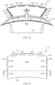
- FIGS. 3-7 Various embodiments of the inlet door are depicted in FIGS. 3-7 , and will now be described, beginning with the embodiment depicted in FIGS. 3 and 4 .
- the inlet door 140 includes an inner surface 302, an outer surface 304, and an outer peripheral edge 306 that is defined between the inner and outer surfaces 302, 304.
- the actuator 136 is coupled to the inner surface 302 of the inlet door 140. It will be appreciated, however, that in other embodiments the actuator 136 may be coupled to various other portions of the inlet door 140.
- a plurality of openings 308 extend through the inlet door 140 between the inner and outer surfaces 302, 304, and are disposed adjacent to the outer peripheral edge 306.
- the number, size, shape, spacing, and location of the openings 308 in the outer peripheral edge 306 of the inlet door 140 may vary.
- the outer peripheral edge 306 is defined by a front edge 312, a back edge 314, a first side edge 316, and a second side edge 318
- the openings 308 are disposed adjacent to only the front edge 312, the first side edge 316, and the second side edge 318.
- the openings 308 that are disposed adjacent to the front edge 312 are spaced evenly, the openings 308 disposed adjacent to the first side edge 316 are spaced evenly, and the openings 308 disposed adjacent to the second side edge 318 are spaced evenly.
- the depicted embodiment includes four evenly spaced openings 308 disposed adjacent to the front edge 312, and three openings disposed adjacent to each of the first and second side edges 316, 318, this is merely exemplary of one embodiment. In other embodiments, the number of openings may vary.
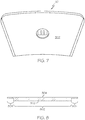
- the depicted openings 308 are shaped as rectangular slots, this shape is merely exemplary and may vary as needed or desired. For completeness, some non-limiting examples of alternative shapes are depicted in FIGS. 9-14
- the alternative embodiment depicted therein also includes openings 308 that are disposed adjacent to only the front edge 312, the first side edge 316, and the second side edge 318.
- the openings 308 disposed adjacent to the first side edge 316 are spaced evenly, and the openings 308 disposed adjacent to the second side edge 318 are spaced evenly.
- the openings 308 disposed adjacent to the front edge 312 are not evenly spaced.
- the inlet door 140 includes three openings 308 disposed adjacent to each of the first and second side edges 316, 318.
- the inlet door 104 includes only two openings 308, rather than four, disposed adjacent to the front edge 312. Again, this is merely exemplary of one alternative embodiment, and in other embodiments the number and shapes of the openings 308 may vary.
- the inlet door 140 includes openings 308 that are disposed adjacent to only the first and second side edges 316, 318, with no openings 308 disposed adjacent to the front or back edges 312, 314.
- the openings 308 disposed adjacent to the first and second side edges 316, 318 are spaced evenly.
- the inlet door 140 includes three openings 308 disposed adjacent to each of the first and second side edges 316, 318, this is merely exemplary of one alternative embodiment, and in other embodiments the number and shapes of the openings 308 may vary.
- the inlet door 140 also does not include any side members.
- conventionally known inlet doors 140 typically include a plurality of side members that extend from the inner surface 302 and into the air flow passage 134 when the inlet door 140 is in the closed position. The side members, when included, help to control airflow spillage around the inlet door 140 and minimize the loss of pressure in the airflow entering into the inlet port 126.
- the inlet door 140 is implemented without side members and also includes no openings 308.
- each of inlet doors 140 depicted in FIGS. 3-7 also include an insert portion 802 and a seal portion 804.
- the inlet portion 802 is configured to extend through the inlet port 126 and is disposed within the air flow passage 134 when the inlet door 140 is in the closed position.
- the seal portion 804 is disposed outward of the insert portion 802 and inward of the outer peripheral edge 306.
- the seal portion 804 sealingly engages the duct 114, and preventing the openings 308 from providing an open pathway to the inlet port 126 and air flow passage 134.
- Governmental agency requirements specifiy that the air flow passage 134 be completely sealed from the outside when the door 140 is closed. It will be appreciated that this is merely exemplary of one embodiment of an inlet door 140. Regardless, in each of the depicted embodiments, the openings 308 are disposed such that each extends through the seal portion 804.
- the embodiment depicted in FIG. 5 exhibits a reduction in door load of about 12% as compared to conventionally known doors; the embodiment depicted in FIG. 6 exhibits a reduction in door load of about 9% as compared to conventionally known doors; and the embodiment depicted in FIG. 7 exhibits a reduction in door load of about 6% as compared to conventionally known doors. It should be noted that reductions of this magnitude were wholly unexpected.
Description
- The present invention generally relates to auxiliary power units (APUs), and more particularly relates to an APU inlet door that has openings formed therein to provide improved performance.
- Auxiliary power units ("APU") are used in aircraft to provide electrical power and compressed air to various aircraft systems and components. When an aircraft is on the ground, its main source of electrical power and cabin conditioning comes from the APU. In particular, the APU can power the environmental control systems, air drive hydraulic pumps, and the starters for the engines. When an aircraft is in flight, the APU may provide pneumatic and/or electric power to the aircraft.
- Patent document number
US6264137B1 describes an air inlet assembly for bringing air to an auxiliary power unit mounted in the compartment of an aircraft. The assembly includes a duct extending from an intake contoured to conform to the to the aircraft fuselage to an exit coupled to the inlet plenum of the auxiliary power unit. A first door hingeably mounted to the aft side of said intake and moveable from an open position to a closed position where said first door lies flush against intake, said first door having a closing wall and two side walls and a second door hingeably mounted to the forward end of said intake, said second door having a plate with two inwardly extending walls, each of said inwardly extending walls hinged to one of said side walls so that the second door rotates with said first door. During ground operation air that would have swirled around the side walls of the first door thus generating inlet corner vortices are now blocked by the side walls of the second door. - Typically, APUs are located in the aft section of the aircraft, at or near the tailcone section and include inlet and exhaust ducting that exit through an opening, or cut-out, in the aircraft fuselage to allow sufficient air flow through to the APU. For aircraft on which APUs operate during flight, an inlet air door is typically provided to protect the APU from foreign object damage when not in use and/or during ground movement, and to maximize airflow into the APU when performance or oil cooling at altitude is required. Thus, when the APU is running, either on the ground or in flight, the inlet air door is in an open position.
- During in-flight operations of the APU, there is a low pressure wake formation on the backside of the open inlet door, which can create relatively high drag loads. These high drag loads may also induce undesirable amounts of vibration on the door, which can have deleterious structural impact and may reduce over inlet door lifetime.
- Hence, there is a need for an APU inlet door that, when open, does not exhibit undesirably high drag loads and/or does not have undesirable amounts of vibration induced therein and/or improves overall inlet door lifetime. The present invention addresses one or more of these needs.
- The present invention in its various aspects is as set out in the appended claims. In one embodiment, an inlet door system for providing air to at least an auxiliary power unit (APU) contained within an aircraft includes a duct, an inlet door, and a plurality of openings. The duct is configured to extend from the auxiliary power unit (APU) to an intake opening formed in an outer surface of the aircraft. The duct includes an inlet port, an outlet port, and a duct sidewall extending between the inlet port and the outlet port. The duct sidewall defines an air flow passage between the inlet port and the outlet port. The inlet door includes an inner surface, an outer surface, and an outer peripheral edge between the inner and outer surfaces. The door is rotationally coupled to the duct, and is configured to selectively rotate between a closed position, in which the door seals the air inlet port and prevents air flow into the inlet port, and a plurality of open positions, in which the door does not seal the air inlet and allows air flow into the inlet port. The openings extend through the inlet door between the inner surface and outer surface, and each opening is disposed adjacent to the outer peripheral edge.
- In another embodiment, an auxiliary power unit system includes an auxiliary power unit (APU), a duct, an inlet, and a plurality of openings. The APU includes at least an APU air inlet. The duct is coupled to and extends from the APU air inlet, and includes an inlet port, an outlet port, and a duct sidewall extending between the inlet port and the outlet port. The duct sidewall defines an air flow passage between the inlet port and the outlet port. The inlet door includes an inner surface, an outer surface, and an outer peripheral edge between the inner and outer surfaces. The door is rotationally coupled to the duct, and is configured to selectively rotate between a closed position, in which the door seals the air inlet port and prevents air flow into the inlet port, and a plurality of open positions, in which the door does not seal the air inlet and allows air flow into the inlet port. The openings extend through the inlet door between the inner surface and outer surface, and each opening is disposed adjacent to the outer peripheral edge.
- In yet another embodiment, an inlet door system for providing air to at least an auxiliary power unit (APU) contained within an aircraft includes a duct, an inlet door, an actuator, and a plurality of openings. The duct is configured to extend from the auxiliary power unit (APU) to an intake opening formed in an outer surface of the aircraft, and includes an inlet port, an outlet port, and a duct sidewall extending between the inlet port and the outlet port. The duct sidewall defines an air flow passage between the inlet port and the outlet port. The inlet door includes an inner surface, an outer surface, and an outer peripheral edge between the inner and outer surfaces. The outer peripheral edge is defined by a front edge, a back edge, a first side edge, and a second side edge. The door is rotationally coupled to the duct, and is configured to selectively rotate between a closed position, in which the door seals the air inlet port and prevents air flow into the inlet port, and a plurality of open positions, in which the door does not seal the air inlet and allows air flow into the inlet port. The actuator is coupled to the inlet door and is configured to selectively move the inlet door between the closed position and one or more of the open positions. The openings extend through the inlet door between the inner surface and outer surface. Each of the openings is disposed adjacent to only the front edge, the first side edge, and the second side edge.
- Furthermore, other desirable features and characteristics of the APU inlet door will become apparent from the subsequent detailed description and the appended claims, taken in conjunction with the accompanying drawings and the preceding background.
- The present invention will hereinafter be described in conjunction with the following drawing figures, wherein like numerals denote like elements, and wherein:
-
FIG. 1 depicts a cross-sectional schematic of a portion of an aircraft; -
FIG. 2 depicts a simplified cross section view of one embodiment of an auxiliary power unit; -
FIGS. 3-6 depict various embodiments of an inlet door that may be used in the aircraft ofFIG. 1 ; -
FIG. 7 depicts an embodiment which does not form part of the invention. -
FIG. 8 depicts a cross section view of the inlet door taken along line 8-8 inFIG. 4 ; and -
FIGS. 9-14 depict various examples of alternative shapes of openings that are formed in the inlet door. - The following detailed description is merely exemplary in nature and is not intended to limit the invention or the application and uses of the invention. As used herein, the word "exemplary" means "serving as an example, instance, or illustration." Thus, any embodiment described herein as "exemplary" is not necessarily to be construed as preferred or advantageous over other embodiments. All of the embodiments described herein are exemplary embodiments provided to enable persons skilled in the art to make or use the invention and not to limit the scope of the invention which is defined by the claims. Furthermore, there is no intention to be bound by any expressed or implied theory presented in the preceding technical field, background, brief summary, or the following detailed description.
- Turning now to
FIG. 1 , a cross-sectional schematic of a portion of anaircraft 100 is depicted. Theaircraft 100 includes an auxiliary power unit (APU)compartment 102 that is defined by anexterior surface 104 and afirewall 106. As is generally known, thefirewall 106 separates theAPU compartment 102 from other sections of theaircraft 100. In the depicted embodiment, the APUcompartment 102 is formed in the tailcone section of theaircraft 100. It will be appreciated, however, that this is merely exemplary, and that the APUcompartment 102 could be formed in any one of numerous other sections of theaircraft 100. It will additionally be appreciated that, depending on its location in theaircraft 100, the APUcompartment 102 may be defined by more than onefirewall 106. - No matter its specific location, the APU
compartment 102 includes one ormore intake openings 108, and an exhaust opening 112. As will be described in more detail further below, the one ormore intake openings 108 are configured to selectively receive a flow ofinlet air 109, and theexhaust opening 112 provides a point of egress from theAPU compartment 102 for APU exhaust and other gasses. Theinlet air 109 is selectively supplied to anAPU 110 that is mounted within thecompartment 102 and, in some embodiments, may also be supplied to thecompartment 102 for cooling purposes. Before proceeding further, and for completeness, a brief description of anexemplary APU 110 that may be mounted within thecompartment 102 will be provided. - With reference now to
FIG. 2 , an exemplary embodiment of theAPU 110 is depicted. Theexemplary APU 110 includes acompressor 202, a combustor 204, and aturbine 206. Air is directed into thecompressor 202 via anAPU air inlet 208. Thecompressor 202 raises the pressure of the air and supplies compressed air to both the combustor 204 and, in the depicted embodiment, to a bleedair outlet port 210. In the combustor 204, the compressed air is mixed with fuel that is supplied to the combustor 204 from a non-illustrated fuel source via a plurality offuel nozzles 212. The fuel/air mixture is combusted, generating high-energy gas, which is then directed into theturbine 206. - The high-energy gas expands through the
turbine 206, where it gives up much of its energy and causes theturbine 206 to rotate. The gas is then exhausted from theAPU 110 via an exhaustgas outlet nozzle 214. As theturbine 206 rotates, it drives, via aturbine shaft 216, various types of equipment that may be mounted in, or coupled to, theAPU 110. For example, in the depicted embodiment theturbine 206 drives thecompressor 202. It will be appreciated that theturbine 206 may also be used to drive a generator and/or a load compressor and/or other rotational equipment, which are not shown inFIG. 2 for ease of illustration. - Returning once again to
FIG. 1 , it is seen that theAPU 110, and more specifically theAPU air inlet 208, is coupled to aduct 114. It is additionally seen that theAPU 110, and more specifically the exhaustgas outlet nozzle 214, is coupled to anexhaust system 115. As will be described in more detail below, theduct 114 is coupled to selectively receive theinlet air 109. Theexhaust system 115, at least in the depicted embodiment, includes aneductor 116 and anoutlet duct 118. Theeductor 116 may be variously configured, but in the depicted embodiment it preferably surrounds, and receives the gas that is exhausted from, the exhaustgas outlet nozzle 214. It will be appreciated that in other embodiments, the exhaustgas outlet nozzle 214 may communicate with theeductor 116 via one or more intermediate components such as, for example, a mixer. Nonetheless, theeductor 116 is additionally configured, upon receipt of the exhaust gas, to draw compartment cooling air that, in some embodiments, is selectively supplied to theAPU compartment 102 from acompartment cooling duct 122 through, for example, an oil cooler 124 that is coupled to theeductor 116, and into theexhaust duct 118, which is coupled to, and in fluid communication with, theexhaust opening 112. - As was mentioned above, the
duct 114 is coupled to selectively receive theinlet air 109. To do so, theduct 114 is coupled to and extends from theAPU air inlet 208, and includes aninlet port 126, anoutlet port 128, and aduct sidewall 132. Theinlet port 126 is coupled to selectively receive theinlet air flow 109, and theoutlet port 128 is coupled to theAPU air inlet 208. Theduct sidewall 132 extends between theinlet port 126 and theoutlet port 128, and defines anair flow passage 134 between theinlet port 126 and theoutlet port 128. - As
FIG. 1 also depicts, aninlet door 140 is provided and is used to selectively allow theinlet air 109 to ingress into theduct 114. Theinlet door 140 is rotationally coupled to the duct 114 (or other static structure) and is configured to selectively rotate between a closed position and a plurality of open positions. In the closed position, thedoor 140 seals, and thus prevents air flow into, theinlet port 126. In any one of the open positions, thedoor 140 does not seal theair inlet 126 and thus allows theinlet air 109 to flow into theinlet port 126. Theinlet door 140 is rotated via anactuator 136. Theactuator 136 is coupled to theinlet door 140 and is configured to selectively rotate theinlet door 140 between the closed position and an open position. Theactuator 136 may be implemented using any one of numerous types of pneumatic, hydraulic, or electric actuators. Theactuator 136 may also be located at various locations relative to theinlet duct 114. For example, it may be located in front of theinlet duct 114 or behind theinlet duct 114, just to name two alternate locations. Various embodiments of the inlet door are depicted inFIGS. 3-7 , and will now be described, beginning with the embodiment depicted inFIGS. 3 and 4 . - The
inlet door 140 includes aninner surface 302, anouter surface 304, and an outerperipheral edge 306 that is defined between the inner andouter surfaces actuator 136 is coupled to theinner surface 302 of theinlet door 140. It will be appreciated, however, that in other embodiments theactuator 136 may be coupled to various other portions of theinlet door 140. AsFIGS. 3 and 4 also depict, a plurality ofopenings 308 extend through theinlet door 140 between the inner andouter surfaces peripheral edge 306. - It will be appreciated that the number, size, shape, spacing, and location of the
openings 308 in the outerperipheral edge 306 of theinlet door 140 may vary. In the depicted embodiment, in which the outerperipheral edge 306 is defined by afront edge 312, aback edge 314, afirst side edge 316, and asecond side edge 318, theopenings 308 are disposed adjacent to only thefront edge 312, thefirst side edge 316, and thesecond side edge 318. It is additionally seen, at least in the depicted embodiment, that theopenings 308 that are disposed adjacent to thefront edge 312 are spaced evenly, theopenings 308 disposed adjacent to thefirst side edge 316 are spaced evenly, and theopenings 308 disposed adjacent to thesecond side edge 318 are spaced evenly. Although the depicted embodiment includes four evenly spacedopenings 308 disposed adjacent to thefront edge 312, and three openings disposed adjacent to each of the first and second side edges 316, 318, this is merely exemplary of one embodiment. In other embodiments, the number of openings may vary. Moreover, although the depictedopenings 308 are shaped as rectangular slots, this shape is merely exemplary and may vary as needed or desired. For completeness, some non-limiting examples of alternative shapes are depicted inFIGS. 9-14 - Referring now to
FIG. 5 , the alternative embodiment depicted therein also includesopenings 308 that are disposed adjacent to only thefront edge 312, thefirst side edge 316, and thesecond side edge 318. However, in this embodiment, theopenings 308 disposed adjacent to thefirst side edge 316 are spaced evenly, and theopenings 308 disposed adjacent to thesecond side edge 318 are spaced evenly. Conversely, theopenings 308 disposed adjacent to thefront edge 312 are not evenly spaced. Similar to the embodiment depicted inFIGS. 3 and 4 , theinlet door 140 includes threeopenings 308 disposed adjacent to each of the first and second side edges 316, 318. Unlike that embodiment, theinlet door 104 includes only twoopenings 308, rather than four, disposed adjacent to thefront edge 312. Again, this is merely exemplary of one alternative embodiment, and in other embodiments the number and shapes of theopenings 308 may vary. - In yet another alternative embodiment, which is depicted in
FIG. 6 , theinlet door 140 includesopenings 308 that are disposed adjacent to only the first and second side edges 316, 318, with noopenings 308 disposed adjacent to the front or back edges 312, 314. Theopenings 308 disposed adjacent to the first and second side edges 316, 318 are spaced evenly. Again, although theinlet door 140 includes threeopenings 308 disposed adjacent to each of the first and second side edges 316, 318, this is merely exemplary of one alternative embodiment, and in other embodiments the number and shapes of theopenings 308 may vary. - Regardless of the number, size, shape, spacing, and location of the
openings 308, in each of the depicted embodiments theinlet door 140 also does not include any side members. In particular, conventionally knowninlet doors 140 typically include a plurality of side members that extend from theinner surface 302 and into theair flow passage 134 when theinlet door 140 is in the closed position. The side members, when included, help to control airflow spillage around theinlet door 140 and minimize the loss of pressure in the airflow entering into theinlet port 126. In one other embodiment, which is depicted inFIG. 7 , theinlet door 140 is implemented without side members and also includes noopenings 308. - With reference now to
FIG. 8 , it should be noted that each ofinlet doors 140 depicted inFIGS. 3-7 also include aninsert portion 802 and aseal portion 804. Theinlet portion 802 is configured to extend through theinlet port 126 and is disposed within theair flow passage 134 when theinlet door 140 is in the closed position. Theseal portion 804 is disposed outward of theinsert portion 802 and inward of the outerperipheral edge 306. When theinlet door 140 is in the closed position, theseal portion 804 sealingly engages theduct 114, and preventing theopenings 308 from providing an open pathway to theinlet port 126 andair flow passage 134. Governmental agency requirements specifiy that theair flow passage 134 be completely sealed from the outside when thedoor 140 is closed. It will be appreciated that this is merely exemplary of one embodiment of aninlet door 140. Regardless, in each of the depicted embodiments, theopenings 308 are disposed such that each extends through theseal portion 804. - The
inlet door 140 embodiments disclosed herein that include theopenings 308, and that are implemented without side members, exhibit significant reductions in door loads, while not significantly impacting the flow ofinlet air 109 into theduct 114. Indeed, with the embodiment depicted inFIGS. 3 and 4 , theinlet door 140 exhibits a reduction in door load of about 13% as compared to conventionally known doors. The embodiment depicted inFIG. 5 exhibits a reduction in door load of about 12% as compared to conventionally known doors; the embodiment depicted inFIG. 6 exhibits a reduction in door load of about 9% as compared to conventionally known doors; and the embodiment depicted inFIG. 7 exhibits a reduction in door load of about 6% as compared to conventionally known doors. It should be noted that reductions of this magnitude were wholly unexpected. - In this document, relational terms such as first and second, and the like may be used solely to distinguish one entity or action from another entity or action without necessarily requiring or implying any actual such relationship or order between such entities or actions. Numerical ordinals such as "first," "second," "third," etc. simply denote different singles of a plurality and do not imply any order or sequence unless specifically defined by the claim language. The sequence of the text in any of the claims does not imply that process steps must be performed in a temporal or logical order according to such sequence unless it is specifically defined by the language of the claim. The process steps may be interchanged in any order without departing from the scope of the invention as long as such an interchange does not contradict the claim language and is not logically nonsensical.
- Furthermore, depending on the context, words such as "connect" or "coupled to" used in describing a relationship between different elements do not imply that a direct physical connection must be made between these elements. For example, two elements may be connected to each other physically, electronically, logically, or in any other manner, through one or more additional elements.
- While at least one exemplary embodiment has been presented in the foregoing detailed description of the invention, it should be appreciated that a vast number of variations exist. It should also be appreciated that the exemplary embodiment or exemplary embodiments are only examples, and are not intended to limit the scope, applicability, or configuration of the invention in any way. Rather, the foregoing detailed description will provide those skilled in the art with a convenient road map for implementing an exemplary embodiment of the invention. It being understood that various changes may be made in the function and arrangement of elements described in an exemplary embodiment without departing from the scope of the invention as set forth in the appended claims.
Claims (9)
- An inlet door system for providing air to at least an auxiliary power unit (APU) contained within an aircraft(100), the inlet door system comprising:a duct(114) configured to extend from the auxiliary power unit (APU) to an intake opening (108)formed in an outer surface(304) of the aircraft(100), the duct(114) including an inlet port(126), an outlet port(128), and a duct sidewall(132) extending between the inlet port (126)and the outlet port(128), the duct sidewall(132) defining an air flow passage(134) between the inlet port(126) and the outlet port(128);an inlet door(140) including an inner surface(302), an outer surface(304), and an outer peripheral edge(306) between the inner and outer surfaces(302,304), the door rotationally coupled to the duct(114), the door configured to selectively rotate between (i) a closed position, in which the door seals the air inlet port(126) and prevents air flow into the inlet port(126), and (ii) a plurality of open positions, in which the door does not seal the air inlet and allows air flow into the inlet port(126); characterised in thata plurality of openings(308) extending through the inlet door(140) between the inner surface (302)and outer surface(304), each opening(308) disposed adjacent to the outer peripheral edge(306).
- The system of claim 1, wherein:the outer peripheral edge(306) of the inlet door(140) is defined by a front edge(312), a back edge (314), a first side edge(316), and a second side edge(318); andthe openings(308) are disposed adjacent to only the first side edge(316) and the second side edge(318).
- The system of claim 2, wherein:the openings(308) disposed adjacent to the first side edge (316)are spaced evenly, and the openings(308) disposed adjacent to the second side edge(318) are spaced evenly.
- The system of claim 1, wherein:the outer peripheral edge(306) of the inlet door(140) is defined by a front edge(312), a back edge(314), a first side edge(316), and a second side edge(318); andthe openings(308) are disposed adjacent to only the front edge(312), the first side edge(316), and the second side edge(318).
- The system of claim 4, wherein:the openings(308) disposed adjacent to the front edge(312) are spaced evenly, the openings(308) disposed adjacent to the first side edge(316)are spaced evenly, and the openings(308) disposed adjacent to the second side edge(318) are spaced evenly.
- The system of claim 1, wherein the inlet door (140) comprises:an insert portion that extends through the inlet port(126) and is disposed within the air flow passage(134) when the inlet door(140) is in the closed position; anda seal portion disposed outward of the insert portion and inward of the outer peripheral edge(306), the seal portion engaging the inlet duct(114) when the inlet door(140) is in the closed position.
- The system of claim 6, wherein the openings(308) extend through the seal portion.
- The system of claim 1, wherein the inlet door (140) does not include any side members that extend into the air flow passage(134) when the inlet door(140) is in the closed position.
- The system of claim 1, further comprising:an actuator coupled to the inlet door(140) and configured to selectively move the inlet door (140) between the closed position and one or more of the open positions.
Applications Claiming Priority (1)
| Application Number | Priority Date | Filing Date | Title |
|---|---|---|---|
| US14/063,324 US9145214B2 (en) | 2013-10-25 | 2013-10-25 | Auxiliary power unit inlet door having openings formed therein |
Publications (2)
| Publication Number | Publication Date |
|---|---|
| EP2865599A1 EP2865599A1 (en) | 2015-04-29 |
| EP2865599B1 true EP2865599B1 (en) | 2017-03-29 |
Family
ID=51661877
Family Applications (1)
| Application Number | Title | Priority Date | Filing Date |
|---|---|---|---|
| EP14186490.0A Active EP2865599B1 (en) | 2013-10-25 | 2014-09-25 | Auxiliary power unit inlet door having openings formed therein |
Country Status (2)
| Country | Link |
|---|---|
| US (1) | US9145214B2 (en) |
| EP (1) | EP2865599B1 (en) |
Families Citing this family (9)
| Publication number | Priority date | Publication date | Assignee | Title |
|---|---|---|---|---|
| CN105201653B (en) * | 2015-09-10 | 2017-03-29 | 中国商用飞机有限责任公司 | The actuation mechanism of the inlet flap of auxiliary power unit gas handling system |
| WO2018067310A1 (en) | 2016-10-05 | 2018-04-12 | Safran Power Unit | Translatable scoop for auxiliary power units air intake |
| US20180257788A1 (en) * | 2017-03-09 | 2018-09-13 | United Technologies Corporation | Air intake assembly with horizontal door for an aircraft auxiliary power unit |
| US10435166B2 (en) * | 2017-05-17 | 2019-10-08 | Bell Helicopter Textron Inc. | Cowling with structural hand holds operating also as maintenance position bumpers |
| ES2890374T3 (en) * | 2017-10-30 | 2022-01-18 | Airbus Operations Sl | Aircraft tail cone incorporating an APU with annular air intake |
| EP3587273B1 (en) * | 2018-06-22 | 2023-10-11 | Airbus Operations, S.L.U. | Air intake system |
| US11085372B2 (en) * | 2018-07-18 | 2021-08-10 | The Boeing Company | Anti-ice system exhaust air disruptor |
| KR102587329B1 (en) * | 2018-12-10 | 2023-10-10 | 한화에어로스페이스 주식회사 | An auxiliary power unit for reducing the flow loss of the gas |
| DE102021113818B4 (en) | 2021-05-28 | 2023-06-15 | Elektro-Metall Export Gesellschaft mit beschränkter Haftung | Airplane, especially passenger plane |
Family Cites Families (13)
| Publication number | Priority date | Publication date | Assignee | Title |
|---|---|---|---|---|
| US5263502A (en) * | 1992-07-06 | 1993-11-23 | Jack Dick | Inlet valve assembly |
| US6138950A (en) * | 1998-10-06 | 2000-10-31 | Northrop Grumman Corporation | Aircraft engine air intake system |
| US6213426B1 (en) | 1999-07-09 | 2001-04-10 | The Boeing Company | Monolithic structure with redundant load paths |
| US6264137B1 (en) | 2000-02-25 | 2001-07-24 | Honeywell International Inc. | Inlet vortex bustor and ice protector for auxiliary power units |
| US20040189047A1 (en) | 2003-03-26 | 2004-09-30 | Barry Brian S. | Reduced aerodynamic drag truck gate |
| US7600713B2 (en) * | 2005-03-04 | 2009-10-13 | Honeywell International Inc. | Pre-hung inlet door system |
| US7469545B2 (en) | 2005-09-27 | 2008-12-30 | Honeywell International Inc. | Auxiliary power unit inlet door position control system and method |
| US7540142B2 (en) * | 2006-02-21 | 2009-06-02 | Honeywell International Inc. | Multiple auxiliary power unit system inlet ducts controlled by a single actuator |
| US8439295B2 (en) * | 2006-07-14 | 2013-05-14 | Aerospace Filtration Systems, Inc. | Aircraft engine inlet pivotable barrier filter |
| US8141816B2 (en) * | 2008-04-30 | 2012-03-27 | Honeywell International Inc. | AFT inlet duct mounted door actuator |
| US8113767B2 (en) | 2008-09-15 | 2012-02-14 | Hamilton Sundstrand Corporation | Auxiliary power unit inlet duct with acoustic silencing |
| CN102777261B (en) * | 2011-05-13 | 2016-02-10 | 中国商用飞机有限责任公司 | Inlet flap substrate and comprise the inlet flap of this substrate |
| ES2401015B1 (en) * | 2011-09-29 | 2014-03-13 | Airbus Operations, S.L. | AIR INTAKE WITH DOUBLE DOOR |
-
2013
- 2013-10-25 US US14/063,324 patent/US9145214B2/en active Active
-
2014
- 2014-09-25 EP EP14186490.0A patent/EP2865599B1/en active Active
Non-Patent Citations (1)
| Title |
|---|
| None * |
Also Published As
| Publication number | Publication date |
|---|---|
| US20150115099A1 (en) | 2015-04-30 |
| EP2865599A1 (en) | 2015-04-29 |
| US9145214B2 (en) | 2015-09-29 |
Similar Documents
| Publication | Publication Date | Title |
|---|---|---|
| EP2865599B1 (en) | Auxiliary power unit inlet door having openings formed therein | |
| US7600714B2 (en) | Diffusing air inlet door assembly | |
| US7540142B2 (en) | Multiple auxiliary power unit system inlet ducts controlled by a single actuator | |
| CA2401649C (en) | Inlet vortex bustor and ice protector for auxiliary power units | |
| RU2494009C2 (en) | Aircraft fresh air intake | |
| US9045998B2 (en) | System for directing air flow to a plurality of plena | |
| CA2783036C (en) | Pressure influencing assembly for an aircraft auxiliary system | |
| EP2987985B1 (en) | Actively controlled cooling air exhaust door on aircraft engine nacelle | |
| US10829232B2 (en) | Aircraft comprising a propulsion assembly including a fan on the rear of the fuselage | |
| US10569893B2 (en) | Auxiliary power unit inlet apparatus and methods | |
| EP3055220B1 (en) | Acoustic controlled ice deflecting auxiliary power unit inlet system | |
| US20160017844A1 (en) | Reverse core engine with thrust reverser | |
| EP2860113B1 (en) | Engine mounted inlet plenum for a rotorcraft | |
| EP3597927B1 (en) | Bleed valve with resonance chamber integrated in the closing member | |
| EP2272758B1 (en) | Ram door assemblies | |
| EP2610179A2 (en) | Aircraft air inlet diverter assemblies with improved aerodynamic characteristics | |
| US8016227B2 (en) | Non-handed engine cowl doors for fuselage mounted turbine engines | |
| US20200332742A1 (en) | Aircraft engine assembly | |
| US20100193643A1 (en) | Lift fan system | |
| CN114893342A (en) | Air inlet type vertical axis ram air turbine emergency energy system |
Legal Events
| Date | Code | Title | Description |
|---|---|---|---|
| PUAI | Public reference made under article 153(3) epc to a published international application that has entered the european phase |
Free format text: ORIGINAL CODE: 0009012 |
|
| 17P | Request for examination filed |
Effective date: 20140925 |
|
| AK | Designated contracting states |
Kind code of ref document: A1 Designated state(s): AL AT BE BG CH CY CZ DE DK EE ES FI FR GB GR HR HU IE IS IT LI LT LU LV MC MK MT NL NO PL PT RO RS SE SI SK SM TR |
|
| AX | Request for extension of the european patent |
Extension state: BA ME |
|
| RAP1 | Party data changed (applicant data changed or rights of an application transferred) |
Owner name: HONEYWELL INTERNATIONAL INC. |
|
| GRAP | Despatch of communication of intention to grant a patent |
Free format text: ORIGINAL CODE: EPIDOSNIGR1 |
|
| INTG | Intention to grant announced |
Effective date: 20161118 |
|
| GRAS | Grant fee paid |
Free format text: ORIGINAL CODE: EPIDOSNIGR3 |
|
| GRAA | (expected) grant |
Free format text: ORIGINAL CODE: 0009210 |
|
| AK | Designated contracting states |
Kind code of ref document: B1 Designated state(s): AL AT BE BG CH CY CZ DE DK EE ES FI FR GB GR HR HU IE IS IT LI LT LU LV MC MK MT NL NO PL PT RO RS SE SI SK SM TR |
|
| REG | Reference to a national code |
Ref country code: GB Ref legal event code: FG4D |
|
| REG | Reference to a national code |
Ref country code: CH Ref legal event code: EP |
|
| REG | Reference to a national code |
Ref country code: AT Ref legal event code: REF Ref document number: 879502 Country of ref document: AT Kind code of ref document: T Effective date: 20170415 |
|
| REG | Reference to a national code |
Ref country code: IE Ref legal event code: FG4D |
|
| REG | Reference to a national code |
Ref country code: DE Ref legal event code: R096 Ref document number: 602014008025 Country of ref document: DE |
|
| PG25 | Lapsed in a contracting state [announced via postgrant information from national office to epo] |
Ref country code: LT Free format text: LAPSE BECAUSE OF FAILURE TO SUBMIT A TRANSLATION OF THE DESCRIPTION OR TO PAY THE FEE WITHIN THE PRESCRIBED TIME-LIMIT Effective date: 20170329 Ref country code: HR Free format text: LAPSE BECAUSE OF FAILURE TO SUBMIT A TRANSLATION OF THE DESCRIPTION OR TO PAY THE FEE WITHIN THE PRESCRIBED TIME-LIMIT Effective date: 20170329 Ref country code: NO Free format text: LAPSE BECAUSE OF FAILURE TO SUBMIT A TRANSLATION OF THE DESCRIPTION OR TO PAY THE FEE WITHIN THE PRESCRIBED TIME-LIMIT Effective date: 20170629 Ref country code: GR Free format text: LAPSE BECAUSE OF FAILURE TO SUBMIT A TRANSLATION OF THE DESCRIPTION OR TO PAY THE FEE WITHIN THE PRESCRIBED TIME-LIMIT Effective date: 20170630 Ref country code: FI Free format text: LAPSE BECAUSE OF FAILURE TO SUBMIT A TRANSLATION OF THE DESCRIPTION OR TO PAY THE FEE WITHIN THE PRESCRIBED TIME-LIMIT Effective date: 20170329 |
|
| REG | Reference to a national code |
Ref country code: NL Ref legal event code: MP Effective date: 20170329 |
|
| REG | Reference to a national code |
Ref country code: AT Ref legal event code: MK05 Ref document number: 879502 Country of ref document: AT Kind code of ref document: T Effective date: 20170329 |
|
| PG25 | Lapsed in a contracting state [announced via postgrant information from national office to epo] |
Ref country code: RS Free format text: LAPSE BECAUSE OF FAILURE TO SUBMIT A TRANSLATION OF THE DESCRIPTION OR TO PAY THE FEE WITHIN THE PRESCRIBED TIME-LIMIT Effective date: 20170329 Ref country code: BG Free format text: LAPSE BECAUSE OF FAILURE TO SUBMIT A TRANSLATION OF THE DESCRIPTION OR TO PAY THE FEE WITHIN THE PRESCRIBED TIME-LIMIT Effective date: 20170629 Ref country code: SE Free format text: LAPSE BECAUSE OF FAILURE TO SUBMIT A TRANSLATION OF THE DESCRIPTION OR TO PAY THE FEE WITHIN THE PRESCRIBED TIME-LIMIT Effective date: 20170329 Ref country code: LV Free format text: LAPSE BECAUSE OF FAILURE TO SUBMIT A TRANSLATION OF THE DESCRIPTION OR TO PAY THE FEE WITHIN THE PRESCRIBED TIME-LIMIT Effective date: 20170329 |
|
| PG25 | Lapsed in a contracting state [announced via postgrant information from national office to epo] |
Ref country code: NL Free format text: LAPSE BECAUSE OF FAILURE TO SUBMIT A TRANSLATION OF THE DESCRIPTION OR TO PAY THE FEE WITHIN THE PRESCRIBED TIME-LIMIT Effective date: 20170329 |
|
| PG25 | Lapsed in a contracting state [announced via postgrant information from national office to epo] |
Ref country code: CZ Free format text: LAPSE BECAUSE OF FAILURE TO SUBMIT A TRANSLATION OF THE DESCRIPTION OR TO PAY THE FEE WITHIN THE PRESCRIBED TIME-LIMIT Effective date: 20170329 Ref country code: RO Free format text: LAPSE BECAUSE OF FAILURE TO SUBMIT A TRANSLATION OF THE DESCRIPTION OR TO PAY THE FEE WITHIN THE PRESCRIBED TIME-LIMIT Effective date: 20170329 Ref country code: AT Free format text: LAPSE BECAUSE OF FAILURE TO SUBMIT A TRANSLATION OF THE DESCRIPTION OR TO PAY THE FEE WITHIN THE PRESCRIBED TIME-LIMIT Effective date: 20170329 Ref country code: EE Free format text: LAPSE BECAUSE OF FAILURE TO SUBMIT A TRANSLATION OF THE DESCRIPTION OR TO PAY THE FEE WITHIN THE PRESCRIBED TIME-LIMIT Effective date: 20170329 Ref country code: IT Free format text: LAPSE BECAUSE OF FAILURE TO SUBMIT A TRANSLATION OF THE DESCRIPTION OR TO PAY THE FEE WITHIN THE PRESCRIBED TIME-LIMIT Effective date: 20170329 Ref country code: SK Free format text: LAPSE BECAUSE OF FAILURE TO SUBMIT A TRANSLATION OF THE DESCRIPTION OR TO PAY THE FEE WITHIN THE PRESCRIBED TIME-LIMIT Effective date: 20170329 Ref country code: ES Free format text: LAPSE BECAUSE OF FAILURE TO SUBMIT A TRANSLATION OF THE DESCRIPTION OR TO PAY THE FEE WITHIN THE PRESCRIBED TIME-LIMIT Effective date: 20170329 |
|
| PG25 | Lapsed in a contracting state [announced via postgrant information from national office to epo] |
Ref country code: PL Free format text: LAPSE BECAUSE OF FAILURE TO SUBMIT A TRANSLATION OF THE DESCRIPTION OR TO PAY THE FEE WITHIN THE PRESCRIBED TIME-LIMIT Effective date: 20170329 Ref country code: IS Free format text: LAPSE BECAUSE OF FAILURE TO SUBMIT A TRANSLATION OF THE DESCRIPTION OR TO PAY THE FEE WITHIN THE PRESCRIBED TIME-LIMIT Effective date: 20170729 Ref country code: SM Free format text: LAPSE BECAUSE OF FAILURE TO SUBMIT A TRANSLATION OF THE DESCRIPTION OR TO PAY THE FEE WITHIN THE PRESCRIBED TIME-LIMIT Effective date: 20170329 Ref country code: PT Free format text: LAPSE BECAUSE OF FAILURE TO SUBMIT A TRANSLATION OF THE DESCRIPTION OR TO PAY THE FEE WITHIN THE PRESCRIBED TIME-LIMIT Effective date: 20170731 |
|
| REG | Reference to a national code |
Ref country code: DE Ref legal event code: R097 Ref document number: 602014008025 Country of ref document: DE |
|
| PG25 | Lapsed in a contracting state [announced via postgrant information from national office to epo] |
Ref country code: DK Free format text: LAPSE BECAUSE OF FAILURE TO SUBMIT A TRANSLATION OF THE DESCRIPTION OR TO PAY THE FEE WITHIN THE PRESCRIBED TIME-LIMIT Effective date: 20170329 |
|
| PLBE | No opposition filed within time limit |
Free format text: ORIGINAL CODE: 0009261 |
|
| STAA | Information on the status of an ep patent application or granted ep patent |
Free format text: STATUS: NO OPPOSITION FILED WITHIN TIME LIMIT |
|
| 26N | No opposition filed |
Effective date: 20180103 |
|
| REG | Reference to a national code |
Ref country code: CH Ref legal event code: PL |
|
| PG25 | Lapsed in a contracting state [announced via postgrant information from national office to epo] |
Ref country code: MC Free format text: LAPSE BECAUSE OF FAILURE TO SUBMIT A TRANSLATION OF THE DESCRIPTION OR TO PAY THE FEE WITHIN THE PRESCRIBED TIME-LIMIT Effective date: 20170329 Ref country code: SI Free format text: LAPSE BECAUSE OF FAILURE TO SUBMIT A TRANSLATION OF THE DESCRIPTION OR TO PAY THE FEE WITHIN THE PRESCRIBED TIME-LIMIT Effective date: 20170329 |
|
| REG | Reference to a national code |
Ref country code: IE Ref legal event code: MM4A |
|
| REG | Reference to a national code |
Ref country code: BE Ref legal event code: MM Effective date: 20170930 |
|
| PG25 | Lapsed in a contracting state [announced via postgrant information from national office to epo] |
Ref country code: LU Free format text: LAPSE BECAUSE OF NON-PAYMENT OF DUE FEES Effective date: 20170925 |
|
| REG | Reference to a national code |
Ref country code: FR Ref legal event code: ST Effective date: 20180531 |
|
| PG25 | Lapsed in a contracting state [announced via postgrant information from national office to epo] |
Ref country code: CH Free format text: LAPSE BECAUSE OF NON-PAYMENT OF DUE FEES Effective date: 20170930 Ref country code: IE Free format text: LAPSE BECAUSE OF NON-PAYMENT OF DUE FEES Effective date: 20170925 Ref country code: LI Free format text: LAPSE BECAUSE OF NON-PAYMENT OF DUE FEES Effective date: 20170930 |
|
| PG25 | Lapsed in a contracting state [announced via postgrant information from national office to epo] |
Ref country code: FR Free format text: LAPSE BECAUSE OF NON-PAYMENT OF DUE FEES Effective date: 20171002 Ref country code: BE Free format text: LAPSE BECAUSE OF NON-PAYMENT OF DUE FEES Effective date: 20170930 |
|
| PG25 | Lapsed in a contracting state [announced via postgrant information from national office to epo] |
Ref country code: MT Free format text: LAPSE BECAUSE OF NON-PAYMENT OF DUE FEES Effective date: 20170925 |
|
| GBPC | Gb: european patent ceased through non-payment of renewal fee |
Effective date: 20180925 |
|
| PG25 | Lapsed in a contracting state [announced via postgrant information from national office to epo] |
Ref country code: HU Free format text: LAPSE BECAUSE OF FAILURE TO SUBMIT A TRANSLATION OF THE DESCRIPTION OR TO PAY THE FEE WITHIN THE PRESCRIBED TIME-LIMIT; INVALID AB INITIO Effective date: 20140925 |
|
| PG25 | Lapsed in a contracting state [announced via postgrant information from national office to epo] |
Ref country code: GB Free format text: LAPSE BECAUSE OF NON-PAYMENT OF DUE FEES Effective date: 20180925 Ref country code: CY Free format text: LAPSE BECAUSE OF FAILURE TO SUBMIT A TRANSLATION OF THE DESCRIPTION OR TO PAY THE FEE WITHIN THE PRESCRIBED TIME-LIMIT Effective date: 20170329 |
|
| PG25 | Lapsed in a contracting state [announced via postgrant information from national office to epo] |
Ref country code: MK Free format text: LAPSE BECAUSE OF FAILURE TO SUBMIT A TRANSLATION OF THE DESCRIPTION OR TO PAY THE FEE WITHIN THE PRESCRIBED TIME-LIMIT Effective date: 20170329 |
|
| PG25 | Lapsed in a contracting state [announced via postgrant information from national office to epo] |
Ref country code: TR Free format text: LAPSE BECAUSE OF FAILURE TO SUBMIT A TRANSLATION OF THE DESCRIPTION OR TO PAY THE FEE WITHIN THE PRESCRIBED TIME-LIMIT Effective date: 20170329 |
|
| PG25 | Lapsed in a contracting state [announced via postgrant information from national office to epo] |
Ref country code: AL Free format text: LAPSE BECAUSE OF FAILURE TO SUBMIT A TRANSLATION OF THE DESCRIPTION OR TO PAY THE FEE WITHIN THE PRESCRIBED TIME-LIMIT Effective date: 20170329 |
|
| PGFP | Annual fee paid to national office [announced via postgrant information from national office to epo] |
Ref country code: DE Payment date: 20220927 Year of fee payment: 9 |
|
| P01 | Opt-out of the competence of the unified patent court (upc) registered |
Effective date: 20230525 |