EP2865356A1 - Hybrid prosthetic hand - Google Patents
Hybrid prosthetic hand Download PDFInfo
- Publication number
- EP2865356A1 EP2865356A1 EP20140190163 EP14190163A EP2865356A1 EP 2865356 A1 EP2865356 A1 EP 2865356A1 EP 20140190163 EP20140190163 EP 20140190163 EP 14190163 A EP14190163 A EP 14190163A EP 2865356 A1 EP2865356 A1 EP 2865356A1
- Authority
- EP
- European Patent Office
- Prior art keywords
- amputee
- motion
- mechanical
- stage
- prosthetic hand
- Prior art date
- Legal status (The legal status is an assumption and is not a legal conclusion. Google has not performed a legal analysis and makes no representation as to the accuracy of the status listed.)
- Withdrawn
Links
Images

Classifications
-
- A—HUMAN NECESSITIES
- A61—MEDICAL OR VETERINARY SCIENCE; HYGIENE
- A61F—FILTERS IMPLANTABLE INTO BLOOD VESSELS; PROSTHESES; DEVICES PROVIDING PATENCY TO, OR PREVENTING COLLAPSING OF, TUBULAR STRUCTURES OF THE BODY, e.g. STENTS; ORTHOPAEDIC, NURSING OR CONTRACEPTIVE DEVICES; FOMENTATION; TREATMENT OR PROTECTION OF EYES OR EARS; BANDAGES, DRESSINGS OR ABSORBENT PADS; FIRST-AID KITS
- A61F2/00—Filters implantable into blood vessels; Prostheses, i.e. artificial substitutes or replacements for parts of the body; Appliances for connecting them with the body; Devices providing patency to, or preventing collapsing of, tubular structures of the body, e.g. stents
- A61F2/50—Prostheses not implantable in the body
- A61F2/68—Operating or control means
- A61F2/70—Operating or control means electrical
- A61F2/72—Bioelectric control, e.g. myoelectric
-
- A—HUMAN NECESSITIES
- A61—MEDICAL OR VETERINARY SCIENCE; HYGIENE
- A61F—FILTERS IMPLANTABLE INTO BLOOD VESSELS; PROSTHESES; DEVICES PROVIDING PATENCY TO, OR PREVENTING COLLAPSING OF, TUBULAR STRUCTURES OF THE BODY, e.g. STENTS; ORTHOPAEDIC, NURSING OR CONTRACEPTIVE DEVICES; FOMENTATION; TREATMENT OR PROTECTION OF EYES OR EARS; BANDAGES, DRESSINGS OR ABSORBENT PADS; FIRST-AID KITS
- A61F2/00—Filters implantable into blood vessels; Prostheses, i.e. artificial substitutes or replacements for parts of the body; Appliances for connecting them with the body; Devices providing patency to, or preventing collapsing of, tubular structures of the body, e.g. stents
- A61F2/50—Prostheses not implantable in the body
- A61F2/54—Artificial arms or hands or parts thereof
- A61F2/58—Elbows; Wrists ; Other joints; Hands
- A61F2/583—Hands; Wrist joints
- A61F2/586—Fingers
-
- A—HUMAN NECESSITIES
- A61—MEDICAL OR VETERINARY SCIENCE; HYGIENE
- A61F—FILTERS IMPLANTABLE INTO BLOOD VESSELS; PROSTHESES; DEVICES PROVIDING PATENCY TO, OR PREVENTING COLLAPSING OF, TUBULAR STRUCTURES OF THE BODY, e.g. STENTS; ORTHOPAEDIC, NURSING OR CONTRACEPTIVE DEVICES; FOMENTATION; TREATMENT OR PROTECTION OF EYES OR EARS; BANDAGES, DRESSINGS OR ABSORBENT PADS; FIRST-AID KITS
- A61F2/00—Filters implantable into blood vessels; Prostheses, i.e. artificial substitutes or replacements for parts of the body; Appliances for connecting them with the body; Devices providing patency to, or preventing collapsing of, tubular structures of the body, e.g. stents
- A61F2/50—Prostheses not implantable in the body
- A61F2/68—Operating or control means
- A61F2/70—Operating or control means electrical
-
- A—HUMAN NECESSITIES
- A61—MEDICAL OR VETERINARY SCIENCE; HYGIENE
- A61F—FILTERS IMPLANTABLE INTO BLOOD VESSELS; PROSTHESES; DEVICES PROVIDING PATENCY TO, OR PREVENTING COLLAPSING OF, TUBULAR STRUCTURES OF THE BODY, e.g. STENTS; ORTHOPAEDIC, NURSING OR CONTRACEPTIVE DEVICES; FOMENTATION; TREATMENT OR PROTECTION OF EYES OR EARS; BANDAGES, DRESSINGS OR ABSORBENT PADS; FIRST-AID KITS
- A61F2/00—Filters implantable into blood vessels; Prostheses, i.e. artificial substitutes or replacements for parts of the body; Appliances for connecting them with the body; Devices providing patency to, or preventing collapsing of, tubular structures of the body, e.g. stents
- A61F2/50—Prostheses not implantable in the body
- A61F2/68—Operating or control means
- A61F2002/6827—Feedback system for providing user sensation, e.g. by force, contact or position
-
- A—HUMAN NECESSITIES
- A61—MEDICAL OR VETERINARY SCIENCE; HYGIENE
- A61F—FILTERS IMPLANTABLE INTO BLOOD VESSELS; PROSTHESES; DEVICES PROVIDING PATENCY TO, OR PREVENTING COLLAPSING OF, TUBULAR STRUCTURES OF THE BODY, e.g. STENTS; ORTHOPAEDIC, NURSING OR CONTRACEPTIVE DEVICES; FOMENTATION; TREATMENT OR PROTECTION OF EYES OR EARS; BANDAGES, DRESSINGS OR ABSORBENT PADS; FIRST-AID KITS
- A61F2/00—Filters implantable into blood vessels; Prostheses, i.e. artificial substitutes or replacements for parts of the body; Appliances for connecting them with the body; Devices providing patency to, or preventing collapsing of, tubular structures of the body, e.g. stents
- A61F2/50—Prostheses not implantable in the body
- A61F2/68—Operating or control means
- A61F2/70—Operating or control means electrical
- A61F2002/704—Operating or control means electrical computer-controlled, e.g. robotic control
Definitions
- the present invention is in the technical field of prosthetic devices. More particularly, the present invention is in the technical field of hand prosthetic devices using shoulder harness and electromyographic (EMG) based activation and control.
- EMG electromyographic
- EMG signals are generated by the simultaneous firing of several motor units during muscle contraction. Before reaching the skin surface, the EMG signal passes through numerous layers of tissues, which leads to noise and interference in the signal acquisition. The random nature of the sEMG signal represents an added complexity in studying it. All of these issues make it rather complex to distinguish the content of the sEMG signal against noise and interference.
- Prosthetic devices have been developed with the aim of matching the human hand in terms of dexterity and adaptation capabilities. Prosthetic hands are often designed to equip a dexterous manipulator for pick-and-place tasks or full mechanical designs that use other motion of the body - typically shoulder or elbow motion - to create a gripping motion in prosthetic devices. Both types of devices have been shown to give some functionality back to an amputee. In manipulator pick-and-place devices, the prosthetic device looks and feels like the human hand and can create human hand like function. However, training and fitting of these devices is cumbersome and often times the amputee will part from using the device in as little as two years. Full mechanical design prosthetics provide robust designs that simplify the human hand function down to the simplicity of a simple hook that has the ability to pinch an object. These designs have become the fall back choice for most amputees.
- the devise that is described in this application is a hybrid version of the systems described above. It has both mechanical actuation functions, such as typical mechanical prosthetic devices possess with the dexterous manipulator, and actuation function controlled by the use of sEMG signals.
- the present invention has the ability to control hand motion by both types of actuation. This allows the amputee to us the mechanical controls/actuation to help train mussels when actuating the prosthetic with sEMG signals. It also allows the amputee to choose what type of actuation (sEMG, mechanical, or both at the same time) he or she desires for a particular task, making the system adaptive to the user.
- the present invention is a hybrid prosthetic hand capable of controlling the motion set of a prosthetic device through sEMG signals as well as through the motion of the respective shoulder and elbow of the prosthetic hand user.
- the mechanical functions of the present invention are controlled by either a shrugging shoulder motion, elbow straitening or collapsing motion, or both.
- the forces provided by these motions are transferred to hand using a Bowden cable design. The operator can then chose what this motion will do in the hand function, allowing the system to adapt to the amputee's personal ability and desired task.
- the second type for controlling the prosthetic device is given by using the sEMG signals.
- the present invention utilizes a hierarchical control structure, where classification of sEMG signals are used to infer the general motion set, and sEMG signals-motion as well as sEMG signal-force models are used to control the intricate motion of individual joints of the prosthetic device.
- a third option of controlling the prosthetic device is given by evoking both approaches described above at the same time as a hybrid mode, i.e. using the shoulder harness or elbow harness, in addition to the sEMG signal as control input for the prosthetic device.
- the sEMG based control system uses a hierarchical architecture that utilizes two approaches to infer the intended motion for the prosthetic device.
- the "upper" level control is based on a classification scheme, where a set of sEMG sensor signals allow for categorizing what type of motion is intended by the user. With this information, the set of joints and links that are being controlled are identified.
- the second layer is the joint motion control layer.
- the control structure for this layer is such that individual joint positions and motions are directly controlled through a set of dynamic models representing the relationship between the sEMG signal and the joint motion. A second set of models is used to relate the intended finger tip forces with the measured sEMG signals.
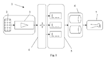
- the system has a surface EMG sensor array 2, amplification and filtering section 3, the upper layer control system 4, the lower level control system 5, the activation block 6, and the prosthetic hand device 7.
- a hierarchical controller 1 having five sections, namely the surface EMG sensor array 2, the amplification and filtering section 3, the upper layer control system 4, the lower level control system 5, the activation block 6, and the prosthetic hand mechanism 7.
- the surface EMG sensor array 2 collects the skin surface electrical potential resulting from the human muscle activation.
- the sensors combine the signals based on the spatial location where the individual is located with respect to a muscle.
- the amplification and filtering 3 is performed by using a notch filter removing low and high frequency components from the acquired signal.
- amplification and rectification of the sEMG signal is performed.
- the upper layer control system 4 is responsible for additional signal processing to format the filtered sEMG signal to a normalized size, which is used to identify what type of motion the prosthetic hand user intends to perform.
- the lower level control system 5 defines the actual movement of the individual joints of the prosthetic.
- the lower level control system 5 is responsible of determining the intended finger forces to be generated by the prosthetic hand device 7.
- the activation block 6 implements the joint motion and finger force commands by activating motors which drive the joints and generate torques and the resulting finger forces.
- the surface EMG sensor array 2 is designed by having a measure of an electrical potential between two points on the skin, with respect to a reference point, commonly placed at the outer part of the elbow.
- the two point measure is on the skin surface in the vicinity of the respective skeletal muscle responsible for a particular motion of a finger or set of fingers.
- the amplification and filtering 3 is designed by using amplifier circuitry and filtering circuitry. The rectification is performed as well using an amplification circuitry.
- the upper layer control system 4 and lower level control system 5 are embedded into a microcontroller.
- the activation block 6 is constructed by using electric motors with cabling to the individual joints of the prosthetic hand device 7.
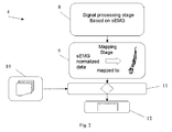
- the upper level control 4 is structured by a set of sequential processes.
- the sEMG signal obtained from the filtering unit 3 is processed by the signal processing stage 8, and mapped by the signal mapping stage 9.
- the mapped signal is submitted to the compare stage 11 that utilizes a classification table 10. This is then used in the motion set determination 12 stage.
- the signal processing stage 8 utilizes a number of mathematical operations to break down the filtered, rectified and amplified sEMG signal. The outcome of this process is than normalized in amplitude. The normalized signal is then mapped by the mapping stage 9 to classes of hand and finger motions. The outcome of the signal mapping stage 9 is compared in the compare stage 11 with the classification table 10. Based on the comparison 11, a motion set determination 12 is made.
- the upper level control 4 is implemented by using a microcontroller.
- the stages of signal processing 8, mapping 9, compare 11, and motion set determination 12 is programmed in equation form.
- the classification table 10 is stored in the microcontroller memory in tabular format.
- the lower level control 5 is composed of three stages, namely a motion intend stage 14, a model mapping stage 13, and a motion control 15 as well as a force control stage 16.
- the lower level control system 5 utilizes the information obtained from the upper level control 4 and the resulting motion determination set 12 to determine the motion intend stage 14.
- This stage 14 determines which joints and which fingers are being controlled.
- This information is then used in the mapping stage 13 of the lower level control system 5 to map the motions and forces to individual equations.
- These equations relate the dynamic relationship between the measured and processed 8 sEMG signal and the actual finger motion and finger forces.
- the finger/joint motions are determined by the motion control stage 15, while the finger forces are determined by the force control stage 16.
- the motion control stage 15 and the force control stage 16 drive the electric motors of the activation block 6.
- the lower level control 5 is implemented by using a microcontroller.
- the stages of motion intend stage 14, the model mapping stage 13, the motion control stage 15 and force control stage 16, are programmed in equation form.
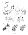
- the primary control input for the mechanical control 21 of the prosthetic hand device 7 are shoulder motions 25 and elbow motions 17. Some of the shoulder motions that are incorporate in the mechanical control are based on protraction 18, and retraction 19, where the shoulder blades 20 move in opposite directions. Some of the resulting prosthetic hand 7 motions are open hand 22, closed hand with thumb up 23, and grip with thumb outside 24. Fig. 4 details the depiction of one of the mechanical fingers 28 of the present invention 7, which contains tension 26 and loosening cables 27.
- the mechanical control 21 of the prosthetic hand device 7 is based on the motion created when the elbow 17 is rotated. This motion is transferred to the prosthetic hand device 7 via dual cables 26 and 27. These cables create a pull-pull affect that allows one of the cables 26 and 27 to be tensioned independent of the rotation of the elbow 17.
- cable 26 is tensioned and cable 27 is loosened.
- cable 27 is tensioned and cable 26 is loosened.
- Similar control of a different motion set of the invention 7 can be achieved using the shoulder motion 25.
- the motion is captured with a harness 29 and converted into tension in the Bowden cables 26, 27.
- the resulting force is then transferred into the designed motion in the prosthetic hand device 7 based on operator input. For example, the operator can go from an open hand 22 to a closed hand with thumb up 23 by moving their shoulders. All simple motions of the prosthetic hand device can be created by the combination of the three input methods, shoulder motion, elbow rotation, and sEMG signal.
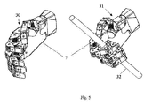
- FIG. 5 two particular motions of the prosthetic hand device 7 are depicted.
- the lateral motion 30 and the light tool motion 31 are depicted.
- the example object for the tool motion is a small cylinder 32.
- the first motion, lateral 30 is achieved using the hybrid control composed of the hierarchical controller 1 and mechanical controller 21.
- the light tool motion 31 can be achieved, i.e. using the hierarchical controller 1 and mechanical controller 21.
Landscapes
- Health & Medical Sciences (AREA)
- Transplantation (AREA)
- Biomedical Technology (AREA)
- Cardiology (AREA)
- Oral & Maxillofacial Surgery (AREA)
- Engineering & Computer Science (AREA)
- Heart & Thoracic Surgery (AREA)
- Vascular Medicine (AREA)
- Life Sciences & Earth Sciences (AREA)
- Animal Behavior & Ethology (AREA)
- General Health & Medical Sciences (AREA)
- Public Health (AREA)
- Veterinary Medicine (AREA)
- Orthopedic Medicine & Surgery (AREA)
- Prostheses (AREA)
Abstract
Description
- The present invention is in the technical field of prosthetic devices. More particularly, the present invention is in the technical field of hand prosthetic devices using shoulder harness and electromyographic (EMG) based activation and control.
- Current statistics about trans-radial amputation indicates upper limb prosthetics is in high demands. A lot of effort has been placed on research dealing with advanced prosthetic devices. However, up to date there are no prosthetic devices available that mimic the full functionality of a human hand. There are multiple types of hand prostheses. In most cases these devices are controlled using a shoulder harness that allows the operator to capture shoulder or elbow movements and translate these into a mechanical opening and closing of a hook or clamp that is used to give some ability back to the amputee. Another type of prosthetic hand device is based on measuring surface Electromyographic (sEMG) signals to initiate the actuation of the prosthetic device. Since sEMG signals are spatially distributed, the sEMG probes pick up signals from other motor units stemming from different muscle groups. This phenomenon is called crosstalk, which is a major cause for the difficulty in interpreting the intended hand/finger motion. EMG signals are generated by the simultaneous firing of several motor units during muscle contraction. Before reaching the skin surface, the EMG signal passes through numerous layers of tissues, which leads to noise and interference in the signal acquisition. The random nature of the sEMG signal represents an added complexity in studying it. All of these issues make it rather complex to distinguish the content of the sEMG signal against noise and interference.
- Prosthetic devices have been developed with the aim of matching the human hand in terms of dexterity and adaptation capabilities. Prosthetic hands are often designed to equip a dexterous manipulator for pick-and-place tasks or full mechanical designs that use other motion of the body - typically shoulder or elbow motion - to create a gripping motion in prosthetic devices. Both types of devices have been shown to give some functionality back to an amputee. In manipulator pick-and-place devices, the prosthetic device looks and feels like the human hand and can create human hand like function. However, training and fitting of these devices is cumbersome and often times the amputee will part from using the device in as little as two years. Full mechanical design prosthetics provide robust designs that simplify the human hand function down to the simplicity of a simple hook that has the ability to pinch an object. These designs have become the fall back choice for most amputees.
- The devise that is described in this application is a hybrid version of the systems described above. It has both mechanical actuation functions, such as typical mechanical prosthetic devices possess with the dexterous manipulator, and actuation function controlled by the use of sEMG signals. The present invention has the ability to control hand motion by both types of actuation. This allows the amputee to us the mechanical controls/actuation to help train mussels when actuating the prosthetic with sEMG signals. It also allows the amputee to choose what type of actuation (sEMG, mechanical, or both at the same time) he or she desires for a particular task, making the system adaptive to the user.
- The present invention is a hybrid prosthetic hand capable of controlling the motion set of a prosthetic device through sEMG signals as well as through the motion of the respective shoulder and elbow of the prosthetic hand user.
- The mechanical functions of the present invention are controlled by either a shrugging shoulder motion, elbow straitening or collapsing motion, or both. The forces provided by these motions are transferred to hand using a Bowden cable design. The operator can then chose what this motion will do in the hand function, allowing the system to adapt to the amputee's personal ability and desired task.
- The second type for controlling the prosthetic device is given by using the sEMG signals. In this mode, the present invention utilizes a hierarchical control structure, where classification of sEMG signals are used to infer the general motion set, and sEMG signals-motion as well as sEMG signal-force models are used to control the intricate motion of individual joints of the prosthetic device.
- A third option of controlling the prosthetic device is given by evoking both approaches described above at the same time as a hybrid mode, i.e. using the shoulder harness or elbow harness, in addition to the sEMG signal as control input for the prosthetic device.
-
-
Fig. 1 is a depiction of the hierarchical control structure. -
Fig. 2 is a view of the upper level control of the hierarchical controller. -
Fig. 3 is a depiction of the lower level control of the hierarchical controller. -
Fig. 4 is a depiction of the mechanical input and function of the invention. -
Fig. 5 is a view of some of the advanced capabilities of the invention. - The sEMG based control system uses a hierarchical architecture that utilizes two approaches to infer the intended motion for the prosthetic device. The "upper" level control is based on a classification scheme, where a set of sEMG sensor signals allow for categorizing what type of motion is intended by the user. With this information, the set of joints and links that are being controlled are identified. The second layer is the joint motion control layer. The control structure for this layer is such that individual joint positions and motions are directly controlled through a set of dynamic models representing the relationship between the sEMG signal and the joint motion. A second set of models is used to relate the intended finger tip forces with the measured sEMG signals.
- Referring to the invention given in
Fig. 1 the components of the hierarchical control architecture are depicted 1. The system has a surface EMG sensor array 2, amplification andfiltering section 3, the upperlayer control system 4, the lowerlevel control system 5, theactivation block 6, and theprosthetic hand device 7. - Referring now to the invention in more detail, in
Fig. 1 there is shown ahierarchical controller 1 having five sections, namely the surface EMG sensor array 2, the amplification andfiltering section 3, the upperlayer control system 4, the lowerlevel control system 5, theactivation block 6, and theprosthetic hand mechanism 7. The surface EMG sensor array 2 collects the skin surface electrical potential resulting from the human muscle activation. The sensors combine the signals based on the spatial location where the individual is located with respect to a muscle. The amplification andfiltering 3 is performed by using a notch filter removing low and high frequency components from the acquired signal. In addition, in thisstage 3, amplification and rectification of the sEMG signal is performed. The upperlayer control system 4 is responsible for additional signal processing to format the filtered sEMG signal to a normalized size, which is used to identify what type of motion the prosthetic hand user intends to perform. The lowerlevel control system 5 defines the actual movement of the individual joints of the prosthetic. In addition, the lowerlevel control system 5 is responsible of determining the intended finger forces to be generated by theprosthetic hand device 7. Theactivation block 6 implements the joint motion and finger force commands by activating motors which drive the joints and generate torques and the resulting finger forces. - In further detail, still referring to the invention of
Fig. 1 , the surface EMG sensor array 2 is designed by having a measure of an electrical potential between two points on the skin, with respect to a reference point, commonly placed at the outer part of the elbow. The two point measure is on the skin surface in the vicinity of the respective skeletal muscle responsible for a particular motion of a finger or set of fingers. The amplification andfiltering 3 is designed by using amplifier circuitry and filtering circuitry. The rectification is performed as well using an amplification circuitry. The upperlayer control system 4 and lowerlevel control system 5 are embedded into a microcontroller. Theactivation block 6 is constructed by using electric motors with cabling to the individual joints of theprosthetic hand device 7. - Referring now to
Fig. 2 , theupper level control 4 is structured by a set of sequential processes. The sEMG signal obtained from thefiltering unit 3 is processed by thesignal processing stage 8, and mapped by thesignal mapping stage 9. The mapped signal is submitted to the comparestage 11 that utilizes a classification table 10. This is then used in the motion setdetermination 12 stage. - In more detail, still referring to the invention in
Fig. 2 , thesignal processing stage 8 utilizes a number of mathematical operations to break down the filtered, rectified and amplified sEMG signal. The outcome of this process is than normalized in amplitude. The normalized signal is then mapped by themapping stage 9 to classes of hand and finger motions. The outcome of thesignal mapping stage 9 is compared in the comparestage 11 with the classification table 10. Based on thecomparison 11, a motion setdetermination 12 is made. - In further detail, still referring to the invention of
Fig. 2 , theupper level control 4 is implemented by using a microcontroller. The stages ofsignal processing 8,mapping 9, compare 11, and motion setdetermination 12 is programmed in equation form. The classification table 10 is stored in the microcontroller memory in tabular format. - Referring now to
Fig. 3 , thelower level control 5 is composed of three stages, namely a motion intendstage 14, amodel mapping stage 13, and amotion control 15 as well as aforce control stage 16. - In more detail, still referring to the invention of
Fig. 3 , the lowerlevel control system 5 utilizes the information obtained from theupper level control 4 and the resulting motion determination set 12 to determine the motion intendstage 14. Thisstage 14 determines which joints and which fingers are being controlled. This information is then used in themapping stage 13 of the lowerlevel control system 5 to map the motions and forces to individual equations. These equations relate the dynamic relationship between the measured and processed 8 sEMG signal and the actual finger motion and finger forces. The finger/joint motions are determined by themotion control stage 15, while the finger forces are determined by theforce control stage 16. Themotion control stage 15 and theforce control stage 16 drive the electric motors of theactivation block 6. - In further detail, still referring to the invention of
Fig. 3 , thelower level control 5 is implemented by using a microcontroller. The stages of motion intendstage 14, themodel mapping stage 13, themotion control stage 15 andforce control stage 16, are programmed in equation form. - Referring to the invention given in
Fig. 4 , the primary control input for themechanical control 21 of theprosthetic hand device 7 areshoulder motions 25 andelbow motions 17. Some of the shoulder motions that are incorporate in the mechanical control are based onprotraction 18, andretraction 19, where theshoulder blades 20 move in opposite directions. Some of the resultingprosthetic hand 7 motions areopen hand 22, closed hand with thumb up 23, and grip with thumb outside 24.Fig. 4 details the depiction of one of themechanical fingers 28 of thepresent invention 7, which containstension 26 and looseningcables 27. - In more detail, still referring to the invention of
Fig. 4 , themechanical control 21 of theprosthetic hand device 7, is based on the motion created when theelbow 17 is rotated. This motion is transferred to theprosthetic hand device 7 viadual cables cables elbow 17. When theelbow 17 is rotated in onedirection cable 26 is tensioned andcable 27 is loosened. When theelbow 17 is rotated in the opposite direction,cable 27 is tensioned andcable 26 is loosened. Similar control of a different motion set of theinvention 7 can be achieved using theshoulder motion 25. As the amputee moves theirshoulders 20, the motion is captured with aharness 29 and converted into tension in theBowden cables prosthetic hand device 7 based on operator input. For example, the operator can go from anopen hand 22 to a closed hand with thumb up 23 by moving their shoulders. All simple motions of the prosthetic hand device can be created by the combination of the three input methods, shoulder motion, elbow rotation, and sEMG signal. - Referring now to
Fig. 5 , two particular motions of theprosthetic hand device 7 are depicted. Thelateral motion 30 and thelight tool motion 31 are depicted. The example object for the tool motion is asmall cylinder 32. - In more detail, still referring to the invention of
Fig. 5 , the first motion, lateral 30 is achieved using the hybrid control composed of thehierarchical controller 1 andmechanical controller 21. In the same fashion, thelight tool motion 31 can be achieved, i.e. using thehierarchical controller 1 andmechanical controller 21. - While the foregoing written description of the invention enables one of ordinary skill to make and use what is considered presently to be the best mode thereof, those of ordinary skill will understand and appreciate the existence of variations, combinations, and equivalents of the specific embodiment, method, and examples herein. The invention should therefore not be limited by the above described embodiment, method, and examples, but by all embodiments and methods within the scope and spirit of the invention as claimed.
Claims (6)
- A hybrid prosthetic hand for an amputee comprising:an EMG sensor array, said EMG sensor array configured to capture data via sEMG signals,a microcontroller;a mechanical controller;a hierarchical controller;at least one tension cable;at least one loosening cable;at least one Bowden cable;at least one electric motor;a harness, wherein said harness is in communication with the amputee;wherein said mechanical controller is configured to receive input from said harness;wherein said microcontroller is configured to convert said data from said EMG sensor array into instructions for said hierarchical controller;wherein said at least one tension cable is strained upon movement of an elbow of the amputee;mechanical fingers, wherein said mechanical fingers are moved by said Bowden cables via said at least one electric motor when instructed by said hierarchical controller;wherein said mechanical fingers are moved by said Bowden cables when instructed by said mechanical controller via a shoulder of the amputee; andwherein all movement of said mechanical fingers is enacted via three input methods selected from the following: motion of the shoulder, rotation of the elbow, sEMG signal.
- The hybrid prosthetic hand for an amputee of claim 1, wherein said harness is in communication with the shoulder of the amputee.
- The hybrid prosthetic hand for an amputee of claim 1, wherein said harness is in communication with the elbow of the amputee.
- The hybrid prosthetic hand for an amputee of claim 1, wherein said at least one electric motor in in communication with said mechanical fingers.
- The hybrid prosthetic hand for an amputee of claim 1, further comprising:a motion intend stage;a model mapping stage;a motion control stage;a force control stage;wherein said motion intend stage, said model mapping stage, said motion control stage, and said force control stage are regulated by said microcontroller;wherein said motion control stage and said force control stage are configured to determine the extent to which said mechanical fingers move; andwherein said motion control stage and said force control stage are configured to determine the extent of force applied to said mechanical fingers.
- The hybrid prosthetic hand for an amputee of claim 5, wherein lateral movement of said harness and said mechanical fingers is achieved via instructions from said hierarchical controller and said mechanical controller.
Applications Claiming Priority (1)
| Application Number | Priority Date | Filing Date | Title |
|---|---|---|---|
| US14/061,646 US20150112448A1 (en) | 2013-10-23 | 2013-10-23 | Hybrid Prosthetic Hand |
Publications (1)
| Publication Number | Publication Date |
|---|---|
| EP2865356A1 true EP2865356A1 (en) | 2015-04-29 |
Family
ID=51830203
Family Applications (1)
| Application Number | Title | Priority Date | Filing Date |
|---|---|---|---|
| EP20140190163 Withdrawn EP2865356A1 (en) | 2013-10-23 | 2014-10-23 | Hybrid prosthetic hand |
Country Status (3)
| Country | Link |
|---|---|
| US (1) | US20150112448A1 (en) |
| EP (1) | EP2865356A1 (en) |
| CN (1) | CN104546235B (en) |
Families Citing this family (13)
| Publication number | Priority date | Publication date | Assignee | Title |
|---|---|---|---|---|
| US10034780B2 (en) | 2014-02-04 | 2018-07-31 | Rehabilitation Institute Of Chicago | Modular and lightweight myoelectric prosthesis components and related methods |
| US10559864B2 (en) | 2014-02-13 | 2020-02-11 | Birmingham Technologies, Inc. | Nanofluid contact potential difference battery |
| GB201403265D0 (en) | 2014-02-25 | 2014-04-09 | Touch Emas Ltd | Prosthetic digit for use with touchscreen devices |
| US10271966B2 (en) * | 2016-03-16 | 2019-04-30 | Ryan William Glasgow | Mechanical prosthetic hand |
| CN105943206A (en) * | 2016-06-01 | 2016-09-21 | 上海师范大学 | Prosthetic hand control method based on MYO armlet |
| CN106264806B (en) * | 2016-08-16 | 2018-08-07 | 文浩 | A kind of simulation manipulator and control method |
| CN107049570A (en) * | 2017-03-13 | 2017-08-18 | 日照若比邻机器人科技有限公司 | Manipulator control system |
| RU2664171C1 (en) * | 2017-07-26 | 2018-08-15 | Максим Александрович Ляшко | Arm prosthesis for patients with the degree of amputation from fingers to the forearm, prosthesis of the wrist joint, which includes the hand prosthesis, the finger rod cable locking device of the hand prosthesis (3 options), the finger position combination control device of the hand prosthesis (2 options) |
| US10973660B2 (en) | 2017-12-15 | 2021-04-13 | Touch Bionics Limited | Powered prosthetic thumb |
| CN108673534B (en) * | 2018-04-20 | 2020-11-03 | 江苏大学 | Software manipulator for realizing intelligent sorting by using artificial synapse network system |
| SE1851567A1 (en) | 2018-12-12 | 2020-06-13 | Tendo Ab | Control of an active orthotic device |
| US11931270B2 (en) | 2019-11-15 | 2024-03-19 | Touch Bionics Limited | Prosthetic digit actuator |
| WO2024150041A1 (en) * | 2023-01-14 | 2024-07-18 | Life And Limb Private Limited | An upper limb prosthetic hand for transradial amputee |
Citations (4)
| Publication number | Priority date | Publication date | Assignee | Title |
|---|---|---|---|---|
| US5376128A (en) * | 1992-08-31 | 1994-12-27 | The United States Of America As Represented By The Administrator Of The National Aeronautics And Space Administration | Control system for prosthetic devices |
| WO2008098059A2 (en) * | 2007-02-06 | 2008-08-14 | Deka Integrated Solutions Corp. | Method and apparatus for control of a prosthetic |
| WO2011020446A1 (en) * | 2009-08-21 | 2011-02-24 | The Chinese University Of Hong Kong | Systems and methods for reproducing body motions via networks |
| WO2012071343A1 (en) * | 2010-11-22 | 2012-05-31 | Vanderbilt University | Control system for a grasping device |
Family Cites Families (15)
| Publication number | Priority date | Publication date | Assignee | Title |
|---|---|---|---|---|
| US5888213A (en) * | 1997-06-06 | 1999-03-30 | Motion Control, Inc. | Method and apparatus for controlling an externally powered prosthesis |
| US6171239B1 (en) * | 1998-08-17 | 2001-01-09 | Emory University | Systems, methods, and devices for controlling external devices by signals derived directly from the nervous system |
| AU2001220214A1 (en) * | 2000-12-19 | 2002-07-01 | Alorman-Advanced Medical Technologies Ltd. | Method for controlling multi-function myoelectric prothesis |
| US6660042B1 (en) * | 2001-02-02 | 2003-12-09 | Rutgers, The State University Of New Jersey | Methods of biomimetic finger control by filtering of distributed forelimib pressures |
| US8864845B2 (en) * | 2007-02-06 | 2014-10-21 | DEKA Limited Partnership | System for control of a prosthetic device |
| US9114030B2 (en) * | 2007-02-06 | 2015-08-25 | Deka Products Limited Partnership | System for control of a prosthetic device |
| US8170656B2 (en) * | 2008-06-26 | 2012-05-01 | Microsoft Corporation | Wearable electromyography-based controllers for human-computer interface |
| US9265625B2 (en) * | 2009-08-20 | 2016-02-23 | Vanderbilt University | Jointed mechanical devices |
| US8840680B2 (en) * | 2009-08-20 | 2014-09-23 | Vanderbilt University | Control system for jointed mechanical devices |
| CN101995947B (en) * | 2009-08-21 | 2012-07-04 | 香港中文大学 | Systems and methods for reproducing body motions via networks |
| GB0916895D0 (en) * | 2009-09-25 | 2009-11-11 | Touch Emas Ltd | Prosthetic apparatus and method |
| CN102426651B (en) * | 2011-08-25 | 2014-04-16 | 武汉理工大学 | Human body forearm surface electromyogram signal acquisition and pattern recognition system |
| CN102961203B (en) * | 2012-12-10 | 2015-04-22 | 杭州电子科技大学 | Method for identifying surface electromyography (sEMG) on basis of empirical mode decomposition (EMD) sample entropy |
| US20140277583A1 (en) * | 2013-03-15 | 2014-09-18 | The Florida International University Board Of Trustees | Fitting system for a neural enabled limb prosthesis system |
| ES2661538T3 (en) * | 2013-06-12 | 2018-04-02 | Otto Bock Healthcare Gmbh | Limb device control |
-
2013
- 2013-10-23 US US14/061,646 patent/US20150112448A1/en not_active Abandoned
-
2014
- 2014-02-21 CN CN201410060110.7A patent/CN104546235B/en not_active Expired - Fee Related
- 2014-10-23 EP EP20140190163 patent/EP2865356A1/en not_active Withdrawn
Patent Citations (4)
| Publication number | Priority date | Publication date | Assignee | Title |
|---|---|---|---|---|
| US5376128A (en) * | 1992-08-31 | 1994-12-27 | The United States Of America As Represented By The Administrator Of The National Aeronautics And Space Administration | Control system for prosthetic devices |
| WO2008098059A2 (en) * | 2007-02-06 | 2008-08-14 | Deka Integrated Solutions Corp. | Method and apparatus for control of a prosthetic |
| WO2011020446A1 (en) * | 2009-08-21 | 2011-02-24 | The Chinese University Of Hong Kong | Systems and methods for reproducing body motions via networks |
| WO2012071343A1 (en) * | 2010-11-22 | 2012-05-31 | Vanderbilt University | Control system for a grasping device |
Also Published As
| Publication number | Publication date |
|---|---|
| CN104546235A (en) | 2015-04-29 |
| CN104546235B (en) | 2017-01-04 |
| US20150112448A1 (en) | 2015-04-23 |
Similar Documents
| Publication | Publication Date | Title |
|---|---|---|
| EP2865356A1 (en) | Hybrid prosthetic hand | |
| Zhang et al. | Design and functional evaluation of a dexterous myoelectric hand prosthesis with biomimetic tactile sensor | |
| US10543111B2 (en) | Biomimetic controller for increased dexterity prosthesis | |
| EP2642953B1 (en) | Control system for a grasping device | |
| Antfolk et al. | Using EMG for real-time prediction of joint angles to control a prosthetic hand equipped with a sensory feedback system | |
| CN107127735A (en) | People's demonstration formula has the robot learning of power and position purpose task | |
| Romeo et al. | Method for automatic slippage detection with tactile sensors embedded in prosthetic hands | |
| EP3003226A2 (en) | Postural control of a multi-function prosthesis | |
| CN113171214B (en) | Multi-path feedback myoelectric control prosthetic hand based on self-adaptive enhancement classifier and method | |
| Alshamsi et al. | Development of a local prosthetic limb using artificial intelligence | |
| Li et al. | Transcend anthropomorphic robotic grasping with modular antagonistic mechanisms and adhesive soft modulations | |
| Ryait et al. | Study of issues in the development of surface EMG controlled human hand | |
| CN111897415A (en) | Virtual artificial hand compliance visual control method based on electromyographic signals and variable stiffness control | |
| Vujaklija | Novel control strategies for upper limb prosthetics | |
| Akhmadeev et al. | A real-time gesture classification using surface EMG to control a robotics hand | |
| Sriram et al. | Slippage control for a smart prosthetic hand prototype via modified tactile sensory feedback | |
| Castellini et al. | EMG-based prediction of multi-DOF activations using single-DOF training: a preliminary result | |
| Matrone et al. | Bio-inspired controller for a dexterous prosthetic hand based on principal components analysis | |
| Ossaba et al. | Open source multichannel EMG armband design | |
| Tsuji et al. | Biomimetic impedance control of an EMG-based robotic hand | |
| Peerdeman et al. | Development of underactuated prosthetic fingers with joint locking and electromyographic control | |
| Yahud et al. | Prosthetic hand for the brain-computer interface system | |
| Lai et al. | Design of a multi-degree-of-freedom virtual hand bench for myoelectrical prosthesis | |
| Bimbraw et al. | Towards The Development of a Low-Latency, Biosignal-Controlled Human-Machine Interaction System | |
| Gohain et al. | EMG controlled adaptive multi-grasp prosthetic hand with an android interface |
Legal Events
| Date | Code | Title | Description |
|---|---|---|---|
| PUAI | Public reference made under article 153(3) epc to a published international application that has entered the european phase |
Free format text: ORIGINAL CODE: 0009012 |
|
| 17P | Request for examination filed |
Effective date: 20141023 |
|
| AK | Designated contracting states |
Kind code of ref document: A1 Designated state(s): AL AT BE BG CH CY CZ DE DK EE ES FI FR GB GR HR HU IE IS IT LI LT LU LV MC MK MT NL NO PL PT RO RS SE SI SK SM TR |
|
| AX | Request for extension of the european patent |
Extension state: BA ME |
|
| R17P | Request for examination filed (corrected) |
Effective date: 20151029 |
|
| RBV | Designated contracting states (corrected) |
Designated state(s): AL AT BE BG CH CY CZ DE DK EE ES FI FR GB GR HR HU IE IS IT LI LT LU LV MC MK MT NL NO PL PT RO RS SE SI SK SM TR |
|
| 17Q | First examination report despatched |
Effective date: 20171009 |
|
| STAA | Information on the status of an ep patent application or granted ep patent |
Free format text: STATUS: THE APPLICATION IS DEEMED TO BE WITHDRAWN |
|
| 18D | Application deemed to be withdrawn |
Effective date: 20180220 |