EP2865276A1 - Cooker device for the transferring, moving and at least partial cooking of food products - Google Patents
Cooker device for the transferring, moving and at least partial cooking of food products Download PDFInfo
- Publication number
- EP2865276A1 EP2865276A1 EP20140186236 EP14186236A EP2865276A1 EP 2865276 A1 EP2865276 A1 EP 2865276A1 EP 20140186236 EP20140186236 EP 20140186236 EP 14186236 A EP14186236 A EP 14186236A EP 2865276 A1 EP2865276 A1 EP 2865276A1
- Authority
- EP
- European Patent Office
- Prior art keywords
- product
- outlet
- drum
- cup
- unloading
- Prior art date
- Legal status (The legal status is an assumption and is not a legal conclusion. Google has not performed a legal analysis and makes no representation as to the accuracy of the status listed.)
- Granted
Links
Images




Classifications
-
- A—HUMAN NECESSITIES
- A23—FOODS OR FOODSTUFFS; TREATMENT THEREOF, NOT COVERED BY OTHER CLASSES
- A23N—MACHINES OR APPARATUS FOR TREATING HARVESTED FRUIT, VEGETABLES OR FLOWER BULBS IN BULK, NOT OTHERWISE PROVIDED FOR; PEELING VEGETABLES OR FRUIT IN BULK; APPARATUS FOR PREPARING ANIMAL FEEDING- STUFFS
- A23N12/00—Machines for cleaning, blanching, drying or roasting fruits or vegetables, e.g. coffee, cocoa, nuts
- A23N12/02—Machines for cleaning, blanching, drying or roasting fruits or vegetables, e.g. coffee, cocoa, nuts for washing or blanching
- A23N12/04—Machines for cleaning, blanching, drying or roasting fruits or vegetables, e.g. coffee, cocoa, nuts for washing or blanching for blanching
-
- A—HUMAN NECESSITIES
- A23—FOODS OR FOODSTUFFS; TREATMENT THEREOF, NOT COVERED BY OTHER CLASSES
- A23L—FOODS, FOODSTUFFS OR NON-ALCOHOLIC BEVERAGES, NOT OTHERWISE PROVIDED FOR; PREPARATION OR TREATMENT THEREOF
- A23L5/00—Preparation or treatment of foods or foodstuffs, in general; Food or foodstuffs obtained thereby; Materials therefor
- A23L5/10—General methods of cooking foods, e.g. by roasting or frying
- A23L5/13—General methods of cooking foods, e.g. by roasting or frying using water or steam
Definitions
- the present finding is inserted in the food field and specifically in the field of plants/apparatuses and systems for moving and transferring foods and the processing thereof.
- the invention regards a cooler-cooker apparatus, capable of receiving, moving and at least partially cooking one or more semifinished food products, releasing them at the end towards a line downstream of the cooker itself.
- Cooker devices or apparatuses for industrial use are known which are suitable for executing at least one partial cooking cycle of food products. Examples of these include the patents US7735415 and US8006613 .
- the devices of the prior art comprise a lower half-tank inside of which water is present maintained at a temperature (for cooking or scalding) by suitable heating and control means; in said tank, a drum is horizontally housed that is free to axially rotate.
- the drum bears a central rotation shaft, along which a thread is extended that is adapted to obtain a screw such that, once the product is loaded from a loading end, this is situated immersed in the cooking water, to be advanced following the actuation of the rotating drum.
- the final part corresponds with the product unloading; said unloading step occurs with a plurality of cups, distributed on a wheel and which are immersed in the water, loading the incoming product and unloading it towards the outside or in a suitable drainage chute.
- Object of the present finding is to remedy the above-lamented drawbacks by providing the art with a device and system for moving and cooking food products which:
- the first object is resolved with the use of a cooker drum having not one but multiple screws, i.e. multiple threads, in the technical jargon multiple starts, on the rotation shaft; this reduces by 1/2, 1/3, 1/N (where N is the number of starts) the possible stay time of the product before its advancement in the tank, due to the thread itself.
- the conformation of the inlet of the rotating drum does not allow the product to be able to jump over any of the advancement starts, since the zone is delimited by a partition that requires the incoming product to fall in the first start, and in this manner one can ensure that the entire product that will enter in the cooker will pass the same time in the cooking water.
- each start ends with an unloading cup thereof, integral therewith ensures that all of the incoming product will then be unloaded at the cooker outlet, without leaving remnants in the cooker tank.
- the second object of the present invention is resolved by arranging an unloading cup or blade integral with each thread present on the drum; this ensures that all the product advancing with that thread is evacuated as soon as it reaches the outlet zone.
- reference number 1 indicates overall a cooker device for the transferring, moving and the at least partial cooking of food products to be packaged or further processed in a line downstream.
- the device comprises at least one lower half-tank 2 within which water is introduced in the operative step, with recirculation systems that are already known and hence lie outside the present invention.
- the water will be at the temperature suitable for inducing a cooking or pre-cooking on the food product introduced in a loading zone I and exiting from an unloading zone U.
- the device 1 bears means C, for the recirculation and maintenance of the water at the temperature set inside the tank 2.
- the half-tank is closable with a cover, indicated with 7, so as to isolate the machine and keep it clean during the operating steps thereof.
- a product advancement drum 3 comprising, in the example, three starts or threads indicated with 4, 5 and 6; said starts are offset from each other: in such a manner, each 120° the loading is ensured also of the product that may not have been loaded from the inlet I (in this case a chute), precisely in the set thread.
- the drum 3 bears a shaft 8 situated substantially horizontal inside the machine 1.
- the drum 3 is controllable in axial rotation by means of known type such that, following the axial rotation AA, each thread 4, 5, 6 drives the product forward towards the outlet U placed at the opposite end.
- the drum In operative conditions, the drum is partially immersed in the water.
- the product is made to advance from the starts 4, 5, 6, floating in the water it is also cooked according to the stay time necessary for completing the travel to the outlet U of the machine.
- each thread 4, 5, 6 comprises a system of walls such to act as collection cups T integral with the drum and which are immersed in the water, loading the incoming product and unloading it to the outside or in a suitable drainage chute.
- the cups unload the product when they are situated at the outlet U of the device.
- Each cup T is integral with the respective thread 4, 5, 6.
- FIGS 2 and 3 illustrate in detail the conformation of the drum 3, i.e. its three starts which contribute to forming the advancement screw and the three cups T.
- each cup T in the present invention is that of acting as a product collection blade contained within each start and such to facilitate the thrust towards the outlet.
- the conformation of the unloading cup T or blade placed at the end of each start 4, 5, 6 confers an axial thrust to the product that is essential for the exit of the product from the tank.
- the cup T is not conceived as a simple collection blade, rather it is shaped in a manner such that said shape allows the product to be directed towards the outlet, thus considerably improving the unloading operations.
- the cup is substantially configured as a blade, with two adjacent portions 11 and 12 that are bent with respect to each other; the portion indicated in the figure with 11 is the blade portion that is directly attached to the respective start or thread of the screw, the portion 12 is bent towards the outlet and forms with said first portion 11 a bend angle, indicated with 14, that is less than 90°.
- said portion 12 which is the surface on which the product is accumulated before unloading
- one edge 13 thereof is further bent in a manner so as to create an angle 15 with said surface; said angle 15 is less than 180°; a preferred value, as in the figure, is 175°; in any case, said tilt different from that of a flat angle between the surfaces 12 and 13 is such to allow an effective action of lifting of the product and unloading towards the outlet U.
- the cups T unload the product on a channel on a vibrating conduit 10 downstream of the device 1.
- the partitions 11, 12, 13 have a plurality of holes for the drainage of the cooking water.
- the edge 13 is extended for a length L1 less than or equal to half the length L2 of the surface 12.
Landscapes
- Life Sciences & Earth Sciences (AREA)
- Chemical & Material Sciences (AREA)
- Engineering & Computer Science (AREA)
- Food Science & Technology (AREA)
- Polymers & Plastics (AREA)
- Health & Medical Sciences (AREA)
- Nutrition Science (AREA)
- Commercial Cooking Devices (AREA)
- Apparatuses For Bulk Treatment Of Fruits And Vegetables And Apparatuses For Preparing Feeds (AREA)
- Food-Manufacturing Devices (AREA)
- Baking, Grill, Roasting (AREA)
- General Preparation And Processing Of Foods (AREA)
Abstract
a. at least one lower half-tank (2) which receives cooking water in the operative step,
b. a loading zone (I) and, at the outlet, an unloading zone (U),
c. a product advancement drum (3) immersed in the water, for product advancement from the inlet point (I) to the outlet point (U), by means of a product advancement screw; said drum (3) controllable in axial rotation (AA) by means of known type; in operative conditions, the drum is partially immersed in the water. The drum (3) comprises multiple starts (4, 5, 6) or threads equidistant from each other and each start or thread (4, 5, 6), at the outlet section (U), comprises a collection cup (T) which unloads the product, if in communication with the outlet (U) of the device. Each cup is integral with the respective thread.
Description
- The present finding is inserted in the food field and specifically in the field of plants/apparatuses and systems for moving and transferring foods and the processing thereof.
- Specifically, the invention regards a cooler-cooker apparatus, capable of receiving, moving and at least partially cooking one or more semifinished food products, releasing them at the end towards a line downstream of the cooker itself.
- It is known to operate by cooking, inside a tank, the product to be packaged, so as to operate on the latter at least one step of cooking and/or scalding, after which the food product:
- is transferred towards a further processing system,
- is cooled and then packaged.
-
- The devices of the prior art comprise a lower half-tank inside of which water is present maintained at a temperature (for cooking or scalding) by suitable heating and control means; in said tank, a drum is horizontally housed that is free to axially rotate.
- The drum bears a central rotation shaft, along which a thread is extended that is adapted to obtain a screw such that, once the product is loaded from a loading end, this is situated immersed in the cooking water, to be advanced following the actuation of the rotating drum.
- The final part corresponds with the product unloading; said unloading step occurs with a plurality of cups, distributed on a wheel and which are immersed in the water, loading the incoming product and unloading it towards the outside or in a suitable drainage chute.
- The defects of the prior art are of two types:
- A first drawback regards the product advancement screw which is of the type with only one start, i.e. only one thread; it may occur that a certain quantity of product is not exactly inserted upon the passage of the set thread, with the consequence that the product remains for a longer or shorter time according to the position where it is situated upon passage of the thread.
- A second drawback regards the product loading cups; the latter are not closed and do not ensure the effective loading of all the product at the end of the transfer step, i.e. at the end of cooking.
- It follows that extremely non-uniform products will be obtained, some more cooked than others, with negative consequences for the final product quality; uniform cooking values of the packaged product cannot be ensured.
- Object of the present finding is to remedy the above-lamented drawbacks by providing the art with a device and system for moving and cooking food products which:
- ensures greater precision in the step of insertion at the screw inlet so as to have the product moving already at the passage of the corresponding thread, improving the precision of the cooking time;
- ensures the effective expulsion of the entire product at the end of the transfer step, i.e. at the end of cooking.
- The first object is resolved with the use of a cooker drum having not one but multiple screws, i.e. multiple threads, in the technical jargon multiple starts, on the rotation shaft; this reduces by 1/2, 1/3, 1/N (where N is the number of starts) the possible stay time of the product before its advancement in the tank, due to the thread itself.
- The conformation of the inlet of the rotating drum does not allow the product to be able to jump over any of the advancement starts, since the zone is delimited by a partition that requires the incoming product to fall in the first start, and in this manner one can ensure that the entire product that will enter in the cooker will pass the same time in the cooking water.
- In addition, the fact that each start ends with an unloading cup thereof, integral therewith, ensures that all of the incoming product will then be unloaded at the cooker outlet, without leaving remnants in the cooker tank.
- The second object of the present invention is resolved by arranging an unloading cup or blade integral with each thread present on the drum; this ensures that all the product advancing with that thread is evacuated as soon as it reaches the outlet zone.
- The conformation of the unloading cup or blade placed at the end of each start confers an axial thrust to the product that is essential for the exit of the product from the tank. Indeed this was not conceived as a simple collection blade, its particular shape allows the product to be directed towards the outlet, thus considerably improving the unloading operations.
- Hence, the advantages of the present finding are the following:
- improved cooking precision;
- effective expulsion of all the product at the end of the transfer step.
- Said objects and advantages are all attained by the device and system for moving and cooking food products, object of the present finding, which is characterized with regard to that provided in the below-reported claims.
- This and other characteristics will be clearer from the following description of several illustrated embodiments, as a merely non-limiting example in the enclosed drawing tables.
-
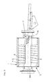
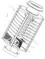
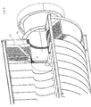
Figures 1 ,2 , and3 : illustrate the present cooker device, with loading and unloading system, object of the patent, i.e. with multiple starts and with product collection and unloading cup integral with each start. -
Figures 4 ,5 ,6 ,7 : illustrate details of the product unloading cups or blades placed integral with each thread and at the outlet; the particular conformation confers an axial thrust to the product that is essential for the exit of the product from the tank. - With particular reference to the figures, reference number 1 indicates overall a cooker device for the transferring, moving and the at least partial cooking of food products to be packaged or further processed in a line downstream.
- As the figures show, the device comprises at least one lower half-
tank 2 within which water is introduced in the operative step, with recirculation systems that are already known and hence lie outside the present invention. - The water will be at the temperature suitable for inducing a cooking or pre-cooking on the food product introduced in a loading zone I and exiting from an unloading zone U.
- The device 1 bears means C, for the recirculation and maintenance of the water at the temperature set inside the
tank 2. - The half-tank is closable with a cover, indicated with 7, so as to isolate the machine and keep it clean during the operating steps thereof.
- Inside, between the cover and tank, a
product advancement drum 3 is present comprising, in the example, three starts or threads indicated with 4, 5 and 6; said starts are offset from each other: in such a manner, each 120° the loading is ensured also of the product that may not have been loaded from the inlet I (in this case a chute), precisely in the set thread. - The
drum 3 bears ashaft 8 situated substantially horizontal inside the machine 1. - The
drum 3 is controllable in axial rotation by means of known type such that, following the axial rotation AA, eachthread - Means are not described here for placing the drum in rotation, nor are the water heating and control means described since these are already known to a man skilled in the art.
- In operative conditions, the drum is partially immersed in the water.
- The product is made to advance from the
starts - According to a variant embodiment, at the end of each start, and at the outlet section, each
thread - The cups unload the product when they are situated at the outlet U of the device.
- Each cup T is integral with the
respective thread -
Figures 2 and3 illustrate in detail the conformation of thedrum 3, i.e. its three starts which contribute to forming the advancement screw and the three cups T. - In the example, reference is made to a cooker device with three starts; nevertheless, protection is requested for a number of starts that is greater than 2.
- It is specified that the function of each cup T in the present invention is that of acting as a product collection blade contained within each start and such to facilitate the thrust towards the outlet.
- The conformation of the unloading cup T or blade placed at the end of each
start - In detail, and with reference to
figures 4 ,5 ,6 and7 , the shape of one of the cups T is described in detail. - The cup is substantially configured as a blade, with two
adjacent portions portion 12 is bent towards the outlet and forms with said first portion 11 a bend angle, indicated with 14, that is less than 90°. - With regard to said
portion 12, which is the surface on which the product is accumulated before unloading, it is observed that oneedge 13 thereof, particularly the edge directed towards the axis AA, is further bent in a manner so as to create anangle 15 with said surface; saidangle 15 is less than 180°; a preferred value, as in the figure, is 175°; in any case, said tilt different from that of a flat angle between thesurfaces - For such purpose, the presence is observed of a curved frame or partition 9 that is positioned in the outlet zone, cooperating for the product unloading action. The partition 9 is fixed.
- In the illustrated example, the cups T unload the product on a channel on a vibrating
conduit 10 downstream of the device 1. - The
partitions - Preferably the
edge 13 is extended for a length L1 less than or equal to half the length L2 of thesurface 12.
Claims (5)
- Cooker device (1) for the transferring, moving and the at least partial cooking of food products to be packaged or further processed in a line downstream, of the type comprisinga. at least one lower half-tank (2) which receives cooking water in the operative step,b. a loading zone (I) and, at the outlet, an unloading zone (U),c. a product advancement drum (3) immersed in the water, for product advancement from the inlet point (I) to the outlet point (U), by means of at least one product advancement screw; said drum (3) controllable in axial rotation (AA) by means of known type; in operative conditions, the drum is partially immersed in the water; the drum (3) is formed by two or more starts (4, 5, 6) or threads equidistant from each other;
the device being characterized in that each start or thread (4, 5, 6), at the outlet section (U), comprises an unloading cup or blade (T) which unloads the product at the outlet (U);
each cup (T) is integral with the respective thread; the conformation of the unloading cup (T) or blade placed at the end of each start confers an axial thrust to the product that is essential for the exit of the product from the tank (2). - Device according to claim 1 characterized in that said cup (T) comprises two adjacent portions (11) and (12) that are bent with respect to each other; while the portion (11) is directly integral with the respective start or thread (4, 5, 6) of the screw, the portion (12) is belt towards the outlet and forms, with said first portion (11), a bend angle (14) that is less than 90°; one edge (13) of said portion (12) of cup (T), i.e. the edge directed towards the axis (AA) of the device, is further bent in a manner so as to create an angle (15) with said surface (12); said angle (15) being less than 180°.
- Device according to claim 2 characterized in that said angle (15) is 175°.
- Device according to claims 1 and 2 characterized in that a curved frame or partition (9) is positioned in the outlet zone and cooperates with said cups (T) for the product unloading action; the partition (9) is fixed.
- Device according to claim 2 characterized in that the edge (13) is extended for a length (L1) less than or equal to half the length (L2) of the surface (12).
Applications Claiming Priority (1)
| Application Number | Priority Date | Filing Date | Title |
|---|---|---|---|
| IT000073A ITPR20130073A1 (en) | 2013-09-24 | 2013-09-24 | COOKER DEVICE FOR TRANSFER, HANDLING AND COOKING, AT LEAST PARTIAL, OF FOOD PRODUCTS |
Publications (2)
| Publication Number | Publication Date |
|---|---|
| EP2865276A1 true EP2865276A1 (en) | 2015-04-29 |
| EP2865276B1 EP2865276B1 (en) | 2020-05-27 |
Family
ID=49486581
Family Applications (1)
| Application Number | Title | Priority Date | Filing Date |
|---|---|---|---|
| EP14186236.7A Active EP2865276B1 (en) | 2013-09-24 | 2014-09-24 | Cooker device for transferring, moving and at least partial cooking of food products |
Country Status (7)
| Country | Link |
|---|---|
| EP (1) | EP2865276B1 (en) |
| AR (1) | AR099269A1 (en) |
| BR (1) | BR102014023681A2 (en) |
| IN (1) | IN2014DE02745A (en) |
| IT (1) | ITPR20130073A1 (en) |
| RU (1) | RU2014138482A (en) |
| ZA (1) | ZA201406962B (en) |
Cited By (2)
| Publication number | Priority date | Publication date | Assignee | Title |
|---|---|---|---|---|
| WO2023139443A1 (en) * | 2022-01-24 | 2023-07-27 | Staedler Automation Ag | Drum cooker |
| WO2023139442A1 (en) * | 2022-01-24 | 2023-07-27 | Staedler Automation Ag | Drum cooker |
Citations (8)
| Publication number | Priority date | Publication date | Assignee | Title |
|---|---|---|---|---|
| US2314871A (en) * | 1939-08-12 | 1943-03-30 | Chisholm Ryder Co Inc | Apparatus for treating foodstuffs |
| FR1575644A (en) * | 1967-04-05 | 1969-07-25 | ||
| US5341729A (en) * | 1993-09-23 | 1994-08-30 | Lyco Manufacturing, Inc. | Discharge for rotating drum blanchers and coolers |
| GB2298122A (en) * | 1995-02-22 | 1996-08-28 | Gen Mills Inc | Process for cooking cereal grains |
| US5752431A (en) * | 1996-10-15 | 1998-05-19 | Zittel; David R. | Blancher with multiple cooling zones |
| US20030230198A1 (en) * | 2002-06-14 | 2003-12-18 | Lyco Manufacturing, Inc. | Food processing apparatus, transport mechanism, bucket and method |
| US7735415B2 (en) | 2005-08-31 | 2010-06-15 | Lyco Manufacturing, Inc. | Rotary Screw blancher |
| US8006613B2 (en) | 2008-07-16 | 2011-08-30 | Lyco Manufacturing, Inc. | Transfer mechanism for use with a food processing system |
-
2013
- 2013-09-24 IT IT000073A patent/ITPR20130073A1/en unknown
-
2014
- 2014-09-23 ZA ZA2014/06962A patent/ZA201406962B/en unknown
- 2014-09-23 AR ARP140103507A patent/AR099269A1/en unknown
- 2014-09-23 RU RU2014138482A patent/RU2014138482A/en not_active Application Discontinuation
- 2014-09-24 EP EP14186236.7A patent/EP2865276B1/en active Active
- 2014-09-24 IN IN2745DE2014 patent/IN2014DE02745A/en unknown
- 2014-09-24 BR BR102014023681-3A patent/BR102014023681A2/en not_active Application Discontinuation
Patent Citations (8)
| Publication number | Priority date | Publication date | Assignee | Title |
|---|---|---|---|---|
| US2314871A (en) * | 1939-08-12 | 1943-03-30 | Chisholm Ryder Co Inc | Apparatus for treating foodstuffs |
| FR1575644A (en) * | 1967-04-05 | 1969-07-25 | ||
| US5341729A (en) * | 1993-09-23 | 1994-08-30 | Lyco Manufacturing, Inc. | Discharge for rotating drum blanchers and coolers |
| GB2298122A (en) * | 1995-02-22 | 1996-08-28 | Gen Mills Inc | Process for cooking cereal grains |
| US5752431A (en) * | 1996-10-15 | 1998-05-19 | Zittel; David R. | Blancher with multiple cooling zones |
| US20030230198A1 (en) * | 2002-06-14 | 2003-12-18 | Lyco Manufacturing, Inc. | Food processing apparatus, transport mechanism, bucket and method |
| US7735415B2 (en) | 2005-08-31 | 2010-06-15 | Lyco Manufacturing, Inc. | Rotary Screw blancher |
| US8006613B2 (en) | 2008-07-16 | 2011-08-30 | Lyco Manufacturing, Inc. | Transfer mechanism for use with a food processing system |
Cited By (2)
| Publication number | Priority date | Publication date | Assignee | Title |
|---|---|---|---|---|
| WO2023139443A1 (en) * | 2022-01-24 | 2023-07-27 | Staedler Automation Ag | Drum cooker |
| WO2023139442A1 (en) * | 2022-01-24 | 2023-07-27 | Staedler Automation Ag | Drum cooker |
Also Published As
| Publication number | Publication date |
|---|---|
| AR099269A1 (en) | 2016-07-13 |
| IN2014DE02745A (en) | 2015-06-26 |
| ZA201406962B (en) | 2015-12-23 |
| ITPR20130073A1 (en) | 2015-03-25 |
| EP2865276B1 (en) | 2020-05-27 |
| BR102014023681A2 (en) | 2017-11-07 |
| RU2014138482A (en) | 2016-04-10 |
Similar Documents
| Publication | Publication Date | Title |
|---|---|---|
| KR102044572B1 (en) | Method for producing instant fried noodles and frying treatment device | |
| EP3735834C0 (en) | Stirring unit for a machine for batch freezing and dispensing ice cream products, machine comprising the stirring unit and method for making ice cream products | |
| RU2592861C1 (en) | Microwave plant for thermal processing of raw material in casing | |
| CN105361209A (en) | Melon seed stir-frying device | |
| JP6086421B2 (en) | Low temperature vacuum stirring dryer and method for drying an object to be dried containing a low melting point material | |
| EP2865276B1 (en) | Cooker device for transferring, moving and at least partial cooking of food products | |
| RU2011137959A (en) | SYSTEM, METHOD AND DEVICE FOR PROCESSING FOOD PRODUCTS | |
| JP2023052153A (en) | Solid state RF energy technology devices and related industrial applications | |
| WO2014170163A3 (en) | Device and method for machine processing of beheaded and at least substantially gutted fish, transported tail-first in transport direction t on a transport path | |
| WO2008106454A1 (en) | Continuous food product cooling system | |
| JP2020520054A (en) | Apparatus and method for heating frying oil by solid state RF energy technology | |
| KR101733857B1 (en) | A steaming system for food processing | |
| RU157259U1 (en) | DEVICE FOR DRYING BEET SHOES | |
| EP3000326A1 (en) | Method for defrosting of raw frozen meat-products | |
| EP2990730B1 (en) | Method for carrying out a cooking process | |
| RU2731264C2 (en) | Microwave unit for thermal treatment of defective chicken eggs | |
| KR20140115625A (en) | A conveyor belt device for cooling and transporting of fish cakes | |
| CN109279319A (en) | A kind of accurate food delivery equipment | |
| RU163071U1 (en) | INSTALLATION FOR VACUUM DRYING OF VEGETABLE MATERIALS | |
| NL2013549B1 (en) | Processing apparatus for processing food products using a liquid, assembly and method for processing food products using a liquid. | |
| RU105010U1 (en) | INSTALLATION FOR SUBLIMATION DRYING | |
| SE1001160A1 (en) | Apparatus for heat treating a liquid food product | |
| EP2820960B1 (en) | Deep fryer | |
| CN205284904U (en) | Pure tasty and refreshing tender and crisp pork skin processingequipment | |
| RU150903U1 (en) | INSTALLATION FOR VACUUM DRYING OF VEGETABLE MATERIALS |
Legal Events
| Date | Code | Title | Description |
|---|---|---|---|
| PUAI | Public reference made under article 153(3) epc to a published international application that has entered the european phase |
Free format text: ORIGINAL CODE: 0009012 |
|
| 17P | Request for examination filed |
Effective date: 20140924 |
|
| AK | Designated contracting states |
Kind code of ref document: A1 Designated state(s): AL AT BE BG CH CY CZ DE DK EE ES FI FR GB GR HR HU IE IS IT LI LT LU LV MC MK MT NL NO PL PT RO RS SE SI SK SM TR |
|
| AX | Request for extension of the european patent |
Extension state: BA ME |
|
| R17P | Request for examination filed (corrected) |
Effective date: 20151027 |
|
| RBV | Designated contracting states (corrected) |
Designated state(s): AL AT BE BG CH CY CZ DE DK EE ES FI FR GB GR HR HU IE IS IT LI LT LU LV MC MK MT NL NO PL PT RO RS SE SI SK SM TR |
|
| STAA | Information on the status of an ep patent application or granted ep patent |
Free format text: STATUS: EXAMINATION IS IN PROGRESS |
|
| 17Q | First examination report despatched |
Effective date: 20190116 |
|
| REG | Reference to a national code |
Ref country code: DE Ref legal event code: R079 Ref document number: 602014065839 Country of ref document: DE Free format text: PREVIOUS MAIN CLASS: A23L0001000000 Ipc: A23L0005100000 |
|
| GRAP | Despatch of communication of intention to grant a patent |
Free format text: ORIGINAL CODE: EPIDOSNIGR1 |
|
| STAA | Information on the status of an ep patent application or granted ep patent |
Free format text: STATUS: GRANT OF PATENT IS INTENDED |
|
| RIC1 | Information provided on ipc code assigned before grant |
Ipc: A23N 12/04 20060101ALI20191118BHEP Ipc: A23L 5/10 20160101AFI20191118BHEP |
|
| INTG | Intention to grant announced |
Effective date: 20191209 |
|
| GRAS | Grant fee paid |
Free format text: ORIGINAL CODE: EPIDOSNIGR3 |
|
| GRAA | (expected) grant |
Free format text: ORIGINAL CODE: 0009210 |
|
| STAA | Information on the status of an ep patent application or granted ep patent |
Free format text: STATUS: THE PATENT HAS BEEN GRANTED |
|
| AK | Designated contracting states |
Kind code of ref document: B1 Designated state(s): AL AT BE BG CH CY CZ DE DK EE ES FI FR GB GR HR HU IE IS IT LI LT LU LV MC MK MT NL NO PL PT RO RS SE SI SK SM TR |
|
| REG | Reference to a national code |
Ref country code: GB Ref legal event code: FG4D |
|
| REG | Reference to a national code |
Ref country code: CH Ref legal event code: EP |
|
| REG | Reference to a national code |
Ref country code: AT Ref legal event code: REF Ref document number: 1273569 Country of ref document: AT Kind code of ref document: T Effective date: 20200615 |
|
| REG | Reference to a national code |
Ref country code: DE Ref legal event code: R096 Ref document number: 602014065839 Country of ref document: DE |
|
| REG | Reference to a national code |
Ref country code: LT Ref legal event code: MG4D |
|
| PG25 | Lapsed in a contracting state [announced via postgrant information from national office to epo] |
Ref country code: LT Free format text: LAPSE BECAUSE OF FAILURE TO SUBMIT A TRANSLATION OF THE DESCRIPTION OR TO PAY THE FEE WITHIN THE PRESCRIBED TIME-LIMIT Effective date: 20200527 Ref country code: FI Free format text: LAPSE BECAUSE OF FAILURE TO SUBMIT A TRANSLATION OF THE DESCRIPTION OR TO PAY THE FEE WITHIN THE PRESCRIBED TIME-LIMIT Effective date: 20200527 Ref country code: PT Free format text: LAPSE BECAUSE OF FAILURE TO SUBMIT A TRANSLATION OF THE DESCRIPTION OR TO PAY THE FEE WITHIN THE PRESCRIBED TIME-LIMIT Effective date: 20200928 Ref country code: IS Free format text: LAPSE BECAUSE OF FAILURE TO SUBMIT A TRANSLATION OF THE DESCRIPTION OR TO PAY THE FEE WITHIN THE PRESCRIBED TIME-LIMIT Effective date: 20200927 Ref country code: SE Free format text: LAPSE BECAUSE OF FAILURE TO SUBMIT A TRANSLATION OF THE DESCRIPTION OR TO PAY THE FEE WITHIN THE PRESCRIBED TIME-LIMIT Effective date: 20200527 Ref country code: NO Free format text: LAPSE BECAUSE OF FAILURE TO SUBMIT A TRANSLATION OF THE DESCRIPTION OR TO PAY THE FEE WITHIN THE PRESCRIBED TIME-LIMIT Effective date: 20200827 Ref country code: GR Free format text: LAPSE BECAUSE OF FAILURE TO SUBMIT A TRANSLATION OF THE DESCRIPTION OR TO PAY THE FEE WITHIN THE PRESCRIBED TIME-LIMIT Effective date: 20200828 |
|
| REG | Reference to a national code |
Ref country code: NL Ref legal event code: MP Effective date: 20200527 |
|
| PG25 | Lapsed in a contracting state [announced via postgrant information from national office to epo] |
Ref country code: BG Free format text: LAPSE BECAUSE OF FAILURE TO SUBMIT A TRANSLATION OF THE DESCRIPTION OR TO PAY THE FEE WITHIN THE PRESCRIBED TIME-LIMIT Effective date: 20200827 Ref country code: RS Free format text: LAPSE BECAUSE OF FAILURE TO SUBMIT A TRANSLATION OF THE DESCRIPTION OR TO PAY THE FEE WITHIN THE PRESCRIBED TIME-LIMIT Effective date: 20200527 Ref country code: HR Free format text: LAPSE BECAUSE OF FAILURE TO SUBMIT A TRANSLATION OF THE DESCRIPTION OR TO PAY THE FEE WITHIN THE PRESCRIBED TIME-LIMIT Effective date: 20200527 Ref country code: LV Free format text: LAPSE BECAUSE OF FAILURE TO SUBMIT A TRANSLATION OF THE DESCRIPTION OR TO PAY THE FEE WITHIN THE PRESCRIBED TIME-LIMIT Effective date: 20200527 |
|
| REG | Reference to a national code |
Ref country code: AT Ref legal event code: MK05 Ref document number: 1273569 Country of ref document: AT Kind code of ref document: T Effective date: 20200527 |
|
| PG25 | Lapsed in a contracting state [announced via postgrant information from national office to epo] |
Ref country code: NL Free format text: LAPSE BECAUSE OF FAILURE TO SUBMIT A TRANSLATION OF THE DESCRIPTION OR TO PAY THE FEE WITHIN THE PRESCRIBED TIME-LIMIT Effective date: 20200527 Ref country code: AL Free format text: LAPSE BECAUSE OF FAILURE TO SUBMIT A TRANSLATION OF THE DESCRIPTION OR TO PAY THE FEE WITHIN THE PRESCRIBED TIME-LIMIT Effective date: 20200527 |
|
| PG25 | Lapsed in a contracting state [announced via postgrant information from national office to epo] |
Ref country code: SM Free format text: LAPSE BECAUSE OF FAILURE TO SUBMIT A TRANSLATION OF THE DESCRIPTION OR TO PAY THE FEE WITHIN THE PRESCRIBED TIME-LIMIT Effective date: 20200527 Ref country code: IT Free format text: LAPSE BECAUSE OF FAILURE TO SUBMIT A TRANSLATION OF THE DESCRIPTION OR TO PAY THE FEE WITHIN THE PRESCRIBED TIME-LIMIT Effective date: 20200527 Ref country code: EE Free format text: LAPSE BECAUSE OF FAILURE TO SUBMIT A TRANSLATION OF THE DESCRIPTION OR TO PAY THE FEE WITHIN THE PRESCRIBED TIME-LIMIT Effective date: 20200527 Ref country code: CZ Free format text: LAPSE BECAUSE OF FAILURE TO SUBMIT A TRANSLATION OF THE DESCRIPTION OR TO PAY THE FEE WITHIN THE PRESCRIBED TIME-LIMIT Effective date: 20200527 Ref country code: RO Free format text: LAPSE BECAUSE OF FAILURE TO SUBMIT A TRANSLATION OF THE DESCRIPTION OR TO PAY THE FEE WITHIN THE PRESCRIBED TIME-LIMIT Effective date: 20200527 Ref country code: ES Free format text: LAPSE BECAUSE OF FAILURE TO SUBMIT A TRANSLATION OF THE DESCRIPTION OR TO PAY THE FEE WITHIN THE PRESCRIBED TIME-LIMIT Effective date: 20200527 Ref country code: AT Free format text: LAPSE BECAUSE OF FAILURE TO SUBMIT A TRANSLATION OF THE DESCRIPTION OR TO PAY THE FEE WITHIN THE PRESCRIBED TIME-LIMIT Effective date: 20200527 Ref country code: DK Free format text: LAPSE BECAUSE OF FAILURE TO SUBMIT A TRANSLATION OF THE DESCRIPTION OR TO PAY THE FEE WITHIN THE PRESCRIBED TIME-LIMIT Effective date: 20200527 |
|
| PG25 | Lapsed in a contracting state [announced via postgrant information from national office to epo] |
Ref country code: SK Free format text: LAPSE BECAUSE OF FAILURE TO SUBMIT A TRANSLATION OF THE DESCRIPTION OR TO PAY THE FEE WITHIN THE PRESCRIBED TIME-LIMIT Effective date: 20200527 Ref country code: PL Free format text: LAPSE BECAUSE OF FAILURE TO SUBMIT A TRANSLATION OF THE DESCRIPTION OR TO PAY THE FEE WITHIN THE PRESCRIBED TIME-LIMIT Effective date: 20200527 |
|
| REG | Reference to a national code |
Ref country code: DE Ref legal event code: R097 Ref document number: 602014065839 Country of ref document: DE |
|
| PLBE | No opposition filed within time limit |
Free format text: ORIGINAL CODE: 0009261 |
|
| STAA | Information on the status of an ep patent application or granted ep patent |
Free format text: STATUS: NO OPPOSITION FILED WITHIN TIME LIMIT |
|
| PG25 | Lapsed in a contracting state [announced via postgrant information from national office to epo] |
Ref country code: MC Free format text: LAPSE BECAUSE OF FAILURE TO SUBMIT A TRANSLATION OF THE DESCRIPTION OR TO PAY THE FEE WITHIN THE PRESCRIBED TIME-LIMIT Effective date: 20200527 |
|
| REG | Reference to a national code |
Ref country code: CH Ref legal event code: PL |
|
| 26N | No opposition filed |
Effective date: 20210302 |
|
| PG25 | Lapsed in a contracting state [announced via postgrant information from national office to epo] |
Ref country code: SI Free format text: LAPSE BECAUSE OF FAILURE TO SUBMIT A TRANSLATION OF THE DESCRIPTION OR TO PAY THE FEE WITHIN THE PRESCRIBED TIME-LIMIT Effective date: 20200527 |
|
| PG25 | Lapsed in a contracting state [announced via postgrant information from national office to epo] |
Ref country code: LU Free format text: LAPSE BECAUSE OF NON-PAYMENT OF DUE FEES Effective date: 20200924 |
|
| PG25 | Lapsed in a contracting state [announced via postgrant information from national office to epo] |
Ref country code: CH Free format text: LAPSE BECAUSE OF NON-PAYMENT OF DUE FEES Effective date: 20200930 Ref country code: LI Free format text: LAPSE BECAUSE OF NON-PAYMENT OF DUE FEES Effective date: 20200930 Ref country code: IE Free format text: LAPSE BECAUSE OF NON-PAYMENT OF DUE FEES Effective date: 20200924 |
|
| PG25 | Lapsed in a contracting state [announced via postgrant information from national office to epo] |
Ref country code: TR Free format text: LAPSE BECAUSE OF FAILURE TO SUBMIT A TRANSLATION OF THE DESCRIPTION OR TO PAY THE FEE WITHIN THE PRESCRIBED TIME-LIMIT Effective date: 20200527 Ref country code: MT Free format text: LAPSE BECAUSE OF FAILURE TO SUBMIT A TRANSLATION OF THE DESCRIPTION OR TO PAY THE FEE WITHIN THE PRESCRIBED TIME-LIMIT Effective date: 20200527 Ref country code: CY Free format text: LAPSE BECAUSE OF FAILURE TO SUBMIT A TRANSLATION OF THE DESCRIPTION OR TO PAY THE FEE WITHIN THE PRESCRIBED TIME-LIMIT Effective date: 20200527 |
|
| PG25 | Lapsed in a contracting state [announced via postgrant information from national office to epo] |
Ref country code: MK Free format text: LAPSE BECAUSE OF FAILURE TO SUBMIT A TRANSLATION OF THE DESCRIPTION OR TO PAY THE FEE WITHIN THE PRESCRIBED TIME-LIMIT Effective date: 20200527 |
|
| P01 | Opt-out of the competence of the unified patent court (upc) registered |
Effective date: 20230622 |
|
| REG | Reference to a national code |
Ref country code: DE Ref legal event code: R081 Ref document number: 602014065839 Country of ref document: DE Owner name: FAVA S.P.A., IT Free format text: FORMER OWNER: STORCI S.P.A., LEMIGNANO, COLLECCHIO (PR), IT |
|
| REG | Reference to a national code |
Ref country code: BE Ref legal event code: PD Owner name: FAVA S.P.A.; IT Free format text: DETAILS ASSIGNMENT: CHANGE OF OWNER(S), MERGE; FORMER OWNER NAME: STORCI S.P.A. Effective date: 20240208 |
|
| REG | Reference to a national code |
Ref country code: GB Ref legal event code: 732E Free format text: REGISTERED BETWEEN 20250220 AND 20250226 |
|
| PGFP | Annual fee paid to national office [announced via postgrant information from national office to epo] |
Ref country code: DE Payment date: 20250919 Year of fee payment: 12 |
|
| PGFP | Annual fee paid to national office [announced via postgrant information from national office to epo] |
Ref country code: BE Payment date: 20250918 Year of fee payment: 12 Ref country code: GB Payment date: 20250918 Year of fee payment: 12 |
|
| PGFP | Annual fee paid to national office [announced via postgrant information from national office to epo] |
Ref country code: FR Payment date: 20250922 Year of fee payment: 12 |