EP2864730B1 - Heat exchanger for cooling bulk solids - Google Patents
Heat exchanger for cooling bulk solids Download PDFInfo
- Publication number
- EP2864730B1 EP2864730B1 EP13784266.2A EP13784266A EP2864730B1 EP 2864730 B1 EP2864730 B1 EP 2864730B1 EP 13784266 A EP13784266 A EP 13784266A EP 2864730 B1 EP2864730 B1 EP 2864730B1
- Authority
- EP
- European Patent Office
- Prior art keywords
- heat transfer
- transfer plate
- fluid conduit
- fluid
- heat exchanger
- Prior art date
- Legal status (The legal status is an assumption and is not a legal conclusion. Google has not performed a legal analysis and makes no representation as to the accuracy of the status listed.)
- Active
Links
Images




Classifications
-
- F—MECHANICAL ENGINEERING; LIGHTING; HEATING; WEAPONS; BLASTING
- F28—HEAT EXCHANGE IN GENERAL
- F28D—HEAT-EXCHANGE APPARATUS, NOT PROVIDED FOR IN ANOTHER SUBCLASS, IN WHICH THE HEAT-EXCHANGE MEDIA DO NOT COME INTO DIRECT CONTACT
- F28D9/00—Heat-exchange apparatus having stationary plate-like or laminated conduit assemblies for both heat-exchange media, the media being in contact with different sides of a conduit wall
- F28D9/0081—Heat-exchange apparatus having stationary plate-like or laminated conduit assemblies for both heat-exchange media, the media being in contact with different sides of a conduit wall the conduits for one heat-exchange medium being formed by a single plate-like element ; the conduits for one heat-exchange medium being integrated in one single plate-like element
-
- F—MECHANICAL ENGINEERING; LIGHTING; HEATING; WEAPONS; BLASTING
- F28—HEAT EXCHANGE IN GENERAL
- F28D—HEAT-EXCHANGE APPARATUS, NOT PROVIDED FOR IN ANOTHER SUBCLASS, IN WHICH THE HEAT-EXCHANGE MEDIA DO NOT COME INTO DIRECT CONTACT
- F28D9/00—Heat-exchange apparatus having stationary plate-like or laminated conduit assemblies for both heat-exchange media, the media being in contact with different sides of a conduit wall
-
- F—MECHANICAL ENGINEERING; LIGHTING; HEATING; WEAPONS; BLASTING
- F28—HEAT EXCHANGE IN GENERAL
- F28F—DETAILS OF HEAT-EXCHANGE AND HEAT-TRANSFER APPARATUS, OF GENERAL APPLICATION
- F28F3/00—Plate-like or laminated elements; Assemblies of plate-like or laminated elements
- F28F3/02—Elements or assemblies thereof with means for increasing heat-transfer area, e.g. with fins, with recesses, with corrugations
- F28F3/04—Elements or assemblies thereof with means for increasing heat-transfer area, e.g. with fins, with recesses, with corrugations the means being integral with the element
- F28F3/042—Elements or assemblies thereof with means for increasing heat-transfer area, e.g. with fins, with recesses, with corrugations the means being integral with the element in the form of local deformations of the element
- F28F3/044—Elements or assemblies thereof with means for increasing heat-transfer area, e.g. with fins, with recesses, with corrugations the means being integral with the element in the form of local deformations of the element the deformations being pontual, e.g. dimples
-
- F—MECHANICAL ENGINEERING; LIGHTING; HEATING; WEAPONS; BLASTING
- F28—HEAT EXCHANGE IN GENERAL
- F28F—DETAILS OF HEAT-EXCHANGE AND HEAT-TRANSFER APPARATUS, OF GENERAL APPLICATION
- F28F3/00—Plate-like or laminated elements; Assemblies of plate-like or laminated elements
- F28F3/12—Elements constructed in the shape of a hollow panel, e.g. with channels
- F28F3/14—Elements constructed in the shape of a hollow panel, e.g. with channels by separating portions of a pair of joined sheets to form channels, e.g. by inflation
-
- F—MECHANICAL ENGINEERING; LIGHTING; HEATING; WEAPONS; BLASTING
- F28—HEAT EXCHANGE IN GENERAL
- F28F—DETAILS OF HEAT-EXCHANGE AND HEAT-TRANSFER APPARATUS, OF GENERAL APPLICATION
- F28F9/00—Casings; Header boxes; Auxiliary supports for elements; Auxiliary members within casings
- F28F9/02—Header boxes; End plates
- F28F9/026—Header boxes; End plates with static flow control means, e.g. with means for uniformly distributing heat exchange media into conduits
- F28F9/0265—Header boxes; End plates with static flow control means, e.g. with means for uniformly distributing heat exchange media into conduits by using guiding means or impingement means inside the header box
-
- F—MECHANICAL ENGINEERING; LIGHTING; HEATING; WEAPONS; BLASTING
- F28—HEAT EXCHANGE IN GENERAL
- F28F—DETAILS OF HEAT-EXCHANGE AND HEAT-TRANSFER APPARATUS, OF GENERAL APPLICATION
- F28F9/00—Casings; Header boxes; Auxiliary supports for elements; Auxiliary members within casings
- F28F9/02—Header boxes; End plates
- F28F9/026—Header boxes; End plates with static flow control means, e.g. with means for uniformly distributing heat exchange media into conduits
- F28F9/027—Header boxes; End plates with static flow control means, e.g. with means for uniformly distributing heat exchange media into conduits in the form of distribution pipes
- F28F9/0275—Header boxes; End plates with static flow control means, e.g. with means for uniformly distributing heat exchange media into conduits in the form of distribution pipes with multiple branch pipes
-
- F—MECHANICAL ENGINEERING; LIGHTING; HEATING; WEAPONS; BLASTING
- F28—HEAT EXCHANGE IN GENERAL
- F28D—HEAT-EXCHANGE APPARATUS, NOT PROVIDED FOR IN ANOTHER SUBCLASS, IN WHICH THE HEAT-EXCHANGE MEDIA DO NOT COME INTO DIRECT CONTACT
- F28D21/00—Heat-exchange apparatus not covered by any of the groups F28D1/00 - F28D20/00
- F28D2021/0019—Other heat exchangers for particular applications; Heat exchange systems not otherwise provided for
- F28D2021/0045—Other heat exchangers for particular applications; Heat exchange systems not otherwise provided for for granular materials
-
- F—MECHANICAL ENGINEERING; LIGHTING; HEATING; WEAPONS; BLASTING
- F28—HEAT EXCHANGE IN GENERAL
- F28F—DETAILS OF HEAT-EXCHANGE AND HEAT-TRANSFER APPARATUS, OF GENERAL APPLICATION
- F28F2265/00—Safety or protection arrangements; Arrangements for preventing malfunction
- F28F2265/10—Safety or protection arrangements; Arrangements for preventing malfunction for preventing overheating, e.g. heat shields
Definitions
- US 2007/256316 discloses a heat exchanger as defined in the preamble of claim 1.
- Heat exchangers use indirect cooling plates to cool bulk solids that flow, under the force of gravity, through the heat exchanger. While known heat exchangers may be used to cool bulk solids having temperatures up to 400°C, these heat exchangers are unsuitable for cooling high temperature bulk solids that have temperatures above 400°C. Improvements to heat exchangers are therefore desirable.
- a heat exchanger as defined in claim 1 has a housing including an inlet for providing bulk solids, and an outlet for discharging the bulk solids, a plurality of spaced apart, substantially parallel heat transfer plate assemblies disposed in the housing between the inlet and the outlet for cooling the bulk solids that flow from the inlet, between adjacent heat transfer plates, to the outlet, ones of the plurality of heat transfer plate assemblies including a heat transfer plate and a pipe extending along an inlet end of the heat transfer plate to protect the heat transfer plate.
- the disclosure generally relates to heat exchangers for cooling bulk solids.
- bulk solids include metal powders, ash, coke, coals, carbon powders, graphite powders, and other solids that flow under the force of gravity.
- FIG. 1 A partially cutaway perspective view of an embodiment of a heat exchanger for cooling bulk solids is shown in FIG. 1 .
- the heat exchanger 100 includes a housing 102 with a generally rectangular cross-section.
- the housing 102 has a top 104 and a bottom 106.
- the top 104 of the housing 102 includes an inlet 108 for introducing bulk solids 110 into the heat exchanger 100.
- the bottom 106 of the housing 102 is open to provide an outlet (not shown) for discharging cooled bulk solids 110 from the housing 102 to an optional discharge hopper 130, and out of the heat exchanger 100.
- a plurality of heat transfer plate assemblies 112 are disposed within the housing 102, between the inlet 108 and the outlet.
- the heat transfer plate assemblies 112 are spaced apart and arranged generally parallel to each other in rows, referred to herein as banks.
- the heat exchanger 100 includes six banks of heat transfer plate assemblies 112. The six banks are arranged in a stack 114.
- the stack 114 includes a top bank 116, a bottom bank 118, and four intermediate banks 120, 122, 124, and 126.
- each bank includes fifteen heat transfer plate assemblies 112.
- the heat exchanger 100 of FIG. 1 includes six banks, other suitable numbers of banks may be utilized. Also, other suitable numbers of heat transfer plate assembles 112 in each bank may be utilized.
- the entire stack 114, including six banks of heat transfer plate assemblies 112 are supported on support channels 150 at the bottom of the stack 114.
- the support channels support the stack and the weight of the bulk solids 110 introduced into the heat exchanger 100 as the weight of the bulk solids is transferred to the heat transfer plate assemblies 112 via friction.
- FIG.2 a top view of the top bank 116 of heat transfer plate assemblies 112 of the heat exchanger 100 of FIG. 1 is shown.
- Each heat transfer plate assembly 112 of the top bank 116 extends the width of the housing 102 between a first sidewall 202 of the housing 102 and an opposing second sidewall 204 of housing 102.
- the heat transfer plate assemblies 112 are arranged generally parallel to each other with spaces between adjacent heat transfer plate assemblies 112 to provide passageways 206 for bulk solids 110 to flow through.
- Insulation 205 is disposed between a third sidewall 206 of the housing 102 and the heat transfer plate assembly 112 located adjacent to the third sidewall 206, to protect the third sidewall 206 from wear caused by the flow of the bulk solids 110, by inhibiting bulk solids from flowing into the space between the third sidewall 206 and the adjacent heat transfer plate assembly 112. Insulation 205 is also disposed between a fourth sidewall 208, and the heat transfer plate assembly 112 located adjacent to the fourth sidewall 206, to protect the fourth sidewall 208 from wear caused by the flow of the bulk solids 110, by inhibiting bulk solids from flowing in the space between the fourth sidewall 208 and the adjacent heat transfer plate 112 assembly.
- the insulation 205 may be a ceramic fiber sheet of suitable thickness that inhibits the flow of bulk solids 110 in the spaces between the third sidewall 206 and the adjacent heat transfer plate 112 assembly, and the fourth sidewall 208 and the adjacent heat transfer plate 112 assembly, respectively.
- the bottom bank 118 and the four intermediate banks 120, 122, 124, and 126 have a similar configuration as the top bank 116.
- the six banks 116, 118, 120, 122, 124, and 126 of heat transfer plate assemblies 112 may be aligned in columns in the housing 102 such that the passageways 206 extend through the entire stack 114.
- the heat transfer plate assemblies 112 in the six banks 116, 118, 120, 122, 124, and 126 may be arranged such that the heat transfer plate assemblies 112 are offset from one another when the six banks 116, 118, 120, 122, 124, and 126 are aligned in columns in the housing 102.
- the top bank 116 of the stack 114 (i.e. the bank that is located closest to the inlet 108) is sufficiently spaced from the inlet 108 to provide a hopper 128 in the housing 102 between the inlet 108 and the top bank 116.
- the hopper 128 facilitates distribution of bulk solids 110 that flow from the inlet 108, as a result of the force of gravity, over the heat transfer plate assemblies 112 of the top bank 116.
- the bottom bank 118 i.e. the bank that is located closest to the outlet of the stack 116 is sufficiently spaced from the outlet) to facilitate the flow of bulk solids 110 through the outlet.
- a discharge hopper 130 may be utilized at the outlet to create a mass flow or "choked flow" of bulk solids and to regulate the flow rate of the bulk solids 110 through the heat exchanger 100.
- An example of a discharge hopper 130 is described in U.S. Patent 5,167,274 .
- the term "choked flow” is utilized herein to refer to a flow other than a free fall of the bulk solids 110 as a result of the force of gravity.
- the heat exchanger 100 also includes a cooling fluid inlet manifold 132 and cooling fluid discharge manifold 134.
- the cooling fluid inlet manifold 132 is coupled to the housing 102 and is in fluid communication with each heat transfer plate assembly 112 of the top bank 116 of the stack 114.
- a respective fluid line 136 extends from each heat transfer plate assembly 112 of the top bank 116 to the cooling fluid inlet manifold 132.
- the cooling fluid discharge manifold 134 is coupled to the housing 102 and is in fluid communication with each heat transfer plate assembly 112 of the bottom bank 118 of the stack 114.
- a respective fluid line 138 extends from each heat transfer plate assembly 112 of the bottom bank 118 to the cooling fluid inlet manifold 134.
- the heat transfer plate assemblies 112 of the top bank 116, the bottom bank 118, and the four intermediate banks 120, 122, 124, and 126 are arranged in columns.
- the heat transfer plate assemblies 112 of each column are in fluid connection with each other.
- a respective fluid line 140 extends from each heat transfer plate assembly 112 of the top bank 116 to a respective heat transfer plate assembly 112 of the intermediate bank 120 of the same column.
- a respective fluid line 142 extends from each heat transfer plate assembly 112 of the intermediate bank 120 to a respective heat transfer plate assembly 112 of the intermediate bank 122 of the same column.
- a respective fluid line 144 extends from each heat transfer plate assembly 112 of the intermediate bank 122 to a respective heat transfer plate assembly 112 of the intermediate bank 124 of the same column.
- a respective fluid line 146 extends from each heat transfer plate assembly 112 of the intermediate bank 124 to a respective heat transfer plate assembly 112 of the intermediate bank 126 of the same column.
- a respective fluid line 148 extends from each heat transfer plate assembly 112 of the intermediate bank 126 to a respective heat transfer plate assembly 112 of the bottom bank 118 of the same column.
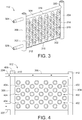
- FIG. 3 A perspective view of an example of a heat transfer plate assembly 112 is shown in FIG. 3 .
- the heat transfer plate assembly 112 includes a heat transfer plate 302, a first fluid conduit 304, a second fluid conduit 306, and a pipe 308.
- the term pipe is utilized herein to refer to a conduit throuch which fluid may flow.
- the pipe 308 is not limited to a cylindrical pipe and may be any other suitable shape to facilitate fluid flow therethrough.
- the heat transfer plate 302 includes a pair of metal sheets 310.
- the sheets 310 may be made from stainless steel, such as 316L stainless steel.
- the two sheets of the pair of sheets 310 are arranged generally parallel to each other.
- the two sheets are welded together at locations on each sheet.
- the two sheets 310 are also seam welded along the bottom edges of the two sheets.
- the sheets are inflated such that generally circular depressions 312 are formed on each sheet.
- the generally circular depressions 312 are distributed throughout each sheet and are located at complementary locations on each sheet such that the depressions 312 on one of the sheets are aligned with the depressions 312 on the other of the sheets.
- spaces are provided between the sheets 310 in areas where the sheets 310 are not welded together.
- the first fluid conduit 304 extends along a first side 314 of the heat transfer plate 302, at least between a top end 316 and a bottom end 318 of the heat transfer plate 302.
- the first fluid conduit 304 is welded to first side edges of each of the sheets 310.
- the second fluid conduit 306 extends along an opposing second side 320 of the heat transfer plate 302, at least between the top end 316 and the bottom end 318 of the heat transfer plate 302.
- the second fluid conduit 306 is welded to opposing second side edges of each of the sheets 310.
- the pipe 308 extends along the top end 316 of the heat transfer plate 302.
- a first end 322 of the pipe 308 is in fluid communication with the first fluid conduit 304.
- the pipe 308 passes through the second fluid conduit 306.
- the pipe 308 may be in fluid communication with a top portion 410 (shown in FIG. 4 ) of the second fluid conduit 306.
- a second end 324 of the pipe 308 extends from second fluid conduit 306 to provide a cooling fluid inlet.
- the pipe 308 is welded to the top edges of each of the sheets 310.
- the pipe 308 may be have a diameter that is slightly less than or equal to the thickness of the heat transfer plate 302 to facilitate the flow of cooling fluid into the heat transfer plate 302, and to facilitate the flow of bulk solids 110 past the heat transfer plate 302.
- top and bottom are utilized herein to provide reference to the orientation of the heat exchanger plate assemblies 112 and the heat exchanger 100 when assembled.
- the heat transfer plate assembly 112 also includes a cooling fluid outlet 326.
- the cooling fluid outlet 326 is located near the bottom end 318 of the heat transfer plate 302.
- the cooling fluid outlet 326 extends substantially perpendicular to and away from the second fluid conduit 306.
- the cooling fluid outlet 326 is in fluid communication with the second fluid conduit 306.
- the first fluid conduit 304 and the second fluid conduit 306 each have a diameter that is larger than the diameter of the pipe 308.
- the diameters of the first and second fluid conduits 304, 306 may be larger than the diameter of the pipe 308 to space apart the heat transfer plates 302 of adjacent heat transfer plate assemblies 112 when the heat transfer plate assemblies 112 are arranged in a bank.
- the diameters of the first and second fluid conduits 304, 306 may be equal to or less than the diameter of the pipe 308.
- the first fluid conduits 304 of one bank of plate assemblies 112 may be aligned with the first fluid conduits 304 of the bank of plate assemblies 112 directly below such that the first fluid conduits 304 of the lower bank of plate assemblies 112 support the first fluid conduits 304 of the upper bank of plate assemblies 112.
- the second fluid conduits 306 of the lower bank of plate assemblies 112 support the second fluid conduits 306 of the upper bank of plate assemblies 112.
- a respective first fluid conduit 304 of each heat transfer plate assembly 112 of the top bank 116 is disposed on a respective first fluid conduit 304 of each heat transfer plate assembly 112 of the intermediate bank 120
- a respective second fluid conduit 306 of each heat transfer plate assembly 112 of the top bank 116 is disposed on a respective second fluid conduit 306 of each heat transfer plate assembly 112 of the intermediate bank 120.
- each heat transfer plate assembly 112 of the intermediate bank 120 is disposed on a respective first fluid conduit 304 of each heat transfer plate assembly 112 of the intermediate bank 122
- a respective second fluid conduit 306 of each heat transfer plate assembly 112 of the intermediate bank 120 is disposed on a respective second fluid conduit 306 of each heat transfer plate assembly 112 of the intermediate bank 122, and so forth.
- the first fluid conduit 304 includes openings 402 into the heat transfer plate 302.
- the openings 402 are distributed along the first fluid conduit 304 at the first side 314 of the heat transfer plate 302.
- the openings 402 may be unevenly distributed such that the openings 402 are more closely spaced near the top of the first fluid conduit 304.
- the openings 402 may be larger near the top of the first fluid conduit 304.
- the second fluid conduit 306 includes openings 404 into the heat transfer plate 302.
- the openings 402 are distributed along the second fluid conduit 306 at the second side 318 of the heat transfer plate 302.
- the openings 404 may be unevenly distributed such that the openings 404 are more closely spaced near the top of the second fluid conduit 306. Alternatively, the openings 404 may be larger near the top of the second fluid conduit 306.
- the pipe 308 also includes an opening 408 to a top portion 410 of the second fluid conduit 306 to provide cooling fluid to the top portion 410 of the second fluid conduit 306.
- the cooling fluid enters the top portion 410 of the second fluid conduit 306 through opening 408.
- the cooling fluid exits the pipe 308 and enters a top portion 412 of the first fluid conduit 304.
- the cooling fluid also enters the first fluid conduit 304.
- the top portion 410 of the second fluid conduit 306 and the top portion 412 of the first fluid conduit 304 may be sized to inhibit overheating of the top portions 410, 412.
- the top portions 410, 412 of the first and second fluid conduits 304, 306 are short enough to facilitate fluid flow and cooling of the top portion 410, 412.
- fluid may flow through the top portions 410, 412 of the first and second fluid conduits 304, 306 to further cool the top portions 410, 412.
- the top portions 410, 412 may be longer and spacing between the banks 116, 118, 120, 122, 124, and 126, that are arranged in a stack 114, may be increased.
- cooling fluid flows from the cooling fluid inlet manifold 132 through the respective fluid lines 136 into the respective pipes 308 of the heat transfer plate assemblies 112 of the top bank 116.
- cooling fluid flows from the cooling fluid inlet manifold 132 through the respective fluid lines 136 into the respective pipes 308 of the heat transfer plate assemblies 112 of the top bank 116.
- the flow of cooling fluid through one of the heat transfer plate assemblies 112 will be described with reference to FIG. 4 .
- the cooling fluid flows through the pipe 308 of the heat transfer plate assembly 112 into the first fluid conduit 304. Cooling fluid also flows from the pipe 308, through the opening 408, and into the portion 309 of the second fluid conduit 306. From the first fluid conduit 304, the cooling fluid flows into the heat transfer plate 112 through the openings 402. The cooling fluid flows through the heat transfer plate 302 into the second fluid conduit 306, through the openings 404 in the second fluid conduit 306. The generally circular depressions 312 distributed throughout the heat transfer plate 302 facilitate the flow of the cooling fluid throughout the heat transfer plate 302. The cooling fluid then flows from the second fluid conduit 306 into the cooling fluid outlet 326.
- the cooling fluid flows from the cooling fluid outlet 324 of each heat transfer plate assemblies 112 of the top bank 116, through the respective fluid lines 140, and into the respective pipes 308 of the heat transfer plate assemblies 112 of the intermediate bank 120.
- the cooling fluid flows through each heat transfer plate assembly 112 of the intermediate bank 120 in a similar manner as described above.
- the cooling fluid then flows from the cooling fluid outlet 326 of each heat transfer plate assemblies 112 of the intermediate bank 120, through the respective fluid lines 142, and into the respective pipes 308 of the heat transfer plate assemblies 112 of the intermediate bank 122.
- the cooling fluid flows through each heat transfer plate assembly 112 of the intermediate bank 122 in a similar manner as described above.
- the cooling fluid then flows from the cooling fluid outlet 326 of the heat transfer plate assemblies 112 of the intermediate bank 124, through the respective fluid lines 144, and into the respective pipes 308 of the heat transfer plate assemblies 112 of the intermediate bank 124.
- the cooling fluid flows through each heat transfer plate assembly 112 of the intermediate bank 124 in a similar manner as described above.
- the cooling fluid flows from the cooling fluid outlet 326 of each heat transfer plate assemblies 112 of the intermediate bank 124, through the respective fluid lines 146, and into the respective pipes 308 of the heat transfer plate assemblies 112 of the intermediate bank 126.
- the cooling fluid flows through each heat transfer plate assembly 112 of the intermediate bank 126 in a similar manner as described above.
- the cooling fluid flows from the cooling fluid outlet 326 of each heat transfer plate assemblies 112 of the intermediate bank 126, through the respective fluid lines 148, and into the respective pipes 308 of the heat transfer plate assemblies 112 of the bottom bank 118.
- the cooling fluid flows through each heat transfer plate assembly 112 of the bottom bank 118 in a similar manner as described above.
- the cooling fluid flows from the cooling fluid outlet 326 of each heat transfer plate assemblies 112 of the bottom bank 118 through the respective fluid lines 138, and into the cooling fluid discharge manifold 134.
- cooling inlet manifold 132 may be a cooling fluid outlet manifold
- cooling fluid inlet manifold 134 may be a cooling fluid outlet manifold
- the direction of flow of cooling fluid through the stack 114 and the heat transfer plates 112 may be in an opposite direction to that described such that the cooling fluid flows upwardly through the stack.
- the operation of the heat exchanger 100 will now be described with reference to FIG. 1 to FIG. 4 .
- the bulk solids 110 When bulk solids 110 are fed into the housing 102, through the inlet 108, the bulk solids 110 flow downwardly as a result of the force of gravity from the inlet 108 into the hopper 128.
- the hopper 128 facilitates distribution of the bulk solids 110 onto to the top bank 116 of the stack 114 of heat transfer plate assemblies 112.
- the bulk solids 110 flow through passageways 206 between adjacent heat transfer plate assemblies 112, to the outlet. Bulk solids 110 that contact the pipes 308 of the heat transfer plates 302 are deflected into the passageways 206.
- the bulk solids 110 flow between adjacent heat transfer plate assemblies 112, through the passageways 206, the bulk solids 110 are cooled as the heat from the bulk solids 110 is transferred to the heat transfer plate assemblies 112 and to the cooling fluid.
- the cooling fluid that flows through the heat transfer plate assemblies 112 indirectly cools bulk solids 110.
- the cooled bulk solids 110 flow from the passageways 206, through the outlet, and into the discharge hopper 130, where the cooled bulk solids 110 are discharged under a "choked" flow.
- each heat transfer plate assembly 112 cools the top end 316 of each heat transfer plate 302, thereby protecting the top end 316 of each heat transfer plate 302 from damage caused by heat that is transferred into the heat transfer plate 302 from the flowing high temperature bulk solids 110.
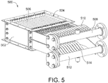
- FIG. 5 A perspective view of a portion of a heat exchanger including a single bank of heat transfer plate assemblies accordance with another embodiment is shown in FIG. 5 .
- the heat exchanger 500 includes a housing 502 with a generally rectangular cross-section.
- a single bank 504 of heat transfer plate assemblies 506 is disposed in the housing 502.
- the heat transfer plate assemblies 506 are similar to the heat transfer plate assemblies 112 described above and are not described again herein.
- a cooling fluid inlet manifold 508 is coupled to the housing 502 and is in fluid communication with each heat transfer plate assembly 506.
- a respective fluid line 510 extends from each heat transfer plate assembly 506 to the cooling fluid inlet manifold 508.
- a cooling fluid discharge manifold 512 is coupled to the housing 502 and is in fluid communication with each heat transfer plate assembly 506.
- a respective fluid line 514 extends from each heat transfer plate assembly 506 to the cooling fluid discharge manifold 512. Operation of the heat exchanger 500 is similar to that described above with reference to FIG. 1 to FIG. 4 .
- the heat exchanger 500 may include multiple banks 504.
- the banks 504 may be disposed in the housing 502 and arranged in a stack.
- a cooling fluid inlet manifold 508 and a cooling fluid discharge manifold 512 may be coupled to each bank 504.
- a respective cooling fluid inlet manifold 504 may be in fluid communication with each heat transfer plate assembly 506 of a respective bank 504.
- a respective fluid line 510 may extend from each heat transfer plate assembly 506 of the respective banks 504 to the respective cooling fluid inlet manifolds 508.
- a respective cooling fluid discharge manifold 512 may be in fluid communication with each heat transfer plate assembly 506 of a respective bank 504.
- a respective fluid line 514 may extend from each heat transfer plate assembly 506 of the respective bans 504 to the respective cooling fluid discharge manifolds 512.
- FIG. 6 and FIG. 7 A perspective view of another example of a heat transfer plate assembly 612 is shown in FIG. 6 and FIG. 7 .
- the heat transfer plate assembly 612 includes a heat transfer plate 602, a first fluid conduit 604, a second fluid conduit
- the pair of metal sheets 610 and the pipe 608 are formed by bending a sheet of metal.
- the pipe 608, that is formed along the top of the metal sheets 610, may be welded along a bottom edge, which is the top edge of the metal sheets 610.
- the pipe 608 is not limited to a cylindrical pipe and may be any other suitable shape to facilitate fluid flow therethrough. In the example illustrated in FIG. 6 , the pipe is not cylindrical.
- the two metal sheets 610 that are formed, are generally parallel to each other and are welded as in the example described above with reference to FIG. 3 .
- the remainder of the features of the assembly of FIG. 6 are similar to those described above with reference to FIG. 3 and are not described again in detail to avoid obscuring the description.
- FIG. 8 a side sectional view of another example of a heat transfer plate assembly 812 is shown.
- the pipe 308 is closed to the top portion 802 of the second fluid conduit 306 such that cooling fluid does not flow from the second end 324 of the pipe 308 into the top portion 802.
- the top portion 802 of the second fluid conduit 306 and the top portion 804 of the first fluid conduit 304 may be very short and the spacing between the banks of heat transfer plate assemblies 812 may be small.
- the size (i.e. the length) of the top portions 802, 804 may be suitably small such that cooling fluid that flows through the pipe 308 cools the top portions 802, 804 to inhibit overheating of the top portions 802, 804.
- heat transfer plate assembly 812 Many of the features and functions of the heat transfer plate assembly 812 are similar to the features and functions of the heat transfer plate assembly 112 described above with reference to FIG. 3 and FIG. 4 and are not described again herein to avoid obscuring the description.
- a side sectional view of still another example of a heat transfer plate assembly 912 is shown.
- a first deflecting baffle 902 is disposed within the first fluid conduit 304 near the first end 322 of the pipe 308.
- a second deflecting baffle 904 is disposed within the second fluid conduit 306 near the second end 324 of the pipe 308.
- the second deflecting baffle 904 extends through an opening 906 in the pipe 308, into a top portion 908 of the second fluid conduit 306.
- the first deflecting baffle 902 diverts cooling fluid, that exits the first end 322 of the pipe 308, into the top portion 910 of the first fluid conduit 304 to facilitate the flow of cooling fluid into the top portion 910 of the first fluid conduit 304. Cooling fluid is diverted into the top portion 910 of the first fluid conduit 304 to increase the flow of cooling fluid into the top portion 910 and to inhibit overheating of the top portion 910.
- the second deflecting baffle 904 diverts cooling fluid, that enters the second end 324 of the pipe 308, into the top portion 908 of the second fluid conduit 306 to facilitate the flow of cooling fluid into the top portion 908 of the second fluid conduit 306. Cooling fluid is diverted into the top portion 908 of the second fluid conduit 306 to increase the flow of cooling fluid into the top portion 908 and to inhibit overheating of the top portion 908.
- the top portions 910 and 908 may be longer and the spacing between the banks of heat transfer plate assemblies 912 may be increased.
- heat transfer plate assembly 912 Many of the features and functions of the heat transfer plate assembly 912 are similar to the features and functions of the heat transfer plate assembly 112 described above with reference to FIG. 3 and FIG. 4 and are not described again herein to avoid obscuring the description.
- the pipe 308 extends along the top end 314 of the heat transfer plates 302 to protect the top end 314 and the first and second sides 312, 318 of each heat transfer plate 302.
- the heat transfer plate includes depressions 312 to facilitate flow of cooling fluid throughout the heat transfer plate 302 during cooling of bulk solids. Operational life of the heat transfer plates 302 may be increased utilizing heat transfer plate assemblies as described.
Landscapes
- Engineering & Computer Science (AREA)
- Physics & Mathematics (AREA)
- Thermal Sciences (AREA)
- Mechanical Engineering (AREA)
- General Engineering & Computer Science (AREA)
- Heat-Exchange Devices With Radiators And Conduit Assemblies (AREA)
Description
- The present disclosure relates to a heat exchanger for cooling bulk solids.
US 2007/256316 discloses a heat exchanger as defined in the preamble of claim 1. - Heat exchangers use indirect cooling plates to cool bulk solids that flow, under the force of gravity, through the heat exchanger. While known heat exchangers may be used to cool bulk solids having temperatures up to 400°C, these heat exchangers are unsuitable for cooling high temperature bulk solids that have temperatures above 400°C. Improvements to heat exchangers are therefore desirable.
- According to the present invention, a heat exchanger as defined in claim 1 has a housing including an inlet for providing bulk solids, and an outlet for discharging the bulk solids, a plurality of spaced apart, substantially parallel heat transfer plate assemblies disposed in the housing between the inlet and the outlet for cooling the bulk solids that flow from the inlet, between adjacent heat transfer plates, to the outlet, ones of the plurality of heat transfer plate assemblies including a heat transfer plate and a pipe extending along an inlet end of the heat transfer plate to protect the heat transfer plate.
- Embodiments of the present invention will be described, by way of example, with reference to the drawings and to the following description, in which:
-
FIG. 1 is a partially cut away perspective view of a heat exchanger for cooling bulk solids in accordance with an embodiment; -
FIG. 2 is a top view of a top bank of heat transfer plate assemblies of the heat exchanger ofFIG. 1 ; -
FIG. 3 is a perspective view of an example of a heat transfer plate assembly of the heat exchanger ofFIG. 1 ; -
FIG. 4 is a sectional side view of the heat transfer plate assembly ofFIG. 3 ; -
FIG. 5 is a perspective view of a portion of a heat exchanger including a single bank of heat transfer plate assemblies in accordance with another embodiment; -
FIG. 6 is a perspective view of another example of a heat transfer plate assembly with a side cut away to show detail; -
FIG. 7 is sectional view of an upper part of the heat transfer plate assembly ofFIG. 6 ; -
FIG. 8 is a sectional side view of another example of a heat transfer plate assembly; -
FIG. 9 is a sectional side view of still another example of a heat transfer plate assembly. - For simplicity and clarity of illustration, reference numerals may be repeated among the figures to indicate corresponding or analogous elements. Numerous details are set forth to provide an understanding of the embodiments described herein. The embodiments may be practiced without these details. In other instances, well-known methods, procedures, and components have not been described in detail to avoid obscuring the embodiments described. The description is not to be considered as limited to the scope of the embodiments described herein.
- The disclosure generally relates to heat exchangers for cooling bulk solids. Examples of bulk solids include metal powders, ash, coke, coals, carbon powders, graphite powders, and other solids that flow under the force of gravity.
- A partially cutaway perspective view of an embodiment of a heat exchanger for cooling bulk solids is shown in
FIG. 1 . Theheat exchanger 100 includes ahousing 102 with a generally rectangular cross-section. Thehousing 102 has atop 104 and abottom 106. Thetop 104 of thehousing 102 includes aninlet 108 for introducingbulk solids 110 into theheat exchanger 100. Thebottom 106 of thehousing 102 is open to provide an outlet (not shown) for discharging cooledbulk solids 110 from thehousing 102 to anoptional discharge hopper 130, and out of theheat exchanger 100. A plurality of heattransfer plate assemblies 112 are disposed within thehousing 102, between theinlet 108 and the outlet. The heattransfer plate assemblies 112 are spaced apart and arranged generally parallel to each other in rows, referred to herein as banks. In the example shown inFIG. 1 , theheat exchanger 100 includes six banks of heattransfer plate assemblies 112. The six banks are arranged in astack 114. Thestack 114 includes atop bank 116, abottom bank 118, and fourintermediate banks transfer plate assemblies 112. Although theheat exchanger 100 ofFIG. 1 includes six banks, other suitable numbers of banks may be utilized. Also, other suitable numbers of heat transfer plate assembles 112 in each bank may be utilized. - The
entire stack 114, including six banks of heattransfer plate assemblies 112 are supported onsupport channels 150 at the bottom of thestack 114. The support channels support the stack and the weight of thebulk solids 110 introduced into theheat exchanger 100 as the weight of the bulk solids is transferred to the heattransfer plate assemblies 112 via friction. - Referring to
FIG.2 , a top view of thetop bank 116 of heattransfer plate assemblies 112 of theheat exchanger 100 ofFIG. 1 is shown. Each heattransfer plate assembly 112 of thetop bank 116 extends the width of thehousing 102 between a first sidewall 202 of thehousing 102 and an opposingsecond sidewall 204 ofhousing 102. The heattransfer plate assemblies 112 are arranged generally parallel to each other with spaces between adjacent heattransfer plate assemblies 112 to providepassageways 206 forbulk solids 110 to flow through. Insulation 205 is disposed between athird sidewall 206 of thehousing 102 and the heattransfer plate assembly 112 located adjacent to thethird sidewall 206, to protect thethird sidewall 206 from wear caused by the flow of thebulk solids 110, by inhibiting bulk solids from flowing into the space between thethird sidewall 206 and the adjacent heattransfer plate assembly 112. Insulation 205 is also disposed between a fourth sidewall 208, and the heattransfer plate assembly 112 located adjacent to thefourth sidewall 206, to protect the fourth sidewall 208 from wear caused by the flow of thebulk solids 110, by inhibiting bulk solids from flowing in the space between the fourth sidewall 208 and the adjacentheat transfer plate 112 assembly. The insulation 205 may be a ceramic fiber sheet of suitable thickness that inhibits the flow ofbulk solids 110 in the spaces between thethird sidewall 206 and the adjacentheat transfer plate 112 assembly, and the fourth sidewall 208 and the adjacentheat transfer plate 112 assembly, respectively. Thebottom bank 118 and the fourintermediate banks top bank 116. - The six
banks transfer plate assemblies 112 may be aligned in columns in thehousing 102 such that thepassageways 206 extend through theentire stack 114. Alternatively, the heat transfer plate assemblies 112 in the sixbanks transfer plate assemblies 112 are offset from one another when the sixbanks housing 102. - Referring again to
FIG. 1 , thetop bank 116 of the stack 114 (i.e. the bank that is located closest to the inlet 108) is sufficiently spaced from theinlet 108 to provide ahopper 128 in thehousing 102 between theinlet 108 and thetop bank 116. Thehopper 128 facilitates distribution ofbulk solids 110 that flow from theinlet 108, as a result of the force of gravity, over the heattransfer plate assemblies 112 of thetop bank 116. The bottom bank 118 (i.e. the bank that is located closest to the outlet of thestack 116 is sufficiently spaced from the outlet) to facilitate the flow ofbulk solids 110 through the outlet. Adischarge hopper 130 may be utilized at the outlet to create a mass flow or "choked flow" of bulk solids and to regulate the flow rate of thebulk solids 110 through theheat exchanger 100. An example of adischarge hopper 130 is described inU.S. Patent 5,167,274 . The term "choked flow" is utilized herein to refer to a flow other than a free fall of thebulk solids 110 as a result of the force of gravity. - The
heat exchanger 100 also includes a coolingfluid inlet manifold 132 and coolingfluid discharge manifold 134. The coolingfluid inlet manifold 132 is coupled to thehousing 102 and is in fluid communication with each heattransfer plate assembly 112 of thetop bank 116 of thestack 114. Arespective fluid line 136 extends from each heattransfer plate assembly 112 of thetop bank 116 to the coolingfluid inlet manifold 132. The coolingfluid discharge manifold 134 is coupled to thehousing 102 and is in fluid communication with each heattransfer plate assembly 112 of thebottom bank 118 of thestack 114. Arespective fluid line 138 extends from each heattransfer plate assembly 112 of thebottom bank 118 to the coolingfluid inlet manifold 134. - In the example of
FIG. 1 , the heat transfer plate assemblies 112 of thetop bank 116, thebottom bank 118, and the fourintermediate banks respective fluid line 140 extends from each heattransfer plate assembly 112 of thetop bank 116 to a respective heattransfer plate assembly 112 of theintermediate bank 120 of the same column. A respective fluid line 142 extends from each heattransfer plate assembly 112 of theintermediate bank 120 to a respective heattransfer plate assembly 112 of theintermediate bank 122 of the same column. Arespective fluid line 144 extends from each heattransfer plate assembly 112 of theintermediate bank 122 to a respective heattransfer plate assembly 112 of theintermediate bank 124 of the same column. Arespective fluid line 146 extends from each heattransfer plate assembly 112 of theintermediate bank 124 to a respective heattransfer plate assembly 112 of theintermediate bank 126 of the same column. Arespective fluid line 148 extends from each heattransfer plate assembly 112 of theintermediate bank 126 to a respective heattransfer plate assembly 112 of thebottom bank 118 of the same column. - A perspective view of an example of a heat
transfer plate assembly 112 is shown inFIG. 3 . The heattransfer plate assembly 112 includes aheat transfer plate 302, a firstfluid conduit 304, a secondfluid conduit 306, and apipe 308. The term pipe is utilized herein to refer to a conduit throuch which fluid may flow. Thepipe 308 is not limited to a cylindrical pipe and may be any other suitable shape to facilitate fluid flow therethrough. - The
heat transfer plate 302 includes a pair ofmetal sheets 310. Thesheets 310 may be made from stainless steel, such as 316L stainless steel. The two sheets of the pair ofsheets 310 are arranged generally parallel to each other. The two sheets are welded together at locations on each sheet. The twosheets 310 are also seam welded along the bottom edges of the two sheets. After the twosheets 310 are welded together, the sheets are inflated such that generallycircular depressions 312 are formed on each sheet. The generallycircular depressions 312 are distributed throughout each sheet and are located at complementary locations on each sheet such that thedepressions 312 on one of the sheets are aligned with thedepressions 312 on the other of the sheets. When thesheets 310 are inflated, spaces are provided between thesheets 310 in areas where thesheets 310 are not welded together. - The first
fluid conduit 304 extends along afirst side 314 of theheat transfer plate 302, at least between atop end 316 and abottom end 318 of theheat transfer plate 302. The firstfluid conduit 304 is welded to first side edges of each of thesheets 310. The secondfluid conduit 306 extends along an opposingsecond side 320 of theheat transfer plate 302, at least between thetop end 316 and thebottom end 318 of theheat transfer plate 302. The secondfluid conduit 306 is welded to opposing second side edges of each of thesheets 310. - The
pipe 308 extends along thetop end 316 of theheat transfer plate 302. Afirst end 322 of thepipe 308 is in fluid communication with the firstfluid conduit 304. Thepipe 308 passes through the secondfluid conduit 306. Thepipe 308 may be in fluid communication with a top portion 410 (shown inFIG. 4 ) of the secondfluid conduit 306. Asecond end 324 of thepipe 308 extends from secondfluid conduit 306 to provide a cooling fluid inlet. Thepipe 308 is welded to the top edges of each of thesheets 310. Thepipe 308 may be have a diameter that is slightly less than or equal to the thickness of theheat transfer plate 302 to facilitate the flow of cooling fluid into theheat transfer plate 302, and to facilitate the flow ofbulk solids 110 past theheat transfer plate 302. - The terms top and bottom are utilized herein to provide reference to the orientation of the heat
exchanger plate assemblies 112 and theheat exchanger 100 when assembled. - Referring again to
FIG. 3 , the heattransfer plate assembly 112 also includes a coolingfluid outlet 326. The coolingfluid outlet 326 is located near thebottom end 318 of theheat transfer plate 302. The coolingfluid outlet 326 extends substantially perpendicular to and away from the secondfluid conduit 306. The coolingfluid outlet 326 is in fluid communication with the secondfluid conduit 306. - The first
fluid conduit 304 and the secondfluid conduit 306 each have a diameter that is larger than the diameter of thepipe 308. When the heattransfer plate assemblies 112 are arranged in a bank, the firstfluid conduits 304 and the secondfluid conduits 306 of adjacentheat transfer assemblies 112 abut each other, as shown inFIG. 2 . The diameters of the first and secondfluid conduits pipe 308 to space apart theheat transfer plates 302 of adjacent heattransfer plate assemblies 112 when the heattransfer plate assemblies 112 are arranged in a bank. Alternatively, the diameters of the first and secondfluid conduits pipe 308. - When the six
banks transfer plate assemblies 112 are arranged in astack 114, the firstfluid conduits 304 of one bank ofplate assemblies 112 may be aligned with the firstfluid conduits 304 of the bank ofplate assemblies 112 directly below such that the firstfluid conduits 304 of the lower bank ofplate assemblies 112 support the firstfluid conduits 304 of the upper bank ofplate assemblies 112. Similarly, the secondfluid conduits 306 of the lower bank ofplate assemblies 112 support the secondfluid conduits 306 of the upper bank ofplate assemblies 112. Thus, a respective firstfluid conduit 304 of each heattransfer plate assembly 112 of thetop bank 116 is disposed on a respective firstfluid conduit 304 of each heattransfer plate assembly 112 of theintermediate bank 120, and a respective secondfluid conduit 306 of each heattransfer plate assembly 112 of thetop bank 116 is disposed on a respective secondfluid conduit 306 of each heattransfer plate assembly 112 of theintermediate bank 120. Similarly, a respective firstfluid conduit 304 of each heattransfer plate assembly 112 of theintermediate bank 120 is disposed on a respective firstfluid conduit 304 of each heattransfer plate assembly 112 of theintermediate bank 122, and a respective secondfluid conduit 306 of each heattransfer plate assembly 112 of theintermediate bank 120 is disposed on a respective secondfluid conduit 306 of each heattransfer plate assembly 112 of theintermediate bank 122, and so forth. - Referring to
FIG. 4 , a side sectional view of the heattransfer plate assembly 112 ofFIG. 3 is shown. The firstfluid conduit 304 includesopenings 402 into theheat transfer plate 302. Theopenings 402 are distributed along the firstfluid conduit 304 at thefirst side 314 of theheat transfer plate 302. Theopenings 402 may be unevenly distributed such that theopenings 402 are more closely spaced near the top of the firstfluid conduit 304. Alternatively, theopenings 402 may be larger near the top of the firstfluid conduit 304. The secondfluid conduit 306 includesopenings 404 into theheat transfer plate 302. Theopenings 402 are distributed along the secondfluid conduit 306 at thesecond side 318 of theheat transfer plate 302. Theopenings 404 may be unevenly distributed such that theopenings 404 are more closely spaced near the top of the secondfluid conduit 306. Alternatively, theopenings 404 may be larger near the top of the secondfluid conduit 306. Thepipe 308 also includes anopening 408 to atop portion 410 of the secondfluid conduit 306 to provide cooling fluid to thetop portion 410 of the secondfluid conduit 306. - The cooling fluid enters the
top portion 410 of the secondfluid conduit 306 throughopening 408. The cooling fluid exits thepipe 308 and enters atop portion 412 of the firstfluid conduit 304. The cooling fluid also enters the firstfluid conduit 304. Thetop portion 410 of the secondfluid conduit 306 and thetop portion 412 of the firstfluid conduit 304 may be sized to inhibit overheating of thetop portions top portions fluid conduits top portion top portions fluid conduits top portions top portions banks stack 114, may be increased. - The flow of cooling fluid through the
stack 114 of heattransfer plate assemblies 112 will now be described with reference toFIG. 1 andFIG. 4 . The flow of the cooling fluid through a heattransfer plate assembly 112 is illustrated by the arrows inFIG. 4 . In operation, cooling fluid flows from the coolingfluid inlet manifold 132 through therespective fluid lines 136 into therespective pipes 308 of the heattransfer plate assemblies 112 of thetop bank 116. For the purposes of this example, the flow of cooling fluid through one of the heattransfer plate assemblies 112 will be described with reference toFIG. 4 . - Referring to
FIG. 4 , the cooling fluid flows through thepipe 308 of the heattransfer plate assembly 112 into the firstfluid conduit 304. Cooling fluid also flows from thepipe 308, through theopening 408, and into the portion 309 of the secondfluid conduit 306. From the firstfluid conduit 304, the cooling fluid flows into theheat transfer plate 112 through theopenings 402. The cooling fluid flows through theheat transfer plate 302 into the secondfluid conduit 306, through theopenings 404 in the secondfluid conduit 306. The generallycircular depressions 312 distributed throughout theheat transfer plate 302 facilitate the flow of the cooling fluid throughout theheat transfer plate 302. The cooling fluid then flows from the secondfluid conduit 306 into the coolingfluid outlet 326. - Referring again to
FIG. 1 , the cooling fluid flows from the coolingfluid outlet 324 of each heattransfer plate assemblies 112 of thetop bank 116, through therespective fluid lines 140, and into therespective pipes 308 of the heattransfer plate assemblies 112 of theintermediate bank 120. The cooling fluid flows through each heattransfer plate assembly 112 of theintermediate bank 120 in a similar manner as described above. - The cooling fluid then flows from the cooling
fluid outlet 326 of each heattransfer plate assemblies 112 of theintermediate bank 120, through the respective fluid lines 142, and into therespective pipes 308 of the heattransfer plate assemblies 112 of theintermediate bank 122. The cooling fluid flows through each heattransfer plate assembly 112 of theintermediate bank 122 in a similar manner as described above. - The cooling fluid then flows from the cooling
fluid outlet 326 of the heattransfer plate assemblies 112 of theintermediate bank 124, through therespective fluid lines 144, and into therespective pipes 308 of the heattransfer plate assemblies 112 of theintermediate bank 124. The cooling fluid flows through each heattransfer plate assembly 112 of theintermediate bank 124 in a similar manner as described above. - The cooling fluid the flows from the cooling
fluid outlet 326 of each heattransfer plate assemblies 112 of theintermediate bank 124, through therespective fluid lines 146, and into therespective pipes 308 of the heattransfer plate assemblies 112 of theintermediate bank 126. The cooling fluid flows through each heattransfer plate assembly 112 of theintermediate bank 126 in a similar manner as described above. - The cooling fluid flows from the cooling
fluid outlet 326 of each heattransfer plate assemblies 112 of theintermediate bank 126, through therespective fluid lines 148, and into therespective pipes 308 of the heattransfer plate assemblies 112 of thebottom bank 118. The cooling fluid flows through each heattransfer plate assembly 112 of thebottom bank 118 in a similar manner as described above. The cooling fluid flows from the coolingfluid outlet 326 of each heattransfer plate assemblies 112 of thebottom bank 118 through therespective fluid lines 138, and into the coolingfluid discharge manifold 134. - Although the flow of cooling fluid has be described herein as flowing in a downward direction through the
stack 114, in an alternative embodiment the coolinginlet manifold 132 may be a cooling fluid outlet manifold, the coolingfluid inlet manifold 134 may be a cooling fluid outlet manifold, and the direction of flow of cooling fluid through thestack 114 and theheat transfer plates 112 may be in an opposite direction to that described such that the cooling fluid flows upwardly through the stack. - The operation of the
heat exchanger 100 will now be described with reference toFIG. 1 to FIG. 4 . Whenbulk solids 110 are fed into thehousing 102, through theinlet 108, thebulk solids 110 flow downwardly as a result of the force of gravity from theinlet 108 into thehopper 128. Thehopper 128 facilitates distribution of thebulk solids 110 onto to thetop bank 116 of thestack 114 of heattransfer plate assemblies 112. Thebulk solids 110 flow throughpassageways 206 between adjacent heattransfer plate assemblies 112, to the outlet.Bulk solids 110 that contact thepipes 308 of theheat transfer plates 302 are deflected into thepassageways 206. - As the
bulk solids 110 flow between adjacent heattransfer plate assemblies 112, through thepassageways 206, thebulk solids 110 are cooled as the heat from thebulk solids 110 is transferred to the heattransfer plate assemblies 112 and to the cooling fluid. The cooling fluid that flows through the heattransfer plate assemblies 112 indirectly coolsbulk solids 110. The cooledbulk solids 110 flow from thepassageways 206, through the outlet, and into thedischarge hopper 130, where the cooledbulk solids 110 are discharged under a "choked" flow. The flow of cooling fluid through thepipe 308 of each heattransfer plate assembly 112 cools thetop end 316 of eachheat transfer plate 302, thereby protecting thetop end 316 of eachheat transfer plate 302 from damage caused by heat that is transferred into theheat transfer plate 302 from the flowing hightemperature bulk solids 110. - A perspective view of a portion of a heat exchanger including a single bank of heat transfer plate assemblies accordance with another embodiment is shown in
FIG. 5 . Theheat exchanger 500 includes ahousing 502 with a generally rectangular cross-section. Asingle bank 504 of heattransfer plate assemblies 506 is disposed in thehousing 502. The heattransfer plate assemblies 506 are similar to the heattransfer plate assemblies 112 described above and are not described again herein. - A cooling
fluid inlet manifold 508 is coupled to thehousing 502 and is in fluid communication with each heattransfer plate assembly 506. Arespective fluid line 510 extends from each heattransfer plate assembly 506 to the coolingfluid inlet manifold 508. A coolingfluid discharge manifold 512 is coupled to thehousing 502 and is in fluid communication with each heattransfer plate assembly 506. Arespective fluid line 514 extends from each heattransfer plate assembly 506 to the coolingfluid discharge manifold 512. Operation of theheat exchanger 500 is similar to that described above with reference toFIG. 1 to FIG. 4 . - Although the embodiment described herein with reference to
FIG. 5 includes asingle bank 504 of heattransfer plate assemblies 506, in an alternative embodiment, theheat exchanger 500 may includemultiple banks 504. Thebanks 504 may be disposed in thehousing 502 and arranged in a stack. A coolingfluid inlet manifold 508 and a coolingfluid discharge manifold 512 may be coupled to eachbank 504. A respective coolingfluid inlet manifold 504 may be in fluid communication with each heattransfer plate assembly 506 of arespective bank 504. Arespective fluid line 510 may extend from each heattransfer plate assembly 506 of therespective banks 504 to the respective cooling fluid inlet manifolds 508. A respective coolingfluid discharge manifold 512 may be in fluid communication with each heattransfer plate assembly 506 of arespective bank 504. Arespective fluid line 514 may extend from each heattransfer plate assembly 506 of therespective bans 504 to the respective cooling fluid discharge manifolds 512. - A perspective view of another example of a heat
transfer plate assembly 612 is shown inFIG. 6 and FIG. 7 . The heattransfer plate assembly 612 includes aheat transfer plate 602, a firstfluid conduit 604, a second fluid conduit - (not shown), and a
pipe 608. A side of the heat transfer plate assembly, including the second fluid conduit, is cut away to show detail. - In the example illustrated in
FIG. 6 and FIG. 7 , the pair ofmetal sheets 610 and thepipe 608 are formed by bending a sheet of metal. Thepipe 608, that is formed along the top of themetal sheets 610, may be welded along a bottom edge, which is the top edge of themetal sheets 610. As indicated above, thepipe 608 is not limited to a cylindrical pipe and may be any other suitable shape to facilitate fluid flow therethrough. In the example illustrated inFIG. 6 , the pipe is not cylindrical. - The two
metal sheets 610 that are formed, are generally parallel to each other and are welded as in the example described above with reference toFIG. 3 . The remainder of the features of the assembly ofFIG. 6 are similar to those described above with reference toFIG. 3 and are not described again in detail to avoid obscuring the description. - Referring to
FIG. 8 , a side sectional view of another example of a heattransfer plate assembly 812 is shown. In this example, thepipe 308 is closed to thetop portion 802 of the secondfluid conduit 306 such that cooling fluid does not flow from thesecond end 324 of thepipe 308 into thetop portion 802. Thetop portion 802 of the secondfluid conduit 306 and thetop portion 804 of the firstfluid conduit 304 may be very short and the spacing between the banks of heattransfer plate assemblies 812 may be small. The size (i.e. the length) of thetop portions pipe 308 cools thetop portions top portions - Many of the features and functions of the heat
transfer plate assembly 812 are similar to the features and functions of the heattransfer plate assembly 112 described above with reference toFIG. 3 and FIG. 4 and are not described again herein to avoid obscuring the description. - Referring to
FIG. 9 , a side sectional view of still another example of a heattransfer plate assembly 912 is shown. In this example, afirst deflecting baffle 902 is disposed within the firstfluid conduit 304 near thefirst end 322 of thepipe 308. Asecond deflecting baffle 904 is disposed within the secondfluid conduit 306 near thesecond end 324 of thepipe 308. Thesecond deflecting baffle 904 extends through anopening 906 in thepipe 308, into atop portion 908 of the secondfluid conduit 306. Thefirst deflecting baffle 902 diverts cooling fluid, that exits thefirst end 322 of thepipe 308, into thetop portion 910 of the firstfluid conduit 304 to facilitate the flow of cooling fluid into thetop portion 910 of the firstfluid conduit 304. Cooling fluid is diverted into thetop portion 910 of the firstfluid conduit 304 to increase the flow of cooling fluid into thetop portion 910 and to inhibit overheating of thetop portion 910. - The
second deflecting baffle 904 diverts cooling fluid, that enters thesecond end 324 of thepipe 308, into thetop portion 908 of the secondfluid conduit 306 to facilitate the flow of cooling fluid into thetop portion 908 of the secondfluid conduit 306. Cooling fluid is diverted into thetop portion 908 of the secondfluid conduit 306 to increase the flow of cooling fluid into thetop portion 908 and to inhibit overheating of thetop portion 908. - By including deflection baffles 902, 904 within the first and second
fluid conduits top portions transfer plate assemblies 912 may be increased. - Many of the features and functions of the heat
transfer plate assembly 912 are similar to the features and functions of the heattransfer plate assembly 112 described above with reference toFIG. 3 and FIG. 4 and are not described again herein to avoid obscuring the description. - Advantageously, the
pipe 308 extends along thetop end 314 of theheat transfer plates 302 to protect thetop end 314 and the first andsecond sides heat transfer plate 302. The heat transfer plate includesdepressions 312 to facilitate flow of cooling fluid throughout theheat transfer plate 302 during cooling of bulk solids. Operational life of theheat transfer plates 302 may be increased utilizing heat transfer plate assemblies as described. - The described embodiments are to be considered in all respects only as illustrative and not restrictive. All changes that come with meaning and range of equivalency of the claims are to be embraced within their scope.
Claims (15)
- A heat exchanger (100, 500) comprising:a housing (102, 502) including an inlet (108) for receiving bulk solids, and an outlet for discharging the bulk solids;a plurality of spaced apart, substantially parallel heat transfer plate assemblies (112, 506, 612, 812, 912) disposed in the housing (102, 502) between the inlet (108) and the outlet for cooling the bulk solids that flow from the inlet (108), between adjacent heat transfer plate assemblies (112, 506, 612, 812, 912), to the outlet;ones of the plurality of heat transfer plate assemblies (112, 506, 612, 812, 912) including a heat transfer plate (302, 602),characterized by a pipe (308, 608) extending along a top end (316) of the heat transfer plate (302, 602) to protect the heat transfer plate (302, 602).
- The heat exchanger (100, 500) according to claim 1, wherein the ones of the plurality of heat transfer plate assemblies (112, 506, 612, 812, 912) include a first fluid conduit (304, 604) extending along a first side of the heat transfer plate (302, 602) and a second fluid conduit (306) extending along a second side of the heat transfer plate (302, 602).
- The heat exchanger (100, 500) according to claim 2, wherein the first fluid conduit (304, 604) and the second fluid conduit (306) each have a diameter that is greater than a diameter of the pipe (308, 608) and a thickness of the heat transfer plate (302, 602).
- The heat exchanger (100, 500) according to claim 3, wherein the first fluid conduits (304, 604) abut one another and the second fluid conduits (306) abut one another such that adjacent heat transfer plate assemblies (112, 506, 612, 812, 912) are spaced apart by the first fluid conduit (304, 604) and the second fluid conduit (306).
- The heat exchanger (100, 500) according to claim 3, wherein a first end (322) of the pipe (308, 608) is in fluid communication with the first fluid conduit (304, 604).
- The heat exchanger (100, 500) according to claim 5, wherein the first fluid conduit (304, 604) is in fluid communication with the heat transfer plate (302, 602) along the first side (314) of the heat transfer plate (302, 602) and the second fluid conduit (306) is in fluid communication with the heat transfer plate (302, 602) along the second side (320) of the heat transfer plate (302, 602).
- The heat exchanger (100, 500) according to claim 6, wherein the first fluid conduit (304, 604) includes first openings (402) unevenly distributed along the first side (314) of the heat transfer plate (302, 602) such that the first openings (402) are more closely spaced near a top end (412) of the first fluid conduit (304, 604).
- The heat exchanger (100, 500) according to claim 6, wherein the first fluid conduit (304, 604) includes first openings (402) distributed along the first side (314) of the heat transfer plate (302, 602), wherein ones of the first openings (402) located near the top end (412) of the first fluid conduit (304, 604) are larger than ones of the first openings (402) located near a bottom end of the first fluid conduit (304, 604).
- The heat exchanger (100, 500) according to claim 7, wherein the second fluid conduit (306) includes second openings (404) unevenly distributed along the second side (320) of the heat transfer plate (302, 602) such that the second openings (404) are more closely spaced near a top end (410, 804, 910) of the second fluid conduit (306).
- The heat exchanger (100, 500) according to claim 8, wherein the second fluid conduit (306) includes second openings (404) distributed along the second side (320) of the heat transfer plate (302, 602), wherein ones of the second openings (404) located near the top end (410, 804, 910) of the second fluid conduit (306) are larger than ones of the second openings (404) located near a bottom end of the second fluid conduit (306).
- The heat exchanger (100, 500) according to claim 6, wherein the pipe (308, 608) is in fluid communication with a top end (410, 804, 910) of the second fluid conduit (306) by a third opening (408) in the top end of the second fluid conduit (306) to provide cooling fluid to the top end (410, 804, 910) of the second fluid conduit (306).
- The heat exchanger (100, 500) according to claim 1, comprising insulation (205) disposed between the plurality of heat transfer plate assemblies (112, 506, 612, 812, 912) and a sidewall (206) of the housing (102, 502) to protect the sidewall (206).
- The heat exchanger (100, 500) according to claim 1, wherein the pipe (308, 608) is formed on the top end (316) of the heat transfer plate (302, 602).
- The heat exchanger (100, 500) according to claim 1, wherein the heat transfer plate (302, 602) comprises a pair of metal sheets (310, 610) welded together to facilitate fluid flow therethrough and wherein the pair of metal sheets (310, 610) and the pipe (308, 608) are formed from a single sheet of metal.
- The heat exchanger (100, 500) according to claim 6, wherein the first fluid conduit (304, 604) comprises a first deflecting baffle (902) to provide cooling fluid into an end of the first fluid conduit (304, 604).
Applications Claiming Priority (2)
| Application Number | Priority Date | Filing Date | Title |
|---|---|---|---|
| US13/464,793 US9459054B2 (en) | 2012-05-04 | 2012-05-04 | Heat exchanger for cooling bulk solids |
| PCT/CA2013/050298 WO2013163752A1 (en) | 2012-05-04 | 2013-04-18 | Heat exchanger for cooling bulk solids |
Publications (3)
| Publication Number | Publication Date |
|---|---|
| EP2864730A1 EP2864730A1 (en) | 2015-04-29 |
| EP2864730A4 EP2864730A4 (en) | 2015-10-07 |
| EP2864730B1 true EP2864730B1 (en) | 2018-03-28 |
Family
ID=49511661
Family Applications (1)
| Application Number | Title | Priority Date | Filing Date |
|---|---|---|---|
| EP13784266.2A Active EP2864730B1 (en) | 2012-05-04 | 2013-04-18 | Heat exchanger for cooling bulk solids |
Country Status (4)
| Country | Link |
|---|---|
| US (1) | US9459054B2 (en) |
| EP (1) | EP2864730B1 (en) |
| CA (1) | CA2872058C (en) |
| WO (1) | WO2013163752A1 (en) |
Families Citing this family (12)
| Publication number | Priority date | Publication date | Assignee | Title |
|---|---|---|---|---|
| US9562194B2 (en) | 2014-02-11 | 2017-02-07 | Solex Thermal Science Inc. | Torrefaction reactor |
| US9638478B2 (en) * | 2014-07-25 | 2017-05-02 | Solex Thermal Science Inc. | Heat exchanger for cooling bulk solids |
| EP2995898A3 (en) * | 2014-09-12 | 2016-05-11 | Solex Thermal Science Inc. | Heat exchanger for heating bulk solids |
| WO2017024374A1 (en) * | 2015-08-13 | 2017-02-16 | Solex Thermal Science Inc. | Indirect-heat thermal processing of bulk solids |
| US9683781B2 (en) * | 2015-08-13 | 2017-06-20 | Solex Thermal Science Inc. | Indirect-heat thermal processing of bulk solids |
| PL3285036T3 (en) | 2016-08-14 | 2021-07-05 | Dallmann Engineering & Service | HEAT EXCHANGER MODULE FOR SOLIDS |
| MY206995A (en) * | 2017-01-24 | 2025-01-23 | Crown Iron Works Co | Modular vertical seed conditioner heating section |
| EP3724588A4 (en) * | 2017-12-14 | 2021-12-15 | Solex Energy Science Inc. | HEATING OR COOLING PLATE HEAT EXCHANGER FOR BULK SOLIDS |
| CZ201873A3 (en) * | 2018-02-14 | 2019-05-15 | Farmet A.S. | Loose material heater |
| CN108441237A (en) * | 2018-03-21 | 2018-08-24 | 包头钢铁(集团)有限责任公司 | Coke powder cooling device |
| EP4105479B1 (en) | 2021-06-15 | 2025-05-14 | John Cockerill Renewables S.A. | Particle heat exchanger for a solar tower power plant |
| CN116242188A (en) * | 2022-04-09 | 2023-06-09 | 浙江师范大学 | Three-dimensional hollow heat exchanger and its supercooled water preparation system |
Family Cites Families (19)
| Publication number | Priority date | Publication date | Assignee | Title |
|---|---|---|---|---|
| US3397460A (en) | 1965-10-12 | 1968-08-20 | Internat Processes Ltd | Heat exchange system for calciner |
| US4253520A (en) * | 1978-10-26 | 1981-03-03 | The Garrett Corporation | Heat exchanger construction |
| US4292743A (en) | 1979-11-27 | 1981-10-06 | Razus Virgiliu T | Cereal dryer |
| US4424634A (en) | 1981-06-19 | 1984-01-10 | Westelaken C | Modular column dryer for particulate material |
| DE3317204C1 (en) | 1982-05-08 | 1984-10-31 | Zippe Gmbh U. Co, 6980 Wertheim | Device for preheating glass fragments or similar loose materials |
| DE3507203C1 (en) | 1985-03-01 | 1986-06-12 | DEC Engineering GmbH, 4650 Gelsenkirchen | Device for cleaning plate heat exchangers for the heat recovery of exhaust air |
| US5167274A (en) * | 1988-08-26 | 1992-12-01 | Cominco Ltd. | Method and apparatus for cooling particulate solids |
| US5884416A (en) | 1996-07-11 | 1999-03-23 | Crown Iron Works Company | Grain dryer module |
| US6328099B1 (en) | 1999-04-21 | 2001-12-11 | Mississippi Chemical Corporation | Moving bed dryer |
| JP3865030B2 (en) | 1999-08-04 | 2007-01-10 | 金子農機株式会社 | Grain drying equipment |
| AUPR590101A0 (en) | 2001-06-25 | 2001-07-19 | Jott Australia Pty. Ltd. | Fluid/solid interaction apparatus |
| US20030159816A1 (en) * | 2002-02-22 | 2003-08-28 | Valeo Inc. | Heat exchanger apparatus with integrated supply/return tube |
| JP3911604B2 (en) * | 2002-03-12 | 2007-05-09 | 株式会社日立製作所 | Heat exchanger and refrigeration cycle |
| US7506683B2 (en) * | 2004-05-21 | 2009-03-24 | Valeo, Inc. | Multi-type fins for multi-exchangers |
| GB2422004A (en) | 2005-01-07 | 2006-07-12 | Hiflux Ltd | Plate heat exchanger |
| US7143822B2 (en) * | 2005-03-18 | 2006-12-05 | Denso International America, Inc. | Variable oil cooler tube size for combo cooler |
| NL1028777C2 (en) | 2005-04-15 | 2006-10-17 | Omega Engineering Holding B V | Method for manufacturing a hollow panel and panel obtained with the method. |
| EP1788335A1 (en) * | 2005-11-18 | 2007-05-23 | Methanol Casale S.A. | Method for the production of a plate type heat exchanger and related heat exchanger |
| US8578624B2 (en) | 2006-05-05 | 2013-11-12 | Solex Thermal Science Inc. | Indirect-heat thermal processing of particulate material |
-
2012
- 2012-05-04 US US13/464,793 patent/US9459054B2/en active Active
-
2013
- 2013-04-18 CA CA2872058A patent/CA2872058C/en active Active
- 2013-04-18 WO PCT/CA2013/050298 patent/WO2013163752A1/en not_active Ceased
- 2013-04-18 EP EP13784266.2A patent/EP2864730B1/en active Active
Non-Patent Citations (1)
| Title |
|---|
| None * |
Also Published As
| Publication number | Publication date |
|---|---|
| CA2872058C (en) | 2019-07-09 |
| US20130292093A1 (en) | 2013-11-07 |
| US9459054B2 (en) | 2016-10-04 |
| CA2872058A1 (en) | 2013-11-07 |
| EP2864730A4 (en) | 2015-10-07 |
| EP2864730A1 (en) | 2015-04-29 |
| WO2013163752A1 (en) | 2013-11-07 |
Similar Documents
| Publication | Publication Date | Title |
|---|---|---|
| CA2872058C (en) | Heat exchanger for cooling bulk solids | |
| US20180347918A1 (en) | Heat exchanger for cooling or heating bulk solids | |
| US9638478B2 (en) | Heat exchanger for cooling bulk solids | |
| EP2995898A2 (en) | Heat exchanger for heating bulk solids | |
| US20040086765A1 (en) | Fuel cell insulating heat exchanger | |
| EP2527775A1 (en) | Heat transfer plate for a plate-and-shell heat exchanger | |
| EP1532414B1 (en) | Multiservice heat exchange unit | |
| CN101443107A (en) | Isothermal reactor | |
| KR20150051910A (en) | Apparatus comprising a fuel cell unit and a component, a component unit and a stack component for use in such an apparatus | |
| WO2019000079A1 (en) | Heat exchanger for heating or cooling bulk solids | |
| US20100173209A1 (en) | Fuel cell two-phase coolant exit manifold | |
| CA2857852A1 (en) | Heat exchanger for cooling bulk solids | |
| KR20030093098A (en) | Heat exchanger | |
| US20070295479A1 (en) | Plate-type heat exchanger | |
| CA2851781A1 (en) | Heat exchanger for cooling or heating bulk solids | |
| CA2995270C (en) | Indirect-heat thermal processing of bulk solids | |
| US9683781B2 (en) | Indirect-heat thermal processing of bulk solids | |
| CN209043091U (en) | Granular solids cooler | |
| US8833436B2 (en) | Heat exchange assembly exchanging heat between a first and a second fluid | |
| US11959708B2 (en) | Plate heat exchanger for heating or cooling bulk solids | |
| US7754163B2 (en) | Pseudo-isothermal catalytic reactor | |
| EP4220060B1 (en) | Heat exchanger unit and method for fluid to passively bypassing a heat exchanger | |
| CN119554554B (en) | A method and device for heating a hydrogen storage container | |
| EP3037766B1 (en) | Heat exchanger | |
| CN111093818A (en) | Chemical reactor with adiabatic catalytic bed and axial flow |
Legal Events
| Date | Code | Title | Description |
|---|---|---|---|
| PUAI | Public reference made under article 153(3) epc to a published international application that has entered the european phase |
Free format text: ORIGINAL CODE: 0009012 |
|
| 17P | Request for examination filed |
Effective date: 20141125 |
|
| AK | Designated contracting states |
Kind code of ref document: A1 Designated state(s): AL AT BE BG CH CY CZ DE DK EE ES FI FR GB GR HR HU IE IS IT LI LT LU LV MC MK MT NL NO PL PT RO RS SE SI SK SM TR |
|
| AX | Request for extension of the european patent |
Extension state: BA ME |
|
| DAX | Request for extension of the european patent (deleted) | ||
| RA4 | Supplementary search report drawn up and despatched (corrected) |
Effective date: 20150908 |
|
| RIC1 | Information provided on ipc code assigned before grant |
Ipc: F28F 3/12 20060101AFI20150902BHEP Ipc: F28D 1/03 20060101ALI20150902BHEP Ipc: F28D 1/06 20060101ALI20150902BHEP Ipc: F28F 9/26 20060101ALI20150902BHEP |
|
| GRAP | Despatch of communication of intention to grant a patent |
Free format text: ORIGINAL CODE: EPIDOSNIGR1 |
|
| INTG | Intention to grant announced |
Effective date: 20171010 |
|
| GRAS | Grant fee paid |
Free format text: ORIGINAL CODE: EPIDOSNIGR3 |
|
| GRAA | (expected) grant |
Free format text: ORIGINAL CODE: 0009210 |
|
| AK | Designated contracting states |
Kind code of ref document: B1 Designated state(s): AL AT BE BG CH CY CZ DE DK EE ES FI FR GB GR HR HU IE IS IT LI LT LU LV MC MK MT NL NO PL PT RO RS SE SI SK SM TR |
|
| REG | Reference to a national code |
Ref country code: GB Ref legal event code: FG4D |
|
| REG | Reference to a national code |
Ref country code: CH Ref legal event code: EP |
|
| REG | Reference to a national code |
Ref country code: AT Ref legal event code: REF Ref document number: 983825 Country of ref document: AT Kind code of ref document: T Effective date: 20180415 |
|
| REG | Reference to a national code |
Ref country code: IE Ref legal event code: FG4D |
|
| REG | Reference to a national code |
Ref country code: DE Ref legal event code: R096 Ref document number: 602013035120 Country of ref document: DE |
|
| PG25 | Lapsed in a contracting state [announced via postgrant information from national office to epo] |
Ref country code: FI Free format text: LAPSE BECAUSE OF FAILURE TO SUBMIT A TRANSLATION OF THE DESCRIPTION OR TO PAY THE FEE WITHIN THE PRESCRIBED TIME-LIMIT Effective date: 20180328 Ref country code: LT Free format text: LAPSE BECAUSE OF FAILURE TO SUBMIT A TRANSLATION OF THE DESCRIPTION OR TO PAY THE FEE WITHIN THE PRESCRIBED TIME-LIMIT Effective date: 20180328 Ref country code: NO Free format text: LAPSE BECAUSE OF FAILURE TO SUBMIT A TRANSLATION OF THE DESCRIPTION OR TO PAY THE FEE WITHIN THE PRESCRIBED TIME-LIMIT Effective date: 20180628 Ref country code: HR Free format text: LAPSE BECAUSE OF FAILURE TO SUBMIT A TRANSLATION OF THE DESCRIPTION OR TO PAY THE FEE WITHIN THE PRESCRIBED TIME-LIMIT Effective date: 20180328 |
|
| REG | Reference to a national code |
Ref country code: NL Ref legal event code: MP Effective date: 20180328 |
|
| REG | Reference to a national code |
Ref country code: LT Ref legal event code: MG4D |
|
| PG25 | Lapsed in a contracting state [announced via postgrant information from national office to epo] |
Ref country code: RS Free format text: LAPSE BECAUSE OF FAILURE TO SUBMIT A TRANSLATION OF THE DESCRIPTION OR TO PAY THE FEE WITHIN THE PRESCRIBED TIME-LIMIT Effective date: 20180328 Ref country code: SE Free format text: LAPSE BECAUSE OF FAILURE TO SUBMIT A TRANSLATION OF THE DESCRIPTION OR TO PAY THE FEE WITHIN THE PRESCRIBED TIME-LIMIT Effective date: 20180328 Ref country code: LV Free format text: LAPSE BECAUSE OF FAILURE TO SUBMIT A TRANSLATION OF THE DESCRIPTION OR TO PAY THE FEE WITHIN THE PRESCRIBED TIME-LIMIT Effective date: 20180328 Ref country code: GR Free format text: LAPSE BECAUSE OF FAILURE TO SUBMIT A TRANSLATION OF THE DESCRIPTION OR TO PAY THE FEE WITHIN THE PRESCRIBED TIME-LIMIT Effective date: 20180629 Ref country code: BG Free format text: LAPSE BECAUSE OF FAILURE TO SUBMIT A TRANSLATION OF THE DESCRIPTION OR TO PAY THE FEE WITHIN THE PRESCRIBED TIME-LIMIT Effective date: 20180628 |
|
| PG25 | Lapsed in a contracting state [announced via postgrant information from national office to epo] |
Ref country code: ES Free format text: LAPSE BECAUSE OF FAILURE TO SUBMIT A TRANSLATION OF THE DESCRIPTION OR TO PAY THE FEE WITHIN THE PRESCRIBED TIME-LIMIT Effective date: 20180328 Ref country code: PL Free format text: LAPSE BECAUSE OF FAILURE TO SUBMIT A TRANSLATION OF THE DESCRIPTION OR TO PAY THE FEE WITHIN THE PRESCRIBED TIME-LIMIT Effective date: 20180328 Ref country code: AL Free format text: LAPSE BECAUSE OF FAILURE TO SUBMIT A TRANSLATION OF THE DESCRIPTION OR TO PAY THE FEE WITHIN THE PRESCRIBED TIME-LIMIT Effective date: 20180328 Ref country code: IT Free format text: LAPSE BECAUSE OF FAILURE TO SUBMIT A TRANSLATION OF THE DESCRIPTION OR TO PAY THE FEE WITHIN THE PRESCRIBED TIME-LIMIT Effective date: 20180328 Ref country code: EE Free format text: LAPSE BECAUSE OF FAILURE TO SUBMIT A TRANSLATION OF THE DESCRIPTION OR TO PAY THE FEE WITHIN THE PRESCRIBED TIME-LIMIT Effective date: 20180328 Ref country code: NL Free format text: LAPSE BECAUSE OF FAILURE TO SUBMIT A TRANSLATION OF THE DESCRIPTION OR TO PAY THE FEE WITHIN THE PRESCRIBED TIME-LIMIT Effective date: 20180328 Ref country code: RO Free format text: LAPSE BECAUSE OF FAILURE TO SUBMIT A TRANSLATION OF THE DESCRIPTION OR TO PAY THE FEE WITHIN THE PRESCRIBED TIME-LIMIT Effective date: 20180328 |
|
| PG25 | Lapsed in a contracting state [announced via postgrant information from national office to epo] |
Ref country code: CZ Free format text: LAPSE BECAUSE OF FAILURE TO SUBMIT A TRANSLATION OF THE DESCRIPTION OR TO PAY THE FEE WITHIN THE PRESCRIBED TIME-LIMIT Effective date: 20180328 Ref country code: SM Free format text: LAPSE BECAUSE OF FAILURE TO SUBMIT A TRANSLATION OF THE DESCRIPTION OR TO PAY THE FEE WITHIN THE PRESCRIBED TIME-LIMIT Effective date: 20180328 Ref country code: SK Free format text: LAPSE BECAUSE OF FAILURE TO SUBMIT A TRANSLATION OF THE DESCRIPTION OR TO PAY THE FEE WITHIN THE PRESCRIBED TIME-LIMIT Effective date: 20180328 |
|
| REG | Reference to a national code |
Ref country code: CH Ref legal event code: PL |
|
| REG | Reference to a national code |
Ref country code: AT Ref legal event code: MK05 Ref document number: 983825 Country of ref document: AT Kind code of ref document: T Effective date: 20180328 |
|
| REG | Reference to a national code |
Ref country code: BE Ref legal event code: MM Effective date: 20180430 |
|
| PG25 | Lapsed in a contracting state [announced via postgrant information from national office to epo] |
Ref country code: PT Free format text: LAPSE BECAUSE OF FAILURE TO SUBMIT A TRANSLATION OF THE DESCRIPTION OR TO PAY THE FEE WITHIN THE PRESCRIBED TIME-LIMIT Effective date: 20180730 |
|
| REG | Reference to a national code |
Ref country code: DE Ref legal event code: R097 Ref document number: 602013035120 Country of ref document: DE |
|
| REG | Reference to a national code |
Ref country code: IE Ref legal event code: MM4A |
|
| PG25 | Lapsed in a contracting state [announced via postgrant information from national office to epo] |
Ref country code: LU Free format text: LAPSE BECAUSE OF NON-PAYMENT OF DUE FEES Effective date: 20180418 Ref country code: DK Free format text: LAPSE BECAUSE OF FAILURE TO SUBMIT A TRANSLATION OF THE DESCRIPTION OR TO PAY THE FEE WITHIN THE PRESCRIBED TIME-LIMIT Effective date: 20180328 Ref country code: AT Free format text: LAPSE BECAUSE OF FAILURE TO SUBMIT A TRANSLATION OF THE DESCRIPTION OR TO PAY THE FEE WITHIN THE PRESCRIBED TIME-LIMIT Effective date: 20180328 Ref country code: MC Free format text: LAPSE BECAUSE OF FAILURE TO SUBMIT A TRANSLATION OF THE DESCRIPTION OR TO PAY THE FEE WITHIN THE PRESCRIBED TIME-LIMIT Effective date: 20180328 |
|
| PLBE | No opposition filed within time limit |
Free format text: ORIGINAL CODE: 0009261 |
|
| STAA | Information on the status of an ep patent application or granted ep patent |
Free format text: STATUS: NO OPPOSITION FILED WITHIN TIME LIMIT |
|
| GBPC | Gb: european patent ceased through non-payment of renewal fee |
Effective date: 20180628 |
|
| PG25 | Lapsed in a contracting state [announced via postgrant information from national office to epo] |
Ref country code: CH Free format text: LAPSE BECAUSE OF NON-PAYMENT OF DUE FEES Effective date: 20180430 Ref country code: BE Free format text: LAPSE BECAUSE OF NON-PAYMENT OF DUE FEES Effective date: 20180430 Ref country code: LI Free format text: LAPSE BECAUSE OF NON-PAYMENT OF DUE FEES Effective date: 20180430 |
|
| 26N | No opposition filed |
Effective date: 20190103 |
|
| PG25 | Lapsed in a contracting state [announced via postgrant information from national office to epo] |
Ref country code: GB Free format text: LAPSE BECAUSE OF NON-PAYMENT OF DUE FEES Effective date: 20180628 Ref country code: IE Free format text: LAPSE BECAUSE OF NON-PAYMENT OF DUE FEES Effective date: 20180418 Ref country code: FR Free format text: LAPSE BECAUSE OF NON-PAYMENT OF DUE FEES Effective date: 20180528 |
|
| PG25 | Lapsed in a contracting state [announced via postgrant information from national office to epo] |
Ref country code: SI Free format text: LAPSE BECAUSE OF FAILURE TO SUBMIT A TRANSLATION OF THE DESCRIPTION OR TO PAY THE FEE WITHIN THE PRESCRIBED TIME-LIMIT Effective date: 20180328 |
|
| PG25 | Lapsed in a contracting state [announced via postgrant information from national office to epo] |
Ref country code: MT Free format text: LAPSE BECAUSE OF NON-PAYMENT OF DUE FEES Effective date: 20180418 |
|
| PG25 | Lapsed in a contracting state [announced via postgrant information from national office to epo] |
Ref country code: TR Free format text: LAPSE BECAUSE OF FAILURE TO SUBMIT A TRANSLATION OF THE DESCRIPTION OR TO PAY THE FEE WITHIN THE PRESCRIBED TIME-LIMIT Effective date: 20180328 |
|
| PG25 | Lapsed in a contracting state [announced via postgrant information from national office to epo] |
Ref country code: CY Free format text: LAPSE BECAUSE OF FAILURE TO SUBMIT A TRANSLATION OF THE DESCRIPTION OR TO PAY THE FEE WITHIN THE PRESCRIBED TIME-LIMIT Effective date: 20180328 Ref country code: HU Free format text: LAPSE BECAUSE OF FAILURE TO SUBMIT A TRANSLATION OF THE DESCRIPTION OR TO PAY THE FEE WITHIN THE PRESCRIBED TIME-LIMIT; INVALID AB INITIO Effective date: 20130418 Ref country code: MK Free format text: LAPSE BECAUSE OF NON-PAYMENT OF DUE FEES Effective date: 20180328 |
|
| PG25 | Lapsed in a contracting state [announced via postgrant information from national office to epo] |
Ref country code: IS Free format text: LAPSE BECAUSE OF FAILURE TO SUBMIT A TRANSLATION OF THE DESCRIPTION OR TO PAY THE FEE WITHIN THE PRESCRIBED TIME-LIMIT Effective date: 20180728 |
|
| P01 | Opt-out of the competence of the unified patent court (upc) registered |
Effective date: 20230519 |
|
| PGFP | Annual fee paid to national office [announced via postgrant information from national office to epo] |
Ref country code: DE Payment date: 20260421 Year of fee payment: 14 |