EP2864226B1 - Belt scraper assembly - Google Patents
Belt scraper assembly Download PDFInfo
- Publication number
- EP2864226B1 EP2864226B1 EP13729813.9A EP13729813A EP2864226B1 EP 2864226 B1 EP2864226 B1 EP 2864226B1 EP 13729813 A EP13729813 A EP 13729813A EP 2864226 B1 EP2864226 B1 EP 2864226B1
- Authority
- EP
- European Patent Office
- Prior art keywords
- assembly
- belt
- blade
- belt scraper
- locking unit
- Prior art date
- Legal status (The legal status is an assumption and is not a legal conclusion. Google has not performed a legal analysis and makes no representation as to the accuracy of the status listed.)
- Not-in-force
Links
Images



Classifications
-
- B—PERFORMING OPERATIONS; TRANSPORTING
- B65—CONVEYING; PACKING; STORING; HANDLING THIN OR FILAMENTARY MATERIAL
- B65G—TRANSPORT OR STORAGE DEVICES, e.g. CONVEYORS FOR LOADING OR TIPPING, SHOP CONVEYOR SYSTEMS OR PNEUMATIC TUBE CONVEYORS
- B65G45/00—Lubricating, cleaning, or clearing devices
- B65G45/10—Cleaning devices
- B65G45/12—Cleaning devices comprising scrapers
- B65G45/16—Cleaning devices comprising scrapers with scraper biasing means
-
- B—PERFORMING OPERATIONS; TRANSPORTING
- B08—CLEANING
- B08B—CLEANING IN GENERAL; PREVENTION OF FOULING IN GENERAL
- B08B1/00—Cleaning by methods involving the use of tools
- B08B1/10—Cleaning by methods involving the use of tools characterised by the type of cleaning tool
- B08B1/16—Rigid blades, e.g. scrapers; Flexible blades, e.g. wipers
- B08B1/165—Scrapers
-
- B—PERFORMING OPERATIONS; TRANSPORTING
- B08—CLEANING
- B08B—CLEANING IN GENERAL; PREVENTION OF FOULING IN GENERAL
- B08B1/00—Cleaning by methods involving the use of tools
- B08B1/20—Cleaning of moving articles, e.g. of moving webs or of objects on a conveyor
Definitions
- the present invention in general relates to belt scrapers for its application in bulk material handling belt conveyors and in particular, to a belt scraper assembly with an improved arrangement of at least one blade assembly connected to at least an hinge assembly on either side of a flexible member.
- conveyor belts are used to receive, transport, and deliver mined substances from one location to another for further processing or unloading.
- belt scrapers are used in bulk material handling belt conveyors to avoid material carry back, reduce spillage and keep belt clean. Clean belts help prevent material build up on snub pulley and return idlers and increase its life, thereby reducing cleaning cost, downtime cost and mis-tracking of the belt.
- first generation Counter weight belt scraper single blade design is made from thick rubber strip (wider than belt width) under the return belt and the counter weight provided at the side of the belt scraper with a pivot point to provide contact with the belt.
- the initial load exerted to the belt is approximately 80 - 90 Kgs. With time when the cleaning effectiveness reduces, the weight is increased and it can go up to 150 Kgs.
- Cleaning efficiency is approx 60-68 % and always, it is needed to increase counter weight load on a regular basis against blade wear. It is very less effective and high maintenance is involved.
- Second generation fixed mount belt scraper's segmented blades are made of hard alloy steel with rubber cushion at the bottom of blade mounted on a steel tube with both end fixed mount. It does not have automatic adjustments against blade wear. It provides inconsistent contact pressure to the belt which is approximately 100 - 125 Kgs.
- Cleaning efficiency is approx 70-85 % and always, there is need to lift-up of the fixed mount on a regular basis against blade wear. It is less effective and high maintenance involved.
- Pneumatically operated third generation belt scraper having segmented blades are made of hard alloy steel with or without polymer cushion at the bottom mounted of blade on a steel tube with ratchet and pinion mount and adjustment done through compressed air at 7-10 bars pneumatically. They provide inconsistent load to the belt of approximately 90 - 110 Kgs.
- Cleaning efficiency is approx 75-85 %. There is a need to pump air periodically to maintain the blade to belt contact due to drop in air pressure / leakage / chocking of air. Maintenance requirement is high.
- Cleaning efficiency is approx 92-95 %. It provides less consistency against heavy duty, high speed, vibration and bi-directional belt operation.
- EP 90985 discloses a belt scraper assembly according to the preamble of claim 1.
- the belt scraper assemblies were not sacrosanct and had one problem or the other, in operation and were not sacrosanct.
- the present invention meets the aforesaid long felt need.
- It is another object of the present invention is to provide an improved belt scraper assembly for belt conveyors which have substantially high cleaning efficiency by way of twin blade cleaning.
- the present invention provides a belt scraper assembly for belt conveyors comprising at least a blade assembly and at least a hinge assembly mounted on either side of a supporting flexible member for facilitating twin blade cleaning, said blade assembly being operatively connected to said hinge assembly which is adapted to ensure limited rotational motion of said blade assembly.
- Desired objectives of the belt scraper assembly according to the present invention a . Eliminate misalignment of blades and ensures two layers of belt cleaning using a single member to carry the blades b. Reduce maintenance cost c. Automatic adjustment of the blades d. Suitable for various belt speeds e. Less blade wear rate f. Suitable for various material g. No material buildup h. Suitable to be used up to 200°C i. Size reduction j. Suitable to be used in the corrosive environment k. Weight Reduction l. Twin blade cleaning m. Easy installation
- the present invention brings all the above changes in a way never been done before.
- the blade elements in the present invention are carried on a flexible member such as but not limited to a wire or a chain, to keep the blades in contact with the belt throughout.
- the same flexible member supports at least two series of blades aligned on both the sides to provide twin blade cleaning.
- all the blades have a flexible tip member which cleans the belt in normal condition but bends when it encounters a mechanical fastener or similar.
- FIG 1a there is illustrated the blade scraper assembly of three blade holder assembly pairs (1, 2) connected to either side of a flexible chain(3).
- the figure 1a shows three such pairs (1, 2) on either side of the chain(3). There can be more. Minimum there should be one pair,i.e. one each of a blade tip assembly(1) and a hinge assembly(2) on either side of the chain(3).
- the figure 1b shows a back view of the assembly, while figure 1c being an isometric view thereof shows in greater detail the disposition of the elements of the assembly.
- the belt scrapper assembly has at least a blade tip assembly (1) connected to the hinge assembly (2) on either side of chain (3).
- the hinge assembly has a portion (4) connected to lower portion of its base. This portion in turn along its basal part is connected to a top portion of a locking unit (5).
- the locking unit (5) is connected along its front wall to a plate portion (6) along the end wall of the latter. This plate portion is connected to the chain (3).
- the blade tip assembly (1) is shown in detail in figure 2b , which directly comes in contact with the belt surface. It consists of a tungsten carbide tip (7) brazed on a plate of mild steel (8). There are at least two drilled holes (9, 10) on the surface of the mild steel plate (8).
- the flexible tip (7) cleans the belt in normal condition but bends when it encounters a mechanical fastener or similar.
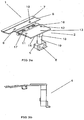
- the hinge assembly (2) is shown in detail in figure 2a .
- the hinge assembly consists of two mild steel plates (13) and (14), connected by a pin (15).
- the hinge assembly has two holes(11,12) on its surface as shown in figure 2a .
- the blade tip assembly (1) is connected with the plate (13) of hinge assembly (2) by bolting in the drilled holes (9) with (11) and (10) with (12).
- the adjacent blade assembly pairs vary in height by varying the dimension of the portion (4). This is important so that the flipping of an individual blade holder do not interact with the adjacent blade holder. For that purpose, the height of the adjacent blade assembly pairs is varied, so as to have a gap there between. This should be adequately clear from figure 1b in particular.
- figure 3a is an isometric view of a blade assembly pair comprising of one blade tip assembly (1) and one hinge assembly (2) of a belt scraper assembly, in assembled condition.
- the portion (4) consists of the cubical portion (18) and a cylindrical portion (19) with tapped hole (20).
- This portion (4) is elaborately shown in figure 5 .
- There is also a key (21) in portion(4) which is important to give limited rotational motion to the blade tip assembly (1). This motion is important to adjust the blade tip on varying surface profile.
- the plate (14) shown in figure 2a is connected along its basal surface to the top portion of the cubical portion (18) of portion (4), by welding along the respective flat portions. This should be clear from figure 3a .
- Figure 3b side view of the embodiment shown in figure 3a .
- Figure 4a is isometric view of plate member (6) shown in Figures 1a, 1b and 1c .
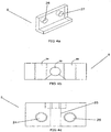
- Figures 4b and 4c are the top view and front view respectively of the locking unit (5) shown in Figures 1a, 1b and 1c .
- the locking unit (5) has a hole (22) in its top surface as shown in figure 4b .
- cylindrical portion(19) is attached to the locking unit(5) along its base , by bolting through the tapped hole(20) and through the hole(22), on the top surface of the locking unit(5).
- the locking unit(5) has a locking portion (23) which locks a key(21 best shown in figure 5 ) along the hole(22) to provide limited motion to the blade tip assembly(1).
- This figure also shows holes(24,25) existing in the front wall of the locking unit(5).
- Figure 4a shows the plate member(6) having holes(26,27) in the corresponding end wall of the plate member(6).
- the locking unit(5) is connected along its front wall to the plate member(6) by bolting through holes(24,25) in the front wall of the locking unit(5) and through corresponding holes(26,27) in the corresponding end wall of the plate member(6). This connection should be clear from figure 3a .
- the plate member (6) is connected to the chain(3) as shown in figure 1c . It is given tension using two coil springs connected at both the ends of the scraper assembly.
Landscapes
- Engineering & Computer Science (AREA)
- Mechanical Engineering (AREA)
- Belt Conveyors (AREA)
- Cleaning In General (AREA)
- Structure Of Belt Conveyors (AREA)
- Chain Conveyers (AREA)
- User Interface Of Digital Computer (AREA)
- Investigating Or Analyzing Materials By The Use Of Electric Means (AREA)
- Separation Using Semi-Permeable Membranes (AREA)
Description
- The present invention in general relates to belt scrapers for its application in bulk material handling belt conveyors and in particular, to a belt scraper assembly with an improved arrangement of at least one blade assembly connected to at least an hinge assembly on either side of a flexible member.
- In mining industry, conveyor belts are used to receive, transport, and deliver mined substances from one location to another for further processing or unloading.
- During the process, particles frequently accumulate on the conveyor belt surface. Without the removal of the particles, the conveyor belt may become inoperative.
- So, belt scrapers are used in bulk material handling belt conveyors to avoid material carry back, reduce spillage and keep belt clean. Clean belts help prevent material build up on snub pulley and return idlers and increase its life, thereby reducing cleaning cost, downtime cost and mis-tracking of the belt.
- In first generation Counter weight belt scraper, single blade design is made from thick rubber strip (wider than belt width) under the return belt and the counter weight provided at the side of the belt scraper with a pivot point to provide contact with the belt. The initial load exerted to the belt is approximately 80 - 90 Kgs. With time when the cleaning effectiveness reduces, the weight is increased and it can go up to 150 Kgs.
- Cleaning efficiency is approx 60-68 % and always, it is needed to increase counter weight load on a regular basis against blade wear. It is very less effective and high maintenance is involved.
- Second generation fixed mount belt scraper's segmented blades are made of hard alloy steel with rubber cushion at the bottom of blade mounted on a steel tube with both end fixed mount. It does not have automatic adjustments against blade wear. It provides inconsistent contact pressure to the belt which is approximately 100 - 125 Kgs.
- Cleaning efficiency is approx 70-85 % and always, there is need to lift-up of the fixed mount on a regular basis against blade wear. It is less effective and high maintenance involved.
- Pneumatically operated third generation belt scraper having segmented blades are made of hard alloy steel with or without polymer cushion at the bottom mounted of blade on a steel tube with ratchet and pinion mount and adjustment done through compressed air at 7-10 bars pneumatically. They provide inconsistent load to the belt of approximately 90 - 110 Kgs.
- Cleaning efficiency is approx 75-85 %. There is a need to pump air periodically to maintain the blade to belt contact due to drop in air pressure / leakage / chocking of air. Maintenance requirement is high.
- In fourth generation belt scrapers with shock absorbers semi automatic adjustments are present to some extent but, but there is a need for periodic manual adjustments against blade wear every 3 - 4 weeks interval. This type of belt scrapers have segmented type metallic blades with pivot point below the scraping edge mounted on a steel tube with both ends rubber shock absorber. It provides comparatively less load to the belt, which is approximately 24 - 80 Kgs.
- Cleaning efficiency is approx 92-95 %. It provides less consistency against heavy duty, high speed, vibration and bi-directional belt operation.
- Furthermore,
EP 90985 claim 1. - In general, the belt scraper assemblies were not sacrosanct and had one problem or the other, in operation and were not sacrosanct.
- Accordingly there is a long felt need to design a sacrosanct belt scraper assembly which ensures two layers of belt cleaning using a single member to carry the blades, eliminates misalignment of blades, ensures automatic adjustment of the blades, ensures, lesser wearing rate and no material build up, ensures size and reduction, easy installation, is suitable for various belt speeds and reduce maintenance costs, suitable for various material and in corrosive environment and ensures easy joining of sub assemblies.
- The present invention meets the aforesaid long felt need.
- All through out the specification including the claims, the words "conveyor belt", "scraper blade" "scraper holding arm", "spring", "washer", "stud", "blade", "blade tip", "blade tip assembly", "spring", "hinge assembly", "lock", "key" ,"chain " and "nut" are to be interpreted in the broadest sense of the respective terms and includes all similar items in the field known by other terms, as may be clear to persons skilled in the art. Restriction/limitation, if any, referred to in the specification, is solely by way of example and understanding the present invention.
- It is the principal object of the present invention to provide an improved belt scraper assembly for belt conveyors which ensures two layers of belt cleaning using a single member to carry the blades, eliminates misalignment of blades, ensures automatic adjustment of the blades and ensures lesser wearing rate and no material build up.
- It is a further object of the present invention to provide an improved belt scraper assembly for belt conveyors which ensures size and weight reduction and easy installation.
- It is another object of the present invention to provide an improved belt scrapper assembly for belt conveyor which is suitable for various belt speeds and reduce maintenance costs.
- It is yet another object of the present invention to provide an improved belt scrapper assembly for belt conveyor which is suitable for various materials and is suitable for working in corrosive environment.
- It is a further object of the present invention to provide an improved belt scraper assembly for belt conveyors which is suitable to be used up to 200°C.
- It is a further object of the present invention to provide an improved belt scraper assembly for belt conveyors which ensures easy joining of the subassemblies.
- It is another object of the present invention is to provide an improved belt scraper assembly for belt conveyors which have substantially high cleaning efficiency by way of twin blade cleaning.
- How the foregoing objects are achieved and other aspects of the present invention, will be clear from the following description which is purely by way of understanding and not by way of any sort of limitation.
- Accordingly, the present invention provides a belt scraper assembly for belt conveyors comprising at least a blade assembly and at least a hinge assembly mounted on either side of a supporting flexible member for facilitating twin blade cleaning, said blade assembly being operatively connected to said hinge assembly which is adapted to ensure limited rotational motion of said blade assembly.
- In accordance with preferred embodiments of the belt scraper assembly of the present invention:
- said blade assembly is a blade tip assembly comprising a tungsten carbide flexible tip directly contacted with the belt surface and brazed on a plate of mild steel, the latter having drilled holes on its surface and said flexible member is a chain or a wire;
- said hinge assembly comprises two mild steel plates connected by a pin, said plates being provided with drilled holes on its surface;
- said blade tip assembly is attached to said steel plate by bolting in the drilled holes with the corresponding drilled holes;
- said hinge assembly is provided with torsion springs for providing flipping motion to said blade assembly and said hinge assembly having mild steel plates, varies in length for adjacent blades, so that said flexible member (3) forms a curve;
- said steel plate of said hinge assembly is connected to a portion along its base, said portion being of adjustable dimension and having a cubical portion and a cylindrical portion with a tapped hole;
- said steel plate (14) is connected to said cubical portion (18) by bolting the respective flat portions;
- said cylindrical portion is attached to a locking unit along its base, by bolting through said tapped hole and through a hole in the top surface of said locking unit;
- said locking unit has a locking portion which locks a key along said hole to provide limited motion to said blade tip assembly;
- said locking unit is connected along its front wall to a plate member by bolting through holes in said front wall of said locking unit and through corresponding holes in the corresponding end wall of said plate member, said plate member being connected to said flexible member.
- The nature and scope of the present invention will be better understood from the accompanying drawings, which are by way of illustration of a preferred embodiment and not by way of any sort of limitation. In the accompanying drawings,
-
Figures 1a, 1b and1c illustrate top view, back view and the isometric view respectively of a preferred embodiment of the improved belt scraper assembly in accordance with a preferred embodiment of the present invention. -
Figure 2a is the top view of the hinge assembly shown inFigure 1a . -
Figure 2b is the isometric view of blade tip assembly shown in Figurela. -
Figures 3a and 3b are the isometric view and the side view of one blade tip assembly and one hinge assembly of a belt scraper assembly in assembled condition. -
Figure 4a is an isometric view ofplate member 6 shown inFigure 1a . -
Figures 4b and 4c are the top view and front view respectively of the locking unit shown inFig. 1a . -
Figure 5 is a flat isometric view of the portion marked 4 inFigure 1a . - The following describes a preferred embodiment of the present invention, which is purely for the sake of understanding the performance of the invention, and not by way of any sort of limitation.
Desired objectives of the belt scraper assembly according to the present invention: a. Eliminate misalignment of blades and ensures two layers of belt cleaning using a single member to carry the blades b. Reduce maintenance cost c. Automatic adjustment of the blades d. Suitable for various belt speeds e. Less blade wear rate f. Suitable for various material g. No material buildup h. Suitable to be used up to 200°C i. Size reduction j. Suitable to be used in the corrosive environment k. Weight Reduction l. Twin blade cleaning m. Easy installation - Many developments in the design of the scraper have been carried out. All of them individually solve certain problems but none of them meets the above objectives in a sacrosanct manner. There is always some problem or the other.
- The present invention brings all the above changes in a way never been done before. The blade elements in the present invention are carried on a flexible member such as but not limited to a wire or a chain, to keep the blades in contact with the belt throughout. The same flexible member supports at least two series of blades aligned on both the sides to provide twin blade cleaning. Moreover, all the blades have a flexible tip member which cleans the belt in normal condition but bends when it encounters a mechanical fastener or similar.
- For understanding the invention better, reference will now be made to the following preferred embodiment of the invention, which is illustrated in the accompanying drawings.
- In the figures like reference numerals represent like features.
- Turning first to
figure 1a , there is illustrated the blade scraper assembly of three blade holder assembly pairs (1, 2) connected to either side of a flexible chain(3). Thefigure 1a shows three such pairs (1, 2) on either side of the chain(3). There can be more. Minimum there should be one pair,i.e. one each of a blade tip assembly(1) and a hinge assembly(2) on either side of the chain(3). - Since, there are at least two such blade assemblies connected to both the sides of the flexible member such as chain, this arrangement provides two layers of belt cleaning using a single member to carry the blades. This was hitherto not achieved.
- The
figure 1b shows a back view of the assembly, whilefigure 1c being an isometric view thereof shows in greater detail the disposition of the elements of the assembly. It shows that the belt scrapper assembly has at least a blade tip assembly (1) connected to the hinge assembly (2) on either side of chain (3). The hinge assembly has a portion (4) connected to lower portion of its base. This portion in turn along its basal part is connected to a top portion of a locking unit (5). The locking unit (5) is connected along its front wall to a plate portion (6) along the end wall of the latter. This plate portion is connected to the chain (3). - The arrangement as stated in the preceding paragraph enables achieving all the objects of the present invention. How this is done is now explained with reference to the subsequent figures.
- The blade tip assembly (1) is shown in detail in
figure 2b , which directly comes in contact with the belt surface. It consists of a tungsten carbide tip (7) brazed on a plate of mild steel (8). There are at least two drilled holes (9, 10) on the surface of the mild steel plate (8). The flexible tip (7) cleans the belt in normal condition but bends when it encounters a mechanical fastener or similar. - The hinge assembly (2) is shown in detail in
figure 2a . The hinge assembly consists of two mild steel plates (13) and (14), connected by a pin (15). There is also a provision of two torsion springs (16) and (17), in the hinge assembly (2) to provide flipping motion to the blade tip assembly (1). The hinge assembly has two holes(11,12) on its surface as shown infigure 2a . - The blade tip assembly (1) is connected with the plate (13) of hinge assembly (2) by bolting in the drilled holes (9) with (11) and (10) with (12).
- The adjacent blade assembly pairs vary in height by varying the dimension of the portion (4). This is important so that the flipping of an individual blade holder do not interact with the adjacent blade holder. For that purpose, the height of the adjacent blade assembly pairs is varied, so as to have a gap there between. This should be adequately clear from
figure 1b in particular. - Further, from
figure 1a , it would be clear that that the unit (2) having mild steel plates (13, 14) varies in length for the adjacent blades, so that the chain forms a curve, which is important to generate the normal force against the belt surface. - The arrangements will be further clear from
figure 3a which is an isometric view of a blade assembly pair comprising of one blade tip assembly (1) and one hinge assembly (2) of a belt scraper assembly, in assembled condition. As shown in this figure the portion (4) consists of the cubical portion (18) and a cylindrical portion (19) with tapped hole (20). This portion (4) is elaborately shown infigure 5 . There is also a key (21) in portion(4) which is important to give limited rotational motion to the blade tip assembly (1). This motion is important to adjust the blade tip on varying surface profile. - The plate (14) shown in
figure 2a is connected along its basal surface to the top portion of the cubical portion (18) of portion (4), by welding along the respective flat portions. This should be clear fromfigure 3a . -
Figure 3b side view of the embodiment shown infigure 3a . -
Figure 4a is isometric view of plate member (6) shown inFigures 1a, 1b and1c .Figures 4b and 4c are the top view and front view respectively of the locking unit (5) shown inFigures 1a, 1b and1c . - The locking unit (5) has a hole (22) in its top surface as shown in
figure 4b . - Again referring back to
figure 3a , it would be clear that the cylindrical portion(19) is attached to the locking unit(5) along its base , by bolting through the tapped hole(20) and through the hole(22), on the top surface of the locking unit(5). - As shown in
figure 4c the locking unit(5) has a locking portion (23) which locks a key(21 best shown infigure 5 ) along the hole(22) to provide limited motion to the blade tip assembly(1). This figure also shows holes(24,25) existing in the front wall of the locking unit(5). -
Figure 4a shows the plate member(6) having holes(26,27) in the corresponding end wall of the plate member(6). - The locking unit(5) is connected along its front wall to the plate member(6) by bolting through holes(24,25) in the front wall of the locking unit(5) and through corresponding holes(26,27) in the corresponding end wall of the plate member(6). This connection should be clear from
figure 3a . - The plate member (6) is connected to the chain(3) as shown in
figure 1c . It is given tension using two coil springs connected at both the ends of the scraper assembly. - From the foregoing description and the appended claims it should be clear that all the desired objectives of the present invention are fulfilled.
- The present invention has been described with reference to some drawings and preferred embodiments, purely for the sake of understanding and not by way of any limitation and the present invention includes all legitimate developments within the scope of what has been described hereinbefore and claimed in the appended claims.
Claims (10)
- A belt scraper assembly for belt conveyors comprising at least a blade assembly (1) and at least a hinge assembly (2), said blade assembly (1) being operatively connected to said hinge assembly(2) which is adapted to ensure limited rotational motion of said blade assembly (1), characterized in that the belt scraper assembly comprises at least a blade assembly (1) and at least a hinge assembly (2) mounted on either side of a supporting flexible member(3) for facilitating twin blade cleaning.
- The belt scraper assembly as claimed in claim 1 wherein said blade assembly having a blade tip assembly(1) directly contacted with the belt surface comprising a tungsten carbide flexible tip(7) brazed on a plate of mild steel(8) adapted for cleaning the belt but bends on encountering a mechanical fastener or similar fastener, the latter having drilled holes(9,10) on its surface and said flexible member is a chain or a wire.
- The belt scraper assembly as claimed in claim 1 wherein said hinge assembly(2) comprises two mild steel plates(13,14) connected by a pin(15), said plates being provided with drilled holes(11,12) on its surface.
- The belt scraper assembly as claimed in claims 2 and 3 wherein said blade tip assembly(1) is attached to said steel plate(13) by bolting in the drilled holes(9,10) with the corresponding drilled holes(11,12).
- The belt scraper assembly as claimed in claims 2, 3 and 4 wherein said hinge assembly(2) is provided with torsion springs (16,17) for providing flipping motion to said blade assembly(1) and said hinge assembly(2) having mild steel plates(13,14) varies in length for adjacent blades, so that the flexible member(3) forms a curve.
- The belt scraper assembly as claimed in claim 3 wherein said steel plate(14) of said hinge assembly(2) is connected to a portion(4) along its base, said portion(4) being of adjustable dimension and having a cubical portion(18) and a cylindrical portion(19) with a tapped hole(20).
- The belt scrapper assembly as claimed in claim 6 wherein said steel plate (14) is connected to said cubical portion(18) by bolting the respective flat portions.
- The belt scrapper assembly as claimed in claim 6 wherein said cylindrical portion(19) is attached to a locking unit(5) along its base , by bolting through said tapped hole(20) and through a hole(22) in the top surface of said locking unit(5).
- The belt scraper assembly as claimed in claims 1, 5 and 8 wherein said locking unit(5) has a locking portion (23) which locks a key(21) along said hole(22) to provide limited motion to said blade tip assembly(1).
- The belt scraper assembly as claimed in claim 9 wherein said locking unit(5) is connected along its front wall to a plate member(6) by bolting through holes(24,25) in said front wall of said locking unit(5) and through corresponding holes(26,27) in the corresponding end wall of said plate member(6), said plate member(6) being connected to said flexible member(3).
Applications Claiming Priority (2)
| Application Number | Priority Date | Filing Date | Title |
|---|---|---|---|
| IN695KO2012 | 2012-06-26 | ||
| PCT/IN2013/000260 WO2014002112A1 (en) | 2012-06-26 | 2013-04-19 | Belt scraper assembly |
Publications (2)
| Publication Number | Publication Date |
|---|---|
| EP2864226A1 EP2864226A1 (en) | 2015-04-29 |
| EP2864226B1 true EP2864226B1 (en) | 2016-04-13 |
Family
ID=54188019
Family Applications (1)
| Application Number | Title | Priority Date | Filing Date |
|---|---|---|---|
| EP13729813.9A Not-in-force EP2864226B1 (en) | 2012-06-26 | 2013-04-19 | Belt scraper assembly |
Country Status (21)
| Country | Link |
|---|---|
| US (1) | US9278815B2 (en) |
| EP (1) | EP2864226B1 (en) |
| JP (1) | JP2015527271A (en) |
| KR (1) | KR20150032553A (en) |
| CN (1) | CN104428223B (en) |
| AP (1) | AP2014008134A0 (en) |
| AR (1) | AR091420A1 (en) |
| AU (1) | AU2013282728B2 (en) |
| BR (1) | BR112014030460A2 (en) |
| CA (1) | CA2874417A1 (en) |
| CL (1) | CL2014003414A1 (en) |
| EA (1) | EA201590038A1 (en) |
| ES (1) | ES2581887T3 (en) |
| MX (1) | MX2014014210A (en) |
| NZ (1) | NZ702329A (en) |
| PE (1) | PE20150173A1 (en) |
| PL (1) | PL2864226T3 (en) |
| PT (1) | PT2864226E (en) |
| SG (1) | SG11201407785YA (en) |
| WO (1) | WO2014002112A1 (en) |
| ZA (1) | ZA201408606B (en) |
Families Citing this family (6)
| Publication number | Priority date | Publication date | Assignee | Title |
|---|---|---|---|---|
| DE102013113934B3 (en) * | 2013-12-12 | 2015-02-26 | Wilfried Dünnwald | Device for stripping material from a conveyor belt of a belt conveyor |
| CN105936410A (en) * | 2016-06-22 | 2016-09-14 | 陕西陕煤黄陵矿业有限公司 | Mining conveying adhesive tape water removal cleaning device |
| MX364082B (en) * | 2017-06-05 | 2019-04-11 | Heat Control Inc | Mass shaped detaching razor device and system thereof. |
| WO2020200441A1 (en) * | 2019-04-03 | 2020-10-08 | Schulte Strathaus GmbH & Co. KG Fördertechnik Dichtungssysteme | Conveyor belt scraping device and displacement guide therefor |
| CN111632890A (en) * | 2020-05-29 | 2020-09-08 | 红云红河烟草(集团)有限责任公司 | A cigarette paper conveying track cleaning device and a cigarette paper conveying device |
| KR102833883B1 (en) * | 2023-04-07 | 2025-07-11 | 이현우 | Cutting equipment with rotating cutter installed by magnetic force |
Family Cites Families (27)
| Publication number | Priority date | Publication date | Assignee | Title |
|---|---|---|---|---|
| US4352425A (en) * | 1981-04-22 | 1982-10-05 | Ray Childress | Belt cleaner |
| US4428090A (en) * | 1982-03-02 | 1984-01-31 | Coggin Michael E | Pallet scraper |
| DE3211626A1 (en) * | 1982-03-30 | 1983-10-20 | Hosch-Fördertechnik GmbH, 4350 Recklinghausen | STRIP DEVICE FOR BELT TAPES |
| US4703845A (en) * | 1985-11-19 | 1987-11-03 | Veenhof Willem D | Scraper strands for conveyor belt cleaners |
| GB8625768D0 (en) * | 1986-10-28 | 1986-12-03 | Doncaster Conveyor Improv | Conveyor belt cleaning apparatus |
| JPS649913U (en) * | 1987-07-09 | 1989-01-19 | ||
| JPH03162309A (en) * | 1989-11-18 | 1991-07-12 | Nkk Corp | Scraper type belt cleaner |
| US5011002A (en) * | 1989-12-26 | 1991-04-30 | Asgco Manufacturing, Inc. | Scraper apparatus for conveyor belts |
| US5222588A (en) * | 1991-01-29 | 1993-06-29 | Gordon Belt Scrapers, Inc. | Secondary conveyor belt cleaners |
| JPH10203635A (en) * | 1997-01-23 | 1998-08-04 | Sumitomo Metal Ind Ltd | Cleaner device for belt conveyor |
| JPH10329929A (en) * | 1997-05-29 | 1998-12-15 | Noda Tec:Kk | Cleaner for conveyor belt |
| JPH1135135A (en) * | 1997-07-18 | 1999-02-09 | Nippon Tsusho Kk | Belt cleaner device and scraper for this device and manufacture of scraper |
| US6152290A (en) * | 1997-09-26 | 2000-11-28 | Asgco Manufacturing, Inc. | Cleaning device for conveyor belt assembly |
| JP2000246583A (en) * | 1999-03-02 | 2000-09-12 | Murata Mach Ltd | Chip conveyer device |
| US6681919B1 (en) * | 1999-06-24 | 2004-01-27 | Slic Trading Company Limited | Scraper bias apparatus |
| CA2385687C (en) * | 1999-09-27 | 2008-11-04 | Mato Australia Pty Ltd | Conveyor belt cleaner tensioning device |
| US6749725B1 (en) * | 1999-10-06 | 2004-06-15 | Metso Paper, Inc. | Blade holder for a doctor and a method for using the doctor |
| US6948609B2 (en) * | 2000-03-23 | 2005-09-27 | Asgco Manufacturing, Inc. | Light duty belt cleaning system |
| US6633739B2 (en) * | 2001-12-17 | 2003-10-14 | Xerox Corporation | Detoning blade |
| UA80285C2 (en) * | 2002-08-14 | 2007-09-10 | Hans-Otto Schvartse | Device for stripping impurities from belts in conveying systems |
| US6843363B2 (en) * | 2002-08-14 | 2005-01-18 | Hans-Otto Schwarze | Stripping device for the return run area of conveyor belts |
| US7303000B2 (en) * | 2004-08-03 | 2007-12-04 | Spx Corporation | Mounting system and method for scraped surface heat exchanger blades |
| JP2008260628A (en) * | 2007-04-16 | 2008-10-30 | Tetsuo Harada | Belt cleaning device |
| DE102008017101B4 (en) * | 2008-04-03 | 2010-06-10 | Dünnwald, Wilfried | Arrangement for stripping material from the carrying side of a conveyor belt via a space curve on the discharge drum with integrated, flexible carrier material and flexible stripping element |
| US7950519B2 (en) * | 2008-05-02 | 2011-05-31 | Flexible Steel Lacing Company | Belt scraper assembly and scraper blade thereof |
| FR2976930B1 (en) * | 2011-06-22 | 2015-09-04 | Rene Brunone | RIPPER DEVICE FOR CONVEYOR BELT AND METHOD OF MANUFACTURING SAME |
| US8662282B1 (en) * | 2012-11-07 | 2014-03-04 | Ford Motor Company | Pallet conveyor debris wiper |
-
2013
- 2013-04-19 BR BR112014030460A patent/BR112014030460A2/en not_active IP Right Cessation
- 2013-04-19 PT PT137298139T patent/PT2864226E/en unknown
- 2013-04-19 KR KR1020157000629A patent/KR20150032553A/en not_active Ceased
- 2013-04-19 JP JP2015519494A patent/JP2015527271A/en active Pending
- 2013-04-19 NZ NZ702329A patent/NZ702329A/en not_active IP Right Cessation
- 2013-04-19 CA CA2874417A patent/CA2874417A1/en not_active Abandoned
- 2013-04-19 PE PE2014002448A patent/PE20150173A1/en not_active Application Discontinuation
- 2013-04-19 EA EA201590038A patent/EA201590038A1/en unknown
- 2013-04-19 WO PCT/IN2013/000260 patent/WO2014002112A1/en not_active Ceased
- 2013-04-19 EP EP13729813.9A patent/EP2864226B1/en not_active Not-in-force
- 2013-04-19 ES ES13729813.9T patent/ES2581887T3/en active Active
- 2013-04-19 AU AU2013282728A patent/AU2013282728B2/en not_active Ceased
- 2013-04-19 US US14/407,732 patent/US9278815B2/en not_active Expired - Fee Related
- 2013-04-19 PL PL13729813.9T patent/PL2864226T3/en unknown
- 2013-04-19 SG SG11201407785YA patent/SG11201407785YA/en unknown
- 2013-04-19 CN CN201380034272.7A patent/CN104428223B/en not_active Expired - Fee Related
- 2013-04-19 MX MX2014014210A patent/MX2014014210A/en unknown
- 2013-04-19 AP AP2014008134A patent/AP2014008134A0/en unknown
- 2013-06-12 AR ARP130102064 patent/AR091420A1/en not_active Application Discontinuation
-
2014
- 2014-11-24 ZA ZA2014/08606A patent/ZA201408606B/en unknown
- 2014-12-16 CL CL2014003414A patent/CL2014003414A1/en unknown
Also Published As
| Publication number | Publication date |
|---|---|
| ZA201408606B (en) | 2016-01-27 |
| US20150151924A1 (en) | 2015-06-04 |
| PE20150173A1 (en) | 2015-03-07 |
| EA201590038A1 (en) | 2015-03-31 |
| ES2581887T3 (en) | 2016-09-08 |
| PT2864226E (en) | 2016-06-08 |
| WO2014002112A1 (en) | 2014-01-03 |
| PL2864226T3 (en) | 2016-10-31 |
| CN104428223B (en) | 2016-06-29 |
| EP2864226A1 (en) | 2015-04-29 |
| AU2013282728A1 (en) | 2014-12-18 |
| KR20150032553A (en) | 2015-03-26 |
| CA2874417A1 (en) | 2014-01-03 |
| CN104428223A (en) | 2015-03-18 |
| CL2014003414A1 (en) | 2015-02-13 |
| US9278815B2 (en) | 2016-03-08 |
| SG11201407785YA (en) | 2015-01-29 |
| AP2014008134A0 (en) | 2014-12-31 |
| MX2014014210A (en) | 2015-02-12 |
| JP2015527271A (en) | 2015-09-17 |
| BR112014030460A2 (en) | 2017-06-27 |
| AU2013282728B2 (en) | 2017-06-01 |
| AR091420A1 (en) | 2015-02-04 |
| NZ702329A (en) | 2016-05-27 |
Similar Documents
| Publication | Publication Date | Title |
|---|---|---|
| AU2013282728B2 (en) | Belt scraper assembly | |
| US9469484B2 (en) | Belt scraper assembly | |
| EP2802521B1 (en) | An improved belt scraper mounting | |
| EP2336055B1 (en) | Conveyor belt cleaning system | |
| US6874616B2 (en) | Conveyor belt cleaning system | |
| US20160340128A1 (en) | Conveyor belt scraper | |
| US6360875B1 (en) | Conveyor belt scraper tensioner | |
| WO2016116940A1 (en) | Auto adjusting scraper | |
| US9415946B2 (en) | Replaceable blade for reversible belt scraper | |
| AU2020102942A4 (en) | Self-aligning conveyor belt cleaning assembly | |
| CN206345389U (en) | Scraper and conveying equipment | |
| KR200440122Y1 (en) | Conveyor Belt Cleaner | |
| CN214651540U (en) | Rubber elastic tensioner for sweeper | |
| JP2004231319A (en) | Belt cleaner device | |
| CN207511261U (en) | Plate-type feeding with sprocket wheel picking-up device | |
| NZ627566B2 (en) | An improved belt scraper mounting |
Legal Events
| Date | Code | Title | Description |
|---|---|---|---|
| PUAI | Public reference made under article 153(3) epc to a published international application that has entered the european phase |
Free format text: ORIGINAL CODE: 0009012 |
|
| 17P | Request for examination filed |
Effective date: 20141119 |
|
| AK | Designated contracting states |
Kind code of ref document: A1 Designated state(s): AL AT BE BG CH CY CZ DE DK EE ES FI FR GB GR HR HU IE IS IT LI LT LU LV MC MK MT NL NO PL PT RO RS SE SI SK SM TR |
|
| AX | Request for extension of the european patent |
Extension state: BA ME |
|
| DAX | Request for extension of the european patent (deleted) | ||
| GRAP | Despatch of communication of intention to grant a patent |
Free format text: ORIGINAL CODE: EPIDOSNIGR1 |
|
| INTG | Intention to grant announced |
Effective date: 20151208 |
|
| GRAS | Grant fee paid |
Free format text: ORIGINAL CODE: EPIDOSNIGR3 |
|
| GRAA | (expected) grant |
Free format text: ORIGINAL CODE: 0009210 |
|
| REG | Reference to a national code |
Ref country code: RO Ref legal event code: EPE |
|
| AK | Designated contracting states |
Kind code of ref document: B1 Designated state(s): AL AT BE BG CH CY CZ DE DK EE ES FI FR GB GR HR HU IE IS IT LI LT LU LV MC MK MT NL NO PL PT RO RS SE SI SK SM TR |
|
| REG | Reference to a national code |
Ref country code: GB Ref legal event code: FG4D |
|
| REG | Reference to a national code |
Ref country code: AT Ref legal event code: REF Ref document number: 789872 Country of ref document: AT Kind code of ref document: T Effective date: 20160415 Ref country code: CH Ref legal event code: EP |
|
| REG | Reference to a national code |
Ref country code: IE Ref legal event code: FG4D |
|
| REG | Reference to a national code |
Ref country code: DE Ref legal event code: R096 Ref document number: 602013006543 Country of ref document: DE |
|
| REG | Reference to a national code |
Ref country code: PT Ref legal event code: SC4A Free format text: AVAILABILITY OF NATIONAL TRANSLATION Effective date: 20160601 |
|
| REG | Reference to a national code |
Ref country code: NL Ref legal event code: FP Ref country code: FR Ref legal event code: PLFP Year of fee payment: 4 |
|
| PGFP | Annual fee paid to national office [announced via postgrant information from national office to epo] |
Ref country code: FI Payment date: 20160524 Year of fee payment: 4 Ref country code: IE Payment date: 20160603 Year of fee payment: 4 |
|
| REG | Reference to a national code |
Ref country code: SE Ref legal event code: TRGR |
|
| REG | Reference to a national code |
Ref country code: LT Ref legal event code: MG4D |
|
| PG25 | Lapsed in a contracting state [announced via postgrant information from national office to epo] |
Ref country code: BE Free format text: LAPSE BECAUSE OF NON-PAYMENT OF DUE FEES Effective date: 20160430 |
|
| PGFP | Annual fee paid to national office [announced via postgrant information from national office to epo] |
Ref country code: PT Payment date: 20160607 Year of fee payment: 4 Ref country code: NL Payment date: 20160530 Year of fee payment: 4 Ref country code: FR Payment date: 20160610 Year of fee payment: 4 Ref country code: TR Payment date: 20160603 Year of fee payment: 4 |
|
| REG | Reference to a national code |
Ref country code: ES Ref legal event code: FG2A Ref document number: 2581887 Country of ref document: ES Kind code of ref document: T3 Effective date: 20160908 |
|
| PG25 | Lapsed in a contracting state [announced via postgrant information from national office to epo] |
Ref country code: NO Free format text: LAPSE BECAUSE OF FAILURE TO SUBMIT A TRANSLATION OF THE DESCRIPTION OR TO PAY THE FEE WITHIN THE PRESCRIBED TIME-LIMIT Effective date: 20160713 Ref country code: LT Free format text: LAPSE BECAUSE OF FAILURE TO SUBMIT A TRANSLATION OF THE DESCRIPTION OR TO PAY THE FEE WITHIN THE PRESCRIBED TIME-LIMIT Effective date: 20160413 |
|
| PGFP | Annual fee paid to national office [announced via postgrant information from national office to epo] |
Ref country code: DE Payment date: 20160628 Year of fee payment: 4 |
|
| PG25 | Lapsed in a contracting state [announced via postgrant information from national office to epo] |
Ref country code: LV Free format text: LAPSE BECAUSE OF FAILURE TO SUBMIT A TRANSLATION OF THE DESCRIPTION OR TO PAY THE FEE WITHIN THE PRESCRIBED TIME-LIMIT Effective date: 20160413 Ref country code: RS Free format text: LAPSE BECAUSE OF FAILURE TO SUBMIT A TRANSLATION OF THE DESCRIPTION OR TO PAY THE FEE WITHIN THE PRESCRIBED TIME-LIMIT Effective date: 20160413 Ref country code: HR Free format text: LAPSE BECAUSE OF FAILURE TO SUBMIT A TRANSLATION OF THE DESCRIPTION OR TO PAY THE FEE WITHIN THE PRESCRIBED TIME-LIMIT Effective date: 20160413 |
|
| PGFP | Annual fee paid to national office [announced via postgrant information from national office to epo] |
Ref country code: GR Payment date: 20160721 Year of fee payment: 4 Ref country code: PL Payment date: 20160517 Year of fee payment: 4 Ref country code: RO Payment date: 20160513 Year of fee payment: 4 |
|
| REG | Reference to a national code |
Ref country code: CH Ref legal event code: PL |
|
| PG25 | Lapsed in a contracting state [announced via postgrant information from national office to epo] |
Ref country code: BE Free format text: LAPSE BECAUSE OF FAILURE TO SUBMIT A TRANSLATION OF THE DESCRIPTION OR TO PAY THE FEE WITHIN THE PRESCRIBED TIME-LIMIT Effective date: 20160413 |
|
| REG | Reference to a national code |
Ref country code: DE Ref legal event code: R097 Ref document number: 602013006543 Country of ref document: DE |
|
| PG25 | Lapsed in a contracting state [announced via postgrant information from national office to epo] |
Ref country code: CH Free format text: LAPSE BECAUSE OF NON-PAYMENT OF DUE FEES Effective date: 20160430 Ref country code: EE Free format text: LAPSE BECAUSE OF FAILURE TO SUBMIT A TRANSLATION OF THE DESCRIPTION OR TO PAY THE FEE WITHIN THE PRESCRIBED TIME-LIMIT Effective date: 20160413 Ref country code: MC Free format text: LAPSE BECAUSE OF FAILURE TO SUBMIT A TRANSLATION OF THE DESCRIPTION OR TO PAY THE FEE WITHIN THE PRESCRIBED TIME-LIMIT Effective date: 20160413 Ref country code: SK Free format text: LAPSE BECAUSE OF FAILURE TO SUBMIT A TRANSLATION OF THE DESCRIPTION OR TO PAY THE FEE WITHIN THE PRESCRIBED TIME-LIMIT Effective date: 20160413 Ref country code: CZ Free format text: LAPSE BECAUSE OF FAILURE TO SUBMIT A TRANSLATION OF THE DESCRIPTION OR TO PAY THE FEE WITHIN THE PRESCRIBED TIME-LIMIT Effective date: 20160413 Ref country code: DK Free format text: LAPSE BECAUSE OF FAILURE TO SUBMIT A TRANSLATION OF THE DESCRIPTION OR TO PAY THE FEE WITHIN THE PRESCRIBED TIME-LIMIT Effective date: 20160413 Ref country code: LI Free format text: LAPSE BECAUSE OF NON-PAYMENT OF DUE FEES Effective date: 20160430 |
|
| REG | Reference to a national code |
Ref country code: GR Ref legal event code: EP Ref document number: 20160401588 Country of ref document: GR Effective date: 20161020 |
|
| PLBE | No opposition filed within time limit |
Free format text: ORIGINAL CODE: 0009261 |
|
| STAA | Information on the status of an ep patent application or granted ep patent |
Free format text: STATUS: NO OPPOSITION FILED WITHIN TIME LIMIT |
|
| PG25 | Lapsed in a contracting state [announced via postgrant information from national office to epo] |
Ref country code: SM Free format text: LAPSE BECAUSE OF FAILURE TO SUBMIT A TRANSLATION OF THE DESCRIPTION OR TO PAY THE FEE WITHIN THE PRESCRIBED TIME-LIMIT Effective date: 20160413 |
|
| 26N | No opposition filed |
Effective date: 20170116 |
|
| PG25 | Lapsed in a contracting state [announced via postgrant information from national office to epo] |
Ref country code: SI Free format text: LAPSE BECAUSE OF FAILURE TO SUBMIT A TRANSLATION OF THE DESCRIPTION OR TO PAY THE FEE WITHIN THE PRESCRIBED TIME-LIMIT Effective date: 20160413 |
|
| PGFP | Annual fee paid to national office [announced via postgrant information from national office to epo] |
Ref country code: ES Payment date: 20170526 Year of fee payment: 5 Ref country code: SE Payment date: 20170531 Year of fee payment: 5 |
|
| REG | Reference to a national code |
Ref country code: DE Ref legal event code: R119 Ref document number: 602013006543 Country of ref document: DE |
|
| REG | Reference to a national code |
Ref country code: NL Ref legal event code: MM Effective date: 20170501 |
|
| GBPC | Gb: european patent ceased through non-payment of renewal fee |
Effective date: 20170419 |
|
| REG | Reference to a national code |
Ref country code: IE Ref legal event code: MM4A |
|
| REG | Reference to a national code |
Ref country code: FR Ref legal event code: ST Effective date: 20171229 |
|
| PG25 | Lapsed in a contracting state [announced via postgrant information from national office to epo] |
Ref country code: RO Free format text: LAPSE BECAUSE OF NON-PAYMENT OF DUE FEES Effective date: 20170419 Ref country code: FR Free format text: LAPSE BECAUSE OF NON-PAYMENT OF DUE FEES Effective date: 20170502 Ref country code: NL Free format text: LAPSE BECAUSE OF NON-PAYMENT OF DUE FEES Effective date: 20170501 Ref country code: FI Free format text: LAPSE BECAUSE OF NON-PAYMENT OF DUE FEES Effective date: 20170419 Ref country code: DE Free format text: LAPSE BECAUSE OF NON-PAYMENT OF DUE FEES Effective date: 20171103 |
|
| PG25 | Lapsed in a contracting state [announced via postgrant information from national office to epo] |
Ref country code: GB Free format text: LAPSE BECAUSE OF NON-PAYMENT OF DUE FEES Effective date: 20170419 Ref country code: GR Free format text: LAPSE BECAUSE OF NON-PAYMENT OF DUE FEES Effective date: 20171103 |
|
| PG25 | Lapsed in a contracting state [announced via postgrant information from national office to epo] |
Ref country code: IE Free format text: LAPSE BECAUSE OF NON-PAYMENT OF DUE FEES Effective date: 20170419 |
|
| PG25 | Lapsed in a contracting state [announced via postgrant information from national office to epo] |
Ref country code: IT Free format text: LAPSE BECAUSE OF NON-PAYMENT OF DUE FEES Effective date: 20170419 Ref country code: PT Free format text: LAPSE BECAUSE OF NON-PAYMENT OF DUE FEES Effective date: 20180119 Ref country code: HU Free format text: LAPSE BECAUSE OF FAILURE TO SUBMIT A TRANSLATION OF THE DESCRIPTION OR TO PAY THE FEE WITHIN THE PRESCRIBED TIME-LIMIT; INVALID AB INITIO Effective date: 20130419 |
|
| PG25 | Lapsed in a contracting state [announced via postgrant information from national office to epo] |
Ref country code: MT Free format text: LAPSE BECAUSE OF NON-PAYMENT OF DUE FEES Effective date: 20160430 Ref country code: MK Free format text: LAPSE BECAUSE OF FAILURE TO SUBMIT A TRANSLATION OF THE DESCRIPTION OR TO PAY THE FEE WITHIN THE PRESCRIBED TIME-LIMIT Effective date: 20160413 Ref country code: CY Free format text: LAPSE BECAUSE OF FAILURE TO SUBMIT A TRANSLATION OF THE DESCRIPTION OR TO PAY THE FEE WITHIN THE PRESCRIBED TIME-LIMIT Effective date: 20160413 Ref country code: LU Free format text: LAPSE BECAUSE OF NON-PAYMENT OF DUE FEES Effective date: 20160419 Ref country code: IS Free format text: LAPSE BECAUSE OF FAILURE TO SUBMIT A TRANSLATION OF THE DESCRIPTION OR TO PAY THE FEE WITHIN THE PRESCRIBED TIME-LIMIT Effective date: 20160413 |
|
| PG25 | Lapsed in a contracting state [announced via postgrant information from national office to epo] |
Ref country code: BG Free format text: LAPSE BECAUSE OF FAILURE TO SUBMIT A TRANSLATION OF THE DESCRIPTION OR TO PAY THE FEE WITHIN THE PRESCRIBED TIME-LIMIT Effective date: 20160413 |
|
| PG25 | Lapsed in a contracting state [announced via postgrant information from national office to epo] |
Ref country code: PL Free format text: LAPSE BECAUSE OF NON-PAYMENT OF DUE FEES Effective date: 20170419 Ref country code: AL Free format text: LAPSE BECAUSE OF FAILURE TO SUBMIT A TRANSLATION OF THE DESCRIPTION OR TO PAY THE FEE WITHIN THE PRESCRIBED TIME-LIMIT Effective date: 20160413 |
|
| REG | Reference to a national code |
Ref country code: SE Ref legal event code: EUG |
|
| REG | Reference to a national code |
Ref country code: AT Ref legal event code: UEP Ref document number: 789872 Country of ref document: AT Kind code of ref document: T Effective date: 20160413 |
|
| PG25 | Lapsed in a contracting state [announced via postgrant information from national office to epo] |
Ref country code: SE Free format text: LAPSE BECAUSE OF NON-PAYMENT OF DUE FEES Effective date: 20180420 |
|
| REG | Reference to a national code |
Ref country code: AT Ref legal event code: MM01 Ref document number: 789872 Country of ref document: AT Kind code of ref document: T Effective date: 20180419 |
|
| REG | Reference to a national code |
Ref country code: ES Ref legal event code: FD2A Effective date: 20190911 |
|
| PG25 | Lapsed in a contracting state [announced via postgrant information from national office to epo] |
Ref country code: AT Free format text: LAPSE BECAUSE OF NON-PAYMENT OF DUE FEES Effective date: 20180419 Ref country code: ES Free format text: LAPSE BECAUSE OF NON-PAYMENT OF DUE FEES Effective date: 20180420 |
|
| PG25 | Lapsed in a contracting state [announced via postgrant information from national office to epo] |
Ref country code: TR Free format text: LAPSE BECAUSE OF NON-PAYMENT OF DUE FEES Effective date: 20170419 |