EP2864150B1 - Method for controlling the charging of a battery of an electric vehicle in a non-contact charging system - Google Patents
Method for controlling the charging of a battery of an electric vehicle in a non-contact charging system Download PDFInfo
- Publication number
- EP2864150B1 EP2864150B1 EP13733384.5A EP13733384A EP2864150B1 EP 2864150 B1 EP2864150 B1 EP 2864150B1 EP 13733384 A EP13733384 A EP 13733384A EP 2864150 B1 EP2864150 B1 EP 2864150B1
- Authority
- EP
- European Patent Office
- Prior art keywords
- inverter
- current
- load
- power
- battery
- Prior art date
- Legal status (The legal status is an assumption and is not a legal conclusion. Google has not performed a legal analysis and makes no representation as to the accuracy of the status listed.)
- Active
Links
- 238000000034 method Methods 0.000 title claims description 26
- 230000000295 complement effect Effects 0.000 claims description 4
- 230000005540 biological transmission Effects 0.000 claims 1
- 238000010586 diagram Methods 0.000 description 6
- 230000001276 controlling effect Effects 0.000 description 5
- 230000001105 regulatory effect Effects 0.000 description 4
- 238000005259 measurement Methods 0.000 description 3
- 230000015572 biosynthetic process Effects 0.000 description 1
- 238000011217 control strategy Methods 0.000 description 1
- 230000008878 coupling Effects 0.000 description 1
- 238000010168 coupling process Methods 0.000 description 1
- 238000005859 coupling reaction Methods 0.000 description 1
- 125000004122 cyclic group Chemical group 0.000 description 1
- 238000001914 filtration Methods 0.000 description 1
- 230000001939 inductive effect Effects 0.000 description 1
- 238000003786 synthesis reaction Methods 0.000 description 1
- 238000004804 winding Methods 0.000 description 1
Images


Classifications
-
- B—PERFORMING OPERATIONS; TRANSPORTING
- B60—VEHICLES IN GENERAL
- B60L—PROPULSION OF ELECTRICALLY-PROPELLED VEHICLES; SUPPLYING ELECTRIC POWER FOR AUXILIARY EQUIPMENT OF ELECTRICALLY-PROPELLED VEHICLES; ELECTRODYNAMIC BRAKE SYSTEMS FOR VEHICLES IN GENERAL; MAGNETIC SUSPENSION OR LEVITATION FOR VEHICLES; MONITORING OPERATING VARIABLES OF ELECTRICALLY-PROPELLED VEHICLES; ELECTRIC SAFETY DEVICES FOR ELECTRICALLY-PROPELLED VEHICLES
- B60L53/00—Methods of charging batteries, specially adapted for electric vehicles; Charging stations or on-board charging equipment therefor; Exchange of energy storage elements in electric vehicles
- B60L53/10—Methods of charging batteries, specially adapted for electric vehicles; Charging stations or on-board charging equipment therefor; Exchange of energy storage elements in electric vehicles characterised by the energy transfer between the charging station and the vehicle
- B60L53/12—Inductive energy transfer
-
- B—PERFORMING OPERATIONS; TRANSPORTING
- B60—VEHICLES IN GENERAL
- B60L—PROPULSION OF ELECTRICALLY-PROPELLED VEHICLES; SUPPLYING ELECTRIC POWER FOR AUXILIARY EQUIPMENT OF ELECTRICALLY-PROPELLED VEHICLES; ELECTRODYNAMIC BRAKE SYSTEMS FOR VEHICLES IN GENERAL; MAGNETIC SUSPENSION OR LEVITATION FOR VEHICLES; MONITORING OPERATING VARIABLES OF ELECTRICALLY-PROPELLED VEHICLES; ELECTRIC SAFETY DEVICES FOR ELECTRICALLY-PROPELLED VEHICLES
- B60L53/00—Methods of charging batteries, specially adapted for electric vehicles; Charging stations or on-board charging equipment therefor; Exchange of energy storage elements in electric vehicles
- B60L53/30—Constructional details of charging stations
- B60L53/35—Means for automatic or assisted adjustment of the relative position of charging devices and vehicles
- B60L53/36—Means for automatic or assisted adjustment of the relative position of charging devices and vehicles by positioning the vehicle
-
- H—ELECTRICITY
- H02—GENERATION; CONVERSION OR DISTRIBUTION OF ELECTRIC POWER
- H02J—CIRCUIT ARRANGEMENTS OR SYSTEMS FOR SUPPLYING OR DISTRIBUTING ELECTRIC POWER; SYSTEMS FOR STORING ELECTRIC ENERGY
- H02J50/00—Circuit arrangements or systems for wireless supply or distribution of electric power
- H02J50/10—Circuit arrangements or systems for wireless supply or distribution of electric power using inductive coupling
- H02J50/12—Circuit arrangements or systems for wireless supply or distribution of electric power using inductive coupling of the resonant type
-
- H—ELECTRICITY
- H02—GENERATION; CONVERSION OR DISTRIBUTION OF ELECTRIC POWER
- H02J—CIRCUIT ARRANGEMENTS OR SYSTEMS FOR SUPPLYING OR DISTRIBUTING ELECTRIC POWER; SYSTEMS FOR STORING ELECTRIC ENERGY
- H02J7/00—Circuit arrangements for charging or depolarising batteries or for supplying loads from batteries
- H02J7/007—Regulation of charging or discharging current or voltage
-
- B—PERFORMING OPERATIONS; TRANSPORTING
- B60—VEHICLES IN GENERAL
- B60L—PROPULSION OF ELECTRICALLY-PROPELLED VEHICLES; SUPPLYING ELECTRIC POWER FOR AUXILIARY EQUIPMENT OF ELECTRICALLY-PROPELLED VEHICLES; ELECTRODYNAMIC BRAKE SYSTEMS FOR VEHICLES IN GENERAL; MAGNETIC SUSPENSION OR LEVITATION FOR VEHICLES; MONITORING OPERATING VARIABLES OF ELECTRICALLY-PROPELLED VEHICLES; ELECTRIC SAFETY DEVICES FOR ELECTRICALLY-PROPELLED VEHICLES
- B60L2210/00—Converter types
- B60L2210/10—DC to DC converters
-
- B—PERFORMING OPERATIONS; TRANSPORTING
- B60—VEHICLES IN GENERAL
- B60L—PROPULSION OF ELECTRICALLY-PROPELLED VEHICLES; SUPPLYING ELECTRIC POWER FOR AUXILIARY EQUIPMENT OF ELECTRICALLY-PROPELLED VEHICLES; ELECTRODYNAMIC BRAKE SYSTEMS FOR VEHICLES IN GENERAL; MAGNETIC SUSPENSION OR LEVITATION FOR VEHICLES; MONITORING OPERATING VARIABLES OF ELECTRICALLY-PROPELLED VEHICLES; ELECTRIC SAFETY DEVICES FOR ELECTRICALLY-PROPELLED VEHICLES
- B60L2210/00—Converter types
- B60L2210/30—AC to DC converters
-
- B—PERFORMING OPERATIONS; TRANSPORTING
- B60—VEHICLES IN GENERAL
- B60L—PROPULSION OF ELECTRICALLY-PROPELLED VEHICLES; SUPPLYING ELECTRIC POWER FOR AUXILIARY EQUIPMENT OF ELECTRICALLY-PROPELLED VEHICLES; ELECTRODYNAMIC BRAKE SYSTEMS FOR VEHICLES IN GENERAL; MAGNETIC SUSPENSION OR LEVITATION FOR VEHICLES; MONITORING OPERATING VARIABLES OF ELECTRICALLY-PROPELLED VEHICLES; ELECTRIC SAFETY DEVICES FOR ELECTRICALLY-PROPELLED VEHICLES
- B60L2210/00—Converter types
- B60L2210/40—DC to AC converters
-
- B—PERFORMING OPERATIONS; TRANSPORTING
- B60—VEHICLES IN GENERAL
- B60Y—INDEXING SCHEME RELATING TO ASPECTS CROSS-CUTTING VEHICLE TECHNOLOGY
- B60Y2200/00—Type of vehicle
- B60Y2200/90—Vehicles comprising electric prime movers
- B60Y2200/91—Electric vehicles
-
- B—PERFORMING OPERATIONS; TRANSPORTING
- B60—VEHICLES IN GENERAL
- B60Y—INDEXING SCHEME RELATING TO ASPECTS CROSS-CUTTING VEHICLE TECHNOLOGY
- B60Y2200/00—Type of vehicle
- B60Y2200/90—Vehicles comprising electric prime movers
- B60Y2200/92—Hybrid vehicles
-
- Y—GENERAL TAGGING OF NEW TECHNOLOGICAL DEVELOPMENTS; GENERAL TAGGING OF CROSS-SECTIONAL TECHNOLOGIES SPANNING OVER SEVERAL SECTIONS OF THE IPC; TECHNICAL SUBJECTS COVERED BY FORMER USPC CROSS-REFERENCE ART COLLECTIONS [XRACs] AND DIGESTS
- Y02—TECHNOLOGIES OR APPLICATIONS FOR MITIGATION OR ADAPTATION AGAINST CLIMATE CHANGE
- Y02T—CLIMATE CHANGE MITIGATION TECHNOLOGIES RELATED TO TRANSPORTATION
- Y02T10/00—Road transport of goods or passengers
- Y02T10/60—Other road transportation technologies with climate change mitigation effect
- Y02T10/70—Energy storage systems for electromobility, e.g. batteries
-
- Y—GENERAL TAGGING OF NEW TECHNOLOGICAL DEVELOPMENTS; GENERAL TAGGING OF CROSS-SECTIONAL TECHNOLOGIES SPANNING OVER SEVERAL SECTIONS OF THE IPC; TECHNICAL SUBJECTS COVERED BY FORMER USPC CROSS-REFERENCE ART COLLECTIONS [XRACs] AND DIGESTS
- Y02—TECHNOLOGIES OR APPLICATIONS FOR MITIGATION OR ADAPTATION AGAINST CLIMATE CHANGE
- Y02T—CLIMATE CHANGE MITIGATION TECHNOLOGIES RELATED TO TRANSPORTATION
- Y02T10/00—Road transport of goods or passengers
- Y02T10/60—Other road transportation technologies with climate change mitigation effect
- Y02T10/7072—Electromobility specific charging systems or methods for batteries, ultracapacitors, supercapacitors or double-layer capacitors
-
- Y—GENERAL TAGGING OF NEW TECHNOLOGICAL DEVELOPMENTS; GENERAL TAGGING OF CROSS-SECTIONAL TECHNOLOGIES SPANNING OVER SEVERAL SECTIONS OF THE IPC; TECHNICAL SUBJECTS COVERED BY FORMER USPC CROSS-REFERENCE ART COLLECTIONS [XRACs] AND DIGESTS
- Y02—TECHNOLOGIES OR APPLICATIONS FOR MITIGATION OR ADAPTATION AGAINST CLIMATE CHANGE
- Y02T—CLIMATE CHANGE MITIGATION TECHNOLOGIES RELATED TO TRANSPORTATION
- Y02T10/00—Road transport of goods or passengers
- Y02T10/60—Other road transportation technologies with climate change mitigation effect
- Y02T10/72—Electric energy management in electromobility
-
- Y—GENERAL TAGGING OF NEW TECHNOLOGICAL DEVELOPMENTS; GENERAL TAGGING OF CROSS-SECTIONAL TECHNOLOGIES SPANNING OVER SEVERAL SECTIONS OF THE IPC; TECHNICAL SUBJECTS COVERED BY FORMER USPC CROSS-REFERENCE ART COLLECTIONS [XRACs] AND DIGESTS
- Y02—TECHNOLOGIES OR APPLICATIONS FOR MITIGATION OR ADAPTATION AGAINST CLIMATE CHANGE
- Y02T—CLIMATE CHANGE MITIGATION TECHNOLOGIES RELATED TO TRANSPORTATION
- Y02T90/00—Enabling technologies or technologies with a potential or indirect contribution to GHG emissions mitigation
- Y02T90/10—Technologies relating to charging of electric vehicles
- Y02T90/12—Electric charging stations
-
- Y—GENERAL TAGGING OF NEW TECHNOLOGICAL DEVELOPMENTS; GENERAL TAGGING OF CROSS-SECTIONAL TECHNOLOGIES SPANNING OVER SEVERAL SECTIONS OF THE IPC; TECHNICAL SUBJECTS COVERED BY FORMER USPC CROSS-REFERENCE ART COLLECTIONS [XRACs] AND DIGESTS
- Y02—TECHNOLOGIES OR APPLICATIONS FOR MITIGATION OR ADAPTATION AGAINST CLIMATE CHANGE
- Y02T—CLIMATE CHANGE MITIGATION TECHNOLOGIES RELATED TO TRANSPORTATION
- Y02T90/00—Enabling technologies or technologies with a potential or indirect contribution to GHG emissions mitigation
- Y02T90/10—Technologies relating to charging of electric vehicles
- Y02T90/14—Plug-in electric vehicles
Definitions
- the invention relates to a method for controlling the charge of a battery of an electric or hybrid traction motor vehicle in a non-contact charging system in which a power generator of the type comprising a DC voltage source followed by an inverter, supplying a load comprising an inductor, connected in series with the output of said inverter, said method comprising a step of controlling said inverter at a working frequency slaved to a frequency close to the resonant frequency of the load at the output of said inverter transmitting first and second pulse width modulation control signals respectively to first and second switching arms of said inverter.
- Vehicle battery charging systems known as "non-contact” systems, are well known and conventionally comprise, on the one hand, arranged for example on the ground of a parking space of the vehicle, an energy-transmitting terminal comprising a an inductor fed by an inverter power generator connected to the mains and, on the other hand, arranged in the vehicle, an energy receiving terminal, intended to be placed above the inductor, so as to allow a transfer of energy. energy by inductive coupling between the inductor and the receiver terminal and thus allow the recharging of the vehicle battery.
- the high voltage batteries used to power the engines of electric vehicles have a low impedance.
- the impedance seen by the power generator becomes very weak and, consequently, the currents called on the UPS power supply become very large without the ability to control them.
- the power supply can go almost instantaneously in current saturation, which typically results in a switch to "default" mode of the power supply.
- the document WO2010 / 062198 also discloses such a charge control method of a battery of a motor vehicle with electric traction, having a closed-loop regulation of the intensity of the supply current of a primary inverter.
- the present invention aims to propose a charge control method of an electric or hybrid vehicle battery, which is capable of performing a fine control of the injected power, while taking into account the actual limitations of the power supplies. available.
- the method of the invention is essentially characterized in that a closed-loop regulation of the intensity of the current is carried out.
- power supply of said inverter a setpoint of the intensity of the supply current being imposed constant, equal to the maximum current likely to be supplied by said DC voltage source of said inverter, and a closed loop control of the power transmitted by said inverter acting on the control of the supply voltage of said inverter, a power setpoint being established according to a power information required for the charging of the battery.
- the invention also relates to a computer comprising hardware and software means for implementing the method according to the invention.
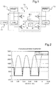
- the figure 1 recalls the conventional scheme of PWM pulse width modulation controlled inverter power generator 10, used to power a series-connected load at the output.
- the power generator 10 comprises a DC voltage source 11, which is for example made by rectifying a 230 V AC mains voltage and which supplies a regulated and adjustable DC supply voltage Vdc to an inverter 12.
- This inverter 12 has a four-switch bridge structure T1 to T4, such as IGBT (Insulated Gate Bipolar Transistor) power transistors, transistors T1-T3 and T2-T4, which form the two arms.
- a and B of the inverter 12 are connected in series between the two positive and negative terminals of the DC voltage source 11.
- the load for the power generator 10, comprises in particular an inductor referenced ID1, which can be likened to an inductance L1 connected in series with a capacity not shown, then forming a resonant circuit.
- the inductor ID1 is connected at the output of the inverter 12 between the two arms of switch A and B of the inverter 12, so that each of the terminals of the inductor ID1 is connected to the two positive and negative supply terminals of the DC voltage source 11 respectively by two transistors.
- the control circuit 13 by controlling the pass-blocking state of the transistors by an appropriate PWM command emitted via the control circuit 13, it is possible to impose the voltages across the inductor ID1, so as to obtain an alternating voltage V1.
- the AC voltage V1 delivered by the inverter 12 to the inductor ID1 makes it possible to generate a magnetic field used to induce a current in a secondary winding, not shown, of the receiver terminal installed in the vehicle, connected to a rectifying circuit. and filtering, for charging the battery.
- the load current absorbed by the inductor flows from the voltage applied to it.
- This current and the control of the transistors fix the supply current Idc of the inverter 12, that is to say the current called on the DC voltage source 11 of the inverter 12.
- the inverter 12 can be controlled by control signals having a PWM profile with a duty ratio of 0.5 and the control electrodes of two series transistors are oppositely controlled.
- a PWMA control signal drives the opening and closing of the transistor T1
- a control logic is designed to build the control signal of the transistor T3, inverting the PWMA signal and ensuring a dead time for avoid short circuiting the power supply of the inverter.
- a control signal PWMB which is the complement of the PWMA signal, controls the opening and closing of the transistor T2, while a logic The control circuit is designed to build the control signal of the transistor T4.
- the power transmitted to the load by the inverter 12 is a function, in particular, of the amplitude Vdc of the DC supply voltage E of the inverter 12, of the corrugated supply voltage V1 applied to the inductor ID1, and of the intensity I1 of the current flowing through the inductor ID1 at the output of the inverter 12.
- Vdc of the supply voltage E the power transmitted is maximum when the switching frequency is equal to the resonant frequency of the charge.
- the figure 2 illustrates the waveforms of the PWM control of the inverter for a duty cycle of 0.5 and the transmitted power P1, when at resonance.
- the transmitted power corresponds to a full-wave rectified sinus and the current flowing through the load has exactly the same speed as the power.
- the figure 3 illustrates the waveforms of the first and second control signals PWMA and PWMB respectively transmitted to the two switching arms of the inverter, which have a duty cycle of less than 0.5 (equal to 0.3 in the example shown) , and the voltage V1 applied at the output of the inverter, which results.
- the figure 4 then illustrates the PWMA control signal waveforms for a duty ratio of 0.3, superimposed on this same control signal for a duty cycle of 0.5, and the power transmitted to the load for this duty cycle of 0.3.
- the figure 5 illustrates a block diagram of a load control device for carrying out the method according to the invention.
- This device is implemented in the form of a computer 20 present at the ground transmitter terminal, having hardware and / or software for implementing the method of the invention.
- the system 30 to be regulated illustrated in FIG. figure 6 , consists of the power generator 10, comprising the DC power supply (voltage source 11) followed by the inverter 12, and the load connected in series with the output of the inverter 12, for a ground portion, consisting of by the inductor ID1 and for another part in a vehicle constituted by the receiving terminal.
- the load control device comprises a first regulation loop, according to a structure in which closed loop, the intensity of the supply current Idc of the inverter 12.
- This regulation is preferably effected by acting on the duty cycle of the control signals PWMA and WMB of the inverter 12.
- a current setpoint Imax_dc is calculated in the computer 20 from the maximum current value that can be supplied by the DC voltage source 11.
- the regulation loop of the supply current Idc thus makes it possible to limit this current to the maximum value that can be called on the DC voltage source.
- This regulation can for example be achieved by means of a corrector C1 (s).
- C1 corrector
- To set the regulation it is necessary to know the transfer function G (s) between the parameter ⁇ making it possible to modulate the duty cycle Rc of the control signals PWMA and PWMB of the inverter to a value other than 0.5 and the running Idc_mes.
- M be the gain modulation provided by a duty cycle other than 0.5.
- M is obtained by calculating the average value of the output current of the inverter, when it has the shape represented by the waveform illustrated in FIG. figure 2 .
- K p being the proportional gain and K i being the integral gain.
- the current Idc is imposed constant, equal to the maximum current that can be generated by the continuous supply of the inverter.
- equal in this application is meant “substantially equal”, the appreciation of the maximum current that can be generated by the power supply of the inverter may vary according to the estimation method of this value.
- the intensity of the supply current is regulated by adapting the duty cycle of the PWMA and PWMB control signals of the inverter as explained above, but the control signal PWMB is a signal complementary to that of the first control signal. PWMA.
- the inverter bridge 12 is controlled by two PWMA and PWMB control signals with cyclic ratios equal to 0.5, but the phase between the PWMA and PWMB control signals of the inverter 12 is varied, so that the supply current of the inverter is slaved to the reference Imax_dc.
- the ground computer 20 is adapted to receive from the battery supervision computer a power load request comprising a charge power setpoint P_cons corresponding to the power required.
- Pmax_dc Vdc_max x Imax_dc.
- the load control device further comprises a second closed-loop control loop of the power level actually injected by the inverter, acting simultaneously with the first control loop of the supply current Idc.
- the power setpoint P_cons comes from the battery supervision computer and this setpoint is for example determined according to the power level required in the context of the application of a strategy of end of charge of the battery. This setpoint is then compared with the power actually transmitted by the inverter, which is calculated from the values returned to the computer 20 by the continuous supply of the inverter, concerning the measured supply voltage Vdc_mes and the supply current. measured Idc_mes.
- the regulation can for example be carried out thanks to a corrector C2 (s), to ensure the fine control of the power transmitted.
- a corrector C2 (s) of type PI is synthesized and this synthesis is based on the knowledge of the transfer function T (s) between the measurement of the supply voltage of the inverter Vdc_mes and its control. Vdc_cons.
- the first corrector C1 (s) makes it possible to ensure the control of the power supply current of the inverter to the maximum value that can be supplied by the DC voltage source of the inverter power generator, while the second C2 corrector (s) ensures a fine regulation of the power injected by the inverter power generator.
- the load control device comprises a third regulation loop according to a closed-loop structure, acting simultaneously with the two regulation loops previously described, which aims to regulate the working frequency f of the inverter, so as to frequency slave the corrugated supply voltage V1 delivered by the inverter 12 at a frequency close to the resonant frequency of the output load of the inverter inverter.
- a third corrector C3 (s) of the PI type is synthesized and the phase difference between the corrugated supply voltage V1 and the corrugated supply current I1 is chosen as the adjustment parameter of this third regulation loop.
- output of the inverter 12 as a function of a phase difference setpoint Cons_Phase determined by the computer 20.
- control method of the invention makes it possible to simultaneously carry out 3 regulation functions by means of 3 correctors, which respectively make it possible to control the supply current, to inject exactly the desired power, even at low levels. medium and weak, and stay at the resonance of the system.
Landscapes
- Engineering & Computer Science (AREA)
- Power Engineering (AREA)
- Transportation (AREA)
- Mechanical Engineering (AREA)
- Computer Networks & Wireless Communication (AREA)
- Charge And Discharge Circuits For Batteries Or The Like (AREA)
- Electric Propulsion And Braking For Vehicles (AREA)
- Inverter Devices (AREA)
- Life Sciences & Earth Sciences (AREA)
- Chemical & Material Sciences (AREA)
- Combustion & Propulsion (AREA)
- Sustainable Energy (AREA)
- Sustainable Development (AREA)
Description
L'invention concerne un procédé de contrôle de charge d'une batterie d'un véhicule automobile à traction électrique ou hybride, dans un système de charge sans contact dans lequel un générateur de puissance, du type comportant une source de tension continue suivie d'un onduleur, alimente une charge comprenant un inducteur, connectée en série avec la sortie dudit onduleur, ledit procédé comportant une étape de pilotage dudit onduleur à une fréquence de travail asservie à une fréquence voisine de la fréquence de résonance de la charge en sortie dudit onduleur par transmission de premier et deuxième signaux de commande de modulation par largeur d'impulsion respectivement à des premier et deuxième bras de commutation dudit onduleur.The invention relates to a method for controlling the charge of a battery of an electric or hybrid traction motor vehicle in a non-contact charging system in which a power generator of the type comprising a DC voltage source followed by an inverter, supplying a load comprising an inductor, connected in series with the output of said inverter, said method comprising a step of controlling said inverter at a working frequency slaved to a frequency close to the resonant frequency of the load at the output of said inverter transmitting first and second pulse width modulation control signals respectively to first and second switching arms of said inverter.
Les systèmes de charge de batterie de véhicule automobile, dits « sans contact », sont bien connus et comprennent classiquement d'une part, agencée par exemple au sol d'une place de stationnement du véhicule, une borne émettrice d'énergie, comportant un inducteur alimenté par un générateur de puissance à onduleur relié au secteur et, d'autre part, agencée dans le véhicule, une borne réceptrice d'énergie, destinée à être placée au-dessus de l'inducteur, de façon à permettre un transfert d'énergie par couplage inductif entre l'inducteur et la borne réceptrice et à permettre ainsi la recharge de la batterie du véhicule.Vehicle battery charging systems, known as "non-contact" systems, are well known and conventionally comprise, on the one hand, arranged for example on the ground of a parking space of the vehicle, an energy-transmitting terminal comprising a an inductor fed by an inverter power generator connected to the mains and, on the other hand, arranged in the vehicle, an energy receiving terminal, intended to be placed above the inductor, so as to allow a transfer of energy. energy by inductive coupling between the inductor and the receiver terminal and thus allow the recharging of the vehicle battery.
L'intérêt de ces systèmes réside dans le confort et l'ergonomie d'utilisation en regard des systèmes de recharge filaire classiques. Toutefois, ces systèmes de charge sans contact ont l'inconvénient de nécessiter un positionnement très précis du véhicule relativement à la borne émettrice d'énergie, de manière à éviter une chute de rendement de la phase de charge de la batterie. Aussi, il a été envisagé dans le document
D'autres inconvénients demeurent toutefois. En particulier, les batteries haute tension utilisées pour alimenter les moteurs des véhicules à traction électrique disposent d'une impédance faible. Aussi, dans cette application, lorsqu'on est proche de la fréquence de résonance et que l'on cherche à recharger la batterie, l'impédance vue par le générateur de puissance devient très faible et, en conséquence, les courants appelés sur l'alimentation continue de l'onduleur deviennent très grands sans possibilité de les contrôler. Or, l'alimentation risque de passer quasi instantanément en saturation de courant, ce qui se traduit classiquement par un basculement en mode « défaut » de l'alimentation.However, other disadvantages remain. In particular, the high voltage batteries used to power the engines of electric vehicles have a low impedance. Also, in this application, when one is close to the resonant frequency and that one tries to recharge the battery, the impedance seen by the power generator becomes very weak and, consequently, the currents called on the UPS power supply become very large without the ability to control them. However, the power supply can go almost instantaneously in current saturation, which typically results in a switch to "default" mode of the power supply.
Le document
Dans ce contexte, la présente invention a pour but de proposer un procédé de contrôle de charge d'une batterie de véhicule électrique ou hybride, qui soit capable de réaliser un contrôle fin de la puissance injectée, tout en tenant compte des limitations réelles des alimentations disponibles.In this context, the present invention aims to propose a charge control method of an electric or hybrid vehicle battery, which is capable of performing a fine control of the injected power, while taking into account the actual limitations of the power supplies. available.
Dans ce but, le procédé de l'invention, par ailleurs conforme à la définition générique qu'en donne le préambule ci-dessus, est essentiellement caractérisé en ce qu'on réalise une régulation en boucle fermée de l'intensité du courant d'alimentation dudit onduleur, une consigne d'intensité du courant d'alimentation étant imposée constante, égale au courant maximal susceptible d'être fourni par ladite source de tension continue dudit onduleur, et on réalise simultanément une régulation en boucle fermée de la puissance transmise par ledit onduleur en agissant sur la commande de la tension d'alimentation dudit onduleur, une consigne de puissance étant établie en fonction d'une information de puissance électrique requise pour la charge de la batterie.For this purpose, the method of the invention, moreover in accordance with the generic definition given in the preamble above, is essentially characterized in that a closed-loop regulation of the intensity of the current is carried out. power supply of said inverter, a setpoint of the intensity of the supply current being imposed constant, equal to the maximum current likely to be supplied by said DC voltage source of said inverter, and a closed loop control of the power transmitted by said inverter acting on the control of the supply voltage of said inverter, a power setpoint being established according to a power information required for the charging of the battery.
De préférence, le procédé selon l'invention présente encore une ou plusieurs des caractéristiques suivantes :
- on mesure le courant parcourant la charge en sortie dudit onduleur, on compare le courant mesuré à ladite consigne de courant et on adapte les signaux de commande de modulation par largeur d'impulsion dudit onduleur si le courant mesuré diffère de la consigne, de sorte que le courant parcourant la charge en sorte dudit onduleur soit sensiblement égal à la consigne ;
- la régulation en boucle fermée de l'intensité du courant d'alimentation est réalisée en adaptant le rapport cyclique des premier et deuxième signaux de commande dudit onduleur ;
- le deuxième signal de commande dudit onduleur est un signal complémentaire à celui du premier signal de commande dudit onduleur ;
- la régulation en boucle fermée de l'intensité du courant d'alimentation est réalisée en faisant varier la phase entre les premier et deuxième signaux de commande dudit onduleur ;
- l'information de puissance électrique requise pour la charge de la batterie est transmise par un calculateur de supervision de la batterie en fonction d'une stratégie de fin de charge de la batterie ;
- l'asservissement de la fréquence de travail dudit onduleur à une fréquence voisine de la fréquence de résonance de ladite charge en sortie dudit onduleur consiste à réaliser une régulation en boucle fermée de la différence de phase entre la tension d'alimentation ondulée et le courant d'alimentation ondulé délivrés en sortie dudit onduleur, une consigne de différence de phase étant déterminée de manière à ce que la fréquence de travail dudit onduleur est imposée constante à une valeur sensiblement égale à celle de la fréquence de résonance de ladite charge en sortie.
- the current flowing through the load at the output of said inverter is measured, the measured current is compared with said current setpoint, and the pulse width modulation control signals of said inverter are adapted if the measured current differs from the setpoint, so that the current flowing through the load so that said inverter is substantially equal to the setpoint;
- the closed-loop regulation of the intensity of the supply current is carried out by adapting the duty cycle of the first and second control signals of said inverter;
- the second control signal of said inverter is a signal complementary to that of the first control signal of said inverter;
- the closed-loop regulation of the intensity of the supply current is carried out by varying the phase between the first and second control signals of said inverter;
- the electrical power information required for the charging of the battery is transmitted by a battery supervision computer according to a strategy of end of charge of the battery;
- the servocontrol of the operating frequency of said inverter at a frequency close to the resonant frequency of said load at the output of said inverter is to achieve a closed-loop regulation of the phase difference between the corrugated supply voltage and the current of the inverter. corrugated supply outputted from said inverter, a phase difference setpoint being determined so that the operating frequency of said inverter is imposed constant to a value substantially equal to that of the resonance frequency of said output load.
L'invention concerne aussi un calculateur comprenant des moyens matériels et/logiciels pour la mise en oeuvre du procédé selon l'invention.The invention also relates to a computer comprising hardware and software means for implementing the method according to the invention.
D'autres caractéristiques et avantages de l'invention ressortiront clairement de la description qui en est faite ci-après, à titre indicatif et nullement limitatif, en référence aux dessins annexés, dans lesquels:
- la
Figure 1 est une représentation schématique d'un générateur de puissance à onduleur mis en oeuvre dans un système de charge sans contact pour batterie de véhicule électrique ou hybride ; - la
Figure 2 est un schéma illustrant l'allure de la puissance injectée au niveau de la charge pour un rapport cyclique de 0,5 de la commande PWM des commutateurs de l'onduleur, lorsqu'on est à la résonance; - la
Figure 3 est un schéma illustrant les formes d'onde des premier et deuxième signaux de commande transmis respectivement aux deux bras de commutation de l'onduleur, avec un rapport cyclique égal à 0,3 selon l'exemple représenté, et de la tension résultante appliquée en sortie de l'onduleur ; - la
Figure 4 est un schéma illustrant l'allure de la puissance injectée pour un rapport cyclique de 0,3 de la commande PWM des commutateurs de l'onduleur ; - la
Figure 5 est un schéma synoptique d'un dispositif de contrôle de la charge pour la mise en oeuvre du procédé selon l'invention ; et - la
Figure 6 est un schéma illustrant le système à réguler auquel s'applique le procédé selon l'invention.
- the
Figure 1 is a schematic representation of an inverter power generator implemented in a non-contact charging system for an electric or hybrid vehicle battery; - the
Figure 2 is a diagram illustrating the shape of the power injected at the load for a duty ratio of 0.5 of the PWM control of the inverter switches, when at resonance; - the
Figure 3 is a diagram illustrating the waveforms of the first and second control signals respectively transmitted to the two switching arms of the inverter, with a duty cycle equal to 0.3 in the example shown, and the resulting voltage applied in output of the inverter; - the
Figure 4 is a diagram illustrating the shape of the injected power for a duty cycle of 0.3 of the PWM control of the inverter switches; - the
Figure 5 is a block diagram of a load control device for carrying out the method according to the invention; and - the
Figure 6 is a diagram illustrating the system to be regulated to which the method according to the invention applies.
La
La charge, pour le générateur de puissance 10, comprend notamment un inducteur référencé ID1, qui peut être assimilé à une inductance L1 montée en série avec une capacité non représentée, formant alors un circuit résonant. L'inducteur ID1 est raccordé en sortie de l'onduleur 12 entre les deux bras de commutation A et B de l'onduleur 12, de sorte que chacune des bornes de l'inducteur ID1 est reliée aux deux bornes d'alimentation positive et négative de la source de tension continue 11 respectivement par deux transistors. Pour régler la puissance absorbée par le circuit résonant en sortie de l'onduleur 12, on peut agir sur la fréquence de cycles successifs de conduction et de non conduction des transistors, par l'intermédiaire d'un circuit de commande 13 apte à générer des signaux de commande de type PWM à envoyer aux transistors permettant de commander essentiellement la fréquence, dite fréquence de travail de l'onduleur, à laquelle les transistors conduisent et se bloquent.The load, for the
Ainsi, en commandant l'état passant-bloquant des transistors par une commande PWM appropriée émise par l'intermédiaire du circuit de commande 13, on peut imposer les tensions aux bornes de l'inducteur ID1, de manière à obtenir une tension alternative V1. La tension alternative V1 délivrée par l'onduleur 12 à l'inducteur ID1 permet de générer un champ magnétique, utilisé pour induire un courant dans un enroulement secondaire, non représenté, de la borne réceptrice installée dans le véhicule, connecté à un circuit de redressement et de filtrage, pour la charge de la batterie. Le courant de charge absorbé par l'inducteur découle de la tension qui lui est appliquée. Ce courant et la commande des transistors fixent le courant d'alimentation Idc de l'onduleur 12, c'est-à-dire le courant appelé sur la source de tension continue 11 de l'onduleur 12.Thus, by controlling the pass-blocking state of the transistors by an appropriate PWM command emitted via the
L'onduleur 12 peut être commandé par des signaux de commande présentant un profil PWM de rapport cyclique égal à 0,5 et les électrodes de commande de deux transistors en série sont commandées en opposition. En particulier, un signal de commande PWMA pilote l'ouverture et la fermeture du transistor T1, tandis qu'une logique de commande est conçue pour construire le signal de commande du transistor T3, en inversant le signal PWMA et en assurant un temps mort pour éviter le court-circuit de la source d'alimentation de l'onduleur. De la même manière, s'agissant de la deuxième branche de l'onduleur 12, un signal de commande PWMB, qui est le complément du signal PWMA, pilote l'ouverture et la fermeture du transistor T2, tandis qu'une logique de commande est conçue pour construire le signal de commande du transistor T4.The
La puissance transmise à la charge par l'onduleur 12 est fonction notamment de l'amplitude Vdc de la tension continue d'alimentation E de l'onduleur 12, de la tension d'alimentation ondulée V1 appliquée à l'inducteur ID1 et de l'intensité I1 du courant parcourant l'inducteur ID1 en sortie de l'onduleur 12. Pour une amplitude Vdc de la tension d'alimentation E donnée, la puissance transmise est maximale quand la fréquence de commutation est égale à la fréquence de résonance de la charge. La
Les valeurs moyennes sont alors calculées de la manière suivante : ![]()
- Pmoy correspondant à la puissance ainsi transférée,
- Pcrête correspondant à la valeur maximale (valeur crête) de la puissance,
- Icrête correspondant à la valeur maximale du courant (valeur crête) et
- Imoy renvoyant à la valeur moyenne du courant d'alimentation Idc en sortie de la source de tension continue 11 de l'onduleur 12.
- P moy corresponding to the power thus transferred,
- P peak corresponding to the maximum value (peak value) of the power,
- I peak corresponding to the maximum value of the current (peak value) and
- I moy referring to the average value of the supply current Idc at the output of the
DC voltage source 11 of theinverter 12.
Conformément à l'invention, on prévoit de commander l'onduleur 12 avec des signaux de commande PWM non plus complémentés, mais ayant un rapport cyclique différent 0,5, afin d'agir sur le rapport entre les durées de conduction et de non conduction des transistors sur une période de travail, de sorte à n'injecter de la puissance électrique que pendant une fraction de la période.According to the invention, provision is made to control the
La
Aussi, pour une amplitude Vdc donnée de la tension d'alimentation E de l'onduleur 12, si celui-ci est commandé à l'aide de signaux de commande PWM dont le rapport cyclique vaut : ![]()
![]()
Alors, la puissance moyenne transmise à la charge, respectivement le courant appelé sur la source de tension continue de l'onduleur, i.e. le courant moyen parcourant la charge en sortie de l'onduleur, vaut cette fois : ![]()
![]()
On a donc un courant moyen appelé maîtrisé. L'application d'un rapport cyclique inférieur à 0,5 est donc équivalente à la mise en oeuvre d'un transformateur virtuel, qui diminuerait l'amplitude Vdc réellement appliquée de la tension d'alimentation de l'onduleur et donc, augmenterait le courant d'alimentation Idc du fait de la conservation de la puissance. Il est donc possible, en agissant sur le rapport cyclique des signaux de commande PWM de l'onduleur, de dépasser la limitation de courant de l'alimentation continue de l'onduleur et le rapport cyclique fournit ainsi une variable supplémentaire pour la commande du système en plus de l'amplitude Vdc de la tension d'alimentation E de l'onduleur.So we have an average current called mastered. The application of a duty cycle less than 0.5 is therefore equivalent to the implementation of a virtual transformer, which would reduce the amplitude Vdc actually applied to the supply voltage of the inverter and therefore, would increase the Idc power supply due to power conservation. It is therefore possible, by acting on the duty cycle of the PWM control signals of the inverter, to exceed the current limitation of the DC supply of the inverter and the duty cycle thus provides an additional variable for the control of the system. in addition to the amplitude Vdc of the supply voltage E of the inverter.
La
Ainsi, selon les principes exposés plus haut, le dispositif de contrôle de la charge comprend une première boucle de régulation, selon une structure en boucle fermée, de l'intensité du courant d'alimentation Idc de l'onduleur 12. Cette régulation est réalisée de préférence en agissant sur le rapport cyclique des signaux de commande PWMA et WMB de l'onduleur 12. A cette fin, l'alimentation continue de l'onduleur 12 est apte à transmettre au calculateur 20 une valeur mesurée Idc_mes de l'intensité du courant d'alimentation, correspondant à la valeur moyenne Idc_mod du courant ondulé parcourant la charge en sortie de l'onduleur, soit Idc_mod = Idc_mes. Une consigne de courant Imax_dc est calculée dans le calculateur 20 à partir de la valeur de courant maximal susceptible d'être fournie par la source de tension continue 11. La boucle de régulation du courant d'alimentation Idc permet ainsi de limiter ce courant à la valeur maximale qui peut être appelée sur la source de tension continue. Cette régulation peut par exemple être réalisée grâce à un correcteur C1 (s). Pour régler la régulation, il est nécessaire de connaître la fonction de transfert G(s) entre le paramètre α permettant de moduler le rapport cyclique Rc des signaux de commande PWMA et PWMB de l'onduleur à une valeur différente de 0,5 et le courant Idc_mes. Soit M, la modulation de gain apporté par un rapport cyclique différent de 0,5. M est obtenu en calculant la valeur moyenne du courant en sortie de l'onduleur, lorsqu'il a l'allure représentée par la forme d'onde illustrée à la 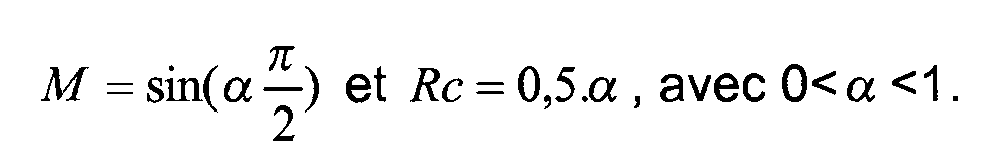
On néglige la dynamique entre α et la mesure de courant Idc_mes. La partie dynamique du transfert est imposée en ajoutant un filtre passe-bas F(s) sur la mesure de courant Idc_mes, de la forme : 
On choisit alors un correcteur de type PI de la forme : 
Kp étant le gain proportionnel et Ki étant le gain intégral.K p being the proportional gain and K i being the integral gain.
Ces gains sont réglés facilement dans la mesure où le système à contrôler a un gain connu (défini par M) et une dynamique connue (définie par F(s)). Les méthodes de calcul de Kp et Ki à partir de M et de F(s) sont alors bien connues par l'homme de l'art, puisqu'un calcul analytique est possibleThese gains are easily adjusted to the extent that the system to be controlled has a known gain (defined by M) and a known dynamic (defined by F (s)). The methods for calculating K p and K i from M and F (s) are then well known to those skilled in the art, since an analytical calculation is possible.
Ainsi, grâce à cette première boucle de régulation, le courant Idc est imposé constant, égal au courant maximum pouvant être généré par l'alimentation continue de l'onduleur. Par « égal » dans cette demande, on entend « sensiblement égal », l'appréciation du courant maximum pouvant être généré par l'alimentation de l'onduleur pouvant varier suivant la méthode d'estimation de cette valeur.Thus, thanks to this first regulation loop, the current Idc is imposed constant, equal to the maximum current that can be generated by the continuous supply of the inverter. By "equal" in this application is meant "substantially equal", the appreciation of the maximum current that can be generated by the power supply of the inverter may vary according to the estimation method of this value.
En variante, on régule l'intensité du courant d'alimentation en adaptant le rapport cyclique des signaux de commande PWMA et PWMB de l'onduleur comme expliqué précédemment, mais le signal de commande PWMB est un signal complémentaire à celui du premier signal de commande PWMA.In a variant, the intensity of the supply current is regulated by adapting the duty cycle of the PWMA and PWMB control signals of the inverter as explained above, but the control signal PWMB is a signal complementary to that of the first control signal. PWMA.
En variante encore, le pont onduleur 12 est commandé par deux signaux de commande PWMA et PWMB de rapports cycliques égaux à 0,5, mais on fait varier la phase entre les signaux de commande PWMA et PWMB de l'onduleur 12, de sorte que le courant d'alimentation de l'onduleur soit asservi à la consigne Imax_dc.In another variant, the
Par ailleurs, le calculateur au sol 20 est apte à recevoir du calculateur de supervision de la batterie une requête de charge en puissance comprenant une consigne de puissance de charge P_cons correspondant à la puissance requise. La première boucle de régulation du courant appelé sur l'alimentation continue de l'onduleur dont il est fait état plus haut recevant directement en entrée la valeur Imax_dc du courant maximal susceptible d'être fourni par la source de tension continue, il est possible de calculer une consigne de niveau de tension d'alimentation Vdc_cons à appliquer à l'onduleur, à partir de la puissance requise pour la charge de la batterie de la manière suivante : ![]()
![]()
Ce mode de contrôle permet de répondre efficacement à des puissances requises élevées, puisqu'il permet d'atteindre la puissance maximale pouvant être générée par la source de tension continue (Pmax_dc=Vdc_max x Imax_dc). En revanche, il est dans la pratique peu robuste, dans la mesure où il requiert que la boucle de régulation du courant d'alimentation Idc de l'onduleur fonctionne en permanence sans saturation. Or, notamment aux faibles valeurs de puissance, le courant Imax_dc peut ne pas être atteint. Par conséquent, un tel mode de régulation de la puissance n'est pas adapté pour mettre en oeuvre un contrôle fin de la puissance transmise par l'onduleur, en particulier aux faibles valeurs de puissance susceptibles d'être requises dans des stratégies de contrôle de fin de charge de la batterie.This control mode makes it possible to respond effectively to high power requirements, since it makes it possible to reach the maximum power that can be generated by the DC voltage source (Pmax_dc = Vdc_max x Imax_dc). On the other hand, it is in practice not robust, insofar as it requires that the control loop of the supply current Idc of the inverter operates permanently without saturation. However, particularly at low power values, the current Imax_dc may not be reached. Consequently, such a mode of power regulation is not suitable for carrying out a fine control of the power transmitted by the inverter, in particular at the low power values that may be required in control strategies. end of charge of the battery.
Aussi, le dispositif de contrôle de la charge comprend en outre une deuxième boucle de régulation en boucle fermée du niveau de puissance réellement injecté par l'onduleur, agissant simultanément avec la première boucle de régulation du courant d'alimentation Idc. La consigne de puissance P_cons provient du calculateur de supervision de la batterie et cette consigne est par exemple déterminée en fonction du niveau de puissance requis dans le cadre de l'application d'une stratégie de fin de charge de la batterie. Cette consigne est ensuite comparée à la puissance réellement transmise par l'onduleur, qui est calculée à partir des valeurs renvoyées au calculateur 20 par l'alimentation continue de l'onduleur, concernant la tension d'alimentation mesurée Vdc_mes et le courant d'alimentation mesuré Idc_mes.Also, the load control device further comprises a second closed-loop control loop of the power level actually injected by the inverter, acting simultaneously with the first control loop of the supply current Idc. The power setpoint P_cons comes from the battery supervision computer and this setpoint is for example determined according to the power level required in the context of the application of a strategy of end of charge of the battery. This setpoint is then compared with the power actually transmitted by the inverter, which is calculated from the values returned to the
La régulation peut par exemple être réalisée grâce à un correcteur C2(s), permettant d'assurer la régulation fine de la puissance transmise. Pour régler la régulation, on synthétise un deuxième correcteur C2(s) de type PI et cette synthèse repose sur la connaissance de la fonction de transfert T(s) entre la mesure de la tension d'alimentation de l'onduleur Vdc_mes et sa commande Vdc_cons.The regulation can for example be carried out thanks to a corrector C2 (s), to ensure the fine control of the power transmitted. To regulate the regulation, a second corrector C2 (s) of type PI is synthesized and this synthesis is based on the knowledge of the transfer function T (s) between the measurement of the supply voltage of the inverter Vdc_mes and its control. Vdc_cons.
Aussi, le premier correcteur C1(s) permet d'assurer le contrôle du courant d'alimentation de l'onduleur à la valeur maximale susceptible d'être fournie par la source de tension continue du générateur de puissance à onduleur, tandis que le deuxième correcteur C2(s) permet d'assurer une régulation fine de la puissance injectée par le générateur de puissance à onduleur.Also, the first corrector C1 (s) makes it possible to ensure the control of the power supply current of the inverter to the maximum value that can be supplied by the DC voltage source of the inverter power generator, while the second C2 corrector (s) ensures a fine regulation of the power injected by the inverter power generator.
Enfin, le dispositif de contrôle de la charge comprend une troisième boucle de régulation selon une structure en boucle fermée, agissant simultanément avec les deux boucles de régulation précédemment décrites, qui vise à réguler la fréquence de travail f de l'onduleur, de manière à asservir en fréquence la tension d'alimentation ondulée V1 délivrée par l'onduleur 12 à une fréquence voisine de la fréquence de résonance de la charge en sortie de l'onduleur. A cet effet, on synthétise un troisième correcteur C3(s) de type PI et on choisit comme paramètre de réglage de cette troisième boucle de régulation la différence de phase entre la tension d'alimentation ondulée V1 et le courant d'alimentation ondulé I1 en sortie de l'onduleur 12 en fonction d'une consigne de différence de phase Cons_Phase déterminé par le calculateur 20.Finally, the load control device comprises a third regulation loop according to a closed-loop structure, acting simultaneously with the two regulation loops previously described, which aims to regulate the working frequency f of the inverter, so as to frequency slave the corrugated supply voltage V1 delivered by the
Aussi, le procédé de contrôle de l'invention permet de réaliser simultanément 3 fonctions de régulation par l'intermédiaire de 3 correcteurs, qui permettent respectivement de contrôler le courant d'alimentation, d'injecter exactement la puissance souhaitée, y compris à des niveaux moyens et faibles, et de rester à la résonance du système.Also, the control method of the invention makes it possible to simultaneously carry out 3 regulation functions by means of 3 correctors, which respectively make it possible to control the supply current, to inject exactly the desired power, even at low levels. medium and weak, and stay at the resonance of the system.
Claims (9)
- Method for controlling the charging of a battery of an electric or hybrid drive motor vehicle in a non-contact charging system, wherein a power generator (10) of the type comprising a DC voltage source (11) followed by an inverter (12) feeds a load comprising an inductor (ID1), said load being connected in series with the output of said inverter (12), said method comprising a step of controlling said inverter (12) at a working frequency (f) slaved to a frequency close to the load resonance frequency at the output of said inverter (12) by transmission of first pulsewidth modulation command signal (PWMA) and a second pulsewidth modulation command signal (PWMB) to a first switching arm (A) and a second switching arm (B) respectively of said inverter (12), said method being characterized in that:- a closed-loop regulation of the intensity of the supply current of said inverter (12) is performed, a supply current intensity set value (Imax_dc) being fixed so as to be constant, equal to the maximum current able to be provided by said DC voltage source (11) of said inverter (12), and- a closed-loop regulation of the power transmitted by said inverter (12) is performed simultaneously by acting on the control of the supply voltage (Vdc_cons) of said inverter (12), a power set value (P_cons) being established according to a piece of electrical power information required for the charging of the battery.
- Method according to Claim 1, characterized in that the supply current (Idc_mes) passing through the load at the output of said inverter (12) is measured, the supply current measured (Idc_mes) is compared to said current set value (Imax_dc), and the pulsewidth modulation command signals (PWMA, PWMB) of said inverter (12) are adapted if the measured current (Idc_mes) differs from the set value (Imax_dc), such that the current passing through the load at the output of said inverter is substantially equal to the set value (Imax_dc).
- Method according to Claim 1 or 2, characterized in that the closed-loop regulation of the intensity of the supply current is performed by adapting the duty cycle of the first command signal (PWMA) and second command signal (PWMB) of said inverter (12).
- Method according to Claim 3, characterized in that the second command signal (PWMB) of said inverter (12) is a signal complementary to that of the first command signal (PWMA) of said inverter.
- Method according to Claim 1 or 2, characterized in that the closed-loop regulation of the intensity of the supply current is performed by varying the phase between the first command signal (PWMA) and the second command signal (PWMB) of said inverter (12).
- Method according to any one of the preceding claims, characterized in that said power set value (P_cons) is compared to the power actually transmitted by the inverter, said power actually transmitted being calculated on the basis of the measured values of the supply voltage (Vdc_mes) and of the supply current (Idc_mes).
- Method according to any one of the preceding claims, characterized in that the piece of electrical power information required for the charging of the battery is transmitted by a battery supervision computer according to a battery charging completion strategy.
- Method according to any one of the preceding claims, characterized in that the enslavement of the working frequency (f) of said inverter (12) to a frequency close to the resonance frequency of said load at the output of said inverter (12) consists of performing a closed-loop regulation of the phase difference between the ripple supply voltage (V1) and the ripple supply current (I1) delivered at the output of said inverter (12), a phase difference set value (Cons_phase) being determined in such a way that the working frequency of said inverter (12) is fixed so as to be constant at a value substantially equal to that of the resonance frequency of said load at the output.
- Computer (20), characterized in that it comprises hardware and/or software means for carrying out the method according to any one of the preceding claims.
Applications Claiming Priority (2)
| Application Number | Priority Date | Filing Date | Title |
|---|---|---|---|
| FR1255825A FR2992492B1 (en) | 2012-06-21 | 2012-06-21 | METHOD FOR CONTROLLING CHARGE OF A BATTERY OF AN ELECTRIC VEHICLE IN A CONTACTLESS LOADING SYSTEM |
| PCT/FR2013/051344 WO2013190215A1 (en) | 2012-06-21 | 2013-06-11 | Method for controlling the charging of a battery of an electric vehicle in a non-contact charging system |
Publications (2)
| Publication Number | Publication Date |
|---|---|
| EP2864150A1 EP2864150A1 (en) | 2015-04-29 |
| EP2864150B1 true EP2864150B1 (en) | 2016-04-27 |
Family
ID=46852190
Family Applications (1)
| Application Number | Title | Priority Date | Filing Date |
|---|---|---|---|
| EP13733384.5A Active EP2864150B1 (en) | 2012-06-21 | 2013-06-11 | Method for controlling the charging of a battery of an electric vehicle in a non-contact charging system |
Country Status (6)
| Country | Link |
|---|---|
| US (1) | US20150239353A1 (en) |
| EP (1) | EP2864150B1 (en) |
| JP (1) | JP2015532080A (en) |
| KR (1) | KR102097130B1 (en) |
| FR (1) | FR2992492B1 (en) |
| WO (1) | WO2013190215A1 (en) |
Families Citing this family (15)
| Publication number | Priority date | Publication date | Assignee | Title |
|---|---|---|---|---|
| WO2013003804A2 (en) | 2011-06-30 | 2013-01-03 | Lutron Electronics Co., Inc. | Method for programming a load control device using a smart phone |
| US9386666B2 (en) | 2011-06-30 | 2016-07-05 | Lutron Electronics Co., Inc. | Method of optically transmitting digital information from a smart phone to a control device |
| US10271407B2 (en) | 2011-06-30 | 2019-04-23 | Lutron Electronics Co., Inc. | Load control device having Internet connectivity |
| WO2013033263A1 (en) | 2011-08-29 | 2013-03-07 | Lutron Electronics Co., Inc. | Two-part load control system mountable to a single electrical wallbox |
| US10244086B2 (en) | 2012-12-21 | 2019-03-26 | Lutron Electronics Co., Inc. | Multiple network access load control devices |
| US10019047B2 (en) | 2012-12-21 | 2018-07-10 | Lutron Electronics Co., Inc. | Operational coordination of load control devices for control of electrical loads |
| US9413171B2 (en) | 2012-12-21 | 2016-08-09 | Lutron Electronics Co., Inc. | Network access coordination of load control devices |
| US10411763B2 (en) * | 2015-02-09 | 2019-09-10 | Tyco Electronics (Shanghai) Co. Ltd. | Wireless power transmission device |
| CN204578220U (en) * | 2015-02-09 | 2015-08-19 | 泰科电子(上海)有限公司 | Contactless power transmission device and the equipment comprising Contactless power transmission device |
| FR3038152B1 (en) * | 2015-06-24 | 2018-07-06 | Valeo Siemens Eautomotive France Sas | METHOD FOR CHARGING AN ELECTRIC ENERGY STORAGE UNIT AND VOLTAGE CONVERTER |
| CN105258721A (en) * | 2015-11-04 | 2016-01-20 | 广州杰赛科技股份有限公司 | Spherical detection device and motor driving method |
| FR3043505B1 (en) * | 2015-11-09 | 2017-11-03 | Renault Sas | METHOD FOR NON-CONTACTLY CHARGING A BATTERY OF A MOTOR VEHICLE IN MOTION, AND CORRESPONDING SYSTEM |
| FR3081266B1 (en) * | 2018-05-16 | 2022-05-20 | Renault Sas | SYSTEM AND METHOD FOR CONTACTLESS ELECTRICAL POWER TRANSFER BETWEEN A GROUND FIXED DEVICE AND A VEHICLE |
| CN109774530B (en) * | 2019-01-22 | 2021-09-21 | 江苏中天互联科技有限公司 | Charging pile and intelligent power allocation method thereof |
| US11420523B2 (en) * | 2020-09-25 | 2022-08-23 | GM Global Technology Operations LLC | Enhanced electric drive vehicle operation via pulse width modulation (PWM) type and frequency control |
Family Cites Families (6)
| Publication number | Priority date | Publication date | Assignee | Title |
|---|---|---|---|---|
| JP3227480B2 (en) * | 1996-05-29 | 2001-11-12 | シャープ株式会社 | Inverter device islanding operation detection method and inverter device |
| US6160374A (en) * | 1999-08-02 | 2000-12-12 | General Motors Corporation | Power-factor-corrected single-stage inductive charger |
| US6888263B2 (en) * | 2001-05-23 | 2005-05-03 | Ebara Corporation | Gas turbine generator |
| WO2010062198A1 (en) * | 2008-11-26 | 2010-06-03 | Auckland Uniservices Limited | Bi-directional inductive power transfer |
| US10355526B2 (en) * | 2008-11-26 | 2019-07-16 | Auckland Uniservices Limited | Bi-directional inductive power transfer |
| JP5369693B2 (en) * | 2009-01-15 | 2013-12-18 | 日産自動車株式会社 | Non-contact power feeding device |
-
2012
- 2012-06-21 FR FR1255825A patent/FR2992492B1/en not_active Expired - Fee Related
-
2013
- 2013-06-11 EP EP13733384.5A patent/EP2864150B1/en active Active
- 2013-06-11 KR KR1020157000471A patent/KR102097130B1/en active IP Right Grant
- 2013-06-11 WO PCT/FR2013/051344 patent/WO2013190215A1/en active Application Filing
- 2013-06-11 JP JP2015517823A patent/JP2015532080A/en active Pending
- 2013-06-11 US US14/409,775 patent/US20150239353A1/en not_active Abandoned
Also Published As
| Publication number | Publication date |
|---|---|
| FR2992492A1 (en) | 2013-12-27 |
| WO2013190215A1 (en) | 2013-12-27 |
| JP2015532080A (en) | 2015-11-05 |
| US20150239353A1 (en) | 2015-08-27 |
| KR20150028809A (en) | 2015-03-16 |
| KR102097130B1 (en) | 2020-04-03 |
| EP2864150A1 (en) | 2015-04-29 |
| FR2992492B1 (en) | 2015-12-11 |
Similar Documents
| Publication | Publication Date | Title |
|---|---|---|
| EP2864150B1 (en) | Method for controlling the charging of a battery of an electric vehicle in a non-contact charging system | |
| EP2408087B1 (en) | Method for controlling switching arm switches, in particular for loading accumulation resources, and the corresponding loading device | |
| FR2944653A1 (en) | MOTOR VEHICLE WITH ELECTRIC PROPULSION AND CHARGE TERMINAL OF THE BATTERY OF SUCH A VEHICLE | |
| EP2823554B1 (en) | Charging device for a vehicle battery comprising an ac-dc converter with a resonant isolated stage | |
| EP3639355A1 (en) | Method for controlling a three-phase vienna rectifier | |
| FR3064848A1 (en) | METHOD FOR CONTROLLING AN ON-BOARD CHARGING DEVICE ON AN ELECTRIC OR HYBRID VEHICLE | |
| EP3183795B1 (en) | Battery charger for high-integration electric or hybrid motor vehicle | |
| FR3096847A1 (en) | Method of controlling a DC-DC converter for a bidirectional electric storage battery charger | |
| EP3221181B1 (en) | Method for recharging energy accumulation means fitted to an electric or hybrid vehicle | |
| EP3520210B1 (en) | Method for controlling a three-phase rectifier for a charging device on board an electrical or hybrid vehicle | |
| EP3539204B1 (en) | Method for controlling a three-phase rectifier for a charging device on board an electric or hybrid vehicle | |
| EP2421117B1 (en) | Method for controlling switching arm switches, in particular for loading accumulation resources, and the corresponding loading device | |
| EP3171505B1 (en) | Device for charging a traction battery of a motor vehicle with at least partially electric traction | |
| FR3026243A1 (en) | DEVICE AND METHOD FOR CHARGING A BATTERY AND SUPPLYING A CONTINUOUS-CONTINUOUS CONVERTER ELECTRICAL MACHINE | |
| EP3707800B1 (en) | Method for controlling a battery charger for electrical accumulators | |
| EP3539203B1 (en) | Method for controlling a three-phase rectifier for a charging device on board an electrical or hybrid vehicle | |
| FR3082680A1 (en) | METHOD FOR FREQUENCY CONTROL OF THE INPUT VOLTAGE OF A DIRECT CURRENT-DIRECT CURRENT CONVERTER | |
| FR3056853B1 (en) | METHOD FOR CONTROLLING A THREE-PHASE RECTIFIER FOR AN ON-BOARD CHARGING DEVICE ON AN ELECTRIC OR HYBRID VEHICLE | |
| FR3077441A1 (en) | METHOD FOR CONTROLLING A THREE PHASE RECTIFIER FOR A THREE - PHASE INPUT CHARGING DEVICE. | |
| FR3123515A1 (en) | Electric power supply system for at least one electric traction machine of a motor vehicle supplied by at least two power sources. | |
| FR2983365A1 (en) | Power supply system for supplying power to battery of electric car, has transistor modulating current intensity of inductor coil so that average value of modulated current intensity is equal to value of reference current | |
| FR3026580A1 (en) | METHOD FOR CONTROLLING A RECTIFIER STAGE OF A CHARGE SYSTEM AND CORRESPONDING CHARGE SYSTEM |
Legal Events
| Date | Code | Title | Description |
|---|---|---|---|
| PUAI | Public reference made under article 153(3) epc to a published international application that has entered the european phase |
Free format text: ORIGINAL CODE: 0009012 |
|
| 17P | Request for examination filed |
Effective date: 20141127 |
|
| AK | Designated contracting states |
Kind code of ref document: A1 Designated state(s): AL AT BE BG CH CY CZ DE DK EE ES FI FR GB GR HR HU IE IS IT LI LT LU LV MC MK MT NL NO PL PT RO RS SE SI SK SM TR |
|
| AX | Request for extension of the european patent |
Extension state: BA ME |
|
| DAX | Request for extension of the european patent (deleted) | ||
| REG | Reference to a national code |
Ref country code: DE Ref legal event code: R079 Ref document number: 602013007106 Country of ref document: DE Free format text: PREVIOUS MAIN CLASS: B60L0011180000 Ipc: H02J0007000000 |
|
| GRAP | Despatch of communication of intention to grant a patent |
Free format text: ORIGINAL CODE: EPIDOSNIGR1 |
|
| RIC1 | Information provided on ipc code assigned before grant |
Ipc: B60L 11/18 20060101ALI20151030BHEP Ipc: H02J 7/00 20060101AFI20151030BHEP |
|
| INTG | Intention to grant announced |
Effective date: 20151208 |
|
| GRAS | Grant fee paid |
Free format text: ORIGINAL CODE: EPIDOSNIGR3 |
|
| GRAA | (expected) grant |
Free format text: ORIGINAL CODE: 0009210 |
|
| AK | Designated contracting states |
Kind code of ref document: B1 Designated state(s): AL AT BE BG CH CY CZ DE DK EE ES FI FR GB GR HR HU IE IS IT LI LT LU LV MC MK MT NL NO PL PT RO RS SE SI SK SM TR |
|
| REG | Reference to a national code |
Ref country code: GB Ref legal event code: FG4D Free format text: NOT ENGLISH |
|
| REG | Reference to a national code |
Ref country code: CH Ref legal event code: EP |
|
| REG | Reference to a national code |
Ref country code: AT Ref legal event code: REF Ref document number: 795749 Country of ref document: AT Kind code of ref document: T Effective date: 20160515 |
|
| REG | Reference to a national code |
Ref country code: IE Ref legal event code: FG4D Free format text: LANGUAGE OF EP DOCUMENT: FRENCH |
|
| REG | Reference to a national code |
Ref country code: DE Ref legal event code: R096 Ref document number: 602013007106 Country of ref document: DE |
|
| REG | Reference to a national code |
Ref country code: FR Ref legal event code: PLFP Year of fee payment: 4 |
|
| REG | Reference to a national code |
Ref country code: LT Ref legal event code: MG4D |
|
| REG | Reference to a national code |
Ref country code: NL Ref legal event code: MP Effective date: 20160427 |
|
| REG | Reference to a national code |
Ref country code: AT Ref legal event code: MK05 Ref document number: 795749 Country of ref document: AT Kind code of ref document: T Effective date: 20160427 |
|
| REG | Reference to a national code |
Ref country code: NO Ref legal event code: T2 Effective date: 20160427 |
|
| PG25 | Lapsed in a contracting state [announced via postgrant information from national office to epo] |
Ref country code: NL Free format text: LAPSE BECAUSE OF FAILURE TO SUBMIT A TRANSLATION OF THE DESCRIPTION OR TO PAY THE FEE WITHIN THE PRESCRIBED TIME-LIMIT Effective date: 20160427 |
|
| PG25 | Lapsed in a contracting state [announced via postgrant information from national office to epo] |
Ref country code: LT Free format text: LAPSE BECAUSE OF FAILURE TO SUBMIT A TRANSLATION OF THE DESCRIPTION OR TO PAY THE FEE WITHIN THE PRESCRIBED TIME-LIMIT Effective date: 20160427 Ref country code: PL Free format text: LAPSE BECAUSE OF FAILURE TO SUBMIT A TRANSLATION OF THE DESCRIPTION OR TO PAY THE FEE WITHIN THE PRESCRIBED TIME-LIMIT Effective date: 20160427 Ref country code: FI Free format text: LAPSE BECAUSE OF FAILURE TO SUBMIT A TRANSLATION OF THE DESCRIPTION OR TO PAY THE FEE WITHIN THE PRESCRIBED TIME-LIMIT Effective date: 20160427 |
|
| PG25 | Lapsed in a contracting state [announced via postgrant information from national office to epo] |
Ref country code: ES Free format text: LAPSE BECAUSE OF FAILURE TO SUBMIT A TRANSLATION OF THE DESCRIPTION OR TO PAY THE FEE WITHIN THE PRESCRIBED TIME-LIMIT Effective date: 20160427 Ref country code: LV Free format text: LAPSE BECAUSE OF FAILURE TO SUBMIT A TRANSLATION OF THE DESCRIPTION OR TO PAY THE FEE WITHIN THE PRESCRIBED TIME-LIMIT Effective date: 20160427 Ref country code: RS Free format text: LAPSE BECAUSE OF FAILURE TO SUBMIT A TRANSLATION OF THE DESCRIPTION OR TO PAY THE FEE WITHIN THE PRESCRIBED TIME-LIMIT Effective date: 20160427 Ref country code: HR Free format text: LAPSE BECAUSE OF FAILURE TO SUBMIT A TRANSLATION OF THE DESCRIPTION OR TO PAY THE FEE WITHIN THE PRESCRIBED TIME-LIMIT Effective date: 20160427 Ref country code: PT Free format text: LAPSE BECAUSE OF FAILURE TO SUBMIT A TRANSLATION OF THE DESCRIPTION OR TO PAY THE FEE WITHIN THE PRESCRIBED TIME-LIMIT Effective date: 20160829 Ref country code: AT Free format text: LAPSE BECAUSE OF FAILURE TO SUBMIT A TRANSLATION OF THE DESCRIPTION OR TO PAY THE FEE WITHIN THE PRESCRIBED TIME-LIMIT Effective date: 20160427 Ref country code: SE Free format text: LAPSE BECAUSE OF FAILURE TO SUBMIT A TRANSLATION OF THE DESCRIPTION OR TO PAY THE FEE WITHIN THE PRESCRIBED TIME-LIMIT Effective date: 20160427 Ref country code: GR Free format text: LAPSE BECAUSE OF FAILURE TO SUBMIT A TRANSLATION OF THE DESCRIPTION OR TO PAY THE FEE WITHIN THE PRESCRIBED TIME-LIMIT Effective date: 20160728 |
|
| PG25 | Lapsed in a contracting state [announced via postgrant information from national office to epo] |
Ref country code: IT Free format text: LAPSE BECAUSE OF FAILURE TO SUBMIT A TRANSLATION OF THE DESCRIPTION OR TO PAY THE FEE WITHIN THE PRESCRIBED TIME-LIMIT Effective date: 20160427 Ref country code: BE Free format text: LAPSE BECAUSE OF NON-PAYMENT OF DUE FEES Effective date: 20160630 |
|
| REG | Reference to a national code |
Ref country code: DE Ref legal event code: R097 Ref document number: 602013007106 Country of ref document: DE |
|
| PG25 | Lapsed in a contracting state [announced via postgrant information from national office to epo] |
Ref country code: MC Free format text: LAPSE BECAUSE OF FAILURE TO SUBMIT A TRANSLATION OF THE DESCRIPTION OR TO PAY THE FEE WITHIN THE PRESCRIBED TIME-LIMIT Effective date: 20160427 Ref country code: CZ Free format text: LAPSE BECAUSE OF FAILURE TO SUBMIT A TRANSLATION OF THE DESCRIPTION OR TO PAY THE FEE WITHIN THE PRESCRIBED TIME-LIMIT Effective date: 20160427 Ref country code: SK Free format text: LAPSE BECAUSE OF FAILURE TO SUBMIT A TRANSLATION OF THE DESCRIPTION OR TO PAY THE FEE WITHIN THE PRESCRIBED TIME-LIMIT Effective date: 20160427 Ref country code: DK Free format text: LAPSE BECAUSE OF FAILURE TO SUBMIT A TRANSLATION OF THE DESCRIPTION OR TO PAY THE FEE WITHIN THE PRESCRIBED TIME-LIMIT Effective date: 20160427 Ref country code: EE Free format text: LAPSE BECAUSE OF FAILURE TO SUBMIT A TRANSLATION OF THE DESCRIPTION OR TO PAY THE FEE WITHIN THE PRESCRIBED TIME-LIMIT Effective date: 20160427 Ref country code: RO Free format text: LAPSE BECAUSE OF FAILURE TO SUBMIT A TRANSLATION OF THE DESCRIPTION OR TO PAY THE FEE WITHIN THE PRESCRIBED TIME-LIMIT Effective date: 20160427 |
|
| REG | Reference to a national code |
Ref country code: CH Ref legal event code: PL |
|
| PG25 | Lapsed in a contracting state [announced via postgrant information from national office to epo] |
Ref country code: SM Free format text: LAPSE BECAUSE OF FAILURE TO SUBMIT A TRANSLATION OF THE DESCRIPTION OR TO PAY THE FEE WITHIN THE PRESCRIBED TIME-LIMIT Effective date: 20160427 |
|
| PLBE | No opposition filed within time limit |
Free format text: ORIGINAL CODE: 0009261 |
|
| STAA | Information on the status of an ep patent application or granted ep patent |
Free format text: STATUS: NO OPPOSITION FILED WITHIN TIME LIMIT |
|
| REG | Reference to a national code |
Ref country code: IE Ref legal event code: MM4A |
|
| 26N | No opposition filed |
Effective date: 20170130 |
|
| PG25 | Lapsed in a contracting state [announced via postgrant information from national office to epo] |
Ref country code: LI Free format text: LAPSE BECAUSE OF NON-PAYMENT OF DUE FEES Effective date: 20160630 Ref country code: CH Free format text: LAPSE BECAUSE OF NON-PAYMENT OF DUE FEES Effective date: 20160630 |
|
| PG25 | Lapsed in a contracting state [announced via postgrant information from national office to epo] |
Ref country code: SI Free format text: LAPSE BECAUSE OF FAILURE TO SUBMIT A TRANSLATION OF THE DESCRIPTION OR TO PAY THE FEE WITHIN THE PRESCRIBED TIME-LIMIT Effective date: 20160427 Ref country code: IE Free format text: LAPSE BECAUSE OF NON-PAYMENT OF DUE FEES Effective date: 20160611 |
|
| REG | Reference to a national code |
Ref country code: FR Ref legal event code: PLFP Year of fee payment: 5 |
|
| PG25 | Lapsed in a contracting state [announced via postgrant information from national office to epo] |
Ref country code: HU Free format text: LAPSE BECAUSE OF FAILURE TO SUBMIT A TRANSLATION OF THE DESCRIPTION OR TO PAY THE FEE WITHIN THE PRESCRIBED TIME-LIMIT; INVALID AB INITIO Effective date: 20130611 |
|
| REG | Reference to a national code |
Ref country code: FR Ref legal event code: PLFP Year of fee payment: 6 |
|
| PG25 | Lapsed in a contracting state [announced via postgrant information from national office to epo] |
Ref country code: MT Free format text: LAPSE BECAUSE OF FAILURE TO SUBMIT A TRANSLATION OF THE DESCRIPTION OR TO PAY THE FEE WITHIN THE PRESCRIBED TIME-LIMIT Effective date: 20160427 Ref country code: LU Free format text: LAPSE BECAUSE OF NON-PAYMENT OF DUE FEES Effective date: 20160611 Ref country code: CY Free format text: LAPSE BECAUSE OF FAILURE TO SUBMIT A TRANSLATION OF THE DESCRIPTION OR TO PAY THE FEE WITHIN THE PRESCRIBED TIME-LIMIT Effective date: 20160427 Ref country code: MK Free format text: LAPSE BECAUSE OF FAILURE TO SUBMIT A TRANSLATION OF THE DESCRIPTION OR TO PAY THE FEE WITHIN THE PRESCRIBED TIME-LIMIT Effective date: 20160427 Ref country code: IS Free format text: LAPSE BECAUSE OF FAILURE TO SUBMIT A TRANSLATION OF THE DESCRIPTION OR TO PAY THE FEE WITHIN THE PRESCRIBED TIME-LIMIT Effective date: 20160427 |
|
| PG25 | Lapsed in a contracting state [announced via postgrant information from national office to epo] |
Ref country code: BG Free format text: LAPSE BECAUSE OF FAILURE TO SUBMIT A TRANSLATION OF THE DESCRIPTION OR TO PAY THE FEE WITHIN THE PRESCRIBED TIME-LIMIT Effective date: 20160427 |
|
| PG25 | Lapsed in a contracting state [announced via postgrant information from national office to epo] |
Ref country code: AL Free format text: LAPSE BECAUSE OF FAILURE TO SUBMIT A TRANSLATION OF THE DESCRIPTION OR TO PAY THE FEE WITHIN THE PRESCRIBED TIME-LIMIT Effective date: 20160427 Ref country code: TR Free format text: LAPSE BECAUSE OF FAILURE TO SUBMIT A TRANSLATION OF THE DESCRIPTION OR TO PAY THE FEE WITHIN THE PRESCRIBED TIME-LIMIT Effective date: 20160427 |
|
| P01 | Opt-out of the competence of the unified patent court (upc) registered |
Effective date: 20230608 |
|
| PGFP | Annual fee paid to national office [announced via postgrant information from national office to epo] |
Ref country code: NO Payment date: 20230622 Year of fee payment: 11 |
|
| PGFP | Annual fee paid to national office [announced via postgrant information from national office to epo] |
Ref country code: GB Payment date: 20230622 Year of fee payment: 11 |
|
| PGFP | Annual fee paid to national office [announced via postgrant information from national office to epo] |
Ref country code: DE Payment date: 20240619 Year of fee payment: 12 |
|
| REG | Reference to a national code |
Ref country code: DE Ref legal event code: R081 Ref document number: 602013007106 Country of ref document: DE Owner name: AMPERE S.A.S., FR Free format text: FORMER OWNER: RENAULT S.A.S., BOULOGNE-BILLANCOURT, FR |
|
| PGFP | Annual fee paid to national office [announced via postgrant information from national office to epo] |
Ref country code: FR Payment date: 20240628 Year of fee payment: 12 |