EP2863723A2 - Device management module, remote management module and device management system employing same - Google Patents
Device management module, remote management module and device management system employing same Download PDFInfo
- Publication number
- EP2863723A2 EP2863723A2 EP20140161693 EP14161693A EP2863723A2 EP 2863723 A2 EP2863723 A2 EP 2863723A2 EP 20140161693 EP20140161693 EP 20140161693 EP 14161693 A EP14161693 A EP 14161693A EP 2863723 A2 EP2863723 A2 EP 2863723A2
- Authority
- EP
- European Patent Office
- Prior art keywords
- remotely
- controllable switching
- switching circuit
- circuit
- management unit
- Prior art date
- Legal status (The legal status is an assumption and is not a legal conclusion. Google has not performed a legal analysis and makes no representation as to the accuracy of the status listed.)
- Granted
Links
Images




Classifications
-
- H—ELECTRICITY
- H05—ELECTRIC TECHNIQUES NOT OTHERWISE PROVIDED FOR
- H05K—PRINTED CIRCUITS; CASINGS OR CONSTRUCTIONAL DETAILS OF ELECTRIC APPARATUS; MANUFACTURE OF ASSEMBLAGES OF ELECTRICAL COMPONENTS
- H05K7/00—Constructional details common to different types of electric apparatus
- H05K7/14—Mounting supporting structure in casing or on frame or rack
- H05K7/1485—Servers; Data center rooms, e.g. 19-inch computer racks
- H05K7/1488—Cabinets therefor, e.g. chassis or racks or mechanical interfaces between blades and support structures
- H05K7/1492—Cabinets therefor, e.g. chassis or racks or mechanical interfaces between blades and support structures having electrical distribution arrangements, e.g. power supply or data communications
-
- G—PHYSICS
- G08—SIGNALLING
- G08B—SIGNALLING SYSTEMS, e.g. PERSONAL CALLING SYSTEMS; ORDER TELEGRAPHS; ALARM SYSTEMS
- G08B21/00—Alarms responsive to a single specified undesired or abnormal condition and not otherwise provided for
- G08B21/18—Status alarms
- G08B21/182—Level alarms, e.g. alarms responsive to variables exceeding a threshold
-
- H—ELECTRICITY
- H05—ELECTRIC TECHNIQUES NOT OTHERWISE PROVIDED FOR
- H05K—PRINTED CIRCUITS; CASINGS OR CONSTRUCTIONAL DETAILS OF ELECTRIC APPARATUS; MANUFACTURE OF ASSEMBLAGES OF ELECTRICAL COMPONENTS
- H05K7/00—Constructional details common to different types of electric apparatus
- H05K7/14—Mounting supporting structure in casing or on frame or rack
- H05K7/1485—Servers; Data center rooms, e.g. 19-inch computer racks
- H05K7/1498—Resource management, Optimisation arrangements, e.g. configuration, identification, tracking, physical location
Definitions
- a data center is a facility used to house computers or servers. For providing intensive network applications, the number of computers or servers of the data center is gradually increased.
- a plurality of devices are accommodated within a rack cabinet of the data center in a hot-swappable manner.
- the data center may comprise a plurality of rack cabinets.
- the number of devices within the data center is increased. Consequently, power supply, power distribution and power management become important issues.
- a power distribution unit is used to distribute power among the devices.
- the AC power When AC power (e.g. utility power) is received by the rack cabinet, the AC power is transmitted from the power distribution unit to all devices within the rack cabinet. Each device has a power supply unit for receiving the AC power and converting the AC power into DC power, thereby powering circuitry of the device. Moreover, if one of the devices within the rack cabinet is suffered from breakdown or shutdown, the power distribution unit is responsible for stopping providing power to all devices within the rack cabinet. Consequently, the device which is suffered from breakdown or shutdown may be resumed.
- AC power e.g. utility power
- the device since the device has the power supply unit, the volume of the device is relatively bulky. Moreover, since the inner space of the rack cabinet is limited, the number of devices accommodated within the rack cabinet is restricted by the volume of the device. Moreover, since the power supply unit is disposed within the device, the heat-dissipating efficacy is usually unsatisfied. Moreover, if any device within the rack cabinet is suffered from breakdown or shutdown, it is necessary to stop the power distribution unit from providing electric power to all devices of the rack cabinet. In other words, the electric power to the device which is suffered from breakdown or shutdown cannot be stopped individually. Under this circumstance, the utilization flexible of the rack cabinet is impaired.
- the worker has to move the data center to successively check all devices of the rack cabinet. After the device which is suffered from breakdown or shutdown is searched, the user may start repairing or resuming the device. In other words, the way of maintaining or resuming the device of the rack cabinet is time-consuming and labor-intensive.
- a power shelf is installed in the rack cabinet and the power distribution unit is omitted.
- the power shelf is used for converting AC power into DC power and transmitting the DC power to all devices of the rack cabinet. Under this circumstance, it is not necessary to install the power supply unit in each device. Consequently, the volume of the device is reduced, and the heat-dissipating efficacy of the device is enhanced. Since the power shelf does not have the function of controlling power to one or more devices, if the device within the rack cabinet is suffered from breakdown or shutdown, the user may manually remove the device which is suffered from breakdown or shutdown and resume the device. Similarly, the way of maintaining or resuming the device of the rack cabinet is time-consuming and labor-intensive.
- the present invention provides a device management module, a remote management module and a device management system.
- the device management system uses the device management module and the remote management module to individually and remotely control the devices within the rack cabinet. If any device within the rack cabinet is suffered from breakdown or shutdown, according to a command from the remote management module, a switch element of a remotely-controllable switching circuit is controlled to be in an off state. Since the switch element is turned off, the DC power is no longer received by the device which is suffered from breakdown or shutdown. Consequently, the purpose of resuming the device is achieved. In comparison with the conventional method of manually resuming the device, the use of the device management system of the present invention is time-saving and labor-saving.
- the present invention provides a device management system for monitoring all devices of the rack cabinet and storing and analyzing real-time data of the devices, thereby providing the information about the maintenance and the life of the device.
- a device management system for managing at least one hot-swappable device within a rack cabinet.
- the device management system includes a bus bar, a device management module, and a remote management module.
- the bus bar is used for transferring signals and DC power.
- the device management module is used for monitoring whether the device is installed in the rack cabinet and collecting information of the device which is installed in the rack cabinet.
- the device management module includes at least one remotely-controllable switching circuit and a detecting circuit.
- the remotely-controllable switching circuit is installed in an installation block. A first end of the remotely-controllable switching circuit is connected with the bus bar. A second end of the remotely-controllable switching circuit is connected with the device which is installed in the rack cabinet.
- the information of the device is collected by the remotely-controllable switching circuit in real time.
- the detecting circuit is connected with the bus bar and in communication with the remotely-controllable switching circuit for detecting whether the device is installed in the rack cabinet.
- a location table about a location of the remotely-controllable switching circuit in the installation block is previously stored in the detecting circuit.
- the remotely-controllable switching circuit connected with the device is enabled by the detecting circuit according to the location table.
- the remote management module is in communication with the remotely-controllable switching circuit and the detecting circuit through the bus bar.
- the information of the device is acquired by the remote management module through the remotely-controllable switching circuit.
- a switch element of the remotely-controllable switching circuit which is connected to the device is selectively turned on or turned off by the remote management module. When the switch element is turned on, the DC power is transmitted to the device through the switch element.
- a device management module of a device management system for monitoring at least one hot-swappable device within a rack cabinet and collecting information of the device.
- the device management module includes at least one remotely-controllable switching circuit and a detecting circuit.
- the remotely-controllable switching circuit is installed in an installation block. A first end of the remotely-controllable switching circuit is connected with a bus bar. A second end of the remotely-controllable switching circuit is connected with the device which is installed in the rack cabinet.
- the information of the device is collected by the remotely-controllable switching circuit in real time.
- the detecting circuit is connected with the bus bar and in communication with the remotely-controllable switching circuit for detecting whether the device is installed in the rack cabinet.
- a location table about a location of the remotely-controllable switching circuit in the installation block is previously stored in the detecting circuit.
- the remotely-controllable switching circuit connected with the device is enabled by the detecting circuit according to the location table.
- a remote management module of a device management system is in communication with a remotely-controllable switching circuit and a detecting circuit of the device management system.
- the remote management module includes a power management unit, a device management unit, a main management unit, a storage unit, a user interface unit, and a warning management unit.
- the power management unit is connected with the bus bar for monitoring a DC power which is received by a device connected with the remotely-controllable switching circuit.
- the device management unit is connected with the bus bar for collecting information of the device connected with the remotely-controllable switching circuit in real time.
- the main management unit is used for receiving the information of the device through the device management unit.
- the information of the device is analyzed and processed by the main management unit according to a setting condition.
- a power status of the device is realized by the main management unit through the power management unit.
- processed information of the device is obtained.
- the processed information and the power status are stored in or read from the storage unit in real time.
- the user interface unit is connected with the main management unit.
- An external data is inputted into the main management unit through the user interface unit.
- the warning management unit is connected with the main management unit. If the main management unit confirms that a protection condition of the device is satisfied, the warning management unit is driven to implement a waning process.
- FIG. 1 schematically illustrates the architecture of a device management system according to an embodiment of the present invention.
- FIG. 2 schematically illustrates a rack cabinet used in the device management system of FIG. 1 .
- the device management system (DMS) 1 is used for automatically and efficiently managing at least one device 90 within a rack cabinet 9 (see FIG. 2 ).
- the rack cabinet 9 is installed in a data center.
- An example of the device 90 includes but is not limited to a computer or a server.
- the device 90 may be installed in the rack cabinet 9 in a hot swappable manner.
- a power shelf 91 is disposed within the rack cabinet 9 for receiving AC power Vac (i.e. utility power) and converting the AC power Vac into DC power Vdc, thereby powering all devices 90 of the rack cabinet 9.
- AC power Vac i.e. utility power
- the device management system 1 comprises a remote management module 11, a bus bar 12, and a device management module (DMM) 2.
- the bus bar 12 has the functions of transferring signals and electric power.
- the bus bar 12 comprises a power cable (not shown) for transferring electric power and a signal cable (not shown) for transferring signals.
- the signal cable can transfer signals complying with a power line communication protocol.
- the bus bar 12 is connected with the power shelf 91 for receiving the DC power Vdc from the power shelf 91. That is, the bus bar 12 not only provides a path of transferring electric power but also provides a path of transferring monitor signals of the device management system 1.
- the device management module 2 is connected with the bus bar 12. When the device 90 is installed in the rack cabinet 9, the device management module 2 is connected with the device 90.
- the device management module 2 is used for initializing and designating an actual position of the device 90 in the rack cabinet 9, monitoring whether the device 90 is installed in the rack cabinet 9 and collecting the information of the device 90 in the rack cabinet 9.
- the device management module 2 further comprises a detecting circuit 21 and at least one remotely-controllable switching circuit 22.
- the device management module 2 comprises one remotely-controllable switching circuit 22 or a plurality of remotely-controllable switching circuits 22.
- the number of the at least one remotely-controllable switching circuit 22 is equal to the number of the at least one device 90.
- the remotely-controllable switching circuit 22 is disposed within the rack cabinet 9, and installed in an installation block 92 (see FIG. 5 ).
- the installation block 92 is arranged between the bus bar 12 and the device 90.
- An example of the installation block 92 includes but is not limited to an installation plate.
- the installation block 92 is installed in the rack cabinet 9.
- a first end of the remotely-controllable switching circuit 22 is connected with the bus bar 12.
- a second end of the remotely-controllable switching circuit 22 is connected with a corresponding device 90 which is installed in the rack cabinet 9.
- the information of the device 90 may be collected by the remotely-controllable switching circuit 22 in real time.
- each remotely-controllable switching circuit 22 has a unique identification number.
- the remotely-controllable switching circuit 22 When the device management system 1 is operated, the remotely-controllable switching circuit 22 is registered to the detecting circuit 21 according to the identification number. After the remotely-controllable switching circuit 22 is registered, a location identification code of the remotely-controllable switching circuit 22 in the rack cabinet 9 is acquired. The detecting circuit 21 is in communication with the remotely-controllable switching circuit 22 through the bus bar 12. Consequently, a location table about the remotely-controllable switching circuit 22 of the installation block 92 is established by the detecting circuit 21. When the remotely-controllable switching circuit 22 is connected with the device 90, the remotely-controllable switching circuit 22 connected with the device 90 is enabled by the detecting circuit 21 according to the location table, and associated data is transmitted from the detecting circuit 21 to the device 90. Accordingly, the device 90 can be registered to the remote management module 11.
- the remote management module 11 is connected with the bus bar 12. In addition, the remote management module 11 is in communication with the remotely-controllable switching circuit 22 and the detecting circuit 21 through the bus bar 12. The information of the device 90 may be acquired by the remote management module 11 through the remotely-controllable switching circuit 22. In addition, the remote management module 11 may monitor all statuses of the device 90. The statuses of the device 90 includes the type of the device 90, the voltage of the device 90, the current of the device 90, the operating status of the device 90 and the location message of the device 90. Moreover, according to a command from the remote management module 11, a switch element 226 (as shown in FIG.
- the switch element 226 is located in the path of the DC power Vdc to the device 90.
- the switch element 226 is arranged between the power shelf 91 and the device 90, and connected with an input terminal of the device 90.
- the detecting circuit 21 detects that the device 90 is connected with the remotely-controllable switching circuit 22. Consequently, the remotely-controllable switching circuit 22 is enabled by the detecting circuit 21. After the remotely-controllable switching circuit 22 is enabled, the switch element 226 of the remotely-controllable switching circuit 22 is turned on, and the DC power Vdc is transmitted to the device 90 to power the device 90. During operations of the remotely-controllable switching circuit 22, the information of the device 90 is collected by the remotely-controllable switching circuit 22 in real time.
- the identification number of the remotely-controllable switching circuit 22 is transmitted to the detecting circuit 21.
- the remotely-controllable switching circuit 22 is registered to the detecting circuit 21.
- the identification number is compared with the location table by the detecting circuit 21. Consequently, an address of the remotely-controllable switching circuit 22 which is connected with the device 90 is realized by the detecting circuit 21.
- the remotely-controllable switching circuit 22 is located by the detecting circuit 21.
- a registration message is transmitted from the detecting circuit 21 to the device 90 through the bus bar 12.
- the registration message contains a serial number of the rack cabinet 9, the identification number and a location identification code of the remotely-controllable switching circuit 22.
- the device 90 can be registered to the remote management module 11. Since different remotely-controllable switching circuits 22 have different identification numbers, the location identification codes contained in the registration messages are independent and different. After the location identification code of the remotely-controllable switching circuit 22 which is connected with the device 90 is realized by the remote management module 11, the switch element 226 of the remotely-controllable switching circuit 22 is selectively turned on or turned off according to the location identification code. Consequently, if any device 90 within the rack cabinet 9 is suffered from breakdown or shutdown, the switch element 226 of the remotely-controllable switching circuit 22 is controlled to be in the off state according to the location identification code of the remotely-controllable switching circuit 22.
- the device 90 which is suffered from breakdown or shutdown fails to receive the DC power Vdc, and thus the device 90 can be resumed.
- the location identification code of the remotely-controllable switching circuit 22 which is connected with the device 90 may be realized by the remote management module 11. According to the location identification code of the remotely-controllable switching circuit 22, the switch element 226 of the remotely-controllable switching circuit 22 which is connected with the normally-operated device 90 is controlled to be in the off state. Under this circumstance, the normally-operated device 90 fails to receive the DC power Vdc, and thus the device 90 can be resumed.
- the remotely-controllable switching circuit 22 is disabled by the detecting circuit 21. Consequently, the switch element 226 is controlled to be in the off state.
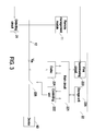
- FIG. 3 is a schematic circuit block diagram illustrating the remotely-controllable switching circuit of the device management system of FIG. 1 .
- the remotely-controllable switching circuit 22 comprises a main circuit 221, a controlling unit 222, a first handshaking circuit 223, a codec 224 (i.e. encoder/decoder), a storage unit 225, and a remotely-controllable switch element 226 (hereinafter called "switch element").
- the codec 224 is connected with the bus bar 12.
- the signal is decoded by the codec 224.
- the signal to be outputted from the remotely-controllable switching circuit 22 through the bus bar 12 is firstly encoded by the codec 224.
- the first handshaking circuit 223 is connected with a second handshaking circuit 213 of the detecting circuit 21 (see FIG. 4 ) and the main circuit 221. Consequently, a handshaking function of exchanging information between the first handshaking circuit 223 and the second handshaking circuit 213 can be achieved.
- the remotely-controllable switching circuit 22 and the detecting circuit 21 are in communication with each other through the first handshaking circuit 223 and the second handshaking circuit 213.
- the storage unit 225 is connected with the main circuit 221 for storing the information of the device 90.
- the identification number of the remotely-controllable switching circuit 22 is previously stored in the storage unit 225. According to the identification number, the remotely-controllable switching circuit 22 can be in communication with the remote management module 11 and the detecting circuit 21.
- the controlling unit 222 is connected with the switch element 226 for controlling the on/off states of the switch element 226.
- the main circuit 221 is connected with the controlling unit 222, the first handshaking circuit 223, the codec 224 and the storage unit 225.
- the main circuit 221 is used for controlling the overall operations of the remotely-controllable switching circuit 22. For example, the signal from the first handshaking circuit 223 or the signal from the codec 224 may be analyzed, processed, collected, calculated and/or integrated by the main circuit 221.
- the controlling unit 222 is driven by the main circuit 221 so as to control the on/off states of the switch element 226. Moreover, after the signal from the first handshaking circuit 223 or the signal from the codec 224 is analyzed, processed, collected, calculated and/or integrated by the main circuit 221, the analyzed or processed result is stored in the storage unit 225. Moreover, the data stored in the storage unit 225 may be read by the main circuit 221.
- the connection between the device 90 and the switch element 226 is detected by the detecting circuit 21. Consequently, through the second handshaking circuit 213 and the first handshaking circuit 223, the main circuit 221 of the remotely-controllable switching circuit 22 which is connected with the device 90 is enabled by the detecting circuit 21. Meanwhile, the controlling unit 222 is driven by the main circuit 221 to control the switch element 226 to be in the on state. In addition, the identification number stored in the storage unit 225 is transmitted from the main circuit 221 to the detecting circuit 21 through the second handshaking circuit 213 and the first handshaking circuit 223.
- the identification number of the remotely-controllable switching circuit 22 is registered to the detecting circuit 21.
- a location identification code of the remotely-controllable switching circuit 22 in the rack cabinet 9 is acquired.
- the detecting circuit 21 detects that the device 90 is removed from the rack cabinet 9
- the main circuit 221 of the remotely-controllable switching circuit 22 which is originally connected with the device 90 is disabled by the detecting circuit 21 through the second handshaking circuit 213 and the first handshaking circuit 223. Meanwhile, the controlling unit 222 is driven by the main circuit 221 to control the switch element 226 to be in the off state.
- the remote management module 11 issues a command to the codec 224 through the bus bar 12. After the command is decoded by the codec 224 and transmitted to the main circuit 221, the controlling unit 222 is driven by the main circuit 221 to control the switch element 226 to be in the off state. Under this circumstance, the device 90 which is suffered from breakdown or shutdown fails to receive the DC power Vdc.
- FIG. 4 is a schematic circuit block diagram illustrating the detecting circuit of the device management system of FIG. 1 .
- the detecting circuit 21 comprises a main circuit 211, a detecting unit 212, the second handshaking circuit 213, a codec 214, a storage unit 215, and a connection interface 216.
- the codec 214 is connected with the bus bar 12. When a signal from the bus bar 12 is received, the signal is decoded by the codec 214. In addition, the signal to be outputted from the detecting circuit 21 through the bus bar 12 is firstly encoded by the codec 214.
- the second handshaking circuit 213 is connected with the first handshaking circuit 223 of the remotely-controllable switching circuit 22 and the main circuit 211.
- the detecting circuit 21 and the remotely-controllable switching circuit 22 are in communication with each other through the first handshaking circuit 223 and the second handshaking circuit 213.
- the detecting unit 212 is connected with the main circuit 211 for detecting whether the device 90 is connected with the rack cabinet 9. According to the detecting result of the detecting unit 212, the main circuit 211 issues a command to the remotely-controllable switching circuit 22 which is connected with the device 90 through the first handshaking circuit 223 and the second handshaking circuit 213. According to the command, the path of the DC power Vdc to the device 90 is selectively conducted or interrupted.
- the remotely-controllable switching circuit 22 is enabled or disabled by the main circuit 211 through the second handshaking circuit 213.
- the received data may be stored in the storage unit 215 by the main circuit 211.
- the data stored in the storage unit 215 may be read by the main circuit 211.
- the registration message may be transmitted from the main circuit 211 to the device 90 through the bus bar 12.
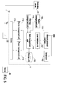
- FIG. 6 is a schematic circuit block diagram illustrating the remote management module of the device management system of FIG. 1 .
- the remote management module 11 comprises a main management unit 111, a device management unit 112, a power management unit 113, a storage unit 115, a warning management unit 116, and a user interface unit 117.
- the power management unit 113 is connected with the bus bar 12 for monitoring the statuses of the device 90 (i.e. the status of receiving the DC power Vdc) which is connected with the remotely-controllable switching circuit 22.
- the device management unit 112 is connected with the bus bar 12 for collecting the information of the device 90 which is connected with the remotely-controllable switching circuit 22 in real time.
- the information of the device 90 is received by the main management unit 111 through the device management unit 112. Moreover, according to a setting condition, the information of the device 90 is analyzed and processed by the main management unit 111.
- the setting condition includes a type of the device 90. That is, according to the type of the device 90, the information of the device 90 is analyzed and processed by the main management unit 111.
- the power status of the device 90 may be realized by the main management unit 111 through the power management unit 113. Since the real-time data of the device 90 can be stored and analyzed by the main management unit 111, the main management unit 111 can provide the information about the maintenance and the life of the device 90.
- the processed information of the device 90 and the power status of the device 90 may be stored into or read from the storage unit 115 by the main management unit 111.
- the user interface unit 117 is connected with the main management unit 111. Through the user interface unit 117, an external data may be inputted into the main management unit 111.
- the warning management unit 116 is connected with the main management unit 111. If the main management unit 111 confirms that a protection condition (e.g. an overvoltage protection condition, an overcurrent protection condition and/or an overloading protection condition) of the device 90 is satisfied according to the information of the device 90, the warning management unit 116 is driven to implement a waning process. In the warning process, the warning management unit 116 issues a waning sound, emits a warning light and/or transmits an electronic mail to notify the user that the device 90 needs to be protected.
- a protection condition e.g. an overvoltage protection condition, an overcurrent protection condition and/or an overloading protection condition
- the remote management module 11 may be controlled by an external device (not shown) or the user.
- the safety management unit 118 is connected with the main management unit 111.
- the safety management unit 118 is used for monitoring and filtering the identity of the user of the device 90, thereby increasing use safety of the device 90.
- the serial port 110 is connected with the user interface unit 117.
- An example of the serial port 110 includes but is not limited to a hyper-terminal.
- the remote management module 11 may be controlled by an external device (not shown) or the user.
- the information of the device 90 is analyzed and processed by the main management unit 111 according to the setting condition.
- the setting condition is stored in the storage unit 115.
- the setting condition stored in the storage unit 115 may be modified by the user through the network protocol interface 119 and/or the user interface unit 117.
- the present invention provides a device management module, a remote management module and a device management system.
- the device management system uses the device management module and the remote management module to individually and remotely control the devices within the rack cabinet. If any device within the rack cabinet is suffered from breakdown or shutdown, according to a command from the remote management module, a switch element of a remotely-controllable switching circuit is controlled to be in an off state. Since the switch element is turned off, the DC power is no longer received by the device which is suffered from breakdown or shutdown. Consequently, the purpose of resuming the device is achieved. In comparison with the conventional method of manually resuming the device, the use of the device management system of the present invention is time-saving and labor-saving and has enhanced utilization flexibility.
- the device management system of the present invention is capable of monitoring all devices of the rack cabinet. Moreover, the device management system of the present invention is capable of simultaneously monitoring all devices of the rack cabinet and storing and analyzing real-time data of the devices, thereby providing the information about the maintenance and the life of the device. Moreover, since the remote management module has additional function units (e.g. the safety management unit and the warning management unit), the device management system of the present invention has the function of protecting the devices of the rack cabinet.
- additional function units e.g. the safety management unit and the warning management unit
Landscapes
- Engineering & Computer Science (AREA)
- Computer Hardware Design (AREA)
- General Engineering & Computer Science (AREA)
- Microelectronics & Electronic Packaging (AREA)
- Business, Economics & Management (AREA)
- Emergency Management (AREA)
- Physics & Mathematics (AREA)
- General Physics & Mathematics (AREA)
- Power Sources (AREA)
- Selective Calling Equipment (AREA)
- Power Engineering (AREA)
Abstract
Description
- The present invention relates to a device management system, and more particularly to a device management system for remotely controlling devices of a rack cabinet of a data center and resuming any device which is suffered from breakdown or shutdown. The present invention also relates to a device management module and a remote management module of the device management system.
- With increasing development of computing technologies and networking technologies, the services and functions provided through networks are gradually increased. A data center is a facility used to house computers or servers. For providing intensive network applications, the number of computers or servers of the data center is gradually increased. Generally, a plurality of devices are accommodated within a rack cabinet of the data center in a hot-swappable manner. In addition, the data center may comprise a plurality of rack cabinets. For providing more services and functions, the number of devices within the data center is increased. Consequently, power supply, power distribution and power management become important issues. Conventionally, in the rack cabinet of the data center, a power distribution unit is used to distribute power among the devices.
- When AC power (e.g. utility power) is received by the rack cabinet, the AC power is transmitted from the power distribution unit to all devices within the rack cabinet. Each device has a power supply unit for receiving the AC power and converting the AC power into DC power, thereby powering circuitry of the device. Moreover, if one of the devices within the rack cabinet is suffered from breakdown or shutdown, the power distribution unit is responsible for stopping providing power to all devices within the rack cabinet. Consequently, the device which is suffered from breakdown or shutdown may be resumed.
- However, since the device has the power supply unit, the volume of the device is relatively bulky. Moreover, since the inner space of the rack cabinet is limited, the number of devices accommodated within the rack cabinet is restricted by the volume of the device. Moreover, since the power supply unit is disposed within the device, the heat-dissipating efficacy is usually unsatisfied. Moreover, if any device within the rack cabinet is suffered from breakdown or shutdown, it is necessary to stop the power distribution unit from providing electric power to all devices of the rack cabinet. In other words, the electric power to the device which is suffered from breakdown or shutdown cannot be stopped individually. Under this circumstance, the utilization flexible of the rack cabinet is impaired. Moreover, for manually removing the device which is suffered from breakdown or shutdown and resuming the device, the worker has to move the data center to successively check all devices of the rack cabinet. After the device which is suffered from breakdown or shutdown is searched, the user may start repairing or resuming the device. In other words, the way of maintaining or resuming the device of the rack cabinet is time-consuming and labor-intensive.
- For reducing the volume of the device and enhancing the heat-dissipating efficacy of the device, a power shelf is installed in the rack cabinet and the power distribution unit is omitted. The power shelf is used for converting AC power into DC power and transmitting the DC power to all devices of the rack cabinet. Under this circumstance, it is not necessary to install the power supply unit in each device. Consequently, the volume of the device is reduced, and the heat-dissipating efficacy of the device is enhanced. Since the power shelf does not have the function of controlling power to one or more devices, if the device within the rack cabinet is suffered from breakdown or shutdown, the user may manually remove the device which is suffered from breakdown or shutdown and resume the device. Similarly, the way of maintaining or resuming the device of the rack cabinet is time-consuming and labor-intensive.
- Therefore, there is a need of providing a device management module, a remote management module and a device management system in order to eliminate the above drawbacks.
- The present invention provides a device management module, a remote management module and a device management system. The device management system uses the device management module and the remote management module to individually and remotely control the devices within the rack cabinet. If any device within the rack cabinet is suffered from breakdown or shutdown, according to a command from the remote management module, a switch element of a remotely-controllable switching circuit is controlled to be in an off state. Since the switch element is turned off, the DC power is no longer received by the device which is suffered from breakdown or shutdown. Consequently, the purpose of resuming the device is achieved. In comparison with the conventional method of manually resuming the device, the use of the device management system of the present invention is time-saving and labor-saving.
- The present invention provides a device management system for monitoring all devices of the rack cabinet and storing and analyzing real-time data of the devices, thereby providing the information about the maintenance and the life of the device.
- In accordance with an aspect of the present invention, there is provided a device management system for managing at least one hot-swappable device within a rack cabinet. The device management system includes a bus bar, a device management module, and a remote management module. The bus bar is used for transferring signals and DC power. The device management module is used for monitoring whether the device is installed in the rack cabinet and collecting information of the device which is installed in the rack cabinet. The device management module includes at least one remotely-controllable switching circuit and a detecting circuit. The remotely-controllable switching circuit is installed in an installation block. A first end of the remotely-controllable switching circuit is connected with the bus bar. A second end of the remotely-controllable switching circuit is connected with the device which is installed in the rack cabinet. During operation of the remotely-controllable switching circuit, the information of the device is collected by the remotely-controllable switching circuit in real time. The detecting circuit is connected with the bus bar and in communication with the remotely-controllable switching circuit for detecting whether the device is installed in the rack cabinet. A location table about a location of the remotely-controllable switching circuit in the installation block is previously stored in the detecting circuit. When the device is installed in the rack cabinet, the remotely-controllable switching circuit connected with the device is enabled by the detecting circuit according to the location table. The remote management module is in communication with the remotely-controllable switching circuit and the detecting circuit through the bus bar. The information of the device is acquired by the remote management module through the remotely-controllable switching circuit. A switch element of the remotely-controllable switching circuit which is connected to the device is selectively turned on or turned off by the remote management module. When the switch element is turned on, the DC power is transmitted to the device through the switch element.
- In accordance with another aspect of the present invention, there is provided a device management module of a device management system for monitoring at least one hot-swappable device within a rack cabinet and collecting information of the device. The device management module includes at least one remotely-controllable switching circuit and a detecting circuit. The remotely-controllable switching circuit is installed in an installation block. A first end of the remotely-controllable switching circuit is connected with a bus bar. A second end of the remotely-controllable switching circuit is connected with the device which is installed in the rack cabinet. During operation of the remotely-controllable switching circuit, the information of the device is collected by the remotely-controllable switching circuit in real time. The detecting circuit is connected with the bus bar and in communication with the remotely-controllable switching circuit for detecting whether the device is installed in the rack cabinet. A location table about a location of the remotely-controllable switching circuit in the installation block is previously stored in the detecting circuit. When the device is installed in the rack cabinet, the remotely-controllable switching circuit connected with the device is enabled by the detecting circuit according to the location table.
- In accordance with a further aspect of the present invention, there is provided a remote management module of a device management system. The remote management module is in communication with a remotely-controllable switching circuit and a detecting circuit of the device management system. The remote management module includes a power management unit, a device management unit, a main management unit, a storage unit, a user interface unit, and a warning management unit. The power management unit is connected with the bus bar for monitoring a DC power which is received by a device connected with the remotely-controllable switching circuit. The device management unit is connected with the bus bar for collecting information of the device connected with the remotely-controllable switching circuit in real time. The main management unit is used for receiving the information of the device through the device management unit. The information of the device is analyzed and processed by the main management unit according to a setting condition. A power status of the device is realized by the main management unit through the power management unit. After the information of the device is analyzed and processed by the main management unit, processed information of the device is obtained. The processed information and the power status are stored in or read from the storage unit in real time. The user interface unit is connected with the main management unit. An external data is inputted into the main management unit through the user interface unit. The warning management unit is connected with the main management unit. If the main management unit confirms that a protection condition of the device is satisfied, the warning management unit is driven to implement a waning process.
- The above contents of the present invention will become more readily apparent to those ordinarily skilled in the art after reviewing the following detailed description and accompanying drawings, in which:
-
-
FIG. 1 schematically illustrates the architecture of a device management system according to an embodiment of the present invention; -
FIG. 2 schematically illustrates a rack cabinet used in the device management system ofFIG. 1 ; -
FIG. 3 is a schematic circuit block diagram illustrating the remotely-controllable switching circuit of the device management system ofFIG. 1 ; -
FIG. 4 is a schematic circuit block diagram illustrating the detecting circuit of the device management system ofFIG. 1 ; -
FIG. 5 schematically illustrates an installation block for installing the remotely-controllable switching circuit of the device management system ofFIG. 1 ; and -
FIG. 6 is a schematic circuit block diagram illustrating the remote management module of the device management system ofFIG. 1 . - The present invention will now be described more specifically with reference to the following embodiments. It is to be noted that the following descriptions of preferred embodiments of this invention are presented herein for purpose of illustration and description only. It is not intended to be exhaustive or to be limited to the precise form disclosed.
-
FIG. 1 schematically illustrates the architecture of a device management system according to an embodiment of the present invention.FIG. 2 schematically illustrates a rack cabinet used in the device management system ofFIG. 1 . As shown inFIG. 1 , the device management system (DMS) 1 is used for automatically and efficiently managing at least onedevice 90 within a rack cabinet 9 (seeFIG. 2 ). Therack cabinet 9 is installed in a data center. An example of thedevice 90 includes but is not limited to a computer or a server. Thedevice 90 may be installed in therack cabinet 9 in a hot swappable manner. Moreover, apower shelf 91 is disposed within therack cabinet 9 for receiving AC power Vac (i.e. utility power) and converting the AC power Vac into DC power Vdc, thereby powering alldevices 90 of therack cabinet 9. - The
device management system 1 comprises aremote management module 11, abus bar 12, and a device management module (DMM) 2. Thebus bar 12 has the functions of transferring signals and electric power. For example, thebus bar 12 comprises a power cable (not shown) for transferring electric power and a signal cable (not shown) for transferring signals. Moreover, the signal cable can transfer signals complying with a power line communication protocol. Thebus bar 12 is connected with thepower shelf 91 for receiving the DC power Vdc from thepower shelf 91. That is, thebus bar 12 not only provides a path of transferring electric power but also provides a path of transferring monitor signals of thedevice management system 1. - The device management module 2 is connected with the
bus bar 12. When thedevice 90 is installed in therack cabinet 9, the device management module 2 is connected with thedevice 90. The device management module 2 is used for initializing and designating an actual position of thedevice 90 in therack cabinet 9, monitoring whether thedevice 90 is installed in therack cabinet 9 and collecting the information of thedevice 90 in therack cabinet 9. The device management module 2 further comprises a detectingcircuit 21 and at least one remotely-controllable switching circuit 22. The device management module 2 comprises one remotely-controllable switching circuit 22 or a plurality of remotely-controllable switching circuits 22. The number of the at least one remotely-controllable switching circuit 22 is equal to the number of the at least onedevice 90. The remotely-controllable switching circuit 22 is disposed within therack cabinet 9, and installed in an installation block 92 (seeFIG. 5 ). Theinstallation block 92 is arranged between thebus bar 12 and thedevice 90. An example of theinstallation block 92 includes but is not limited to an installation plate. Moreover, before therack cabinet 9 leaves the factory, theinstallation block 92 is installed in therack cabinet 9. A first end of the remotely-controllable switching circuit 22 is connected with thebus bar 12. A second end of the remotely-controllable switching circuit 22 is connected with acorresponding device 90 which is installed in therack cabinet 9. During operations, the information of thedevice 90 may be collected by the remotely-controllable switching circuit 22 in real time. Moreover, each remotely-controllable switching circuit 22 has a unique identification number. When thedevice management system 1 is operated, the remotely-controllable switching circuit 22 is registered to the detectingcircuit 21 according to the identification number. After the remotely-controllable switching circuit 22 is registered, a location identification code of the remotely-controllable switching circuit 22 in therack cabinet 9 is acquired. The detectingcircuit 21 is in communication with the remotely-controllable switching circuit 22 through thebus bar 12. Consequently, a location table about the remotely-controllable switching circuit 22 of theinstallation block 92 is established by the detectingcircuit 21. When the remotely-controllable switching circuit 22 is connected with thedevice 90, the remotely-controllable switching circuit 22 connected with thedevice 90 is enabled by the detectingcircuit 21 according to the location table, and associated data is transmitted from the detectingcircuit 21 to thedevice 90. Accordingly, thedevice 90 can be registered to theremote management module 11. - The
remote management module 11 is connected with thebus bar 12. In addition, theremote management module 11 is in communication with the remotely-controllable switching circuit 22 and the detectingcircuit 21 through thebus bar 12. The information of thedevice 90 may be acquired by theremote management module 11 through the remotely-controllable switching circuit 22. In addition, theremote management module 11 may monitor all statuses of thedevice 90. The statuses of thedevice 90 includes the type of thedevice 90, the voltage of thedevice 90, the current of thedevice 90, the operating status of thedevice 90 and the location message of thedevice 90. Moreover, according to a command from theremote management module 11, a switch element 226 (as shown inFIG. 3 ) of the remotely-controllable switching circuit 22 is selectively turned on or turned off, so that the path of the DC power Vdc to thedevice 90 is selectively conducted or interrupted. Theswitch element 226 is located in the path of the DC power Vdc to thedevice 90. For example, theswitch element 226 is arranged between thepower shelf 91 and thedevice 90, and connected with an input terminal of thedevice 90. When theswitch element 226 is turned on according to the command from theremote management module 11, the DC power Vdc is transmitted to thedevice 90 through theswitch element 226 in order to power thedevice 90. - The operations of the device management system of
FIG. 1 will be illustrated in more details as follows. After thedevice 90 is installed in therack cabinet 9 and connected with the remotely-controllable switching circuit 22 of theinstallation block 92, the detectingcircuit 21 detects that thedevice 90 is connected with the remotely-controllable switching circuit 22. Consequently, the remotely-controllable switching circuit 22 is enabled by the detectingcircuit 21. After the remotely-controllable switching circuit 22 is enabled, theswitch element 226 of the remotely-controllable switching circuit 22 is turned on, and the DC power Vdc is transmitted to thedevice 90 to power thedevice 90. During operations of the remotely-controllable switching circuit 22, the information of thedevice 90 is collected by the remotely-controllable switching circuit 22 in real time. In addition, the identification number of the remotely-controllable switching circuit 22 is transmitted to the detectingcircuit 21. According to the identification number, the remotely-controllable switching circuit 22 is registered to the detectingcircuit 21. During the registering process, the identification number is compared with the location table by the detectingcircuit 21. Consequently, an address of the remotely-controllable switching circuit 22 which is connected with thedevice 90 is realized by the detectingcircuit 21. In other words, the remotely-controllable switching circuit 22 is located by the detectingcircuit 21. Then, a registration message is transmitted from the detectingcircuit 21 to thedevice 90 through thebus bar 12. The registration message contains a serial number of therack cabinet 9, the identification number and a location identification code of the remotely-controllable switching circuit 22. According to the registration message, thedevice 90 can be registered to theremote management module 11. Since different remotely-controllable switching circuits 22 have different identification numbers, the location identification codes contained in the registration messages are independent and different. After the location identification code of the remotely-controllable switching circuit 22 which is connected with thedevice 90 is realized by theremote management module 11, theswitch element 226 of the remotely-controllable switching circuit 22 is selectively turned on or turned off according to the location identification code. Consequently, if anydevice 90 within therack cabinet 9 is suffered from breakdown or shutdown, theswitch element 226 of the remotely-controllable switching circuit 22 is controlled to be in the off state according to the location identification code of the remotely-controllable switching circuit 22. Under this circumstance, thedevice 90 which is suffered from breakdown or shutdown fails to receive the DC power Vdc, and thus thedevice 90 can be resumed. Of course, for disabling a normally-operateddevice 90, the location identification code of the remotely-controllable switching circuit 22 which is connected with thedevice 90 may be realized by theremote management module 11. According to the location identification code of the remotely-controllable switching circuit 22, theswitch element 226 of the remotely-controllable switching circuit 22 which is connected with the normally-operateddevice 90 is controlled to be in the off state. Under this circumstance, the normally-operateddevice 90 fails to receive the DC power Vdc, and thus thedevice 90 can be resumed. Moreover, if thedevice 90 is removed from therack cabinet 9 and disconnected from the corresponding remotely-controllable switching circuit 22, the remotely-controllable switching circuit 22 is disabled by the detectingcircuit 21. Consequently, theswitch element 226 is controlled to be in the off state. -
FIG. 3 is a schematic circuit block diagram illustrating the remotely-controllable switching circuit of the device management system ofFIG. 1 . As shown inFIG. 3 , the remotely-controllable switching circuit 22 comprises amain circuit 221, a controllingunit 222, afirst handshaking circuit 223, a codec 224 (i.e. encoder/decoder), astorage unit 225, and a remotely-controllable switch element 226 (hereinafter called "switch element"). Thecodec 224 is connected with thebus bar 12. When a signal is transmitted from the detectingcircuit 21 or theremote management module 11 to the remotely-controllable switching circuit 22 through thebus bar 12, the signal is decoded by thecodec 224. In addition, the signal to be outputted from the remotely-controllable switching circuit 22 through thebus bar 12 is firstly encoded by thecodec 224. Thefirst handshaking circuit 223 is connected with asecond handshaking circuit 213 of the detecting circuit 21 (seeFIG. 4 ) and themain circuit 221. Consequently, a handshaking function of exchanging information between thefirst handshaking circuit 223 and thesecond handshaking circuit 213 can be achieved. In other words, the remotely-controllable switching circuit 22 and the detectingcircuit 21 are in communication with each other through thefirst handshaking circuit 223 and thesecond handshaking circuit 213. Thestorage unit 225 is connected with themain circuit 221 for storing the information of thedevice 90. In addition, the identification number of the remotely-controllable switching circuit 22 is previously stored in thestorage unit 225. According to the identification number, the remotely-controllable switching circuit 22 can be in communication with theremote management module 11 and the detectingcircuit 21. The controllingunit 222 is connected with theswitch element 226 for controlling the on/off states of theswitch element 226. Themain circuit 221 is connected with the controllingunit 222, thefirst handshaking circuit 223, thecodec 224 and thestorage unit 225. Themain circuit 221 is used for controlling the overall operations of the remotely-controllable switching circuit 22. For example, the signal from thefirst handshaking circuit 223 or the signal from thecodec 224 may be analyzed, processed, collected, calculated and/or integrated by themain circuit 221. According to the signal from thefirst handshaking circuit 223 or the signal from thecodec 224, the controllingunit 222 is driven by themain circuit 221 so as to control the on/off states of theswitch element 226. Moreover, after the signal from thefirst handshaking circuit 223 or the signal from thecodec 224 is analyzed, processed, collected, calculated and/or integrated by themain circuit 221, the analyzed or processed result is stored in thestorage unit 225. Moreover, the data stored in thestorage unit 225 may be read by themain circuit 221. - After the
device 90 is installed in therack cabinet 9 and connected with theswitch element 226 of the corresponding remotely-controllable switching circuit 22, the connection between thedevice 90 and theswitch element 226 is detected by the detectingcircuit 21. Consequently, through thesecond handshaking circuit 213 and thefirst handshaking circuit 223, themain circuit 221 of the remotely-controllable switching circuit 22 which is connected with thedevice 90 is enabled by the detectingcircuit 21. Meanwhile, the controllingunit 222 is driven by themain circuit 221 to control theswitch element 226 to be in the on state. In addition, the identification number stored in thestorage unit 225 is transmitted from themain circuit 221 to the detectingcircuit 21 through thesecond handshaking circuit 213 and thefirst handshaking circuit 223. Consequently, the identification number of the remotely-controllable switching circuit 22 is registered to the detectingcircuit 21. After the remotely-controllable switching circuit 22 is registered, a location identification code of the remotely-controllable switching circuit 22 in therack cabinet 9 is acquired. On the other hand, when the detectingcircuit 21 detects that thedevice 90 is removed from therack cabinet 9, themain circuit 221 of the remotely-controllable switching circuit 22 which is originally connected with thedevice 90 is disabled by the detectingcircuit 21 through thesecond handshaking circuit 213 and thefirst handshaking circuit 223. Meanwhile, the controllingunit 222 is driven by themain circuit 221 to control theswitch element 226 to be in the off state. Moreover, if thedevice 90 within therack cabinet 9 is suffered from breakdown or shutdown, theremote management module 11 issues a command to thecodec 224 through thebus bar 12. After the command is decoded by thecodec 224 and transmitted to themain circuit 221, the controllingunit 222 is driven by themain circuit 221 to control theswitch element 226 to be in the off state. Under this circumstance, thedevice 90 which is suffered from breakdown or shutdown fails to receive the DC power Vdc. -
FIG. 4 is a schematic circuit block diagram illustrating the detecting circuit of the device management system ofFIG. 1 . As shown inFIG. 4 , the detectingcircuit 21 comprises amain circuit 211, a detectingunit 212, thesecond handshaking circuit 213, acodec 214, astorage unit 215, and aconnection interface 216. Thecodec 214 is connected with thebus bar 12. When a signal from thebus bar 12 is received, the signal is decoded by thecodec 214. In addition, the signal to be outputted from the detectingcircuit 21 through thebus bar 12 is firstly encoded by thecodec 214. Thesecond handshaking circuit 213 is connected with thefirst handshaking circuit 223 of the remotely-controllable switching circuit 22 and themain circuit 211. Consequently, a handshaking function of exchanging information between thefirst handshaking circuit 223 and thesecond handshaking circuit 213 can be achieved. In other words, the detectingcircuit 21 and the remotely-controllable switching circuit 22 are in communication with each other through thefirst handshaking circuit 223 and thesecond handshaking circuit 213. The detectingunit 212 is connected with themain circuit 211 for detecting whether thedevice 90 is connected with therack cabinet 9. According to the detecting result of the detectingunit 212, themain circuit 211 issues a command to the remotely-controllable switching circuit 22 which is connected with thedevice 90 through thefirst handshaking circuit 223 and thesecond handshaking circuit 213. According to the command, the path of the DC power Vdc to thedevice 90 is selectively conducted or interrupted. An example of theconnection interface 216 includes but is not limited to a RS-232 interface or an Ethernet interface for receiving an external data. Consequently, the location table of the detectingcircuit 21 may be updated through theconnection interface 216. Thestorage unit 215 is used for storing the location table or associated data. Themain circuit 211 is connected with the detectingunit 212, thesecond handshaking circuit 213, thecodec 214, thestorage unit 215 and theconnection interface 216. Themain circuit 211 is used for controlling the overall operations of the detectingcircuit 21. For example, the signal from thesecond handshaking circuit 213 or the signal from thecodec 214 may be analyzed, processed, collected, calculated and/or integrated by themain circuit 211. According to the detecting result of the detectingunit 212, the remotely-controllable switching circuit 22 is enabled or disabled by themain circuit 211 through thesecond handshaking circuit 213. Moreover, the received data may be stored in thestorage unit 215 by themain circuit 211. Moreover, the data stored in thestorage unit 215 may be read by themain circuit 211. Moreover, the registration message may be transmitted from themain circuit 211 to thedevice 90 through thebus bar 12. -
FIG. 6 is a schematic circuit block diagram illustrating the remote management module of the device management system ofFIG. 1 . As shown inFIG. 6 , theremote management module 11 comprises amain management unit 111, adevice management unit 112, apower management unit 113, astorage unit 115, awarning management unit 116, and auser interface unit 117. Thepower management unit 113 is connected with thebus bar 12 for monitoring the statuses of the device 90 (i.e. the status of receiving the DC power Vdc) which is connected with the remotely-controllable switching circuit 22. Thedevice management unit 112 is connected with thebus bar 12 for collecting the information of thedevice 90 which is connected with the remotely-controllable switching circuit 22 in real time. The information of thedevice 90 is received by themain management unit 111 through thedevice management unit 112. Moreover, according to a setting condition, the information of thedevice 90 is analyzed and processed by themain management unit 111. For example, the setting condition includes a type of thedevice 90. That is, according to the type of thedevice 90, the information of thedevice 90 is analyzed and processed by themain management unit 111. Moreover, the power status of thedevice 90 may be realized by themain management unit 111 through thepower management unit 113. Since the real-time data of thedevice 90 can be stored and analyzed by themain management unit 111, themain management unit 111 can provide the information about the maintenance and the life of thedevice 90. Moreover, the processed information of thedevice 90 and the power status of thedevice 90 may be stored into or read from thestorage unit 115 by themain management unit 111. Theuser interface unit 117 is connected with themain management unit 111. Through theuser interface unit 117, an external data may be inputted into themain management unit 111. Thewarning management unit 116 is connected with themain management unit 111. If themain management unit 111 confirms that a protection condition (e.g. an overvoltage protection condition, an overcurrent protection condition and/or an overloading protection condition) of thedevice 90 is satisfied according to the information of thedevice 90, thewarning management unit 116 is driven to implement a waning process. In the warning process, thewarning management unit 116 issues a waning sound, emits a warning light and/or transmits an electronic mail to notify the user that thedevice 90 needs to be protected. - In some embodiments, the
remote management module 11 further comprises acodec 114, asafety management unit 118, anetwork protocol interface 119, and aserial port 110. Thecodec 114 is connected with thebus bar 12. When a signal from thebus bar 12 is received, the signal is decoded by thecodec 114. In addition, the signal to be outputted from theremote management module 11 through thebus bar 12 is firstly encoded by thecodec 114. Thenetwork protocol interface 119 is connected with theuser interface unit 117. An example of thenetwork protocol interface 119 includes but is not limited to a web protocol interface, a Telnet protocol interface or a simple network management protocol (SNMP) interface. Through thenetwork protocol interface 119, theremote management module 11 may be controlled by an external device (not shown) or the user. Thesafety management unit 118 is connected with themain management unit 111. Thesafety management unit 118 is used for monitoring and filtering the identity of the user of thedevice 90, thereby increasing use safety of thedevice 90. Theserial port 110 is connected with theuser interface unit 117. An example of theserial port 110 includes but is not limited to a hyper-terminal. Through theserial port 110, theremote management module 11 may be controlled by an external device (not shown) or the user. - As mentioned above, the information of the
device 90 is analyzed and processed by themain management unit 111 according to the setting condition. Moreover, the setting condition is stored in thestorage unit 115. Moreover, for complying with the stored data and the operation modes ofdifferent devices 90, the setting condition stored in thestorage unit 115 may be modified by the user through thenetwork protocol interface 119 and/or theuser interface unit 117. - From the above descriptions, the present invention provides a device management module, a remote management module and a device management system. The device management system uses the device management module and the remote management module to individually and remotely control the devices within the rack cabinet. If any device within the rack cabinet is suffered from breakdown or shutdown, according to a command from the remote management module, a switch element of a remotely-controllable switching circuit is controlled to be in an off state. Since the switch element is turned off, the DC power is no longer received by the device which is suffered from breakdown or shutdown. Consequently, the purpose of resuming the device is achieved. In comparison with the conventional method of manually resuming the device, the use of the device management system of the present invention is time-saving and labor-saving and has enhanced utilization flexibility. Moreover, the device management system of the present invention is capable of monitoring all devices of the rack cabinet. Moreover, the device management system of the present invention is capable of simultaneously monitoring all devices of the rack cabinet and storing and analyzing real-time data of the devices, thereby providing the information about the maintenance and the life of the device. Moreover, since the remote management module has additional function units (e.g. the safety management unit and the warning management unit), the device management system of the present invention has the function of protecting the devices of the rack cabinet.
Claims (15)
- A device management system (1) for managing at least one device (90) hot-swappable within a rack cabinet (9), the device management system (1) comprising:a bus bar (12) for transferring signals and DC power (Vdc);a device management module (2) for monitoring whether the device (90) is installed in the rack cabinet (9) and collecting information of the device (90) which is installed in the rack cabinet (9), wherein the device management module (2) comprises:at least one remotely-controllable switching circuit (22) installed in an installation block (92), wherein a first end of the remotely-controllable switching circuit (22) is connected with the bus bar (12), and a second end of the remotely-controllable switching circuit (22) is connected with the device (90) which is installed in the rack cabinet (9), wherein during operation of the remotely-controllable switching circuit (22), the information of the device (90) is collected by the remotely-controllable switching circuit (22) in real time; anda detecting circuit (21) connected with the bus bar (12) and in communication with the remotely-controllable switching circuit (22) for detecting whether the device (90) is installed in the rack cabinet (9), wherein a location table about a location of the remotely-controllable switching circuit (22) in the installation block (92) is previously stored in the detecting circuit (21), wherein when the device (90) is installed in the rack cabinet (9), the remotely-controllable switching circuit (22) connected with the device (90) is enabled by the detecting circuit (21) according to the location table; anda remote management module (11) in communication with the remotely-controllable switching circuit (22) and the detecting circuit (21) through the bus bar (12), wherein the information of the device (90) is acquired by the remote management module (11) through the remotely-controllable switching circuit (22), wherein a switch element (226) of the remotely-controllable switching circuit (22) which is connected to the device (90) is selectively turned on or turned off by the remote management module (11), wherein when the switch element (226) is turned on, the DC power (Vdc) is transmitted to the device (90) through the switch element (226).
- The device management system according to claim 1, wherein the installation block (92) is disposed within the rack cabinet (9), and wherein the number of the at least one remotely-controllable switching circuit (22) is equal to the number of the at least one device (90).
- The device management system according to claim 1 or 2, wherein when the device (90) is installed in the rack cabinet (9) and connected with the remotely-controllable switching circuit (22), the remotely-controllable switching circuit (22) is enabled by the detecting circuit (221), wherein when the device (90) is removed from the rack cabinet (9) and disconnected from the remotely-controllable switching circuit (2), the remotely-controllable switching circuit (22) is disabled by the detecting circuit (21).
- The device management system according to any of the claims 1 to 3, wherein the switch element (226) is located in a path of transmitting the DC power (Vdc) to the device (90), and the switch element (226) is connected with an input terminal of the device (90).
- The device management system according to any of the claims 1 to 4, wherein the remotely-controllable switching circuit (22) has a unique identification number.
- The device management system according to claim 5, wherein while the remotely-controllable switching circuit (22) is enabled by the detecting circuit (21), the identification number is transmitted from the remotely-controllable switching circuit (22) to the detecting circuit (21), wherein by comparing the identification number with the location table, an address of the remotely-controllable switching circuit (22) connected with the device (90) is realized by the detecting circuit (21).
- The device management system according to claim 6, wherein after the address of the remotely-controllable switching circuit (22) connected with the device (90) is realized by the detecting circuit (21), the detecting circuit (21) issues a registration message to the device (90), wherein according to the registration message, the device (90) is registered to the remote management module (11), wherein according to the registration message, the switch element (226) of the remotely-controllable switching circuit (22) is controlled to be turned on or turned off by the remote management module (11), wherein the registration message contains a serial number of the rack cabinet (9), the identification number and a location identification code of the remotely-controllable switching circuit (22).
- The device management system according to any of the claims 5 to 7, wherein the remotely-controllable switching circuit (22) further comprises:a storage unit (225) for storing the information of the device (90) and storing the identification number;a codec (224), wherein a signal received by the remotely-controllable switching circuit (22) through the bus bar (12) is decoded by the codec (224), wherein a signal to be outputted from the remotely-controllable switching circuit (22) through the bus bar (12) is firstly encoded by the codec (224);a first handshaking circuit (223), wherein the first handshaking circuit (223) and a second handshaking circuit (213) of the detecting circuit (21) are connected with each other, so that the remotely-controllable switching circuit (22) and the detecting circuit (21) are in communication with each other;a controlling unit (222) connected with the switch element (226) for controlling the switch element (226) to be turned on or turned off; anda main circuit (221) for controlling overall operations of the remotely-controllable switching circuit (22).
- The device management system according to any of the claims 1 to 8, wherein the detecting circuit (21) further comprises:a codec (214), wherein a signal received by the remotely-controllable switching circuit (22) through the bus bar (12) is decoded by the codec (214), wherein a signal to be outputted from the remotely-controllable switching circuit (22) through the bus bar (12) is firstly encoded by the codec (214);a detecting unit (212) for detecting whether the device (90) is connected with the rack cabinet (9); anda main circuit (211) for controlling overall operations of the detecting circuit (21).
- The device management system according to claim 9, wherein the detecting circuit (21) further comprises a connection interface (216) for receiving an external data, wherein the connection interface (216) is a RS-232 interface or an Ethernet interface.
- The device management system according to any of the claims 1 to 10, wherein the remote management module (11) further comprises:a power management unit (113) connected with the bus bar (12) for monitoring the DC power (Vdc) which is received by the device (90);a device management unit (112) connected with the bus bar (12) for collecting the information of the device (90) which is connected with the remotely-controllable switching circuit (22) in real time;a main management unit (111), wherein the information of the device (90) is received by the main management unit (111) through the device management unit (112), wherein the information of the device (90) is analyzed and processed by the main management unit (111) according to a setting condition, wherein a power status of the device (90) is realized by the main management unit (111) through the power management unit (113);a storage unit (115), wherein after the information of the device (90) is analyzed and processed by the main management unit (111), a processed information of the device (90) is obtained, wherein the processed information and the power status are stored in or read from the storage unit (115) in real time;a user interface unit (117) connected with the main management unit (111), wherein an external data is inputted into the main management unit (111) through the user interface unit (117); anda warning management unit (116) connected with the main management unit (111), wherein if the main management unit (111) confirms that a protection condition of the device (90) is satisfied, the warning management unit (116) is driven to implement a waning process.
- The device management system according to claim 11, wherein the setting condition includes a type of the device (90), and according to the type of the device (90), the information of the device (90) is analyzed and processed by the main management unit (111), wherein the protection condition comprises an overvoltage protection condition, an overcurrent protection condition and/or an overloading condition, wherein when the warning process is implemented, the warning management unit (116) issues a waning sound, emits a warning light and/or transmits an electronic mail.
- The device management system according to claim 11 or 12, wherein the remote management module (11) further comprises:a codec (114), and the codec (114) is connected with the bus bar (12), wherein a signal received by the remote management module (11) through the bus bar (12) is decoded by the codec (114), wherein a signal to be outputted from the remote management module (11) through the bus bar (12) is firstly encoded by the codec (114);a network protocol interface (119), wherein the network protocol interface (119) comprises a web protocol interface, a Telnet protocol interface and/or a simple network management protocol (SNMP) interface; anda safety management unit (118), wherein the safety management unit (118) is connected with the main management unit (111) for monitoring and filtering an identity of a user of the device (90).
- A device management module (2) of a device management system (1) for monitoring at least one device (90) hot-swappable within a rack cabinet (9) and collecting information of the at least one device (90), the device management module (2) comprising:at least one remotely-controllable switching circuit (22) installed in an installation block (92), wherein a first end of the remotely-controllable switching circuit (22) is connected with a bus bar (12), and a second end of the remotely-controllable switching circuit (22) is connected with the device (90) which is installed in the rack cabinet (9), wherein during operation of the remotely-controllable switching circuit (22), the information of the device (90) is collected by the remotely-controllable switching circuit (22) in real time; anda detecting circuit (21) connected with the bus bar (12) and in communication with the remotely-controllable switching circuit (22) for detecting whether the device (90) is installed in the rack cabinet (9), wherein a location table about a location of the remotely-controllable switching circuit (22) in the installation block (92) is previously stored in the detecting circuit (21), wherein when the device (90) is installed in the rack cabinet (9), the remotely-controllable switching circuit (22) connected with the device (90) is enabled by the detecting circuit (21) according to the location table.
- A remote management module (11) of a device management system (1), the remote management module (11) being in communication with a remotely-controllable switching circuit (22) and a detecting circuit (21) of the device management system (1) through a bus bar (12), the remote management module (11) comprising:a power management unit (113) connected with the bus bar (12) for monitoring a DC power (Vdc) which is received by a device (90) connected with the remotely-controllable switching circuit (22);a device management unit (112) connected with the bus bar (12) for collecting information of the device (90) connected with the remotely-controllable switching circuit (22) in real time;a main management unit (111) for receiving the information of the device (90) through the device management unit (112), wherein the information of the device (90) is analyzed and processed by the main management unit (111) according to a setting condition, wherein a power status of the device (90) is realized by the main management unit (111) through the power management unit (113);a storage unit (115), wherein after the information of the device (90) is analyzed and processed by the main management unit (111), a processed information of the device (90) is obtained, wherein the processed information and the power status are stored in or read from the storage unit (115) in real time;a user interface unit (117) connected with the main management unit (111), wherein an external data is inputted into the main management unit (111) through the user interface unit (117); anda warning management unit (116) connected with the main management unit (111), wherein if the main management unit (111) confirms that a protection condition of the device (90) is satisfied, the warning management unit (116) is driven to implement a waning process.
Applications Claiming Priority (1)
| Application Number | Priority Date | Filing Date | Title |
|---|---|---|---|
| TW102137772A TWI510934B (en) | 2013-10-18 | 2013-10-18 | Device management module, remotely management module and device management system employing same |
Publications (3)
| Publication Number | Publication Date |
|---|---|
| EP2863723A2 true EP2863723A2 (en) | 2015-04-22 |
| EP2863723A3 EP2863723A3 (en) | 2015-08-12 |
| EP2863723B1 EP2863723B1 (en) | 2017-03-08 |
Family
ID=50972425
Family Applications (1)
| Application Number | Title | Priority Date | Filing Date |
|---|---|---|---|
| EP14161693.8A Active EP2863723B1 (en) | 2013-10-18 | 2014-03-26 | Device management module, remote management module and device management system employing same |
Country Status (3)
| Country | Link |
|---|---|
| US (1) | US9019114B1 (en) |
| EP (1) | EP2863723B1 (en) |
| TW (1) | TWI510934B (en) |
Cited By (5)
| Publication number | Priority date | Publication date | Assignee | Title |
|---|---|---|---|---|
| CN105656210A (en) * | 2015-08-05 | 2016-06-08 | 南京大全电气有限公司 | Intelligent monitoring operation and maintenance system for switch cabinets |
| US11157057B1 (en) | 2020-05-28 | 2021-10-26 | Ovh | Systems and methods for electric systems monitoring and/or failure detection |
| EP3916954A1 (en) * | 2020-05-28 | 2021-12-01 | Ovh | Systems and methods for electric systems monitoring and/or failure detection |
| US11281267B2 (en) | 2018-06-08 | 2022-03-22 | Ovh | Methods and systems for identifying a connection path between a power source and a load |
| US11489553B1 (en) | 2021-04-13 | 2022-11-01 | Ovh | System and method for identifying a connection between a power distribution unit and an electric device |
Families Citing this family (10)
| Publication number | Priority date | Publication date | Assignee | Title |
|---|---|---|---|---|
| TWI611290B (en) * | 2015-09-04 | 2018-01-11 | 神雲科技股份有限公司 | Method for monitoring server racks |
| US10164843B2 (en) | 2015-09-21 | 2018-12-25 | Ruby Tech Corporation | Network switch, device management system, and device management method thereof |
| TWI586123B (en) * | 2015-09-21 | 2017-06-01 | 德勝科技股份有限公司 | Network switch, device management system, and device management method thereof |
| TWI571195B (en) * | 2015-10-06 | 2017-02-11 | 神雲科技股份有限公司 | Server cabinet |
| US10298479B2 (en) | 2016-05-09 | 2019-05-21 | Mitac Computing Technology Corporation | Method of monitoring a server rack system, and the server rack system |
| US10404322B2 (en) | 2016-12-30 | 2019-09-03 | Google Llc | Powering electronic devices in a data center |
| US10306797B2 (en) * | 2016-12-30 | 2019-05-28 | Google Llc | Powering electronic devices in a data center |
| US10492329B2 (en) | 2016-12-30 | 2019-11-26 | Google Llc | Powering electronic devices in a data center |
| CN107450702A (en) * | 2017-06-29 | 2017-12-08 | 郑州云海信息技术有限公司 | A kind of electric power system of reduction Rack GPU voltage pulsations |
| TWI822123B (en) * | 2022-06-17 | 2023-11-11 | 致茂電子股份有限公司 | Method for monitoring electronic devices |
Family Cites Families (16)
| Publication number | Priority date | Publication date | Assignee | Title |
|---|---|---|---|---|
| US6608406B2 (en) * | 1999-12-21 | 2003-08-19 | S+S Power Engineering | Rack mountable power distribution apparatus |
| US20030046339A1 (en) * | 2001-09-05 | 2003-03-06 | Ip Johnny Chong Ching | System and method for determining location and status of computer system server |
| US7652889B2 (en) * | 2005-10-25 | 2010-01-26 | Hewlett-Packard Development Company, L.P. | Information technology (IT) equipment position locating system using jumper connections |
| US7857214B2 (en) * | 2007-04-26 | 2010-12-28 | Liebert Corporation | Intelligent track system for mounting electronic equipment |
| US8024586B2 (en) * | 2007-06-12 | 2011-09-20 | Hewlett-Packard Development Company, L.P. | Determining power requirements by requesting auxiliary powered memory for server's each onboard component's need |
| US7856495B2 (en) * | 2007-07-11 | 2010-12-21 | International Business Machines Corporation | Identification of equipment location in data center |
| WO2009097447A1 (en) * | 2008-01-29 | 2009-08-06 | Rf Code, Inc. | Asset tracking system for electronic equipment |
| US8484493B2 (en) * | 2008-10-29 | 2013-07-09 | Dell Products, Lp | Method for pre-chassis power multi-slot blade identification and inventory |
| US8264354B2 (en) * | 2009-10-14 | 2012-09-11 | Attend Systems, Llc | Data center equipment location and monitoring system |
| US8627118B2 (en) * | 2010-05-24 | 2014-01-07 | International Business Machines Corporation | Chassis power allocation using expedited power permissions |
| TW201201004A (en) * | 2010-06-30 | 2012-01-01 | Hon Hai Prec Ind Co Ltd | Server power supply system |
| US10006948B2 (en) * | 2011-02-25 | 2018-06-26 | Veris Industries, Llc | Current meter with voltage awareness |
| TWI433420B (en) * | 2011-07-20 | 2014-04-01 | 台達電子工業股份有限公司 | Active power management architecture and management method thereof |
| US9281717B2 (en) * | 2012-02-01 | 2016-03-08 | Dell Products L.P. | Form factor swappable DC battery back-up |
| TWM459439U (en) * | 2013-01-15 | 2013-08-11 | Tsao-Ching Tsai | Thin type power supply device |
| US9864417B2 (en) * | 2013-03-08 | 2018-01-09 | International Business Machines Corporation | Server rack for improved data center management |
-
2013
- 2013-10-18 TW TW102137772A patent/TWI510934B/en active
- 2013-12-19 US US14/134,304 patent/US9019114B1/en active Active
-
2014
- 2014-03-26 EP EP14161693.8A patent/EP2863723B1/en active Active
Non-Patent Citations (1)
| Title |
|---|
| None |
Cited By (7)
| Publication number | Priority date | Publication date | Assignee | Title |
|---|---|---|---|---|
| CN105656210A (en) * | 2015-08-05 | 2016-06-08 | 南京大全电气有限公司 | Intelligent monitoring operation and maintenance system for switch cabinets |
| CN105656210B (en) * | 2015-08-05 | 2018-06-19 | 南京大全电气有限公司 | A kind of intellectual monitoring operational system of switchgear |
| US11281267B2 (en) | 2018-06-08 | 2022-03-22 | Ovh | Methods and systems for identifying a connection path between a power source and a load |
| US11157057B1 (en) | 2020-05-28 | 2021-10-26 | Ovh | Systems and methods for electric systems monitoring and/or failure detection |
| EP3916954A1 (en) * | 2020-05-28 | 2021-12-01 | Ovh | Systems and methods for electric systems monitoring and/or failure detection |
| US12153482B2 (en) | 2020-05-28 | 2024-11-26 | Ovh | Systems and methods for electric systems monitoring and/or failure detection |
| US11489553B1 (en) | 2021-04-13 | 2022-11-01 | Ovh | System and method for identifying a connection between a power distribution unit and an electric device |
Also Published As
| Publication number | Publication date |
|---|---|
| TWI510934B (en) | 2015-12-01 |
| EP2863723A3 (en) | 2015-08-12 |
| US20150109132A1 (en) | 2015-04-23 |
| US9019114B1 (en) | 2015-04-28 |
| EP2863723B1 (en) | 2017-03-08 |
| TW201516708A (en) | 2015-05-01 |
Similar Documents
| Publication | Publication Date | Title |
|---|---|---|
| US9019114B1 (en) | Device management module, remote management module and device management system employing same | |
| US12360935B2 (en) | Cabinet level controller with asset management | |
| US20150127814A1 (en) | Monitoring Server Method | |
| US9182795B1 (en) | Power distribution system discovery | |
| US20160147276A1 (en) | Rack server system and power management method thereof | |
| CN102571441A (en) | Method, system and device for intelligently managing whole machine cabinet | |
| US9619422B2 (en) | Server system and method for transferring at least one chassis-specific configuration value | |
| US20130159039A1 (en) | Data center infrastructure management system for maintenance | |
| KR100938738B1 (en) | Electronic patch apparatus, network system and operating method in network system | |
| US20110145620A1 (en) | Method of using power supply to perform far-end monitoring of electronic system | |
| KR20150063393A (en) | System and method for supplying power to surveillance video cameras and protection cases for such video cameras | |
| KR101966685B1 (en) | Poe switch including built-in battery and controlling method thereof | |
| US8959376B2 (en) | Sharing power between two or more power sharing servers | |
| KR20210147890A (en) | Systems and methods for electric systems monitoring and/or failure detection | |
| US8707084B2 (en) | Data center management unit with protection against network isolation | |
| CN207869116U (en) | A kind of handover control system of master/slave device | |
| US9519322B2 (en) | Server | |
| JP2009017619A (en) | Power on-off circuit, remote monitoring controller, and method of resetting the remote monitoring controller | |
| US9018797B2 (en) | Power distribution management | |
| US20050111151A1 (en) | Isolation circuit for a communication system | |
| CN104570972B (en) | Device management module, remote management module and the device management system composed of them | |
| JP6953710B2 (en) | Computer system | |
| CN117687491A (en) | Power failure handling method, system, terminal and storage medium | |
| JP2008059029A (en) | Emergency power disconnection system and method for information processing system | |
| JP2002352359A (en) | Building management device |
Legal Events
| Date | Code | Title | Description |
|---|---|---|---|
| PUAI | Public reference made under article 153(3) epc to a published international application that has entered the european phase |
Free format text: ORIGINAL CODE: 0009012 |
|
| 17P | Request for examination filed |
Effective date: 20140326 |
|
| AK | Designated contracting states |
Kind code of ref document: A2 Designated state(s): AL AT BE BG CH CY CZ DE DK EE ES FI FR GB GR HR HU IE IS IT LI LT LU LV MC MK MT NL NO PL PT RO RS SE SI SK SM TR |
|
| AX | Request for extension of the european patent |
Extension state: BA ME |
|
| PUAL | Search report despatched |
Free format text: ORIGINAL CODE: 0009013 |
|
| AK | Designated contracting states |
Kind code of ref document: A3 Designated state(s): AL AT BE BG CH CY CZ DE DK EE ES FI FR GB GR HR HU IE IS IT LI LT LU LV MC MK MT NL NO PL PT RO RS SE SI SK SM TR |
|
| AX | Request for extension of the european patent |
Extension state: BA ME |
|
| RIC1 | Information provided on ipc code assigned before grant |
Ipc: H05K 7/14 20060101AFI20150707BHEP |
|
| GRAP | Despatch of communication of intention to grant a patent |
Free format text: ORIGINAL CODE: EPIDOSNIGR1 |
|
| STAA | Information on the status of an ep patent application or granted ep patent |
Free format text: STATUS: GRANT OF PATENT IS INTENDED |
|
| INTG | Intention to grant announced |
Effective date: 20161111 |
|
| GRAS | Grant fee paid |
Free format text: ORIGINAL CODE: EPIDOSNIGR3 |
|
| GRAA | (expected) grant |
Free format text: ORIGINAL CODE: 0009210 |
|
| STAA | Information on the status of an ep patent application or granted ep patent |
Free format text: STATUS: THE PATENT HAS BEEN GRANTED |
|
| AK | Designated contracting states |
Kind code of ref document: B1 Designated state(s): AL AT BE BG CH CY CZ DE DK EE ES FI FR GB GR HR HU IE IS IT LI LT LU LV MC MK MT NL NO PL PT RO RS SE SI SK SM TR |
|
| REG | Reference to a national code |
Ref country code: GB Ref legal event code: FG4D |
|
| REG | Reference to a national code |
Ref country code: CH Ref legal event code: EP Ref country code: AT Ref legal event code: REF Ref document number: 874601 Country of ref document: AT Kind code of ref document: T Effective date: 20170315 |
|
| REG | Reference to a national code |
Ref country code: IE Ref legal event code: FG4D |
|
| REG | Reference to a national code |
Ref country code: DE Ref legal event code: R096 Ref document number: 602014007284 Country of ref document: DE |
|
| REG | Reference to a national code |
Ref country code: FR Ref legal event code: PLFP Year of fee payment: 4 |
|
| REG | Reference to a national code |
Ref country code: LT Ref legal event code: MG4D |
|
| REG | Reference to a national code |
Ref country code: NL Ref legal event code: MP Effective date: 20170308 |
|
| PG25 | Lapsed in a contracting state [announced via postgrant information from national office to epo] |
Ref country code: NO Free format text: LAPSE BECAUSE OF FAILURE TO SUBMIT A TRANSLATION OF THE DESCRIPTION OR TO PAY THE FEE WITHIN THE PRESCRIBED TIME-LIMIT Effective date: 20170608 Ref country code: LT Free format text: LAPSE BECAUSE OF FAILURE TO SUBMIT A TRANSLATION OF THE DESCRIPTION OR TO PAY THE FEE WITHIN THE PRESCRIBED TIME-LIMIT Effective date: 20170308 Ref country code: HR Free format text: LAPSE BECAUSE OF FAILURE TO SUBMIT A TRANSLATION OF THE DESCRIPTION OR TO PAY THE FEE WITHIN THE PRESCRIBED TIME-LIMIT Effective date: 20170308 Ref country code: FI Free format text: LAPSE BECAUSE OF FAILURE TO SUBMIT A TRANSLATION OF THE DESCRIPTION OR TO PAY THE FEE WITHIN THE PRESCRIBED TIME-LIMIT Effective date: 20170308 Ref country code: GR Free format text: LAPSE BECAUSE OF FAILURE TO SUBMIT A TRANSLATION OF THE DESCRIPTION OR TO PAY THE FEE WITHIN THE PRESCRIBED TIME-LIMIT Effective date: 20170609 |
|
| REG | Reference to a national code |
Ref country code: AT Ref legal event code: MK05 Ref document number: 874601 Country of ref document: AT Kind code of ref document: T Effective date: 20170308 |
|
| PG25 | Lapsed in a contracting state [announced via postgrant information from national office to epo] |
Ref country code: LV Free format text: LAPSE BECAUSE OF FAILURE TO SUBMIT A TRANSLATION OF THE DESCRIPTION OR TO PAY THE FEE WITHIN THE PRESCRIBED TIME-LIMIT Effective date: 20170308 Ref country code: SE Free format text: LAPSE BECAUSE OF FAILURE TO SUBMIT A TRANSLATION OF THE DESCRIPTION OR TO PAY THE FEE WITHIN THE PRESCRIBED TIME-LIMIT Effective date: 20170308 Ref country code: RS Free format text: LAPSE BECAUSE OF FAILURE TO SUBMIT A TRANSLATION OF THE DESCRIPTION OR TO PAY THE FEE WITHIN THE PRESCRIBED TIME-LIMIT Effective date: 20170308 Ref country code: BG Free format text: LAPSE BECAUSE OF FAILURE TO SUBMIT A TRANSLATION OF THE DESCRIPTION OR TO PAY THE FEE WITHIN THE PRESCRIBED TIME-LIMIT Effective date: 20170608 Ref country code: ES Free format text: LAPSE BECAUSE OF FAILURE TO SUBMIT A TRANSLATION OF THE DESCRIPTION OR TO PAY THE FEE WITHIN THE PRESCRIBED TIME-LIMIT Effective date: 20170308 |
|
| PG25 | Lapsed in a contracting state [announced via postgrant information from national office to epo] |
Ref country code: NL Free format text: LAPSE BECAUSE OF FAILURE TO SUBMIT A TRANSLATION OF THE DESCRIPTION OR TO PAY THE FEE WITHIN THE PRESCRIBED TIME-LIMIT Effective date: 20170308 |
|
| PG25 | Lapsed in a contracting state [announced via postgrant information from national office to epo] |
Ref country code: AT Free format text: LAPSE BECAUSE OF FAILURE TO SUBMIT A TRANSLATION OF THE DESCRIPTION OR TO PAY THE FEE WITHIN THE PRESCRIBED TIME-LIMIT Effective date: 20170308 Ref country code: CZ Free format text: LAPSE BECAUSE OF FAILURE TO SUBMIT A TRANSLATION OF THE DESCRIPTION OR TO PAY THE FEE WITHIN THE PRESCRIBED TIME-LIMIT Effective date: 20170308 Ref country code: IT Free format text: LAPSE BECAUSE OF FAILURE TO SUBMIT A TRANSLATION OF THE DESCRIPTION OR TO PAY THE FEE WITHIN THE PRESCRIBED TIME-LIMIT Effective date: 20170308 Ref country code: SK Free format text: LAPSE BECAUSE OF FAILURE TO SUBMIT A TRANSLATION OF THE DESCRIPTION OR TO PAY THE FEE WITHIN THE PRESCRIBED TIME-LIMIT Effective date: 20170308 Ref country code: EE Free format text: LAPSE BECAUSE OF FAILURE TO SUBMIT A TRANSLATION OF THE DESCRIPTION OR TO PAY THE FEE WITHIN THE PRESCRIBED TIME-LIMIT Effective date: 20170308 Ref country code: RO Free format text: LAPSE BECAUSE OF FAILURE TO SUBMIT A TRANSLATION OF THE DESCRIPTION OR TO PAY THE FEE WITHIN THE PRESCRIBED TIME-LIMIT Effective date: 20170308 |
|
| REG | Reference to a national code |
Ref country code: CH Ref legal event code: PL |
|
| PG25 | Lapsed in a contracting state [announced via postgrant information from national office to epo] |
Ref country code: PL Free format text: LAPSE BECAUSE OF FAILURE TO SUBMIT A TRANSLATION OF THE DESCRIPTION OR TO PAY THE FEE WITHIN THE PRESCRIBED TIME-LIMIT Effective date: 20170308 Ref country code: SM Free format text: LAPSE BECAUSE OF FAILURE TO SUBMIT A TRANSLATION OF THE DESCRIPTION OR TO PAY THE FEE WITHIN THE PRESCRIBED TIME-LIMIT Effective date: 20170308 Ref country code: IS Free format text: LAPSE BECAUSE OF FAILURE TO SUBMIT A TRANSLATION OF THE DESCRIPTION OR TO PAY THE FEE WITHIN THE PRESCRIBED TIME-LIMIT Effective date: 20170708 Ref country code: PT Free format text: LAPSE BECAUSE OF FAILURE TO SUBMIT A TRANSLATION OF THE DESCRIPTION OR TO PAY THE FEE WITHIN THE PRESCRIBED TIME-LIMIT Effective date: 20170710 |
|
| REG | Reference to a national code |
Ref country code: DE Ref legal event code: R097 Ref document number: 602014007284 Country of ref document: DE |
|
| REG | Reference to a national code |
Ref country code: IE Ref legal event code: MM4A |
|
| PLBE | No opposition filed within time limit |
Free format text: ORIGINAL CODE: 0009261 |
|
| STAA | Information on the status of an ep patent application or granted ep patent |
Free format text: STATUS: NO OPPOSITION FILED WITHIN TIME LIMIT |
|
| PG25 | Lapsed in a contracting state [announced via postgrant information from national office to epo] |
Ref country code: LU Free format text: LAPSE BECAUSE OF NON-PAYMENT OF DUE FEES Effective date: 20170326 Ref country code: MC Free format text: LAPSE BECAUSE OF FAILURE TO SUBMIT A TRANSLATION OF THE DESCRIPTION OR TO PAY THE FEE WITHIN THE PRESCRIBED TIME-LIMIT Effective date: 20170308 Ref country code: DK Free format text: LAPSE BECAUSE OF FAILURE TO SUBMIT A TRANSLATION OF THE DESCRIPTION OR TO PAY THE FEE WITHIN THE PRESCRIBED TIME-LIMIT Effective date: 20170308 |
|
| 26N | No opposition filed |
Effective date: 20171211 |
|
| REG | Reference to a national code |
Ref country code: FR Ref legal event code: PLFP Year of fee payment: 5 |
|
| PG25 | Lapsed in a contracting state [announced via postgrant information from national office to epo] |
Ref country code: IE Free format text: LAPSE BECAUSE OF NON-PAYMENT OF DUE FEES Effective date: 20170326 Ref country code: SI Free format text: LAPSE BECAUSE OF FAILURE TO SUBMIT A TRANSLATION OF THE DESCRIPTION OR TO PAY THE FEE WITHIN THE PRESCRIBED TIME-LIMIT Effective date: 20170308 Ref country code: CH Free format text: LAPSE BECAUSE OF NON-PAYMENT OF DUE FEES Effective date: 20170331 Ref country code: LI Free format text: LAPSE BECAUSE OF NON-PAYMENT OF DUE FEES Effective date: 20170331 |
|
| REG | Reference to a national code |
Ref country code: BE Ref legal event code: MM Effective date: 20170331 |
|
| PG25 | Lapsed in a contracting state [announced via postgrant information from national office to epo] |
Ref country code: BE Free format text: LAPSE BECAUSE OF NON-PAYMENT OF DUE FEES Effective date: 20170331 |
|
| PG25 | Lapsed in a contracting state [announced via postgrant information from national office to epo] |
Ref country code: MT Free format text: LAPSE BECAUSE OF NON-PAYMENT OF DUE FEES Effective date: 20170326 |
|
| PG25 | Lapsed in a contracting state [announced via postgrant information from national office to epo] |
Ref country code: HU Free format text: LAPSE BECAUSE OF FAILURE TO SUBMIT A TRANSLATION OF THE DESCRIPTION OR TO PAY THE FEE WITHIN THE PRESCRIBED TIME-LIMIT; INVALID AB INITIO Effective date: 20140326 |
|
| PG25 | Lapsed in a contracting state [announced via postgrant information from national office to epo] |
Ref country code: CY Free format text: LAPSE BECAUSE OF FAILURE TO SUBMIT A TRANSLATION OF THE DESCRIPTION OR TO PAY THE FEE WITHIN THE PRESCRIBED TIME-LIMIT Effective date: 20170308 |
|
| PG25 | Lapsed in a contracting state [announced via postgrant information from national office to epo] |
Ref country code: MK Free format text: LAPSE BECAUSE OF FAILURE TO SUBMIT A TRANSLATION OF THE DESCRIPTION OR TO PAY THE FEE WITHIN THE PRESCRIBED TIME-LIMIT Effective date: 20170308 |
|
| PG25 | Lapsed in a contracting state [announced via postgrant information from national office to epo] |
Ref country code: TR Free format text: LAPSE BECAUSE OF FAILURE TO SUBMIT A TRANSLATION OF THE DESCRIPTION OR TO PAY THE FEE WITHIN THE PRESCRIBED TIME-LIMIT Effective date: 20170308 |
|
| PG25 | Lapsed in a contracting state [announced via postgrant information from national office to epo] |
Ref country code: AL Free format text: LAPSE BECAUSE OF FAILURE TO SUBMIT A TRANSLATION OF THE DESCRIPTION OR TO PAY THE FEE WITHIN THE PRESCRIBED TIME-LIMIT Effective date: 20170308 |
|
| PGFP | Annual fee paid to national office [announced via postgrant information from national office to epo] |
Ref country code: GB Payment date: 20260209 Year of fee payment: 13 |
|
| PGFP | Annual fee paid to national office [announced via postgrant information from national office to epo] |
Ref country code: DE Payment date: 20260128 Year of fee payment: 13 |
|
| PGFP | Annual fee paid to national office [announced via postgrant information from national office to epo] |
Ref country code: FR Payment date: 20260209 Year of fee payment: 13 |