EP2863519B1 - Verbindungsträger eines Hochgeschwindigkeitsläufers - Google Patents
Verbindungsträger eines Hochgeschwindigkeitsläufers Download PDFInfo
- Publication number
- EP2863519B1 EP2863519B1 EP14187870.2A EP14187870A EP2863519B1 EP 2863519 B1 EP2863519 B1 EP 2863519B1 EP 14187870 A EP14187870 A EP 14187870A EP 2863519 B1 EP2863519 B1 EP 2863519B1
- Authority
- EP
- European Patent Office
- Prior art keywords
- wire
- fastener
- support
- rotor
- stand
- Prior art date
- Legal status (The legal status is an assumption and is not a legal conclusion. Google has not performed a legal analysis and makes no representation as to the accuracy of the status listed.)
- Active
Links
Images




Classifications
-
- H—ELECTRICITY
- H02—GENERATION; CONVERSION OR DISTRIBUTION OF ELECTRIC POWER
- H02K—DYNAMO-ELECTRIC MACHINES
- H02K3/00—Details of windings
- H02K3/46—Fastening of windings on the stator or rotor structure
- H02K3/50—Fastening of winding heads, equalising connectors, or connections thereto
- H02K3/51—Fastening of winding heads, equalising connectors, or connections thereto applicable to rotors only
-
- H—ELECTRICITY
- H02—GENERATION; CONVERSION OR DISTRIBUTION OF ELECTRIC POWER
- H02K—DYNAMO-ELECTRIC MACHINES
- H02K3/00—Details of windings
- H02K3/46—Fastening of windings on the stator or rotor structure
- H02K3/50—Fastening of winding heads, equalising connectors, or connections thereto
-
- H—ELECTRICITY
- H02—GENERATION; CONVERSION OR DISTRIBUTION OF ELECTRIC POWER
- H02K—DYNAMO-ELECTRIC MACHINES
- H02K11/00—Structural association of dynamo-electric machines with electric components or with devices for shielding, monitoring or protection
- H02K11/20—Structural association of dynamo-electric machines with electric components or with devices for shielding, monitoring or protection for measuring, monitoring, testing, protecting or switching
-
- H—ELECTRICITY
- H02—GENERATION; CONVERSION OR DISTRIBUTION OF ELECTRIC POWER
- H02K—DYNAMO-ELECTRIC MACHINES
- H02K13/00—Structural associations of current collectors with motors or generators, e.g. brush mounting plates or connections to windings; Disposition of current collectors in motors or generators; Arrangements for improving commutation
- H02K13/04—Connections between commutator segments and windings
- H02K13/06—Resistive connections, e.g. by high-resistance chokes or by transistors
-
- H—ELECTRICITY
- H02—GENERATION; CONVERSION OR DISTRIBUTION OF ELECTRIC POWER
- H02K—DYNAMO-ELECTRIC MACHINES
- H02K3/00—Details of windings
- H02K3/46—Fastening of windings on the stator or rotor structure
- H02K3/52—Fastening salient pole windings or connections thereto
-
- H—ELECTRICITY
- H02—GENERATION; CONVERSION OR DISTRIBUTION OF ELECTRIC POWER
- H02K—DYNAMO-ELECTRIC MACHINES
- H02K3/00—Details of windings
- H02K3/46—Fastening of windings on the stator or rotor structure
- H02K3/52—Fastening salient pole windings or connections thereto
- H02K3/527—Fastening salient pole windings or connections thereto applicable to rotors only
-
- H—ELECTRICITY
- H02—GENERATION; CONVERSION OR DISTRIBUTION OF ELECTRIC POWER
- H02K—DYNAMO-ELECTRIC MACHINES
- H02K3/00—Details of windings
- H02K3/46—Fastening of windings on the stator or rotor structure
- H02K3/52—Fastening salient pole windings or connections thereto
- H02K3/527—Fastening salient pole windings or connections thereto applicable to rotors only
- H02K3/528—Fastening salient pole windings or connections thereto applicable to rotors only of the claw-pole type
Definitions
- the present disclosure relates to wired couplings, and more particularly, to systems and methods of addressing centrifugal loads in couplings.
- a rotor may be a non-stationary part of a rotary electric motor or electric generator.
- the wires and magnetic field of the motor may be arranged so that a torque is developed about the rotor's axis.
- the rotor can act to serve as the motor's armature, across which an input voltage is supplied.
- an electromotive force may be created by the relative motion of the armature and the field.
- Conventional generator elements that protrude in the axial direction away from the face of a spinning shaft may experience high radial loads during operation.
- a prior art rotor stator connection ring is disclosed in DE 20 2010 017081 .
- Another prior art supporting means for a brake disc is also disclosed in US 3,542,166 .
- the present invention provides a rotor connection support in accordance with claim 1.
- the present invention provides a DC rotor system in accordance with claim 10.
- system 201 depicts a redesigned connection scheme for a DC rotor 200.
- System 201 comprises a rotor connection support (DC coupling 230) redesign comprising a main connection ring, such as DC ring 280 (See FIG. 17 ), that reduces the moment load on fastener locations, such as threaded fastener locations, by integrating stand-off posts 223, 236 into a high strength plate 280. These stand-offs may be configured to reduce the stresses on the high stress concentration/low cross section threads.
- System 201 also comprises one or more insulator 233 (with brief reference to FIG. 8 ) to maintain dielectric capability.
- System 201 also included in system 201 is an improved wire routing 250, 252 and wire support 259 to maximize the fatigue cycles of the main field lead wires 224, 225.
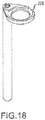
- System 201 further comprises a connection ring configured to move the integral posts (DC bus bar comprising an integral cup washer 228) outward radially such that the DC bus bar could be redesigned to minimize shear stresses between the bar and flag (with brief reference to FIG. 18 with integral wire support wall).
- system 101 comprises a wire support 120, a wire support fastener 127, and a DC connection 130.
- System 101 further comprises a balance weight 140 configured to counter balance the weight of the components on the other side of the face 110 of the rotor 100.
- the counter weight may be coupled to the rotor 100 by fasteners 145.
- system 101 comprises DC connection 130.
- the DC connection 130 of system 101 comprises a steel washer 132, wire cup washer 134, first insulator 133, Bellville washer 131, DC post 135, DC bus bar 510, and a second insulator 129, and a threaded DC post fastener housing 136.
- Wire 128 may be held in place between wire cup washer 134 and DC bus bar 510.
- Wire 128 may wrap around DC post 135 at location 121.
- a partial loop of wire 128 may be wrapped at least partially around DC post 135.
- Wire 128 may be positioned within a wire support 120.
- system 101 comprises wire support 120.
- Wire support 120 may comprise channels 150 and 152 configured to retain and orient wires 125, 128.
- System 101 comprises a wire support fastener 127.
- the wire support fastener 127 may be housed by and coupled to threaded wire support fastener housing 124.
- system 101 comprises balance weight 140.
- Balance weight 140 may be retained by balance weight fastener 145.
- a steel washer 142 may be positioned between a head of balance weight fastener 145 and balance weight 140.
- Balance weight fastener 145 may be housed in a threaded balance weight fastener housing 141.
- wire supports extending from the face 110 of the rotor 100 experience high radial loads. These high radial loads, may cause concerns and/or failure of the wire 128 to bus bar 510 coupling. Similarly, the axial loads on the balance weight 140 may be undesirably high.
- the fasteners 227, 230 of system 201 comprise minimized lengths of unsupported threaded fasteners lengths.
- the DC ring 280 of system 201 carries much of the radial load that would otherwise be experienced by the fastener 227, 230 shafts.
- DC ring 280 may be made from any material, however, in various embodiments, DC ring 280 is comprised of metal.
- DC ring 280 may comprise a substantially annular shape.
- DC ring 280 comprises one or more raised threaded stand-offs, such as stand-off 223, 236. Stand-off 223, 236 protrudes from a surface of DC ring 280.
- Threads of stand-off 223, 236 may similarly be located above a plane defined by the location where stand-off 223, 236 interfaces with and axially extends from a face of DC ring 280.
- Stand-off 223, 236 may be integrally in/on formed in DC ring 280.
- Stand-off 223, 236 may be configured to receive a shortened fastener 227, 230 (e.g. a fastener with a shaft that is shorter than the conventional fasteners). Stated another way, the threads of the fastener 227, 230 are located axially closer to the head of the bolt. Thus, the force of the radial load is largely experienced by the stand-off 223, 236 rather than the fastener 227, 230.
- System 201 comprises raised stand-offs having high strength configured to reduce the overhung moment load on any threaded fasteners, such as fasteners 227, 230.
- a DC coupling 230 of system 201 is depicted.
- a fastener 230, coupled to a disc spring/Bellville washer 256, coupled to a washer 232, such as a steel washer is depicted.
- a disc spring comprises a generally convex disc supported at the outer periphery by one force and an opposing force on the center of the disc.
- a disc spring may generate high force in a very short spring length and with minimal movement in response to being compressed.
- the steel washer 232 may apply force on an insulator 233, such as a torlon insulator.
- the thickness of the insulator 233 surrounding the fastener 230 may be increased as compared with conventional insulators, such as the insulators of system 101.
- a flange of the insulator 233 may apply force on a steel washer 234 located proximate a wire 225.
- the wire 225 may be positioned within a DC bus bar comprising an integral cup washer 228 (an additional depiction of cup washer 228 is shown in FIG. 18 ).
- a second insulator such as a TORLON (polyamide-imide) insulator, may be coupled to the DC bus bar.
- Steel washer 232 may substantially adjacent to raised stand-off 236.
- system 201 may eliminate and/or reduce the fastener 230 moment loads, such as a moment load experienced at operational speed.
- the wire cup washer 134 of system 101 is eliminated in system 201.
- Wire support fastener 227 may be inserted into and coupled to raised stand-off 223.
- Wire support fastener 227 may be threaded to interact with respective threading of raised stand-off 223.
- the head of wire support fastener 227 may apply force on a Bellville washer 256 which is coupled to a steel washer 257.
- the diameter of steel washer 257 is suitably large to overlap and apply force on wire cover 220.
- Wire cover 220 may be made from any suitable material; however, is preferably plastic. Wire cover 220 covers at least a portion of wire support 259 directly.
- wire cover 220 covers wire support 259 and protects oil from interacting with wire 224, 225.
- Wire support 259 comprises at least one channel 250, 252 to orient and retain a wire 224, 225.
- Wire support 259 is lower profile than prior art wire support 120 of system 101 (see FIGS. 1 and 10 ).
- wire support 120 comprises two levels of wires 125, 128 having channels 150, 152. Though they do not touch, these channels 150, 152 are located in a stacked orientation within wire support 120.
- Wire support 259 of system 201 carries a single level of wire 224, 225 (channels 250 and 252 are generally within the same radial plane). Wires 224, 225 may be positioned within channel 250 and channel 252 without obstruction.
- wires 224, 225 may comprise an annular loop 226 configured to mate with integral cup washer 228.
- system 201 may comprise an integral counter balance weight 240.
- counter balance weight 240 may be integrally formed as a portion of DC ring 280.
- the counterbalance need not be coupled to DC ring 280 through secondary fasteners.
- Fastener 260 may pass through a through hole in DC ring 280 and be received in housing 265 to couple DC ring 280 to rotor 200.
- Fastener 260 head may reside in a recess 266 of counter balance weight 240.
- Counter balance weight 240 of system 201 being integral to DC ring 280, eliminates fasteners, such as fastener 145 in system 101 as a point of failure or yield point.
- the mass of counter balance weight 240 is located away from the axis of rotation of rotor 200 (e.g. towards the distal edge of DC ring 280).
- Counter balance weight 240 is suitably sized to counter balance the elements opposite it on the rotor face 210.
- counter balance weight 240 is suitably sized and positioned to counter balance the mass of the wire support 259, wire cover 220 and DC coupling 230 elements.
- the wire support 259, DC coupling 230 and counter balance 240 may all be coupled to DC ring 280.
- DC ring 280 may form a continuous annular loop.
- System 201 provides minimized threaded connection bending stresses, eliminated radially unsupported plastic components, a reduced part count, improved design for manufacturing, and increased design robustness as compared to conventional structures, such as system 101.
- Integral standoffs, similar to stand-offs 223, 236, configured to support high speed rotor connections (and associated fasteners) may be implemented in any system subject to axial loads.
- an exciter system 501 having integral AC coupling stand-offs 730 is depicted.
- Stand-offs 730 may be integral to exciter hub 710.
- system 501 comprises a raised stand-off 730 configured to carry an increased percentage of the radial load, and reduce load carried by the bolt/fastener/AC coupling 720.
- system 501 comprises an integrated a stand-off 730 configured to locate the first thread of fastener 720 as close as possible to the head of the fastener 720. In this way, stand-off 730 carries the axial load instead of fastener 720 carrying the axial load.
- a modified bus bar flag 750 is implemented to interact with the AC coupling (see FIG. 24 ).
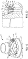
- FIG. 19 depicts a cross sectional view of the AC coupling of exciter system 501.
- Fastener 720 may be a button head screw.
- Fastener 720 may be coupled to a Belleville washer 710, NAS washer 715, and insulator 725.
- a bus bar having a flag 750 with increased diameter may be coupled to system 501.
- Insulator 745 may be coupled between bus bar flag 750 and exciter hub 710.
- FIG. 21 depicts a prior art exciter hub 610 used in prior art system 600.
- FIG. 23 depicts an exemplary exciter hub 710 of system 700.
- Exciter hub 710 comprises raised stand-offs 730.
- conventional systems such as system 600, may be retrofit with an adaptor configured to be inserted into fastener coupling points 630 and designed to receive a fastener, such as fastener 720 (not shown).
- the bus bar 640 flag 650 of system 600 may comprise a relatively narrow opening 655 to receive an AC coupling.
- the bus bar 740 flag 750 of system 501 may comprise an opening 755 configured to surround stand-off 730 and be coupled to the elements of AC coupling 720.
- references to "various embodiments”, “one embodiment”, “an embodiment”, “an example embodiment”, etc. indicate that the embodiment described may include a particular feature, structure, or characteristic, but every embodiment may not necessarily include the particular feature, structure, or characteristic. Moreover, such phrases are not necessarily referring to the same embodiment. Further, when a particular feature, structure, or characteristic is described in connection with an embodiment, it is submitted that it is within the knowledge of one skilled in the art to affect such feature, structure, or characteristic in connection with other embodiments whether or not explicitly described. After reading the description, it will be apparent to one skilled in the relevant art(s) how to implement the disclosure in alternative embodiments. Different cross-hatching is used throughout the figures to denote different parts but not necessarily to denote the same or different materials.
Landscapes
- Engineering & Computer Science (AREA)
- Power Engineering (AREA)
- Insulation, Fastening Of Motor, Generator Windings (AREA)
- Braking Arrangements (AREA)
- Applications Or Details Of Rotary Compressors (AREA)
Claims (14)
- Läuferverbindungsträger, umfassend:einen Läuferverbindungsring (280), umfassend einen mit Gewinde versehenen Drahtträgerbefestigungselement-Abstandspfosten (223)
wobei der mit Gewinde versehene Drahtträgerbefestigungselement-Abstandspfosten (223) Innengewinde umfasst; und
wobei sich zumindest ein Abschnitt des Innengewindes oberhalb einer Ebene befindet, die durch eine obere nach außen weisende Fläche des Läuferverbindungsrings (280) definiert ist;ein mit Außengewinde versehenes Drahtträgerbefestigungselement (127; 227); undeine Drahtabdeckung (220), wobei das Befestigungselement (127; 227) in den Drahtträgerbefestigungselement-Abstandspfosten (223) eingesetzt und mit diesem gekoppelt ist und die Drahtabdeckung (220) hält. - Läuferverbindungsträger nach Anspruch 1, wobei die Drahtabdeckung (220) so positioniert ist, dass sie einen Drahtträger (120; 259) zumindest teilweise überlappt.
- Läuferverbindungsträger nach Anspruch 2, wobei der Drahtträger (120; 259) einen Kanal (150, 152; 250, 252) zum Lenken der Ausrichtung eines Drahts (224, 225) umfasst.
- Läuferverbindungsträger nach Anspruch 2, wobei der Drahtträger (120; 259) ein Paar von Kanälen (150, 152; 250, 252) umfasst, die konfiguriert sind, um zwei unterschiedliche Drähte (125, 128; 224, 225) unterzubringen, wobei das Paar von Kanälen (150, 152; 250, 252) im Wesentlichen in derselben axialen Ebene ausgerichtet ist.
- Läuferverbindungsträger nach einem vorhergehenden Anspruch, wobei der Läuferverbindungsring (280) ferner ein integriertes Gegengewicht (140; 240) umfasst.
- Läuferverbindungsträger nach Anspruch 5, wobei das Gegengewicht (240) bemessen und positioniert ist, um zumindest ein Gewicht der Drahtabdeckung (220), des Drahtträgers (259) und eines mit Gewinde versehenen Gleichstromkopplers (230) auszugleichen.
- Läuferverbindungsträger nach einem vorhergehenden Anspruch, wobei der mit Gewinde versehene Drahtträgerbefestigungselement-Abstandspfosten (223) in den Läuferverbindungring (280) integriert ist.
- Läuferverbindungsträger nach einem vorhergehenden Anspruch, wobei der mit Gewinde versehene Drahtträgerbefestigungselement-Abstandspfosten (223) konfiguriert ist, um eine axiale Last aufzunehmen.
- Läuferverbindungsträger nach einem vorhergehenden Anspruch, ferner umfassend einen Gleichstromkoppler-Abstandspfosten (236) und eine Gleichstromschiene, wobei der Gleichstromkoppler-Abstandspfosten (236) Innengewinde umfasst, wobei sich zumindest ein Abschnitt des Innengewindes oberhalb der Ebene befindet, die durch die obere nach außen weisende Fläche des Verbindungsrings (280) definiert ist, und wobei die Gleichstromschiene eine integrierte Tellerscheibe (228) umfasst, die konfiguriert ist, um einen ringförmigen Draht zu halten, wobei die integrierte Tellerscheibe mit einem Draht gekoppelt ist, der konfiguriert ist, um über ein weiteres mit Gewinde versehenes Befestigungselement (230) gesichert zu werden.
- Gleichstromläufersystem (201), umfassend:
einen Läuferverbindungsträger (280) nach Anspruch 1. - Gleichstromläufersystem nach Anspruch 10, ferner umfassend mindestens eines aus:
einem Gegengewicht (240), das integriert im Verbindungsring (280) ausgebildet ist; und einem Gleichstromkoppler-Abstandspfosten (236), der mit einem weiteren mit Gewinde versehenen Befestigungselement (230) gekoppelt ist, wobei der Gleichstromkoppler-Abstandspfosten (236) Innengewinde umfasst, wobei sich zumindest ein Abschnitt des Innengewindes oberhalb der Ebene befindet, die durch die obere nach außen weisende Fläche des Verbindungsrings (280) definiert ist. - Gleichstromläufersystem nach Anspruch 10, ferner umfassend einen Gleichstromkoppler-Abstandspfosten (236), wobei der Gleichstromkoppler-Abstandspfosten (236) und der Drahtträgerbefestigungselement-Abstandshalter (223) konfiguriert sind, um mindestens eines aus axialen Lasten und radialen Lasten aufzunehmen.
- Gleichstromläufersystem nach Anspruch 11, ferner umfassend eine Gleichstromschiene (510; 640; 740), die eine integrierte Tellerscheibe (228) umfasst, die konfiguriert ist, um einen ringförmigen Draht (226) zu halten, der durch das weitere mit Gewinde versehene Befestigungselement (230) gesichert ist.
- Gleichstromläufersystem nach einem der Ansprüche 10 bis 13, ferner umfassend einen Drahtträger (120; 259), der durch die Drahtabdeckung (220) gehalten wird, wobei der Drahtträger (120; 259) ein Paar von Kanälen (150, 152; 250, 252) umfasst, die konfiguriert sind, um zwei unterschiedliche Drähte (125, 128; 224, 225) unterzubringen, wobei das Paar von Kanälen (150, 152; 250, 252) im Wesentlichen quer zur selben axialen Ebene ausgerichtet ist.
Applications Claiming Priority (2)
| Application Number | Priority Date | Filing Date | Title |
|---|---|---|---|
| US201361888341P | 2013-10-08 | 2013-10-08 | |
| US14/162,287 US9755472B2 (en) | 2013-10-08 | 2014-01-23 | High speed rotor connection support |
Publications (3)
| Publication Number | Publication Date |
|---|---|
| EP2863519A2 EP2863519A2 (de) | 2015-04-22 |
| EP2863519A3 EP2863519A3 (de) | 2016-06-01 |
| EP2863519B1 true EP2863519B1 (de) | 2018-09-26 |
Family
ID=51660371
Family Applications (1)
| Application Number | Title | Priority Date | Filing Date |
|---|---|---|---|
| EP14187870.2A Active EP2863519B1 (de) | 2013-10-08 | 2014-10-07 | Verbindungsträger eines Hochgeschwindigkeitsläufers |
Country Status (2)
| Country | Link |
|---|---|
| US (1) | US9755472B2 (de) |
| EP (1) | EP2863519B1 (de) |
Cited By (1)
| Publication number | Priority date | Publication date | Assignee | Title |
|---|---|---|---|---|
| DE102019200751A1 (de) * | 2019-01-22 | 2020-07-23 | Volkswagen Aktiengesellschaft | Kontaktierungsvorrichtung, Elektromotor und Verfahren zum Kontaktieren von Stromschienen miteinander in einem Elektromotor eines Kraftfahrzeuges |
Families Citing this family (3)
| Publication number | Priority date | Publication date | Assignee | Title |
|---|---|---|---|---|
| KR102579568B1 (ko) | 2015-11-12 | 2023-09-18 | 엘지이노텍 주식회사 | 버스바 및 이를 포함하는 모터 |
| DE102017216074A1 (de) * | 2016-10-14 | 2018-04-19 | Robert Bosch Gmbh | Elektromotor mit einem Klemmelement |
| US12230975B2 (en) * | 2022-06-03 | 2025-02-18 | Deere & Company | Assembly for contactless transfer of electrical energy to a rotor |
Family Cites Families (19)
| Publication number | Priority date | Publication date | Assignee | Title |
|---|---|---|---|---|
| US3542166A (en) | 1967-11-09 | 1970-11-24 | Girling Ltd | Brake disc and supporting means therefor |
| US4643513A (en) * | 1985-12-12 | 1987-02-17 | Martin Charles B | Universal electrical connector |
| DE10361859A1 (de) * | 2003-12-30 | 2005-08-11 | Robert Bosch Gmbh | Elektrische Maschine und dazu vorgesehener Ständer |
| DE102004050374B4 (de) | 2004-10-15 | 2010-11-11 | Minebea Co., Ltd. | Elektrische Maschine, insbesondere Gleichstrommotor |
| US9291227B2 (en) | 2005-09-30 | 2016-03-22 | Performance Friction Corporation | Brake rotor and abs tone ring attachment assembly that promotes in plane uniform torque transfer distribution |
| US7586224B2 (en) * | 2005-11-16 | 2009-09-08 | Hamilton Sundstrand Corporation | Rotating rectifier assembly |
| US8056684B2 (en) * | 2006-03-30 | 2011-11-15 | Kelsey-Hayes Company | Vehicle drum-in-hat disc brake assembly and method for producing same |
| US20080218035A1 (en) * | 2007-03-09 | 2008-09-11 | C.E. Niehoff & Co. | Rotating rectifier assembly |
| JP5186180B2 (ja) * | 2007-11-05 | 2013-04-17 | 株式会社ミツバ | ブラシレスモータ |
| JP4535146B2 (ja) * | 2008-02-27 | 2010-09-01 | 株式会社デンソー | コイルの固定部材及び回転電機 |
| US7868494B2 (en) * | 2008-08-26 | 2011-01-11 | Hamilton Sundstrand Corporation | Rectifier assembly |
| DE102008064159B3 (de) * | 2008-12-19 | 2010-01-28 | Bühler Motor GmbH | Elektronisch kommutierter Gleichstrommotor für eine Flüssigkeitspumpe |
| US8373318B2 (en) * | 2010-04-30 | 2013-02-12 | Hamilton Sundstrand Corporation | Terminal lead insulator assembly for wound field synchronous machine |
| CN201774430U (zh) * | 2010-07-29 | 2011-03-23 | 中山大洋电机制造有限公司 | 一种新型电机机构 |
| DE202010017081U1 (de) | 2010-08-16 | 2011-03-17 | Robert Bosch Gmbh | Kontakteinrichtung in einem Stator einer elektrischen Maschine |
| US8313351B2 (en) * | 2011-01-21 | 2012-11-20 | Hamilton Sundstrand Corporation | High altitude, high voltage terminal block assembly |
| US8950556B2 (en) | 2011-03-31 | 2015-02-10 | Gunite Corporation | Disk brake hub assembly |
| FR2984036B1 (fr) * | 2011-12-09 | 2014-08-08 | Michelin Soc Tech | Machine electrique avec connecteurs par contact |
| US9190888B2 (en) * | 2012-04-13 | 2015-11-17 | Globe Motors, Inc. | Method of positioning a sensor within a motor assembly |
-
2014
- 2014-01-23 US US14/162,287 patent/US9755472B2/en active Active
- 2014-10-07 EP EP14187870.2A patent/EP2863519B1/de active Active
Non-Patent Citations (1)
| Title |
|---|
| None * |
Cited By (1)
| Publication number | Priority date | Publication date | Assignee | Title |
|---|---|---|---|---|
| DE102019200751A1 (de) * | 2019-01-22 | 2020-07-23 | Volkswagen Aktiengesellschaft | Kontaktierungsvorrichtung, Elektromotor und Verfahren zum Kontaktieren von Stromschienen miteinander in einem Elektromotor eines Kraftfahrzeuges |
Also Published As
| Publication number | Publication date |
|---|---|
| EP2863519A3 (de) | 2016-06-01 |
| EP2863519A2 (de) | 2015-04-22 |
| US20150097464A1 (en) | 2015-04-09 |
| US9755472B2 (en) | 2017-09-05 |
Similar Documents
| Publication | Publication Date | Title |
|---|---|---|
| US10594198B2 (en) | Stator structure and resolver | |
| US9755472B2 (en) | High speed rotor connection support | |
| US8541924B2 (en) | Stator assembly having a phase-to-phase insulator, and a method of assembling a stator assembly | |
| EP2551998A1 (de) | Instrument zum hinzufügen eines temperaturfühlelements | |
| US8786159B2 (en) | Fixing structure for stator core and rotating electric machine including the same | |
| US20150076940A1 (en) | Rotary electric machine | |
| US20140021813A1 (en) | Elevator Drive | |
| US20030042818A1 (en) | System and method for end turn retention on a high speed generator rotor | |
| KR101555732B1 (ko) | 회전 전기 기계, 풍력 발전 시스템 및 회전 전기 기계 제조 방법 | |
| US8674566B2 (en) | Electrical machine with a device for monitoring an air gap between a rotor and a stator | |
| CN109519339A (zh) | 用于监测风力发电机的法兰联接机构的系统和方法 | |
| JP5306309B2 (ja) | 外転型の電動機 | |
| KR20210134941A (ko) | 전기 기계를 위한 상호 연결 조립체 및 스테이터 | |
| US10355551B2 (en) | Support element and stator assembly comprising the same | |
| US8405268B2 (en) | Stator with monolithic mounting bosses and assembly comprising the same | |
| EP3691090A1 (de) | Dynamo-elektrische maschine | |
| CN113991896B (zh) | 开关磁阻电机 | |
| US20100141084A1 (en) | Generator end turn stress reduction collar | |
| JP2005354847A (ja) | 回転駆動装置 | |
| US9966814B2 (en) | Motor having a fan cover that is latched to a foot plate, pump, and method for manufacturing the motor | |
| US20170358974A1 (en) | Rotary electric machine | |
| US8461742B2 (en) | Support system for dynamoelectric machine | |
| US11532964B2 (en) | Generator rotor flat wire winding | |
| US20160254720A1 (en) | Motor assembly | |
| US9518843B2 (en) | Flange and resolver assembly |
Legal Events
| Date | Code | Title | Description |
|---|---|---|---|
| PUAI | Public reference made under article 153(3) epc to a published international application that has entered the european phase |
Free format text: ORIGINAL CODE: 0009012 |
|
| 17P | Request for examination filed |
Effective date: 20141007 |
|
| AK | Designated contracting states |
Kind code of ref document: A2 Designated state(s): AL AT BE BG CH CY CZ DE DK EE ES FI FR GB GR HR HU IE IS IT LI LT LU LV MC MK MT NL NO PL PT RO RS SE SI SK SM TR |
|
| AX | Request for extension of the european patent |
Extension state: BA ME |
|
| PUAL | Search report despatched |
Free format text: ORIGINAL CODE: 0009013 |
|
| AK | Designated contracting states |
Kind code of ref document: A3 Designated state(s): AL AT BE BG CH CY CZ DE DK EE ES FI FR GB GR HR HU IE IS IT LI LT LU LV MC MK MT NL NO PL PT RO RS SE SI SK SM TR |
|
| AX | Request for extension of the european patent |
Extension state: BA ME |
|
| RIC1 | Information provided on ipc code assigned before grant |
Ipc: H02K 3/50 20060101AFI20160426BHEP |
|
| STAA | Information on the status of an ep patent application or granted ep patent |
Free format text: STATUS: REQUEST FOR EXAMINATION WAS MADE |
|
| R17P | Request for examination filed (corrected) |
Effective date: 20161201 |
|
| RBV | Designated contracting states (corrected) |
Designated state(s): AL AT BE BG CH CY CZ DE DK EE ES FI FR GB GR HR HU IE IS IT LI LT LU LV MC MK MT NL NO PL PT RO RS SE SI SK SM TR |
|
| R17P | Request for examination filed (corrected) |
Effective date: 20161201 |
|
| GRAP | Despatch of communication of intention to grant a patent |
Free format text: ORIGINAL CODE: EPIDOSNIGR1 |
|
| STAA | Information on the status of an ep patent application or granted ep patent |
Free format text: STATUS: GRANT OF PATENT IS INTENDED |
|
| INTG | Intention to grant announced |
Effective date: 20180412 |
|
| GRAS | Grant fee paid |
Free format text: ORIGINAL CODE: EPIDOSNIGR3 |
|
| GRAA | (expected) grant |
Free format text: ORIGINAL CODE: 0009210 |
|
| STAA | Information on the status of an ep patent application or granted ep patent |
Free format text: STATUS: THE PATENT HAS BEEN GRANTED |
|
| AK | Designated contracting states |
Kind code of ref document: B1 Designated state(s): AL AT BE BG CH CY CZ DE DK EE ES FI FR GB GR HR HU IE IS IT LI LT LU LV MC MK MT NL NO PL PT RO RS SE SI SK SM TR |
|
| REG | Reference to a national code |
Ref country code: GB Ref legal event code: FG4D |
|
| REG | Reference to a national code |
Ref country code: CH Ref legal event code: EP |
|
| REG | Reference to a national code |
Ref country code: AT Ref legal event code: REF Ref document number: 1047181 Country of ref document: AT Kind code of ref document: T Effective date: 20181015 |
|
| REG | Reference to a national code |
Ref country code: IE Ref legal event code: FG4D |
|
| REG | Reference to a national code |
Ref country code: FR Ref legal event code: PLFP Year of fee payment: 5 |
|
| REG | Reference to a national code |
Ref country code: DE Ref legal event code: R096 Ref document number: 602014032922 Country of ref document: DE |
|
| REG | Reference to a national code |
Ref country code: NL Ref legal event code: MP Effective date: 20180926 |
|
| PG25 | Lapsed in a contracting state [announced via postgrant information from national office to epo] |
Ref country code: GR Free format text: LAPSE BECAUSE OF FAILURE TO SUBMIT A TRANSLATION OF THE DESCRIPTION OR TO PAY THE FEE WITHIN THE PRESCRIBED TIME-LIMIT Effective date: 20181227 Ref country code: NO Free format text: LAPSE BECAUSE OF FAILURE TO SUBMIT A TRANSLATION OF THE DESCRIPTION OR TO PAY THE FEE WITHIN THE PRESCRIBED TIME-LIMIT Effective date: 20181226 Ref country code: LT Free format text: LAPSE BECAUSE OF FAILURE TO SUBMIT A TRANSLATION OF THE DESCRIPTION OR TO PAY THE FEE WITHIN THE PRESCRIBED TIME-LIMIT Effective date: 20180926 Ref country code: BG Free format text: LAPSE BECAUSE OF FAILURE TO SUBMIT A TRANSLATION OF THE DESCRIPTION OR TO PAY THE FEE WITHIN THE PRESCRIBED TIME-LIMIT Effective date: 20181226 Ref country code: RS Free format text: LAPSE BECAUSE OF FAILURE TO SUBMIT A TRANSLATION OF THE DESCRIPTION OR TO PAY THE FEE WITHIN THE PRESCRIBED TIME-LIMIT Effective date: 20180926 Ref country code: SE Free format text: LAPSE BECAUSE OF FAILURE TO SUBMIT A TRANSLATION OF THE DESCRIPTION OR TO PAY THE FEE WITHIN THE PRESCRIBED TIME-LIMIT Effective date: 20180926 Ref country code: FI Free format text: LAPSE BECAUSE OF FAILURE TO SUBMIT A TRANSLATION OF THE DESCRIPTION OR TO PAY THE FEE WITHIN THE PRESCRIBED TIME-LIMIT Effective date: 20180926 |
|
| REG | Reference to a national code |
Ref country code: LT Ref legal event code: MG4D |
|
| PG25 | Lapsed in a contracting state [announced via postgrant information from national office to epo] |
Ref country code: AL Free format text: LAPSE BECAUSE OF FAILURE TO SUBMIT A TRANSLATION OF THE DESCRIPTION OR TO PAY THE FEE WITHIN THE PRESCRIBED TIME-LIMIT Effective date: 20180926 Ref country code: HR Free format text: LAPSE BECAUSE OF FAILURE TO SUBMIT A TRANSLATION OF THE DESCRIPTION OR TO PAY THE FEE WITHIN THE PRESCRIBED TIME-LIMIT Effective date: 20180926 Ref country code: LV Free format text: LAPSE BECAUSE OF FAILURE TO SUBMIT A TRANSLATION OF THE DESCRIPTION OR TO PAY THE FEE WITHIN THE PRESCRIBED TIME-LIMIT Effective date: 20180926 |
|
| REG | Reference to a national code |
Ref country code: AT Ref legal event code: MK05 Ref document number: 1047181 Country of ref document: AT Kind code of ref document: T Effective date: 20180926 |
|
| PG25 | Lapsed in a contracting state [announced via postgrant information from national office to epo] |
Ref country code: PL Free format text: LAPSE BECAUSE OF FAILURE TO SUBMIT A TRANSLATION OF THE DESCRIPTION OR TO PAY THE FEE WITHIN THE PRESCRIBED TIME-LIMIT Effective date: 20180926 Ref country code: EE Free format text: LAPSE BECAUSE OF FAILURE TO SUBMIT A TRANSLATION OF THE DESCRIPTION OR TO PAY THE FEE WITHIN THE PRESCRIBED TIME-LIMIT Effective date: 20180926 Ref country code: AT Free format text: LAPSE BECAUSE OF FAILURE TO SUBMIT A TRANSLATION OF THE DESCRIPTION OR TO PAY THE FEE WITHIN THE PRESCRIBED TIME-LIMIT Effective date: 20180926 Ref country code: IT Free format text: LAPSE BECAUSE OF FAILURE TO SUBMIT A TRANSLATION OF THE DESCRIPTION OR TO PAY THE FEE WITHIN THE PRESCRIBED TIME-LIMIT Effective date: 20180926 Ref country code: NL Free format text: LAPSE BECAUSE OF FAILURE TO SUBMIT A TRANSLATION OF THE DESCRIPTION OR TO PAY THE FEE WITHIN THE PRESCRIBED TIME-LIMIT Effective date: 20180926 Ref country code: CZ Free format text: LAPSE BECAUSE OF FAILURE TO SUBMIT A TRANSLATION OF THE DESCRIPTION OR TO PAY THE FEE WITHIN THE PRESCRIBED TIME-LIMIT Effective date: 20180926 Ref country code: IS Free format text: LAPSE BECAUSE OF FAILURE TO SUBMIT A TRANSLATION OF THE DESCRIPTION OR TO PAY THE FEE WITHIN THE PRESCRIBED TIME-LIMIT Effective date: 20190126 Ref country code: RO Free format text: LAPSE BECAUSE OF FAILURE TO SUBMIT A TRANSLATION OF THE DESCRIPTION OR TO PAY THE FEE WITHIN THE PRESCRIBED TIME-LIMIT Effective date: 20180926 Ref country code: ES Free format text: LAPSE BECAUSE OF FAILURE TO SUBMIT A TRANSLATION OF THE DESCRIPTION OR TO PAY THE FEE WITHIN THE PRESCRIBED TIME-LIMIT Effective date: 20180926 |
|
| REG | Reference to a national code |
Ref country code: DE Ref legal event code: R119 Ref document number: 602014032922 Country of ref document: DE |
|
| PG25 | Lapsed in a contracting state [announced via postgrant information from national office to epo] |
Ref country code: SK Free format text: LAPSE BECAUSE OF FAILURE TO SUBMIT A TRANSLATION OF THE DESCRIPTION OR TO PAY THE FEE WITHIN THE PRESCRIBED TIME-LIMIT Effective date: 20180926 Ref country code: PT Free format text: LAPSE BECAUSE OF FAILURE TO SUBMIT A TRANSLATION OF THE DESCRIPTION OR TO PAY THE FEE WITHIN THE PRESCRIBED TIME-LIMIT Effective date: 20190126 Ref country code: SM Free format text: LAPSE BECAUSE OF FAILURE TO SUBMIT A TRANSLATION OF THE DESCRIPTION OR TO PAY THE FEE WITHIN THE PRESCRIBED TIME-LIMIT Effective date: 20180926 |
|
| REG | Reference to a national code |
Ref country code: CH Ref legal event code: PL |
|
| REG | Reference to a national code |
Ref country code: BE Ref legal event code: MM Effective date: 20181031 |
|
| PG25 | Lapsed in a contracting state [announced via postgrant information from national office to epo] |
Ref country code: LU Free format text: LAPSE BECAUSE OF NON-PAYMENT OF DUE FEES Effective date: 20181007 |
|
| REG | Reference to a national code |
Ref country code: IE Ref legal event code: MM4A |
|
| PG25 | Lapsed in a contracting state [announced via postgrant information from national office to epo] |
Ref country code: DE Free format text: LAPSE BECAUSE OF NON-PAYMENT OF DUE FEES Effective date: 20190501 Ref country code: MC Free format text: LAPSE BECAUSE OF FAILURE TO SUBMIT A TRANSLATION OF THE DESCRIPTION OR TO PAY THE FEE WITHIN THE PRESCRIBED TIME-LIMIT Effective date: 20180926 Ref country code: DK Free format text: LAPSE BECAUSE OF FAILURE TO SUBMIT A TRANSLATION OF THE DESCRIPTION OR TO PAY THE FEE WITHIN THE PRESCRIBED TIME-LIMIT Effective date: 20180926 |
|
| PLBE | No opposition filed within time limit |
Free format text: ORIGINAL CODE: 0009261 |
|
| STAA | Information on the status of an ep patent application or granted ep patent |
Free format text: STATUS: NO OPPOSITION FILED WITHIN TIME LIMIT |
|
| PG25 | Lapsed in a contracting state [announced via postgrant information from national office to epo] |
Ref country code: LI Free format text: LAPSE BECAUSE OF NON-PAYMENT OF DUE FEES Effective date: 20181031 Ref country code: CH Free format text: LAPSE BECAUSE OF NON-PAYMENT OF DUE FEES Effective date: 20181031 Ref country code: BE Free format text: LAPSE BECAUSE OF NON-PAYMENT OF DUE FEES Effective date: 20181031 |
|
| 26N | No opposition filed |
Effective date: 20190627 |
|
| PG25 | Lapsed in a contracting state [announced via postgrant information from national office to epo] |
Ref country code: SI Free format text: LAPSE BECAUSE OF FAILURE TO SUBMIT A TRANSLATION OF THE DESCRIPTION OR TO PAY THE FEE WITHIN THE PRESCRIBED TIME-LIMIT Effective date: 20180926 Ref country code: IE Free format text: LAPSE BECAUSE OF NON-PAYMENT OF DUE FEES Effective date: 20181007 |
|
| PG25 | Lapsed in a contracting state [announced via postgrant information from national office to epo] |
Ref country code: MT Free format text: LAPSE BECAUSE OF NON-PAYMENT OF DUE FEES Effective date: 20181007 |
|
| PG25 | Lapsed in a contracting state [announced via postgrant information from national office to epo] |
Ref country code: TR Free format text: LAPSE BECAUSE OF FAILURE TO SUBMIT A TRANSLATION OF THE DESCRIPTION OR TO PAY THE FEE WITHIN THE PRESCRIBED TIME-LIMIT Effective date: 20180926 |
|
| PG25 | Lapsed in a contracting state [announced via postgrant information from national office to epo] |
Ref country code: HU Free format text: LAPSE BECAUSE OF FAILURE TO SUBMIT A TRANSLATION OF THE DESCRIPTION OR TO PAY THE FEE WITHIN THE PRESCRIBED TIME-LIMIT; INVALID AB INITIO Effective date: 20141007 Ref country code: CY Free format text: LAPSE BECAUSE OF FAILURE TO SUBMIT A TRANSLATION OF THE DESCRIPTION OR TO PAY THE FEE WITHIN THE PRESCRIBED TIME-LIMIT Effective date: 20180926 Ref country code: MK Free format text: LAPSE BECAUSE OF NON-PAYMENT OF DUE FEES Effective date: 20180926 |
|
| P01 | Opt-out of the competence of the unified patent court (upc) registered |
Effective date: 20230522 |
|
| PGFP | Annual fee paid to national office [announced via postgrant information from national office to epo] |
Ref country code: GB Payment date: 20250923 Year of fee payment: 12 |
|
| PGFP | Annual fee paid to national office [announced via postgrant information from national office to epo] |
Ref country code: FR Payment date: 20250924 Year of fee payment: 12 |