EP2863486A1 - Socket-shaped housing, connector, and connector arrangement with cable support - Google Patents
Socket-shaped housing, connector, and connector arrangement with cable support Download PDFInfo
- Publication number
- EP2863486A1 EP2863486A1 EP20140189014 EP14189014A EP2863486A1 EP 2863486 A1 EP2863486 A1 EP 2863486A1 EP 20140189014 EP20140189014 EP 20140189014 EP 14189014 A EP14189014 A EP 14189014A EP 2863486 A1 EP2863486 A1 EP 2863486A1
- Authority
- EP
- European Patent Office
- Prior art keywords
- connector
- cable
- housing
- cable support
- support
- Prior art date
- Legal status (The legal status is an assumption and is not a legal conclusion. Google has not performed a legal analysis and makes no representation as to the accuracy of the status listed.)
- Granted
Links
Images


Classifications
-
- H—ELECTRICITY
- H01—ELECTRIC ELEMENTS
- H01R—ELECTRICALLY-CONDUCTIVE CONNECTIONS; STRUCTURAL ASSOCIATIONS OF A PLURALITY OF MUTUALLY-INSULATED ELECTRICAL CONNECTING ELEMENTS; COUPLING DEVICES; CURRENT COLLECTORS
- H01R13/00—Details of coupling devices of the kinds covered by groups H01R12/70 or H01R24/00 - H01R33/00
- H01R13/46—Bases; Cases
- H01R13/533—Bases, cases made for use in extreme conditions, e.g. high temperature, radiation, vibration, corrosive environment, pressure
-
- H—ELECTRICITY
- H01—ELECTRIC ELEMENTS
- H01R—ELECTRICALLY-CONDUCTIVE CONNECTIONS; STRUCTURAL ASSOCIATIONS OF A PLURALITY OF MUTUALLY-INSULATED ELECTRICAL CONNECTING ELEMENTS; COUPLING DEVICES; CURRENT COLLECTORS
- H01R13/00—Details of coupling devices of the kinds covered by groups H01R12/70 or H01R24/00 - H01R33/00
- H01R13/40—Securing contact members in or to a base or case; Insulating of contact members
- H01R13/42—Securing in a demountable manner
- H01R13/426—Securing by a separate resilient retaining piece supported by base or case, e.g. collar or metal contact-retention clip
-
- H—ELECTRICITY
- H01—ELECTRIC ELEMENTS
- H01R—ELECTRICALLY-CONDUCTIVE CONNECTIONS; STRUCTURAL ASSOCIATIONS OF A PLURALITY OF MUTUALLY-INSULATED ELECTRICAL CONNECTING ELEMENTS; COUPLING DEVICES; CURRENT COLLECTORS
- H01R13/00—Details of coupling devices of the kinds covered by groups H01R12/70 or H01R24/00 - H01R33/00
- H01R13/46—Bases; Cases
- H01R13/516—Means for holding or embracing insulating body, e.g. casing, hoods
-
- H—ELECTRICITY
- H01—ELECTRIC ELEMENTS
- H01R—ELECTRICALLY-CONDUCTIVE CONNECTIONS; STRUCTURAL ASSOCIATIONS OF A PLURALITY OF MUTUALLY-INSULATED ELECTRICAL CONNECTING ELEMENTS; COUPLING DEVICES; CURRENT COLLECTORS
- H01R13/00—Details of coupling devices of the kinds covered by groups H01R12/70 or H01R24/00 - H01R33/00
- H01R13/58—Means for relieving strain on wire connection, e.g. cord grip, for avoiding loosening of connections between wires and terminals within a coupling device terminating a cable
- H01R13/5804—Means for relieving strain on wire connection, e.g. cord grip, for avoiding loosening of connections between wires and terminals within a coupling device terminating a cable comprising a separate cable clamping part
- H01R13/5812—Means for relieving strain on wire connection, e.g. cord grip, for avoiding loosening of connections between wires and terminals within a coupling device terminating a cable comprising a separate cable clamping part the cable clamping being achieved by mounting the separate part on the housing of the coupling device
-
- H—ELECTRICITY
- H01—ELECTRIC ELEMENTS
- H01R—ELECTRICALLY-CONDUCTIVE CONNECTIONS; STRUCTURAL ASSOCIATIONS OF A PLURALITY OF MUTUALLY-INSULATED ELECTRICAL CONNECTING ELEMENTS; COUPLING DEVICES; CURRENT COLLECTORS
- H01R13/00—Details of coupling devices of the kinds covered by groups H01R12/70 or H01R24/00 - H01R33/00
- H01R13/58—Means for relieving strain on wire connection, e.g. cord grip, for avoiding loosening of connections between wires and terminals within a coupling device terminating a cable
- H01R13/582—Means for relieving strain on wire connection, e.g. cord grip, for avoiding loosening of connections between wires and terminals within a coupling device terminating a cable the cable being clamped between assembled parts of the housing
-
- H—ELECTRICITY
- H01—ELECTRIC ELEMENTS
- H01R—ELECTRICALLY-CONDUCTIVE CONNECTIONS; STRUCTURAL ASSOCIATIONS OF A PLURALITY OF MUTUALLY-INSULATED ELECTRICAL CONNECTING ELEMENTS; COUPLING DEVICES; CURRENT COLLECTORS
- H01R13/00—Details of coupling devices of the kinds covered by groups H01R12/70 or H01R24/00 - H01R33/00
- H01R13/58—Means for relieving strain on wire connection, e.g. cord grip, for avoiding loosening of connections between wires and terminals within a coupling device terminating a cable
- H01R13/582—Means for relieving strain on wire connection, e.g. cord grip, for avoiding loosening of connections between wires and terminals within a coupling device terminating a cable the cable being clamped between assembled parts of the housing
- H01R13/5825—Means for relieving strain on wire connection, e.g. cord grip, for avoiding loosening of connections between wires and terminals within a coupling device terminating a cable the cable being clamped between assembled parts of the housing the means comprising additional parts captured between housing parts and cable
-
- H—ELECTRICITY
- H01—ELECTRIC ELEMENTS
- H01R—ELECTRICALLY-CONDUCTIVE CONNECTIONS; STRUCTURAL ASSOCIATIONS OF A PLURALITY OF MUTUALLY-INSULATED ELECTRICAL CONNECTING ELEMENTS; COUPLING DEVICES; CURRENT COLLECTORS
- H01R13/00—Details of coupling devices of the kinds covered by groups H01R12/70 or H01R24/00 - H01R33/00
- H01R13/40—Securing contact members in or to a base or case; Insulating of contact members
- H01R13/42—Securing in a demountable manner
- H01R13/436—Securing a plurality of contact members by one locking piece or operation
- H01R13/4367—Insertion of locking piece from the rear
- H01R13/4368—Insertion of locking piece from the rear comprising a temporary and a final locking position
Definitions
- the invention concerns a socket-shape housing with a receptacle for attaching at least one completely mounted, standardised connector, attached to at least one cable, in the housing, having an attachment section for the attachment of the housing to a support.
- the invention further concerns a connector arrangement having a housing that includes a receptacle, in which at least one standardised connector, attached to at least one cable, is attached, and an attachment section for the attachment of the housing to a support.
- Housings and connector arrangements of this type are known, and are attached, e.g., to consoles of control cabinets or body components in automobile construction. Inside them, they receive a standardised plug, e.g., for power and/or data transfer, which is configured in accordance with an industrial or company standard.
- the plug is held in place by the housing attached to the support.
- the housing and the connector are used as a socket by putting together a mating plug having a complementary structure with the plug, usually on the side opposite the housing.
- the vibrations to which the housing, plug, and cable are exposed in operation constitute a problem.
- the vibrations result in a relative movement between the plug and the mating plug, resulting in wear to the electrical contacts over time due to friction oxidation or rubbing through.
- the invention seeks to take measures that will reduce the wear experienced by contacts in electrical plug connections.
- this problem is solved according to the invention by having a cable support in the receptacle directly supported by the housing, and by providing the separate cable support with at least one retaining hole in which the cable is held free of play.
- the cable support affixes the cable to the housing, which absorbs the vibrations.
- the connectors are preferably low-pole connectors with power contacts having cross-sections between 2.5 and 35 mm 2 .
- a connector configured so as to be able to be attached to at least one cable, with a separate cable support that has at least one retaining hole in order to hold the cable free of play on the cable support.
- the cable support extends into the cubage of the connector, and has at least one support element that is accessible from outside of the connector.
- the support element accessible from outside the connector can be used to affix the cable support directly in a housing. Additionally, in this configuration, the cable support affixes the connector indirectly to the housing.
- the housing, connector, and connector arrangement are based on the common idea of affixing the cable support direct to the housing in order to reduce movements of the cable relative to the housing.
- the housing and cable support can be provided with form fitting elements that complement one another.
- the cable support can thus be retained in the receptacle in a form-fitting manner.
- the form fit between the cable support and the housing or receptacle ensures a more solid and resilient connection that is capable of reliably absorbing even substantial vibrations.
- the support element of the cable support attached to the connector which is accessible from the outside and arranged in particular on the lateral surfaces, may be such a form-fitting element. This form-fitting element of the cable support may protrude from the connector according to another configuration.
- the form-fitting elements may from a linear guide along which the cable support can move from a cable-side end of the receptacle in the direction of the other end of the receptacle. This allows for simple insertion of the cable support into the receptacle from the cable-side opening.
- the form-fitting elements may be configured, e.g., as a tongue and groove arrangement that can be moved against one another along the receptacle.
- the complementary form-fitting elements may form a press fit, such that the form fit is augmented by a frictional connection.
- the form-fitting elements may have at least one stop, such that the cable support locks in place with the housing in a final position.
- the form-fitting elements may be located on a lateral surface on one of the narrow sides of the housing or connector.
- the cable support When mounted, the cable support is preferably on one end of the housing. On this end, it can lock the receptacle.
- the at least one form-fitting element may also be arranged on this end in the receptacle.
- the end of the housing with the cable support can be opposite the end with the attachment section with which the housing is attached to the support, and/or opposite the end in which the connector is supported by the housing.
- the cable support stabilises the cable in addition to the connector.
- the clear width of the retaining hole results preferably from the predetermined, normally standardised external diameter of the cable.
- the clear width of the retaining hole is somewhat smaller than the external diameter of the cable, resulting in a solid, non-slip press fit of the cable in the retaining hole because the insulation of the cable is somewhat crushed and the cable is affixed due to static friction between the cable support and the cable insulation.
- the cable is solidly clamped in the cable support. The clamping effect need not be due exclusively to the elasticity of the insulation layer of the cable.
- the cable support itself may be elastic, e.g., made of an elastically compressible material.
- the retaining hole of the cable support may be open on one side for lateral sliding onto a mounted cable, or be closed on all sides to be slid along the cable.
- locking closures may be provided to close a unilaterally open retaining hole.
- the form-fitting elements may be arranged on the ends of teeth delimiting the retaining hole. If the form-fitting elements are engaged with one another, the teeth may advantageously be deflected towards one another in order to clamp the cable more firmly.
- the cable support When mounted, the cable support may be arranged, in particular in the longitudinal direction of the cable, between a cable-side end of the connector and a plug-side end of the housing.
- the housing In this configuration, the housing is extended beyond the connector, and serves to support and protect the cable support.
- the housing In the area of the cable support the housing need not be closed on all sides, such that, in this position, the receptacle may be open towards one side, i.e., perpendicular to the longitudinal extent of the cables. This allows for material to be saved or the free space to be used for locking or another function.
- the cable support may have protrusions and/or recesses that engage with recessions of the connector.
- the protrusions advantageously extend in the direction of the longitudinal extent of the cables.
- the cable support may have a shroud or one or more other elements protruding between the cable and the connector.
- the cable support may be connected, or be able to connect, with the connector in a pre-mounted or pre-mountable unit that can be inserted into and/or removed from the housing as a unit.
- a structural combination of the cable support and the connector may be obtained if the cable support can be attached to the connector via one or more click-on connections.
- the retaining hole, but preferably the entire cable support may be inside the cubage of the connector.
- the cable support when mounted, it is in the connector, it may close an opening of the connector there, through which the cable reaches, to the outside.
- a form-fitting element of the cable support may protrude from the connector and engage with a complementary form-fitting element of the housing.
- the cable support may additionally be supported by the connector, such that it additionally affixes the connector and protects it from vibrations.
- the cable support may serve as a contact fuse.
- the cable support can only be moved into its final position when the contact element is properly mounted. This may be obtained, e.g., by positioning a barrier before the final position of the cable support in the path of the contact holder when the contact is not yet in its final position, which barrier is moved out of the path when the contact element is in its final position.
- the cable support may form a CPA (connector position assurance) of the connector that can only be received by the receptacle in one final position.
- CPA connector position assurance
- the cable support preferably consists of a single body, but may also consist of several rigidly connected individual bodies.
- the connector arrangement 1 has a housing 2 with a receptacle 3, in which a connector 4 and a cable support 5 are received.
- the housing 2 is socket-shaped and fastened to a support 6 (only shown schematically), e.g., a console or a body component.
- the attachment to the support 6 is provided by an attachment section 7, e.g., in the form of a flange that can be arranged on one end of the housing.
- the connector arrangement 1 thus forms a socket into which a mating plug (not shown) that complements the connector 3 can be inserted.
- the connector 3 is standardised and configured in accordance with an industry or company standard.
- the connector 3 is attached to at least one cable 8 and has at least one contact element not shown in fig. 1 , which is conductively connected with a lead 9 of the cable 7.
- Fig. 1 shows two cables by way of example only.
- the cable support 5 is arranged on a cable-side end 10 of the housing 2 in the receptacle 3.
- the receptacle 3 can be open not only on the cable-side end 10 of the housing 2, but also perpendicular to it, on one side.
- plug-side end 11 the receptacle may be laterally circumferentially closed and enclose the connector 4.
- the unilaterally open receptacle 3 on the cable-side end 10 is formed, e.g., by extending one part, here three, of the side walls 12 surrounding the receptacle 3 into a shroud.
- the connector 4 is inserted into the housing 2 in its completely assembled state, and locks in place there, e.g., by a unit 13.
- the at least one cable 9 is retained free of play, in particular, clamped, in a retaining hole 14.
- the receptacle 3 is closed on the cable end 10 by the cable support 5.
- the support as seen in the longitudinal direction 15 of the cable 8, is positioned between the cable end 10 of the housing 2 and the connector 3.
- the cable support 5 is directly supported by the housing 2, such that it prevents relative movement between the cables 9 and the housing 2. Thus, it absorbs vibrations that would otherwise be transferred via the at least one cable 9 to the connector 4 and could cause a relative movement there via the mating plug (not shown). Such a relative movement may result in increased wear of the contacts of the connector 4 and the mating plug.
- the connector 4 is not between the cable support 5 and the housing 2, such that it can be kept free of vibrations.
- Fig. 2 shows a cable support 5, the at least one retaining hole 14 of which is open laterally, such that it can be moved laterally, perpendicularly to the longitudinal direction 15 of the cables, onto the at least one cable 8, as indicated by the arrow 15.
- the cable support 5 can be inserted from the cable end 10 and/or the lateral opening 16 of the receptacle 3 into the housing 2.
- a clear width 17 of the retaining hole 14 is smaller than the external diameter 18 of the cable 8 at least when the cable support 5 is in the receptacle 3.
- an external insulation layer 19 of the cable which is generally somewhat resilient, is compressed such that the cable 8 is securely clamped in the retaining hole 14.
- the cable support 5 may be oversized compared to the receptacle 3, such that it and the retaining hole 14 are elastically pressed together when inserted.
- the cable support 5 itself may be arranged fully within the receptacle 3 with no play or at least with at least less play than the connector 4, and the retaining hole 14 may be elastically expanded by the cable 8, thus also resulting in secure clamping of the cable 8.
- the retaining hole 14 is closed on all sides, thus completely enclosing the cable 8.
- one end of the cable 8 must be guided through the hole 14 in order to mount the cable support 5 on the cable 8.
- the cable support 5 can be inserted into the receptacle 3 of the housing 2.
- the plug 4 can first be inserted into the housing 2, and the cable support 5 can then be moved along the at least one cable 8 into the receptacle 3.
- Fig. 3 also shows that the cable support 5 may have a form-fitting element 20.
- the housing 2 may have a form-fitting element 21 that complements the form-fitting element 20.
- the form-fitting elements 20, 21 may interact to form a linear guide along which the cable support 5 is guided movably into the receptacle 3 in the longitudinal direction 15 of the cable 8.
- the form-fitting elements 20, 21 are configured such that they allow for the cable support 5 to fit with little, or preferably no, play in the housing 2.
- the form-fitting elements 20, 21 may have a press fit.
- the form-fitting elements 20, 21 are configured in the form of a tongue and groove arrangement that allows for movement of the cable support along the direction of insertion 22 of the plug 4 into the housing 2 or in the direction of the longitudinal extent of the cable 8, whilst preventing movement in other directions.
- the form-fitting elements 20, 21 may contain catch means (not shown) with which the cable support 5 locks into place in the receptacle 3.
- the cable support 5 is pre-mounted on the connector 4, such that the two form a unit 23.
- the cable support 5 may, in particular, be arranged in the cubage of the connector 4 and close a cable-side opening 24 of the connector 4.
- the cable support 5 in this configuration also has at least one support or form-fitting element 20, supported in the receptacle 3 and/or directly engageable with the form-fitting element 21 of the housing 2.
- the support or form-fitting element 20 is accessible from the outside, in particular protrudes out of the connector 4.
- the connector 4 can have at least one additional form-fitting element 25 that interacts with the form-fitting element 20 or other form-fitting elements 26 of the cable support 5 and secures the cable support 5 on the connector 4.
- the form-fitting elements 20, 25, and/or 26 may form a linear guide for the cable support 5, along which the cable support 5 is at least partially guided movably into the connector 4 in the longitudinal direction 5 of the at least one cable 8.
- the form-fitting elements 20, 25, and/or 26 may additionally allow the cable support 5 to lock in place in the connector 4.
- the at least one cable 8 is directly affixed to the housing 2 via the cable support 5 although the cable support 5 is on the connector 4.
- the cable support 5 affixes the connector 4 on the cable end 10 of the housing both relative to the at least one cable 8 and to the housing 2. This results in a particularly rigid connection between the housing 2 and the connector 4.
- the cable support 5 and the connector 4 can also be assembled into a unit 23.
- the cable support 5 simultaneously also serves as a contact fuse by which the contact elements 27 are affixed in a contact chamber 28 of the connector 4.
- the cable support 5 can lock into place with the connector 4 in two locking positions. In the assembly position 29 shown in fig. 6 , the contact chamber 28 is released for complete insertion of the contact element 27 by the cable support 5.
- the contact elements 27 are directly or indirectly affixed in their final position by the cable support 5.
- the cable support 5 can only be transferred from the mounted position 29 into the operation position 30 when the contact elements 27 are in their final position 31 shown in fig. 8 .Before reaching the final position 31, the path of the cable support 5 from the assembly position 29 to the operating position 30 is blocked directly or indirectly by the contact element 27.
- the cable support 5 may thus serve as a CPA.
- the unit 23 of the embodiment of fig. 6 - 8 also has a form-fitting element 20 that is accessible from outside, in particular a protruding form-fitting element 20, with which the cable support 5 is supported in the receptacle 3.
- the connector 4 is always inserted along the receptacle into the housing from its cable end to its plug end.
- the connector it is also possible for the connector to be inserted into the housing 2 from the side. In this case, the housing 2 would be open on one side, both on the plug end 11 and on the cable end 10.
Landscapes
- Details Of Connecting Devices For Male And Female Coupling (AREA)
- Connector Housings Or Holding Contact Members (AREA)
Abstract
Description
- The invention concerns a socket-shape housing with a receptacle for attaching at least one completely mounted, standardised connector, attached to at least one cable, in the housing, having an attachment section for the attachment of the housing to a support.
- The invention further concerns a connector arrangement having a housing that includes a receptacle, in which at least one standardised connector, attached to at least one cable, is attached, and an attachment section for the attachment of the housing to a support.
- Housings and connector arrangements of this type are known, and are attached, e.g., to consoles of control cabinets or body components in automobile construction. Inside them, they receive a standardised plug, e.g., for power and/or data transfer, which is configured in accordance with an industrial or company standard. The plug is held in place by the housing attached to the support. The housing and the connector are used as a socket by putting together a mating plug having a complementary structure with the plug, usually on the side opposite the housing. By using a housing, it is possible to use the same type of plug regardless of whether a plug connection must be established between two ends of a cable or to a socket that is installed in a fixed fashion.
- In many applications, the vibrations to which the housing, plug, and cable are exposed in operation constitute a problem. The vibrations result in a relative movement between the plug and the mating plug, resulting in wear to the electrical contacts over time due to friction oxidation or rubbing through.
- The invention seeks to take measures that will reduce the wear experienced by contacts in electrical plug connections.
- This problem is solved by the aforementioned housing in that a separate cable support having at least one retaining hole to hold the cable free of play is provided, and that the cable support is supported directly by the housing in the receptacle.
- For the aforementioned connector configuration, this problem is solved according to the invention by having a cable support in the receptacle directly supported by the housing, and by providing the separate cable support with at least one retaining hole in which the cable is held free of play.
- This simple measure is able to reduce vibrations transferred to the connector via the cable. The cable support affixes the cable to the housing, which absorbs the vibrations.
- Compared to the conventional measure of attaching the cable support in or on the connector, as shown, e.g., in
DE 10 2009 032 393 A1EP 2 228 870 B1DE 10 2012 102 212 A1 - The connectors are preferably low-pole connectors with power contacts having cross-sections between 2.5 and 35 mm2.
- If modified connectors are used, the problem addressed by the invention is also solved by a connector configured so as to be able to be attached to at least one cable, with a separate cable support that has at least one retaining hole in order to hold the cable free of play on the cable support. The cable support extends into the cubage of the connector, and has at least one support element that is accessible from outside of the connector.
- The support element accessible from outside the connector can be used to affix the cable support directly in a housing. Additionally, in this configuration, the cable support affixes the connector indirectly to the housing.
- The housing, connector, and connector arrangement are based on the common idea of affixing the cable support direct to the housing in order to reduce movements of the cable relative to the housing.
- The solution of the invention can be further improved by the following further developments, each of which is advantageous independently and in itself, and which can be combined with one another as desired.
- Thus, according to a first advantageous configuration, the housing and cable support can be provided with form fitting elements that complement one another. The cable support can thus be retained in the receptacle in a form-fitting manner. The form fit between the cable support and the housing or receptacle ensures a more solid and resilient connection that is capable of reliably absorbing even substantial vibrations. The support element of the cable support attached to the connector, which is accessible from the outside and arranged in particular on the lateral surfaces, may be such a form-fitting element. This form-fitting element of the cable support may protrude from the connector according to another configuration. The form-fitting elements may from a linear guide along which the cable support can move from a cable-side end of the receptacle in the direction of the other end of the receptacle. This allows for simple insertion of the cable support into the receptacle from the cable-side opening. The form-fitting elements may be configured, e.g., as a tongue and groove arrangement that can be moved against one another along the receptacle. The complementary form-fitting elements may form a press fit, such that the form fit is augmented by a frictional connection.
- Lastly, the form-fitting elements may have at least one stop, such that the cable support locks in place with the housing in a final position.
- According to another configuration, the form-fitting elements may be located on a lateral surface on one of the narrow sides of the housing or connector.
- When mounted, the cable support is preferably on one end of the housing. On this end, it can lock the receptacle. The at least one form-fitting element may also be arranged on this end in the receptacle. In another configuration, the end of the housing with the cable support can be opposite the end with the attachment section with which the housing is attached to the support, and/or opposite the end in which the connector is supported by the housing. In the later case, the cable support stabilises the cable in addition to the connector.
- The clear width of the retaining hole results preferably from the predetermined, normally standardised external diameter of the cable. Preferably, the clear width of the retaining hole is somewhat smaller than the external diameter of the cable, resulting in a solid, non-slip press fit of the cable in the retaining hole because the insulation of the cable is somewhat crushed and the cable is affixed due to static friction between the cable support and the cable insulation. The cable is solidly clamped in the cable support. The clamping effect need not be due exclusively to the elasticity of the insulation layer of the cable. The cable support itself may be elastic, e.g., made of an elastically compressible material.
- The retaining hole of the cable support may be open on one side for lateral sliding onto a mounted cable, or be closed on all sides to be slid along the cable. To close a unilaterally open retaining hole, locking closures may be provided.
- The form-fitting elements may be arranged on the ends of teeth delimiting the retaining hole. If the form-fitting elements are engaged with one another, the teeth may advantageously be deflected towards one another in order to clamp the cable more firmly.
- When mounted, the cable support may be arranged, in particular in the longitudinal direction of the cable, between a cable-side end of the connector and a plug-side end of the housing. In this configuration, the housing is extended beyond the connector, and serves to support and protect the cable support. In the area of the cable support the housing need not be closed on all sides, such that, in this position, the receptacle may be open towards one side, i.e., perpendicular to the longitudinal extent of the cables. This allows for material to be saved or the free space to be used for locking or another function.
- In order to obtain a tighter fit between the connector and the cable support, the cable support may have protrusions and/or recesses that engage with recessions of the connector. The protrusions advantageously extend in the direction of the longitudinal extent of the cables. For example, the cable support may have a shroud or one or more other elements protruding between the cable and the connector.
- The cable support may be connected, or be able to connect, with the connector in a pre-mounted or pre-mountable unit that can be inserted into and/or removed from the housing as a unit. Such a structural combination of the cable support and the connector may be obtained if the cable support can be attached to the connector via one or more click-on connections. In particular, the retaining hole, but preferably the entire cable support, may be inside the cubage of the connector.
- If, when mounted, the cable support is in the connector, it may close an opening of the connector there, through which the cable reaches, to the outside.
- In order to obtain a direct form fit between the cable support and the receptacle, a form-fitting element of the cable support may protrude from the connector and engage with a complementary form-fitting element of the housing.
- If the cable support is attached to the connector arrangement, the cable support may additionally be supported by the connector, such that it additionally affixes the connector and protects it from vibrations.
- In another advantageous configuration, which is possible in particular in the presence of a cable support that can be connected with the connector to form a unit, the cable support may serve as a contact fuse. When put together, in this configuration, at least one electrical contact element connected with the cable is secured in a contact chamber of the plug connection by the cable support.
- In order to avoid improper assembly, in another configuration, the cable support can only be moved into its final position when the contact element is properly mounted. This may be obtained, e.g., by positioning a barrier before the final position of the cable support in the path of the contact holder when the contact is not yet in its final position, which barrier is moved out of the path when the contact element is in its final position.
- The cable support may form a CPA (connector position assurance) of the connector that can only be received by the receptacle in one final position.
- The cable support preferably consists of a single body, but may also consist of several rigidly connected individual bodies.
- The invention is explained below by way of example, based on various embodiments and by reference to the drawings. According to the above embodiments, the distinguishing characteristics of the various embodiments can be substituted and combined in any desired manner.
-
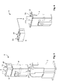
Fig. 1 shows a schematic perspective view of a first embodiment of a connector arrangement according to the invention with a housing, cable support, and connector; -
Fig. 2 shows a schematic perspective view of another embodiment of the connector arrangement before the insertion of the connector and cable support into the housing; -
Fig. 3 shows a schematic perspective view of another embodiment of the connector arrangement with the connector and cable support before being attached in the housing; -
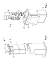
Fig. 4 shows a schematic representation of another embodiment of a connector with a cable support; -
Fig. 5 shows a schematic perspective view of the connector and the cable support offig. 4 with a housing; -
Fig. 6 shows a schematic perspective view of another embodiment of a connector with a cable support, cables, and contact elements before pre-assembly; -
Fig. 7 shows a schematic perspective view of the pre-mounted connector offig. 6 ; -
Fig. 8 shows a schematic perspective view of a section through the connector offig. 6 inserted into a housing. - First, the structure of a connector arrangement 1 according to the invention will be described based on
fig. 1 . The connector arrangement 1 has ahousing 2 with areceptacle 3, in which aconnector 4 and acable support 5 are received. - The
housing 2 is socket-shaped and fastened to a support 6 (only shown schematically), e.g., a console or a body component. The attachment to the support 6 is provided by anattachment section 7, e.g., in the form of a flange that can be arranged on one end of the housing. The connector arrangement 1 thus forms a socket into which a mating plug (not shown) that complements theconnector 3 can be inserted. Theconnector 3 is standardised and configured in accordance with an industry or company standard. Theconnector 3 is attached to at least onecable 8 and has at least one contact element not shown infig. 1 , which is conductively connected with alead 9 of thecable 7.Fig. 1 shows two cables by way of example only. - The
cable support 5 is arranged on a cable-side end 10 of thehousing 2 in thereceptacle 3. On this end, thereceptacle 3 can be open not only on the cable-side end 10 of thehousing 2, but also perpendicular to it, on one side. On the other, plug-side end 11, the receptacle may be laterally circumferentially closed and enclose theconnector 4. - The unilaterally
open receptacle 3 on the cable-side end 10 is formed, e.g., by extending one part, here three, of theside walls 12 surrounding thereceptacle 3 into a shroud. - The
connector 4 is inserted into thehousing 2 in its completely assembled state, and locks in place there, e.g., by aunit 13. - In the
cable support 5, the at least onecable 9 is retained free of play, in particular, clamped, in a retaininghole 14. Thereceptacle 3 is closed on thecable end 10 by thecable support 5. - In the embodiment shown in
fig. 1 , the support, as seen in thelongitudinal direction 15 of thecable 8, is positioned between thecable end 10 of thehousing 2 and theconnector 3. - The
cable support 5 is directly supported by thehousing 2, such that it prevents relative movement between thecables 9 and thehousing 2. Thus, it absorbs vibrations that would otherwise be transferred via the at least onecable 9 to theconnector 4 and could cause a relative movement there via the mating plug (not shown). Such a relative movement may result in increased wear of the contacts of theconnector 4 and the mating plug. Theconnector 4 is not between thecable support 5 and thehousing 2, such that it can be kept free of vibrations. - In the discussion of the other exemplary embodiments below, for the sake of simplicity, elements equivalent in structure and/or function will be given the same reference numerals as in the exemplary embodiment of
fig. 1 . For brevity's sake, the description is limited to the respective differences between the exemplary embodiments unless otherwise stated. -
Fig. 2 shows acable support 5, the at least one retaininghole 14 of which is open laterally, such that it can be moved laterally, perpendicularly to thelongitudinal direction 15 of the cables, onto the at least onecable 8, as indicated by thearrow 15. - The
cable support 5 can be inserted from thecable end 10 and/or thelateral opening 16 of thereceptacle 3 into thehousing 2. - A
clear width 17 of the retaininghole 14 is smaller than theexternal diameter 18 of thecable 8 at least when thecable support 5 is in thereceptacle 3. By undersizing the retaininghole 14, anexternal insulation layer 19 of the cable, which is generally somewhat resilient, is compressed such that thecable 8 is securely clamped in the retaininghole 14. Thecable support 5 may be oversized compared to thereceptacle 3, such that it and the retaininghole 14 are elastically pressed together when inserted. Alternatively, thecable support 5 itself may be arranged fully within thereceptacle 3 with no play or at least with at least less play than theconnector 4, and the retaininghole 14 may be elastically expanded by thecable 8, thus also resulting in secure clamping of thecable 8. - In the embodiment of
fig. 3 , the retaininghole 14 is closed on all sides, thus completely enclosing thecable 8. In this configuration, one end of thecable 8 must be guided through thehole 14 in order to mount thecable support 5 on thecable 8. Together with theconnector 4, thecable support 5 can be inserted into thereceptacle 3 of thehousing 2. Alternatively, theplug 4 can first be inserted into thehousing 2, and thecable support 5 can then be moved along the at least onecable 8 into thereceptacle 3. -
Fig. 3 also shows that thecable support 5 may have a form-fittingelement 20. Thehousing 2 may have a form-fittingelement 21 that complements the form-fittingelement 20. The form-fitting elements cable support 5 is guided movably into thereceptacle 3 in thelongitudinal direction 15 of thecable 8. The form-fitting elements cable support 5 to fit with little, or preferably no, play in thehousing 2. In particular, the form-fitting elements - In a simple configuration, the form-
fitting elements plug 4 into thehousing 2 or in the direction of the longitudinal extent of thecable 8, whilst preventing movement in other directions. - The form-
fitting elements cable support 5 locks into place in thereceptacle 3. - Das
wenigstens eine Formschlusselement 20 ist bevorzugt an einem Ende des Kabelhalters bzw. von dieHalteöffnung 14 begrenzenden Zinken 14' angeordnet. If the form-fitting elements clear width 17. - Another embodiment is shown schematically in
fig. 4 and5 . In this configuration, thecable support 5 is pre-mounted on theconnector 4, such that the two form aunit 23. Thecable support 5 may, in particular, be arranged in the cubage of theconnector 4 and close a cable-side opening 24 of theconnector 4. Thecable support 5 in this configuration also has at least one support or form-fittingelement 20, supported in thereceptacle 3 and/or directly engageable with the form-fittingelement 21 of thehousing 2. - This is achieved in that, in the
unit 23 consisting of theconnector 4 and the mountedcable support 5, the support or form-fittingelement 20 is accessible from the outside, in particular protrudes out of theconnector 4. - The
connector 4 can have at least one additional form-fittingelement 25 that interacts with the form-fittingelement 20 or other form-fitting elements 26 of thecable support 5 and secures thecable support 5 on theconnector 4. The form-fitting elements cable support 5, along which thecable support 5 is at least partially guided movably into theconnector 4 in thelongitudinal direction 5 of the at least onecable 8. The form-fitting elements cable support 5 to lock in place in theconnector 4. - In the exemplary embodiment of
fig. 4 and5 , the at least onecable 8 is directly affixed to thehousing 2 via thecable support 5 although thecable support 5 is on theconnector 4. Simultaneously, thecable support 5 affixes theconnector 4 on thecable end 10 of the housing both relative to the at least onecable 8 and to thehousing 2. This results in a particularly rigid connection between thehousing 2 and theconnector 4. - In the exemplary embodiment of
fig. 6 - 8 , thecable support 5 and theconnector 4 can also be assembled into aunit 23. However, thecable support 5 simultaneously also serves as a contact fuse by which thecontact elements 27 are affixed in acontact chamber 28 of theconnector 4. - The
cable support 5 can lock into place with theconnector 4 in two locking positions. In theassembly position 29 shown infig. 6 , thecontact chamber 28 is released for complete insertion of thecontact element 27 by thecable support 5. - In the second locking position, the operating position shown in
fig. 7 , thecontact elements 27 are directly or indirectly affixed in their final position by thecable support 5. Thecable support 5 can only be transferred from the mountedposition 29 into theoperation position 30 when thecontact elements 27 are in theirfinal position 31 shown infig. 8 .Before reaching thefinal position 31, the path of thecable support 5 from theassembly position 29 to theoperating position 30 is blocked directly or indirectly by thecontact element 27. Thecable support 5 may thus serve as a CPA. As with the exemplary embodiment offig. 4 and5 , theunit 23 of the embodiment offig. 6 - 8 also has a form-fittingelement 20 that is accessible from outside, in particular a protruding form-fittingelement 20, with which thecable support 5 is supported in thereceptacle 3. - In the above exemplary embodiments, the
connector 4 is always inserted along the receptacle into the housing from its cable end to its plug end. However, it is also possible for the connector to be inserted into thehousing 2 from the side. In this case, thehousing 2 would be open on one side, both on theplug end 11 and on thecable end 10. -
- 1
- Connector arrangement
- 2
- Housing
- 3
- Receptacle
- 4
- Connector
- 5
- Cable support
- 6
- Support
- 7
- Attachment section
- 8
- Cable
- 9
- Lead
- 10
- Cable end
- 11
- Plug end
- 12
- Side walls
- 13
- Locking unit for connector
- 14
- Retaining hole of cable support
- 14'
- Retaining hole teeth
- 15
- Longitudinal direction of the cable
- 16
- Side opening of the receptacle
- 17
- Clear width of the retaining hole
- 18
- External diameter of the cable
- 19
- Cable insulation
- 20
- Form-fitting element of cable support
- 21
- Form-fitting element of housing
- 22
- Plugging direction of the plug in the housing
- 23
- Unit comprising connector and cable support
- 24
- Cable-side opening of the connector
- 25
- Form-fitting element of connector
- 26
- Additional form-fitting element of cable support
- 27
- Contact element
- 28
- Contact chamber
- 29
- Assembly position of cable support
- 30
- Operating position of cable support
- 31
- Final position of contact elements
Claims (15)
- Socket-shaped housing (2) with a receptacle (3) for attaching at least one completely mounted, standardised connector (4), attached to at least one cable (8), in the housing, having an attachment section (7) for the attachment of the housing (2) to a support (6), characterised in that a separate cable support (5) having at least one retaining hole (14) to hold the cable free of play is provided, and that the cable support (5) is supported directly by the housing (2) in the receptacle (3).
- Housing (2) according to claim 1, characterised in that the cable support (5) and the receptacle (3) can be seen with form-fitting elements (20, 21) that complement one another.
- Housing (2) according to claim 2, characterised in that the form-fitting elements (20, 21) form a linear guide along which the cable support (5) can move from a cable-side end (10) of the receptacle (3) in the direction of the other end (11) of the receptacle (3).
- Connector (4) that is configured to be attachable to at least one cable (8), having a separate cable support (5), which has at least one retaining hole (14) to retain the cable (8) free of play on the cable support (5), characterised in that the cable support (5) extends into the cubage of the connector (4), and has at least one support element (20) that is accessible from outside of the connector (4).
- Connector (4) according to claim 4, characterised in that the support element (20) protrudes out of the connector (4).
- Connector (4) according to claim 4 or 5, characterised in that the cable support (5) secures at least one contact element (27) attached to the cable (8) in the connector (4).
- Connector arrangement (1) having a housing (2) that includes a receptacle (3), in which at least one standardised connector (4), attached to at least one cable (8), is attached, and an attachment section (7) for the attachment of the housing (2) to a support (6), characterised in that a cable support (5) in the receptacle (3) is directly supported by the housing (2) and that the cable support (5) has at least one retaining hole (14) in which the cable (8) is held free of play.
- Connector arrangement (1) according to claim 7, characterised in that the cable support (5) is held directly in the receptacle (3) in a form-fitting manner.
- Connector arrangement (1) according to claim 7 or 8, characterised in that the cable support (5) is arranged between the connector (4) and the cable end (10) of the housing (2).
- Connector arrangement (1) according to any of claims 7 - 9, characterised in that the cable support (5) along with the connector (4) can be inserted as a pre-assembled unit (23) into the housing (2).
- Connector arrangement (1) according to any of claims 7 - 10, characterised in that the at least one retaining hole (14) is inside the cubage of the connector (4).
- Connector arrangement (1) according to any of claims 7 - 11, characterised in that a form-fitting element (20) of the cable support (5) protrudes out of the connector (4) and engages with a complementary form-fitting element (22) of the housing (2).
- Connector arrangement (1) according to any of claims 7 - 12, characterised in that the form-fitting elements (20, 21) of the cable support (5) and the housing (2) form a linear guide along which the cable support (5) is movably guided into the receptacle (3).
- Connector arrangement (1) according to any of claims 7 - 13, characterised in that the cable support (5) closes the cable end (10) of the housing (2).
- Connector arrangement (1) according to any of claims 7 - 14, characterised in that the cable support (5) forms a CPA of the connector (4) that can only be received in the receptacle (3) in a final position (31) of the cable support (5).
Applications Claiming Priority (1)
| Application Number | Priority Date | Filing Date | Title |
|---|---|---|---|
| DE201310221339 DE102013221339A1 (en) | 2013-10-21 | 2013-10-21 | Socket-shaped housing, connector and connector assembly with cable holder |
Publications (2)
| Publication Number | Publication Date |
|---|---|
| EP2863486A1 true EP2863486A1 (en) | 2015-04-22 |
| EP2863486B1 EP2863486B1 (en) | 2020-10-07 |
Family
ID=51690968
Family Applications (1)
| Application Number | Title | Priority Date | Filing Date |
|---|---|---|---|
| EP14189014.5A Active EP2863486B1 (en) | 2013-10-21 | 2014-10-15 | Connector arrangement with cable support |
Country Status (6)
| Country | Link |
|---|---|
| US (2) | US9941625B2 (en) |
| EP (1) | EP2863486B1 (en) |
| JP (1) | JP6448124B2 (en) |
| CN (1) | CN104617436B (en) |
| DE (1) | DE102013221339A1 (en) |
| IN (1) | IN2014DE02906A (en) |
Families Citing this family (9)
| Publication number | Priority date | Publication date | Assignee | Title |
|---|---|---|---|---|
| US20150214662A1 (en) * | 2012-09-07 | 2015-07-30 | Yazaki Corporation | Connector affixation structure |
| DE102015201089A1 (en) * | 2015-01-22 | 2016-07-28 | Te Connectivity Germany Gmbh | Intermediate housing with a CPA receptacle and connector systems comprising such |
| DE202015103923U1 (en) * | 2015-07-27 | 2015-09-24 | HARTING Electronics GmbH | Electrical connector |
| EP3229324B1 (en) * | 2016-04-07 | 2019-05-08 | Signify Holding B.V. | Electrical cable retention |
| US9882317B1 (en) * | 2016-09-15 | 2018-01-30 | Te Connectivity Corporation | Connector system with hybrid electrical connectors |
| JP6792797B2 (en) * | 2017-03-01 | 2020-12-02 | 株式会社オートネットワーク技術研究所 | Terminal unit |
| DE102020126541B4 (en) * | 2020-10-09 | 2026-01-29 | Te Connectivity Germany Gmbh | Electrical plug and fixing device for fixing a contact element in a housing of the electrical plug |
| IT202100010583A1 (en) * | 2021-04-27 | 2022-10-27 | Te Connectivity Italia Distribution Srl | SYSTEM AND METHOD OF BLOCKING ELECTRICAL TERMINALS |
| US11923636B2 (en) * | 2021-09-10 | 2024-03-05 | Turck Inc. | Cable connector, cable connector arrangement and d-sub type cable connector |
Citations (7)
| Publication number | Priority date | Publication date | Assignee | Title |
|---|---|---|---|---|
| KR100623503B1 (en) * | 2006-06-30 | 2006-09-15 | (주)에이프러스 씨엠 건축사사무소 | Outlet plug and plug with waterproof structure |
| WO2010068291A1 (en) * | 2008-12-12 | 2010-06-17 | Tyco Electronics Corporation | Connector assembly with strain relief |
| WO2011003914A1 (en) * | 2009-07-08 | 2011-01-13 | Tyco Electronics Amp Gmbh | Electrical plug connector having a one-piece connector housing and assembly method |
| EP2228870B1 (en) | 2009-03-12 | 2011-06-29 | Tyco Electronics AMP GmbH | Electrical connector |
| DE102011051951A1 (en) * | 2011-07-19 | 2013-01-24 | Phoenix Contact Gmbh & Co. Kg | Plug connector e.g. RJ-45 connector, for e.g. low current applications in electronic appliance, has locking elements latched into each other, so that locking elements lead away cable to cable working portions on housing |
| WO2013120936A1 (en) * | 2012-02-17 | 2013-08-22 | Tyco Electronics Amp Gmbh | Housing for a contact device |
| DE102012102212A1 (en) | 2012-03-15 | 2013-09-19 | Tyco Electronics Amp Gmbh | Plug for plug connector for automobile, has cable fixing unit and plug region spaced at distance from each other by forming mating plug retainer, and cable fixing unit rigidly connected with plug region by spacer |
Family Cites Families (15)
| Publication number | Priority date | Publication date | Assignee | Title |
|---|---|---|---|---|
| US3873172A (en) * | 1971-12-17 | 1975-03-25 | Amp Inc | Flat multi-conductor cable holder |
| US4108527A (en) * | 1977-06-23 | 1978-08-22 | Amp Incorporated | Strain relief assembly |
| JPS62149175U (en) * | 1986-03-13 | 1987-09-21 | ||
| JPH0418987U (en) * | 1990-06-04 | 1992-02-18 | ||
| JP2603233Y2 (en) * | 1993-02-01 | 2000-03-06 | 住友電装株式会社 | Retainer |
| US5720629A (en) * | 1996-10-16 | 1998-02-24 | The Whitaker Corporation | Sealed electrical connector |
| JP2000323226A (en) * | 1999-03-09 | 2000-11-24 | Sumitomo Wiring Syst Ltd | Connector |
| US6582248B2 (en) * | 2001-11-29 | 2003-06-24 | Neutrik Ag | Durable RJ-45 data connector assembly |
| JP2004185918A (en) * | 2002-12-02 | 2004-07-02 | Sumitomo Wiring Syst Ltd | Waterproof connector |
| JP4097589B2 (en) * | 2003-10-30 | 2008-06-11 | 日本航空電子工業株式会社 | Cable connector |
| JP5682997B2 (en) * | 2010-04-05 | 2015-03-11 | 日本圧着端子製造株式会社 | Electrical connector |
| DE102010029670A1 (en) * | 2010-06-02 | 2011-12-08 | Tyco Electronics Amp Gmbh | Connector assembly for an electrical connector, electrical connector and prefabricated electrical cable |
| US20120015541A1 (en) * | 2010-07-15 | 2012-01-19 | Juniper Networks, Inc. | Self-securing power cord |
| US8702444B2 (en) * | 2010-10-18 | 2014-04-22 | Panduit Corp. | Communication plug with improved cable manager |
| CN203233004U (en) * | 2013-05-13 | 2013-10-09 | 马玉荣 | Network connector for industrial-field communication device |
-
2013
- 2013-10-21 DE DE201310221339 patent/DE102013221339A1/en not_active Ceased
-
2014
- 2014-10-10 IN IN2906DE2014 patent/IN2014DE02906A/en unknown
- 2014-10-15 EP EP14189014.5A patent/EP2863486B1/en active Active
- 2014-10-21 CN CN201410858136.6A patent/CN104617436B/en active Active
- 2014-10-21 JP JP2014214099A patent/JP6448124B2/en active Active
- 2014-10-21 US US14/519,922 patent/US9941625B2/en active Active
-
2018
- 2018-02-28 US US15/908,148 patent/US10892584B2/en active Active
Patent Citations (8)
| Publication number | Priority date | Publication date | Assignee | Title |
|---|---|---|---|---|
| KR100623503B1 (en) * | 2006-06-30 | 2006-09-15 | (주)에이프러스 씨엠 건축사사무소 | Outlet plug and plug with waterproof structure |
| WO2010068291A1 (en) * | 2008-12-12 | 2010-06-17 | Tyco Electronics Corporation | Connector assembly with strain relief |
| EP2228870B1 (en) | 2009-03-12 | 2011-06-29 | Tyco Electronics AMP GmbH | Electrical connector |
| WO2011003914A1 (en) * | 2009-07-08 | 2011-01-13 | Tyco Electronics Amp Gmbh | Electrical plug connector having a one-piece connector housing and assembly method |
| DE102009032393A1 (en) | 2009-07-08 | 2011-01-13 | Tyco Electronics Amp Gmbh | Electrical connector with one-piece connector housing and mounting method |
| DE102011051951A1 (en) * | 2011-07-19 | 2013-01-24 | Phoenix Contact Gmbh & Co. Kg | Plug connector e.g. RJ-45 connector, for e.g. low current applications in electronic appliance, has locking elements latched into each other, so that locking elements lead away cable to cable working portions on housing |
| WO2013120936A1 (en) * | 2012-02-17 | 2013-08-22 | Tyco Electronics Amp Gmbh | Housing for a contact device |
| DE102012102212A1 (en) | 2012-03-15 | 2013-09-19 | Tyco Electronics Amp Gmbh | Plug for plug connector for automobile, has cable fixing unit and plug region spaced at distance from each other by forming mating plug retainer, and cable fixing unit rigidly connected with plug region by spacer |
Also Published As
| Publication number | Publication date |
|---|---|
| US20150111405A1 (en) | 2015-04-23 |
| US9941625B2 (en) | 2018-04-10 |
| US20180191100A1 (en) | 2018-07-05 |
| JP2015111555A (en) | 2015-06-18 |
| EP2863486B1 (en) | 2020-10-07 |
| CN104617436A (en) | 2015-05-13 |
| DE102013221339A1 (en) | 2015-04-23 |
| IN2014DE02906A (en) | 2015-06-26 |
| CN104617436B (en) | 2019-05-10 |
| US10892584B2 (en) | 2021-01-12 |
| JP6448124B2 (en) | 2019-01-09 |
Similar Documents
| Publication | Publication Date | Title |
|---|---|---|
| EP2863486B1 (en) | Connector arrangement with cable support | |
| EP3145035B1 (en) | Arrangement for establishing an electrical connection between a tab contact and a high current conductor | |
| CN107437680B (en) | Connecting cage for connecting two electrical flat contacts | |
| US9142904B2 (en) | Electrical connector with terminal position assurance | |
| US10276980B2 (en) | Connector with a CPA receiving space and connector assembly comprising such a connector | |
| US11228139B2 (en) | Plug connector of an electrical plug connection and set comprising a plug connector and functional element | |
| KR101580746B1 (en) | Connector | |
| US10847924B2 (en) | Contact device and contact system | |
| EP3457501A1 (en) | A connector housing comprising a cover | |
| WO2013178773A1 (en) | Electrical connector | |
| US9761961B2 (en) | Lead-through terminal | |
| US20110312208A1 (en) | Push-in connector for accepting the end of a rigid conductor | |
| KR20210123397A (en) | protective conductor connection | |
| CN103138064A (en) | Connecting device for ribbon cable, and electrical device with ribbon cable | |
| US9735505B2 (en) | Housing device for an electrical connection terminal and electrical connection terminal | |
| US6287153B1 (en) | Cable connector with improved engagement mechanism | |
| CN114336132B (en) | Fixing device for fixing a contact element in a housing of a connector | |
| EP2846416B1 (en) | Connector housing with a monolithically integrated terminal positioning assurance device | |
| IL273975B1 (en) | Multipart housing for consumption meters and a securing device for multipart housings | |
| CN104350646B (en) | Connector | |
| KR20210093355A (en) | Plug connector parts for connection in multiple spatial directions | |
| WO2015098883A1 (en) | Connector terminal holding structure | |
| US11569605B2 (en) | Contact device and contact system | |
| US10141672B2 (en) | Latching means for plug contacts | |
| KR102496262B1 (en) | Terminal structure for junction block |
Legal Events
| Date | Code | Title | Description |
|---|---|---|---|
| PUAI | Public reference made under article 153(3) epc to a published international application that has entered the european phase |
Free format text: ORIGINAL CODE: 0009012 |
|
| 17P | Request for examination filed |
Effective date: 20141015 |
|
| AK | Designated contracting states |
Kind code of ref document: A1 Designated state(s): AL AT BE BG CH CY CZ DE DK EE ES FI FR GB GR HR HU IE IS IT LI LT LU LV MC MK MT NL NO PL PT RO RS SE SI SK SM TR |
|
| AX | Request for extension of the european patent |
Extension state: BA ME |
|
| RAP1 | Party data changed (applicant data changed or rights of an application transferred) |
Owner name: TE CONNECTIVITY GERMANY GMBH |
|
| R17P | Request for examination filed (corrected) |
Effective date: 20151022 |
|
| RBV | Designated contracting states (corrected) |
Designated state(s): AL AT BE BG CH CY CZ DE DK EE ES FI FR GB GR HR HU IE IS IT LI LT LU LV MC MK MT NL NO PL PT RO RS SE SI SK SM TR |
|
| 17Q | First examination report despatched |
Effective date: 20160330 |
|
| STAA | Information on the status of an ep patent application or granted ep patent |
Free format text: STATUS: EXAMINATION IS IN PROGRESS |
|
| GRAP | Despatch of communication of intention to grant a patent |
Free format text: ORIGINAL CODE: EPIDOSNIGR1 |
|
| STAA | Information on the status of an ep patent application or granted ep patent |
Free format text: STATUS: GRANT OF PATENT IS INTENDED |
|
| RIC1 | Information provided on ipc code assigned before grant |
Ipc: H01R 13/516 20060101ALI20191115BHEP Ipc: H01R 13/58 20060101AFI20191115BHEP Ipc: H01R 13/533 20060101ALI20191115BHEP Ipc: H01R 13/436 20060101ALN20191115BHEP |
|
| RIC1 | Information provided on ipc code assigned before grant |
Ipc: H01R 13/516 20060101ALI20191126BHEP Ipc: H01R 13/58 20060101AFI20191126BHEP Ipc: H01R 13/533 20060101ALI20191126BHEP Ipc: H01R 13/436 20060101ALN20191126BHEP |
|
| INTG | Intention to grant announced |
Effective date: 20191211 |
|
| GRAJ | Information related to disapproval of communication of intention to grant by the applicant or resumption of examination proceedings by the epo deleted |
Free format text: ORIGINAL CODE: EPIDOSDIGR1 |
|
| STAA | Information on the status of an ep patent application or granted ep patent |
Free format text: STATUS: EXAMINATION IS IN PROGRESS |
|
| GRAP | Despatch of communication of intention to grant a patent |
Free format text: ORIGINAL CODE: EPIDOSNIGR1 |
|
| STAA | Information on the status of an ep patent application or granted ep patent |
Free format text: STATUS: GRANT OF PATENT IS INTENDED |
|
| INTC | Intention to grant announced (deleted) | ||
| RIC1 | Information provided on ipc code assigned before grant |
Ipc: H01R 13/516 20060101ALI20200414BHEP Ipc: H01R 13/436 20060101ALN20200414BHEP Ipc: H01R 13/58 20060101AFI20200414BHEP Ipc: H01R 13/533 20060101ALI20200414BHEP |
|
| INTG | Intention to grant announced |
Effective date: 20200506 |
|
| RIC1 | Information provided on ipc code assigned before grant |
Ipc: H01R 13/436 20060101ALN20200423BHEP Ipc: H01R 13/516 20060101ALI20200423BHEP Ipc: H01R 13/533 20060101ALI20200423BHEP Ipc: H01R 13/58 20060101AFI20200423BHEP |
|
| GRAS | Grant fee paid |
Free format text: ORIGINAL CODE: EPIDOSNIGR3 |
|
| GRAA | (expected) grant |
Free format text: ORIGINAL CODE: 0009210 |
|
| STAA | Information on the status of an ep patent application or granted ep patent |
Free format text: STATUS: THE PATENT HAS BEEN GRANTED |
|
| AK | Designated contracting states |
Kind code of ref document: B1 Designated state(s): AL AT BE BG CH CY CZ DE DK EE ES FI FR GB GR HR HU IE IS IT LI LT LU LV MC MK MT NL NO PL PT RO RS SE SI SK SM TR |
|
| REG | Reference to a national code |
Ref country code: GB Ref legal event code: FG4D |
|
| REG | Reference to a national code |
Ref country code: AT Ref legal event code: REF Ref document number: 1322165 Country of ref document: AT Kind code of ref document: T Effective date: 20201015 Ref country code: CH Ref legal event code: EP |
|
| REG | Reference to a national code |
Ref country code: IE Ref legal event code: FG4D |
|
| REG | Reference to a national code |
Ref country code: DE Ref legal event code: R096 Ref document number: 602014070933 Country of ref document: DE |
|
| REG | Reference to a national code |
Ref country code: NL Ref legal event code: MP Effective date: 20201007 |
|
| REG | Reference to a national code |
Ref country code: AT Ref legal event code: MK05 Ref document number: 1322165 Country of ref document: AT Kind code of ref document: T Effective date: 20201007 |
|
| PG25 | Lapsed in a contracting state [announced via postgrant information from national office to epo] |
Ref country code: NL Free format text: LAPSE BECAUSE OF FAILURE TO SUBMIT A TRANSLATION OF THE DESCRIPTION OR TO PAY THE FEE WITHIN THE PRESCRIBED TIME-LIMIT Effective date: 20201007 Ref country code: NO Free format text: LAPSE BECAUSE OF FAILURE TO SUBMIT A TRANSLATION OF THE DESCRIPTION OR TO PAY THE FEE WITHIN THE PRESCRIBED TIME-LIMIT Effective date: 20210107 Ref country code: PT Free format text: LAPSE BECAUSE OF FAILURE TO SUBMIT A TRANSLATION OF THE DESCRIPTION OR TO PAY THE FEE WITHIN THE PRESCRIBED TIME-LIMIT Effective date: 20210208 Ref country code: FI Free format text: LAPSE BECAUSE OF FAILURE TO SUBMIT A TRANSLATION OF THE DESCRIPTION OR TO PAY THE FEE WITHIN THE PRESCRIBED TIME-LIMIT Effective date: 20201007 Ref country code: RS Free format text: LAPSE BECAUSE OF FAILURE TO SUBMIT A TRANSLATION OF THE DESCRIPTION OR TO PAY THE FEE WITHIN THE PRESCRIBED TIME-LIMIT Effective date: 20201007 Ref country code: GR Free format text: LAPSE BECAUSE OF FAILURE TO SUBMIT A TRANSLATION OF THE DESCRIPTION OR TO PAY THE FEE WITHIN THE PRESCRIBED TIME-LIMIT Effective date: 20210108 |
|
| REG | Reference to a national code |
Ref country code: LT Ref legal event code: MG4D |
|
| PG25 | Lapsed in a contracting state [announced via postgrant information from national office to epo] |
Ref country code: IS Free format text: LAPSE BECAUSE OF FAILURE TO SUBMIT A TRANSLATION OF THE DESCRIPTION OR TO PAY THE FEE WITHIN THE PRESCRIBED TIME-LIMIT Effective date: 20210207 Ref country code: PL Free format text: LAPSE BECAUSE OF FAILURE TO SUBMIT A TRANSLATION OF THE DESCRIPTION OR TO PAY THE FEE WITHIN THE PRESCRIBED TIME-LIMIT Effective date: 20201007 Ref country code: SE Free format text: LAPSE BECAUSE OF FAILURE TO SUBMIT A TRANSLATION OF THE DESCRIPTION OR TO PAY THE FEE WITHIN THE PRESCRIBED TIME-LIMIT Effective date: 20201007 Ref country code: LV Free format text: LAPSE BECAUSE OF FAILURE TO SUBMIT A TRANSLATION OF THE DESCRIPTION OR TO PAY THE FEE WITHIN THE PRESCRIBED TIME-LIMIT Effective date: 20201007 Ref country code: AT Free format text: LAPSE BECAUSE OF FAILURE TO SUBMIT A TRANSLATION OF THE DESCRIPTION OR TO PAY THE FEE WITHIN THE PRESCRIBED TIME-LIMIT Effective date: 20201007 Ref country code: ES Free format text: LAPSE BECAUSE OF FAILURE TO SUBMIT A TRANSLATION OF THE DESCRIPTION OR TO PAY THE FEE WITHIN THE PRESCRIBED TIME-LIMIT Effective date: 20201007 Ref country code: BG Free format text: LAPSE BECAUSE OF FAILURE TO SUBMIT A TRANSLATION OF THE DESCRIPTION OR TO PAY THE FEE WITHIN THE PRESCRIBED TIME-LIMIT Effective date: 20210107 |
|
| REG | Reference to a national code |
Ref country code: CH Ref legal event code: PL |
|
| PG25 | Lapsed in a contracting state [announced via postgrant information from national office to epo] |
Ref country code: HR Free format text: LAPSE BECAUSE OF FAILURE TO SUBMIT A TRANSLATION OF THE DESCRIPTION OR TO PAY THE FEE WITHIN THE PRESCRIBED TIME-LIMIT Effective date: 20201007 Ref country code: LU Free format text: LAPSE BECAUSE OF NON-PAYMENT OF DUE FEES Effective date: 20201015 |
|
| REG | Reference to a national code |
Ref country code: DE Ref legal event code: R097 Ref document number: 602014070933 Country of ref document: DE |
|
| REG | Reference to a national code |
Ref country code: BE Ref legal event code: MM Effective date: 20201031 |
|
| PG25 | Lapsed in a contracting state [announced via postgrant information from national office to epo] |
Ref country code: RO Free format text: LAPSE BECAUSE OF FAILURE TO SUBMIT A TRANSLATION OF THE DESCRIPTION OR TO PAY THE FEE WITHIN THE PRESCRIBED TIME-LIMIT Effective date: 20201007 Ref country code: SK Free format text: LAPSE BECAUSE OF FAILURE TO SUBMIT A TRANSLATION OF THE DESCRIPTION OR TO PAY THE FEE WITHIN THE PRESCRIBED TIME-LIMIT Effective date: 20201007 Ref country code: LT Free format text: LAPSE BECAUSE OF FAILURE TO SUBMIT A TRANSLATION OF THE DESCRIPTION OR TO PAY THE FEE WITHIN THE PRESCRIBED TIME-LIMIT Effective date: 20201007 Ref country code: MC Free format text: LAPSE BECAUSE OF FAILURE TO SUBMIT A TRANSLATION OF THE DESCRIPTION OR TO PAY THE FEE WITHIN THE PRESCRIBED TIME-LIMIT Effective date: 20201007 Ref country code: SM Free format text: LAPSE BECAUSE OF FAILURE TO SUBMIT A TRANSLATION OF THE DESCRIPTION OR TO PAY THE FEE WITHIN THE PRESCRIBED TIME-LIMIT Effective date: 20201007 Ref country code: CZ Free format text: LAPSE BECAUSE OF FAILURE TO SUBMIT A TRANSLATION OF THE DESCRIPTION OR TO PAY THE FEE WITHIN THE PRESCRIBED TIME-LIMIT Effective date: 20201007 Ref country code: EE Free format text: LAPSE BECAUSE OF FAILURE TO SUBMIT A TRANSLATION OF THE DESCRIPTION OR TO PAY THE FEE WITHIN THE PRESCRIBED TIME-LIMIT Effective date: 20201007 |
|
| PLBE | No opposition filed within time limit |
Free format text: ORIGINAL CODE: 0009261 |
|
| STAA | Information on the status of an ep patent application or granted ep patent |
Free format text: STATUS: NO OPPOSITION FILED WITHIN TIME LIMIT |
|
| PG25 | Lapsed in a contracting state [announced via postgrant information from national office to epo] |
Ref country code: DK Free format text: LAPSE BECAUSE OF FAILURE TO SUBMIT A TRANSLATION OF THE DESCRIPTION OR TO PAY THE FEE WITHIN THE PRESCRIBED TIME-LIMIT Effective date: 20201007 Ref country code: CH Free format text: LAPSE BECAUSE OF NON-PAYMENT OF DUE FEES Effective date: 20201031 Ref country code: BE Free format text: LAPSE BECAUSE OF NON-PAYMENT OF DUE FEES Effective date: 20201031 Ref country code: LI Free format text: LAPSE BECAUSE OF NON-PAYMENT OF DUE FEES Effective date: 20201031 |
|
| 26N | No opposition filed |
Effective date: 20210708 |
|
| GBPC | Gb: european patent ceased through non-payment of renewal fee |
Effective date: 20210107 |
|
| PG25 | Lapsed in a contracting state [announced via postgrant information from national office to epo] |
Ref country code: AL Free format text: LAPSE BECAUSE OF FAILURE TO SUBMIT A TRANSLATION OF THE DESCRIPTION OR TO PAY THE FEE WITHIN THE PRESCRIBED TIME-LIMIT Effective date: 20201007 Ref country code: IE Free format text: LAPSE BECAUSE OF NON-PAYMENT OF DUE FEES Effective date: 20201015 |
|
| PG25 | Lapsed in a contracting state [announced via postgrant information from national office to epo] |
Ref country code: GB Free format text: LAPSE BECAUSE OF NON-PAYMENT OF DUE FEES Effective date: 20210107 Ref country code: SI Free format text: LAPSE BECAUSE OF FAILURE TO SUBMIT A TRANSLATION OF THE DESCRIPTION OR TO PAY THE FEE WITHIN THE PRESCRIBED TIME-LIMIT Effective date: 20201007 |
|
| PG25 | Lapsed in a contracting state [announced via postgrant information from national office to epo] |
Ref country code: IS Free format text: LAPSE BECAUSE OF FAILURE TO SUBMIT A TRANSLATION OF THE DESCRIPTION OR TO PAY THE FEE WITHIN THE PRESCRIBED TIME-LIMIT Effective date: 20210207 Ref country code: TR Free format text: LAPSE BECAUSE OF FAILURE TO SUBMIT A TRANSLATION OF THE DESCRIPTION OR TO PAY THE FEE WITHIN THE PRESCRIBED TIME-LIMIT Effective date: 20201007 Ref country code: MT Free format text: LAPSE BECAUSE OF FAILURE TO SUBMIT A TRANSLATION OF THE DESCRIPTION OR TO PAY THE FEE WITHIN THE PRESCRIBED TIME-LIMIT Effective date: 20201007 Ref country code: CY Free format text: LAPSE BECAUSE OF FAILURE TO SUBMIT A TRANSLATION OF THE DESCRIPTION OR TO PAY THE FEE WITHIN THE PRESCRIBED TIME-LIMIT Effective date: 20201007 |
|
| PG25 | Lapsed in a contracting state [announced via postgrant information from national office to epo] |
Ref country code: MK Free format text: LAPSE BECAUSE OF FAILURE TO SUBMIT A TRANSLATION OF THE DESCRIPTION OR TO PAY THE FEE WITHIN THE PRESCRIBED TIME-LIMIT Effective date: 20201007 |
|
| PGFP | Annual fee paid to national office [announced via postgrant information from national office to epo] |
Ref country code: IT Payment date: 20250922 Year of fee payment: 12 |
|
| PGFP | Annual fee paid to national office [announced via postgrant information from national office to epo] |
Ref country code: FR Payment date: 20250908 Year of fee payment: 12 |
|
| PGFP | Annual fee paid to national office [announced via postgrant information from national office to epo] |
Ref country code: DE Payment date: 20250902 Year of fee payment: 12 |