EP2863475B1 - Radarwellenleiteranordnung - Google Patents
Radarwellenleiteranordnung Download PDFInfo
- Publication number
- EP2863475B1 EP2863475B1 EP13189519.5A EP13189519A EP2863475B1 EP 2863475 B1 EP2863475 B1 EP 2863475B1 EP 13189519 A EP13189519 A EP 13189519A EP 2863475 B1 EP2863475 B1 EP 2863475B1
- Authority
- EP
- European Patent Office
- Prior art keywords
- radar wave
- guiding arrangement
- wave guiding
- radar
- arrangement according
- Prior art date
- Legal status (The legal status is an assumption and is not a legal conclusion. Google has not performed a legal analysis and makes no representation as to the accuracy of the status listed.)
- Active
Links
Images


Classifications
-
- H—ELECTRICITY
- H01—ELECTRIC ELEMENTS
- H01Q—ANTENNAS, i.e. RADIO AERIALS
- H01Q1/00—Details of, or arrangements associated with, antennas
- H01Q1/42—Housings not intimately mechanically associated with radiating elements, e.g. radome
-
- G—PHYSICS
- G01—MEASURING; TESTING
- G01S—RADIO DIRECTION-FINDING; RADIO NAVIGATION; DETERMINING DISTANCE OR VELOCITY BY USE OF RADIO WAVES; LOCATING OR PRESENCE-DETECTING BY USE OF THE REFLECTION OR RERADIATION OF RADIO WAVES; ANALOGOUS ARRANGEMENTS USING OTHER WAVES
- G01S13/00—Systems using the reflection or reradiation of radio waves, e.g. radar systems; Analogous systems using reflection or reradiation of waves whose nature or wavelength is irrelevant or unspecified
- G01S13/88—Radar or analogous systems specially adapted for specific applications
- G01S13/93—Radar or analogous systems specially adapted for specific applications for anti-collision purposes
- G01S13/931—Radar or analogous systems specially adapted for specific applications for anti-collision purposes of land vehicles
-
- H—ELECTRICITY
- H01—ELECTRIC ELEMENTS
- H01Q—ANTENNAS, i.e. RADIO AERIALS
- H01Q1/00—Details of, or arrangements associated with, antennas
- H01Q1/27—Adaptation for use in or on movable bodies
- H01Q1/32—Adaptation for use in or on road or rail vehicles
- H01Q1/325—Adaptation for use in or on road or rail vehicles characterised by the location of the antenna on the vehicle
- H01Q1/3275—Adaptation for use in or on road or rail vehicles characterised by the location of the antenna on the vehicle mounted on a horizontal surface of the vehicle, e.g. on roof, hood, trunk
-
- H—ELECTRICITY
- H01—ELECTRIC ELEMENTS
- H01Q—ANTENNAS, i.e. RADIO AERIALS
- H01Q1/00—Details of, or arrangements associated with, antennas
- H01Q1/27—Adaptation for use in or on movable bodies
- H01Q1/32—Adaptation for use in or on road or rail vehicles
- H01Q1/325—Adaptation for use in or on road or rail vehicles characterised by the location of the antenna on the vehicle
- H01Q1/3283—Adaptation for use in or on road or rail vehicles characterised by the location of the antenna on the vehicle side-mounted antennas, e.g. bumper-mounted, door-mounted
-
- H—ELECTRICITY
- H01—ELECTRIC ELEMENTS
- H01Q—ANTENNAS, i.e. RADIO AERIALS
- H01Q13/00—Waveguide horns or mouths; Slot antennas; Leaky-waveguide antennas; Equivalent structures causing radiation along the transmission path of a guided wave
- H01Q13/02—Waveguide horns
-
- H—ELECTRICITY
- H01—ELECTRIC ELEMENTS
- H01Q—ANTENNAS, i.e. RADIO AERIALS
- H01Q19/00—Combinations of primary active antenna elements and units with secondary devices, e.g. with quasi-optical devices, for giving the antenna a desired directional characteristic
- H01Q19/06—Combinations of primary active antenna elements and units with secondary devices, e.g. with quasi-optical devices, for giving the antenna a desired directional characteristic using refracting or diffracting devices, e.g. lens
- H01Q19/08—Combinations of primary active antenna elements and units with secondary devices, e.g. with quasi-optical devices, for giving the antenna a desired directional characteristic using refracting or diffracting devices, e.g. lens for modifying the radiation pattern of a radiating horn in which it is located
Definitions
- the invention relates to radar wave guiding arrangements, and particularly to a radar wave guiding arrangement for a vehicle radar system.
- a horn antenna also known as microwave horn, or cone antenna
- a horn antenna is an antenna that consists of a flaring metal waveguide shaped like a horn to direct radio waves in a beam.
- Horns are widely used as antennas at ultra-high frequencies (UHF) and microwave frequencies, above 300 MHz.
- Horn antennas may further be used as feeders (called feed horns) for larger antenna structures, such as parabolic antennas, as standard calibration antennas to measure the gain of other antennas, and as directive antennas for such devices as radar guns, automatic door openers, and microwave radiometers.
- US 2012/0206312 A1 discloses a horn antenna with a dielectric filling body.
- US 2012/0206312 A1 discloses a horn antenna for a radar device.
- the horn antenna comprises a metal body containing a tubular hollow waveguide section which opens into a hollow horn section.
- a dielectric filling body fills up the inner space of the horn section.
- a dielectric cover is provided to surround the metal body and to cover the filling body at the aperture of the horn section as a protective covering for the horn antenna.
- US 2012/0206312 A1 One object of US 2012/0206312 A1 is to provide a horn antenna that is configured to be arranged so as to protrude in a measurement environment, protected from highly aggressive process environments and usable over a wide temperature range of, e.g., -40° C. to +80° C.
- the horn antenna US 2012/0206312 A1 has an elongated shape, i.e., the length (as defined in the longitudinal direction of the horn antenna) is larger than the width (as defined in the transversal direction of the horn antenna). It is thus cumbersome to place such a horn antenna in a vehicle, such as an automotive vehicle, where available space is scarce.
- the invention is defined in claim 1.
- An object of embodiments herein is to provide an improved radar wave guiding arrangement comprising a horn antenna.
- the inventor of the enclosed embodiments has through a combination of practical experimentation and theoretical derivation realized that by simply changing the dimensions of the horn antenna so as to make the horn antenna less elongated and thus more compact could negatively affect the directional properties of the radar wave guiding arrangement.
- a particular object is therefore to provide a radar wave guiding arrangement comprising a horn antenna and having a compact shape but still showing desired directional properties.
- a radar wave guiding arrangement for a vehicle radar system comprises a horn-shaped housing.
- the housing comprises first walls enclosing a cavity.
- the radar wave guiding arrangement comprises a dielectric insert.
- the dielectric insert comprises second walls and is positioned inside the cavity.
- the first walls and the second walls form at least one waveguide channel for guiding radar waves through the horn-shaped housing.
- the insert and the at least one waveguide channel have different wave distribution characteristics.
- this provides an improved radar wave guiding arrangement comprising a horn antenna.
- this provides a compact radar wave guiding arrangement comprising a horn antenna showing desired directional properties.
- the radar wave guiding arrangement provides a broad angle radiation in azimuth, at least ⁇ 70° from the longitudinal axis of the radar wave guiding arrangement, whilst still having a shallow shape.
- an automotive vehicle comprising a radar wave guiding arrangement according to the first aspect. It is to be noted that any feature of the first and second aspects may be applied to any other aspect, wherever appropriate. Likewise, any advantage of the first aspect may equally apply to the second aspect, respectively, and vice versa. Other objectives, features and advantages of the enclosed embodiments will be apparent from the following detailed disclosure, from the attached dependent claims as well as from the drawings. Generally, all terms used in the claims are to be interpreted according to their ordinary meaning in the technical field, unless explicitly defined otherwise herein.
- the embodiments presented herein concern an antenna for automotive radars. Whereas in the past these antennas had to mechanically or electronically steer the beam into the direction of interest, modern radar antennas perform the scanning by means of digital beam forming. This means that in the plane of the scan - usually the horizontal plane - a broad beam illuminating the entire angle of interest has to be radiated. This angle can approach 180 degrees. In the vertical direction (i.e., in the elevation direction) the scanning range is smaller or not existing. The beam has to be well focused.
- the antenna as part of the sensor has to be integrated into a housing and be protected by a radome.
- antennas which currently have been applied for this purpose include, for example, printed antennas such as microstrip lines and patches, slot antennas, and horn antennas with or without lens(es).
- Printed and slot antennas suffer problems of having high ohmic losses, being critical to fabrication tolerances at higher frequencies of about 77 GHz, not always being able to achieve the required broad beam, and/or experience a perturbation of the far field pattern by the radome.
- a horn antenna may be used to transmit radio waves from a waveguide (a metal pipe used to carry radio waves) out into space, and/or to collect radio waves into a waveguide for reception.
- a horn antenna comprises a short length of rectangular or cylindrical metal tube (the waveguide), closed at one end, flaring into an open-ended conical or pyramidal shaped horn on the other end.
- the waves travel down a horn as spherical wavefronts, with their origin at the apex of the horn antenna, a point also called the phase center.
- the pattern of electric and magnetic fields at the aperture plane at the mouth of the horn antenna, which determines the radiation pattern, is a scaled-up reproduction of the fields in the waveguide.
- the phase error increases smoothly from the edges of the aperture plane to the center, because of the difference in length of the center point and the edge points from the apex point.
- the difference in phase between the center point and the edges is called the phase error.
- This phase error which increases with the flare angle, reduces the gain and increases the beamwidth, giving horn antennas wider beamwidths than similar-sized plane-wave antennas, such as parabolic dishes.
- Horn antennas especially those of rectangular cross section, achieve the desired broad azimuthal radiation pattern, especially when the radiated electric field component is horizontally polarized and the transverse aperture is narrow. In the elevation pattern, however, the radiated beam has to be well focused; the more focused the larger the aperture has to be.
- the horn feed wave guide typically is monomode and thus has a comparatively small cross section and the need for integrating the antenna into the relatively flat sensor housing drastically limits the allowed horn length. These three requirements lead to horns with a shallow horn angle.
- Figs 1a and 1b show the field distribution 11 ( Fig 1a ) and far field 14 ( Fig 1b ) of such a shallow angle horn antenna 12 with the excitation port 13 at the monomode feed wave guide.
- the field does not spread over the cross section (i.e., in the x-direction) but remains focused in the vicinity of the longitudinal axis (i.e., the z-direction) and thus only a fraction of the aperture is illuminated which leads to an undesired broadening of the radiated beam, up to ⁇ 60° as seen in Fig 1b .
- Fig 2 shows a known lens horn antenna arrangement 21 having a typical relation between length (measured in the z-axis direction) and width (measured in the x-axis direction).
- the field 23 gently broadens as the wave propagates along the z-axis and fills the transverse space.
- a lens 24 corrects the phase front.
- These horn antennas which are known in the art, have excellent performance provided there is no space restriction in the longitudinal direction (i.e., in the direction along the z-axis).
- One object of the embodiments disclosed herein is to achieve a broad aperture distribution with a horn antenna as short as possible. In order to obtain such a horn antenna there is provided a radar wave guiding arrangement for a vehicle radar system.
- a vehicle comprising such a radar wave guiding arrangement.
- the radome is integrated such that it does not perturb the radiation field.
- the outside surface of the radome is flat or smoothly curved.
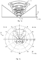
- Figs 3a and 3b show the field distribution 36 ( Fig 3a ) and far field 101 ( Fig 3b ) of a radar wave guiding arrangement 31 according to an example.
- Fig 3a schematically illustrates a radar wave guiding arrangement 31 where a dielectric insert 35 may be placed in a horn-shaped housing 38 such that at least one channel 34 is formed.
- the radar wave guiding arrangement 31 for a vehicle radar system comprises a horn-shaped housing 38.
- the housing 38 comprises first walls 32.
- the housing thereby encloses a cavity.
- the radar wave guiding arrangement 31 further comprises a dielectric insert 35.
- the dielectric 35 insert comprises second walls 33.
- the dielectric insert 35 is positioned inside the cavity. Hence the dielectric insert 35 is at least partly enclosed by the housing 38.
- the first walls 32 of the housing 38 and the second walls 33 of the dielectric insert 35 form at least one waveguide channel 34.
- the waveguide channel 34 has a width d.
- the waveguide channel 34 is provided for guiding radar waves through the horn-shaped housing 38.
- the dielectric insert 35 and the at least one waveguide channel 34 have different wave distribution characteristics.
- the disclosed radar wave guiding arrangement 31 may thus comprise a horn with a dielectric cone and an air (or other gas) filled waveguide channel 34 located between the cone (as formed by the dielectric insert 35) and the horn wall (as formed by the housing 38), where the air filled channel serves as a leaky waveguide.
- Fig 3b the far field of the electric field component perpendicular to the drawing plane (the xz-plane) of Fig 3a are shown.
- the width (taken in the x-axis direction) is larger than the length (taken in the z-axis direction) of the disclosed radar wave guiding arrangement 31. This yields a compact design of the radar wave guiding arrangement 31.
- the power in the waveguide channel 34 fades along the direction of propagation (i.e., the z-axis) which is caused by the power transfer into the cone shaped dielectric insert 35 where a wave of a plane phase front perpendicular to the horn axis (i.e., the z-axis) is generated.
- ⁇ ⁇ ⁇ H cos ⁇ ⁇
- epsilon ( ⁇ ) is the dielectric constant
- lambda ( ⁇ ) is the free space wavelength
- theta ( ⁇ ) is the angle of the channel axis to the horn axis (see, Fig 3a )
- the radar wave guiding arrangement 31 of Figs 3a and 3b is symmetric respect to the yz-plane, thus providing a symmetrical radiation.
- the different expressions comprising cosine-terms correspond to the right (H 1 ) and left (H 2 ) channel, respectively. Both channels may differ in size and/or slope angle.
- the gaps, or channels are asymmetrical to yield an asymmetrical radiation.
- the radar wave guiding arrangement comprises at least two asymmetrical channels. Such a radar wave guiding arrangement 41 is illustrated in Fig 4 .
- the waveguide channel 34 need not be linear. It may be curved; however the width has to be adjusted to satisfy the above equations.
- the material filling the waveguide channel 34 need not be air. It may be any other gas, liquid or solid with any dielectric constant epsilon.
- the waveguide channel 34 is gas-filled.
- the proper phase distribution in the cone i.e., in the dielectric insert 35
- the required transverse amplitude distribution has to be achieved. Quasi Gaussian or raised cosine distributions typically are desired.
- One advantage of the disclosed radar wave guiding arrangement 31, 41 is that for constant relative leakage of power from the waveguide channel 34 to the cone (i.e., in the dielectric insert 35) a maximum in the center and decay at the sides is inherently achieved.
- a fine tailoring of the transverse amplitude distribution takes advantage of the fact that the relative power leakage depends on the angle theta.
- a nonlinear channel can tailor the transverse field distribution.
- power leakage geometric obstacles can be introduced.
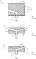
- Such a radar wave guiding arrangement 51 is illustrated in Fig 5 .
- the cone i.e., in the dielectric insert 35
- the second walls at least partly are covered with metallic sheets 40.
- the space between the sheets 40 is smaller than half of the wavelength for the depicted polarization of the electric field component these sheets 40 act as cut-off guides.
- grooves 39 at the cone (i.e., at the second walls 33 of the dielectric insert 35) or the horn (i.e., at the first walls 32 of the housing 38) can be provided. To have an influence their spacing should be about half the wavelength.
- the radar wave guiding arrangement comprises only one waveguide channel.
- Such a radar wave guiding arrangement 61 is illustrated in Fig 6 .
- the radar wave guiding arrangement 31, 41, 51, 61 comprises a radome 42.
- the dielectric insert 35 may be part of the radome 42.
- the dielectric insert 35 and the radome 42 may be provided as an integral structure.
- the cone i.e., the dielectric insert 35
- the horn i.e., to the first walls of the housing 32
- the radar wave guiding arrangement 31, 41, 51, 61 may further comprise a radar wave generator 37.
- the radome 42 and the radar wave generator 37 are positioned at opposite ends of the horn-shaped housing 38.
- a front side 43 of the radome 42 facing away from the radar wave generator 37 may be flat or smoothly curved.
- the components of the radar wave guiding arrangement 31, 41, 51, 61 thus are a cone-shaped metal horn which is mounted to a radar frequency wave-creating power source (generator) at one end and to a radome 42 at the other end.
- a dielectric insert 35 is mounted to, or integrated with, the radome 42.
- due to the change of wave impedance caused by the change of dielectric constant of the radome 42 may lead to an undesired reflection.
- this undesired reflection is minimized by choosing the thickness of the radome 42 such that the reflection at the inner radome 42 surface cancels with the reflection of the outer radome 42 surface.
- the thickness of the radome 42 may be chosen to be multiples of half the wavelength. For the disclosed radar wave guiding arrangement the situation is different. Inherently, due to the conical shape of the dielectric insert 35 the thickness of the radome 42 can generally not be chosen to be half the wavelength. Also a certain reflection at the inner surface is desired, otherwise the waveguide channel 34 would not act as such. That however means that the reflection at the inner and outer surfaces must be treated separately.
- the reflection can be adjusted by means of either a thin layer of dielectric material with a dielectric constant being the square root of the product of the dielectric constants of the waveguide channel 34 and the dielectric insert 35, or by providing conical grooves which do not require the need of a second material.
- the second walls 33 comprise grooves.
- the grooves may be conical shaped.
- the grooves may be triangular shaped.
- the housing 38 In the lateral direction (i.e., along the z-axis) the housing 38 may be narrow. At the end of the housing 38, but still inside the material, a reflection may occur.
- the remaining part of the radome 42 may therefore be chosen of a thickness such that the reflection at the housing end and at the outer surface cancel out.
- Such a radar wave guiding arrangement 71 is illustrated in Fig 7 , where the first location 72 of the reflection and the second location 73 of the reflection have been identified.
- the radome 42 and the dielectric insert 35 may be made from different materials. Fixation tabs or the like may be used to fixate the position of the dielectric insert 35 in relation to the housing 38.
- the radar wave guiding arrangement 31, 41, 51, 61, 71 further comprises fixation tabs arranged to fixate the position of the dielectric insert 35 in relation to the horn-shaped housing 38.
- Fig 8 illustrates the cross section (i.e., in the xy-plane) of a radar wave guiding arrangement 81.
- the radar wave guiding arrangement 31, 41, 51, 61, 71, 81 may be used for any frequency radar application but preferably for 77 GHz radar applications.
- the radar wave generator 34 is arranged to generate a 77 GHz automotive radar detection signal.
- An automotive vehicle may comprise a radar wave guiding arrangement 31, 41, 51, 61, 71, 81 according to any of the above disclosed examples.
- Fig 9 illustrates an automotive vehicle 91 comprising a radar wave guiding arrangement 31, 41, 51, 61, 71, 81.
- the radar wave guiding arrangement 31, 41, 51, 61, 71, 81 may thus be part used for, or as an integral part of, a vehicle radar system.
- a radar wave guiding arrangement 31, 41, 51, 61, 71, 81 for a vehicle radar system comprising a radar wave generator 37, a horn-shaped housing 38 with walls 32 forming a cavity and an dielectric insert 35 positioned inside the cavity, wherein the walls 32 and the dielectric insert 35 form at least one waveguide channel 34 for guiding generated radar waves, and where the dielectric insert 35 and the at least one waveguide channel 34 have different wave distribution characteristics.
Landscapes
- Engineering & Computer Science (AREA)
- Remote Sensing (AREA)
- Radar, Positioning & Navigation (AREA)
- Physics & Mathematics (AREA)
- Electromagnetism (AREA)
- Computer Networks & Wireless Communication (AREA)
- General Physics & Mathematics (AREA)
- Waveguide Aerials (AREA)
- Radar Systems Or Details Thereof (AREA)
Claims (14)
- Radarwellenleiteranordnung (31, 41, 51, 61, 71, 81) für ein Fahrzeugradarsystem, umfassend:ein hornförmiges Gehäuse (38), wobei das Gehäuse erste Wände (32) umfasst, die einen Hohlraum umschließen; undeinen dielektrischen Einsatz (35), wobei der dielektrische Einsatz zweite Wände (33) umfasst und im Inneren des Hohlraums angeordnet ist;wobei die ersten Wände und die zweiten Wände mindestens einen Wellenleiterkanal (34) zum Leiten von Radarwellen durch das hornförmige Gehäuse bilden, und wobei der Einsatz und der mindestens eine Wellenleiterkanal unterschiedliche Wellenverteilungseigenschaften aufweisen,wobei die Radarwellenleiteranordnung eine Breite und eine Länge aufweist und wobei die Breite größer als die Länge ist, wobei sich die Länge entlang einer Längsachse der Anordnung erstreckt, während sich die Breite entlang einer Querschnittsachse der Anordnung erstreckt,wobei die zweiten Wände zumindest teilweise mit Metallblechen (40) bedeckt sind und der Abstand zwischen den Metallblechen (40) kleiner als die Hälfte der Wellenlänge der Radarwellen des Radarsystems ist, sodass die Metallbleche (40) als Sperrleiter fungieren.
- Radarwellenleiteranordnung nach Anspruch 1, die ferner ein Radom (42) umfasst, und wobei der dielektrische Einsatz Teil des Radoms ist.
- Radarwellenleiteranordnung nach Anspruch 1 oder 2, die ferner einen Radarwellengenerator (37) umfasst.
- Radarwellenleiteranordnung nach Anspruch 2 und 3, wobei das Radom und der Radarwellengenerator an gegenüberliegenden Enden des hornförmigen Gehäuses angeordnet sind.
- Radarwellenleiteranordnung nach Anspruch 4, wobei eine dem Radarwellengenerator abgewandte Vorderseite (43) des Radoms flach oder leicht gekrümmt ist.
- Radarwellenleiteranordnung nach Anspruch 3, 4 oder 5, wobei der Radarwellengenerator dafür ausgelegt ist, ein Kraftfahrzeug-Radarerfassungssignal mit 77 GHz zu erzeugen.
- Radarwellenleiteranordnung nach einem der vorhergehenden Ansprüche, wobei mindestens die ersten Wände und/oder die zweiten Wände Rillen (39) aufweisen.
- Radarwellenleiteranordnung nach Anspruch 7, wobei die Rillen kegel- oder dreieckförmig sind.
- Radarwellenleiteranordnung nach einem der vorhergehenden Ansprüche, die ferner Fixierungslaschen umfasst, die dafür ausgelegt sind, die Position des dielektrischen Einsatzes in Bezug auf das hornförmige Gehäuse zu fixieren.
- Radarwellenleiteranordnung nach einem der vorhergehenden Ansprüche, die mindestens zwei asymmetrische Kanäle umfasst.
- Radarwellenleiteranordnung nach einem der Ansprüche 1 bis 9, die nur einen Wellenleiterkanal umfasst.
- Radarwellenleiteranordnung nach einem der vorhergehenden Ansprüche, wobei die Anordnung einen kreissymmetrischen Querschnitt aufweist.
- Radarwellenleiteranordnung nach einem der vorhergehenden Ansprüche, wobei der Wellenleiterkanal mit Gas gefüllt ist.
- Kraftfahrzeug (91), umfassend eine Radarwellenleitungsanordnung nach einem der vorhergehenden Ansprüche.
Priority Applications (1)
| Application Number | Priority Date | Filing Date | Title |
|---|---|---|---|
| EP13189519.5A EP2863475B1 (de) | 2013-10-21 | 2013-10-21 | Radarwellenleiteranordnung |
Applications Claiming Priority (1)
| Application Number | Priority Date | Filing Date | Title |
|---|---|---|---|
| EP13189519.5A EP2863475B1 (de) | 2013-10-21 | 2013-10-21 | Radarwellenleiteranordnung |
Publications (2)
| Publication Number | Publication Date |
|---|---|
| EP2863475A1 EP2863475A1 (de) | 2015-04-22 |
| EP2863475B1 true EP2863475B1 (de) | 2020-03-25 |
Family
ID=49385168
Family Applications (1)
| Application Number | Title | Priority Date | Filing Date |
|---|---|---|---|
| EP13189519.5A Active EP2863475B1 (de) | 2013-10-21 | 2013-10-21 | Radarwellenleiteranordnung |
Country Status (1)
| Country | Link |
|---|---|
| EP (1) | EP2863475B1 (de) |
Family Cites Families (2)
| Publication number | Priority date | Publication date | Assignee | Title |
|---|---|---|---|---|
| EP1139489A1 (de) * | 2000-03-31 | 2001-10-04 | Alps Electric Co., Ltd. | Primärstrahler mit verbessertem Empfangswirkungsgrad durch Reduzierung von Nebenkeulen |
| EP2469654B1 (de) | 2010-12-21 | 2014-08-27 | Siemens Aktiengesellschaft | Hornantenne für eine Radarvorrichtung |
-
2013
- 2013-10-21 EP EP13189519.5A patent/EP2863475B1/de active Active
Non-Patent Citations (1)
| Title |
|---|
| HONGMIN LEE ET AL: "A compact dielectric rod-loaded conical horn antenna for millimeter-wave apllications", MILLIMETER WAVES (GSMM), 2012 5TH GLOBAL SYMPOSIUM ON, IEEE, 27 May 2012 (2012-05-27), pages 182 - 185, XP032242969, ISBN: 978-1-4673-1302-5, DOI: 10.1109/GSMM.2012.6314031 * |
Also Published As
| Publication number | Publication date |
|---|---|
| EP2863475A1 (de) | 2015-04-22 |
Similar Documents
| Publication | Publication Date | Title |
|---|---|---|
| CN100492765C (zh) | 隙缝阵天线 | |
| US10714834B2 (en) | Broadband quad-ridge horn antennas | |
| US9136607B2 (en) | Antenna beam steering through waveguide mode mixing | |
| EP2375492A1 (de) | Antennenvorrichtung und Radargerät | |
| US20160218408A1 (en) | System for feeding high-frequency waves to deployment structure | |
| Genc et al. | Investigation of the characteristics of low-cost and lightweight horn array antennas with novel monolithic waveguide feeding networks | |
| US9293832B2 (en) | Broadband antenna feed array | |
| Choi et al. | Design of a dual-mode waveguide CP antenna with a symmetric beamwidth using short stub for low-orbit satellite TC&R | |
| US7852277B2 (en) | Circularly polarized horn antenna | |
| RU2124253C1 (ru) | Двухзеркальная осесимметричная антенна | |
| EP2863475B1 (de) | Radarwellenleiteranordnung | |
| US20120146866A1 (en) | Wireless communication antenna device | |
| US9882285B2 (en) | Dielectric hollow antenna | |
| Briqech et al. | 60 GHz circular patch-fed high gain transparent lens antenna | |
| JP2641944B2 (ja) | 進行波給電式同軸スロットアンテナ | |
| Liu et al. | Frequency-scanning dual-beam parallel-plate waveguide continuous transverse stub antenna array with sidelobe suppression | |
| Hirokawa et al. | Postwall waveguide slot array with cosecant radiation pattern and null filling for base station antennas in local multidistributed systems | |
| Lee et al. | Front‐to‐back ratio improvement of a short pyramidal horn antenna using metal strips/rods in LTE/cellular band | |
| Slimani et al. | Conception and optimization of a bidirectional ultra wide band planar array antennas for C-band weather radar applications | |
| Belous | Antennas and antenna devices for radar location and radio communication | |
| Armbrecht et al. | Dielectric travelling wave antennas incorporating cylindrical inserts with tapered cavities | |
| WO2006080130A1 (ja) | 導波管ホーンアンテナ、アンテナ装置、および、レーダ装置 | |
| Bouazza et al. | Novel 77 GHz SIW Antenna Solution Based on Stacked Waveguide Network for Automotive Radar System | |
| Bhanarkar et al. | Analysis of pyramidal horn antenna for J-band application | |
| RU2185696C1 (ru) | Уголковая антенна |
Legal Events
| Date | Code | Title | Description |
|---|---|---|---|
| PUAI | Public reference made under article 153(3) epc to a published international application that has entered the european phase |
Free format text: ORIGINAL CODE: 0009012 |
|
| 17P | Request for examination filed |
Effective date: 20131021 |
|
| AK | Designated contracting states |
Kind code of ref document: A1 Designated state(s): AL AT BE BG CH CY CZ DE DK EE ES FI FR GB GR HR HU IE IS IT LI LT LU LV MC MK MT NL NO PL PT RO RS SE SI SK SM TR |
|
| AX | Request for extension of the european patent |
Extension state: BA ME |
|
| R17P | Request for examination filed (corrected) |
Effective date: 20151022 |
|
| RBV | Designated contracting states (corrected) |
Designated state(s): AL AT BE BG CH CY CZ DE DK EE ES FI FR GB GR HR HU IE IS IT LI LT LU LV MC MK MT NL NO PL PT RO RS SE SI SK SM TR |
|
| STAA | Information on the status of an ep patent application or granted ep patent |
Free format text: STATUS: EXAMINATION IS IN PROGRESS |
|
| 17Q | First examination report despatched |
Effective date: 20180309 |
|
| RAP1 | Party data changed (applicant data changed or rights of an application transferred) |
Owner name: VEONEER SWEDEN AB |
|
| GRAP | Despatch of communication of intention to grant a patent |
Free format text: ORIGINAL CODE: EPIDOSNIGR1 |
|
| STAA | Information on the status of an ep patent application or granted ep patent |
Free format text: STATUS: GRANT OF PATENT IS INTENDED |
|
| INTG | Intention to grant announced |
Effective date: 20191015 |
|
| GRAS | Grant fee paid |
Free format text: ORIGINAL CODE: EPIDOSNIGR3 |
|
| GRAA | (expected) grant |
Free format text: ORIGINAL CODE: 0009210 |
|
| STAA | Information on the status of an ep patent application or granted ep patent |
Free format text: STATUS: THE PATENT HAS BEEN GRANTED |
|
| AK | Designated contracting states |
Kind code of ref document: B1 Designated state(s): AL AT BE BG CH CY CZ DE DK EE ES FI FR GB GR HR HU IE IS IT LI LT LU LV MC MK MT NL NO PL PT RO RS SE SI SK SM TR |
|
| REG | Reference to a national code |
Ref country code: GB Ref legal event code: FG4D |
|
| REG | Reference to a national code |
Ref country code: AT Ref legal event code: REF Ref document number: 1249651 Country of ref document: AT Kind code of ref document: T Effective date: 20200415 Ref country code: IE Ref legal event code: FG4D |
|
| REG | Reference to a national code |
Ref country code: DE Ref legal event code: R096 Ref document number: 602013067118 Country of ref document: DE |
|
| PG25 | Lapsed in a contracting state [announced via postgrant information from national office to epo] |
Ref country code: FI Free format text: LAPSE BECAUSE OF FAILURE TO SUBMIT A TRANSLATION OF THE DESCRIPTION OR TO PAY THE FEE WITHIN THE PRESCRIBED TIME-LIMIT Effective date: 20200325 Ref country code: NO Free format text: LAPSE BECAUSE OF FAILURE TO SUBMIT A TRANSLATION OF THE DESCRIPTION OR TO PAY THE FEE WITHIN THE PRESCRIBED TIME-LIMIT Effective date: 20200625 Ref country code: RS Free format text: LAPSE BECAUSE OF FAILURE TO SUBMIT A TRANSLATION OF THE DESCRIPTION OR TO PAY THE FEE WITHIN THE PRESCRIBED TIME-LIMIT Effective date: 20200325 |
|
| PG25 | Lapsed in a contracting state [announced via postgrant information from national office to epo] |
Ref country code: LV Free format text: LAPSE BECAUSE OF FAILURE TO SUBMIT A TRANSLATION OF THE DESCRIPTION OR TO PAY THE FEE WITHIN THE PRESCRIBED TIME-LIMIT Effective date: 20200325 Ref country code: SE Free format text: LAPSE BECAUSE OF FAILURE TO SUBMIT A TRANSLATION OF THE DESCRIPTION OR TO PAY THE FEE WITHIN THE PRESCRIBED TIME-LIMIT Effective date: 20200325 Ref country code: HR Free format text: LAPSE BECAUSE OF FAILURE TO SUBMIT A TRANSLATION OF THE DESCRIPTION OR TO PAY THE FEE WITHIN THE PRESCRIBED TIME-LIMIT Effective date: 20200325 Ref country code: GR Free format text: LAPSE BECAUSE OF FAILURE TO SUBMIT A TRANSLATION OF THE DESCRIPTION OR TO PAY THE FEE WITHIN THE PRESCRIBED TIME-LIMIT Effective date: 20200626 Ref country code: BG Free format text: LAPSE BECAUSE OF FAILURE TO SUBMIT A TRANSLATION OF THE DESCRIPTION OR TO PAY THE FEE WITHIN THE PRESCRIBED TIME-LIMIT Effective date: 20200625 |
|
| REG | Reference to a national code |
Ref country code: NL Ref legal event code: MP Effective date: 20200325 |
|
| REG | Reference to a national code |
Ref country code: LT Ref legal event code: MG4D |
|
| PG25 | Lapsed in a contracting state [announced via postgrant information from national office to epo] |
Ref country code: NL Free format text: LAPSE BECAUSE OF FAILURE TO SUBMIT A TRANSLATION OF THE DESCRIPTION OR TO PAY THE FEE WITHIN THE PRESCRIBED TIME-LIMIT Effective date: 20200325 |
|
| PG25 | Lapsed in a contracting state [announced via postgrant information from national office to epo] |
Ref country code: SM Free format text: LAPSE BECAUSE OF FAILURE TO SUBMIT A TRANSLATION OF THE DESCRIPTION OR TO PAY THE FEE WITHIN THE PRESCRIBED TIME-LIMIT Effective date: 20200325 Ref country code: LT Free format text: LAPSE BECAUSE OF FAILURE TO SUBMIT A TRANSLATION OF THE DESCRIPTION OR TO PAY THE FEE WITHIN THE PRESCRIBED TIME-LIMIT Effective date: 20200325 Ref country code: EE Free format text: LAPSE BECAUSE OF FAILURE TO SUBMIT A TRANSLATION OF THE DESCRIPTION OR TO PAY THE FEE WITHIN THE PRESCRIBED TIME-LIMIT Effective date: 20200325 Ref country code: PT Free format text: LAPSE BECAUSE OF FAILURE TO SUBMIT A TRANSLATION OF THE DESCRIPTION OR TO PAY THE FEE WITHIN THE PRESCRIBED TIME-LIMIT Effective date: 20200818 Ref country code: CZ Free format text: LAPSE BECAUSE OF FAILURE TO SUBMIT A TRANSLATION OF THE DESCRIPTION OR TO PAY THE FEE WITHIN THE PRESCRIBED TIME-LIMIT Effective date: 20200325 Ref country code: RO Free format text: LAPSE BECAUSE OF FAILURE TO SUBMIT A TRANSLATION OF THE DESCRIPTION OR TO PAY THE FEE WITHIN THE PRESCRIBED TIME-LIMIT Effective date: 20200325 Ref country code: IS Free format text: LAPSE BECAUSE OF FAILURE TO SUBMIT A TRANSLATION OF THE DESCRIPTION OR TO PAY THE FEE WITHIN THE PRESCRIBED TIME-LIMIT Effective date: 20200725 Ref country code: SK Free format text: LAPSE BECAUSE OF FAILURE TO SUBMIT A TRANSLATION OF THE DESCRIPTION OR TO PAY THE FEE WITHIN THE PRESCRIBED TIME-LIMIT Effective date: 20200325 |
|
| REG | Reference to a national code |
Ref country code: AT Ref legal event code: MK05 Ref document number: 1249651 Country of ref document: AT Kind code of ref document: T Effective date: 20200325 |
|
| REG | Reference to a national code |
Ref country code: DE Ref legal event code: R097 Ref document number: 602013067118 Country of ref document: DE |
|
| PG25 | Lapsed in a contracting state [announced via postgrant information from national office to epo] |
Ref country code: ES Free format text: LAPSE BECAUSE OF FAILURE TO SUBMIT A TRANSLATION OF THE DESCRIPTION OR TO PAY THE FEE WITHIN THE PRESCRIBED TIME-LIMIT Effective date: 20200325 Ref country code: AT Free format text: LAPSE BECAUSE OF FAILURE TO SUBMIT A TRANSLATION OF THE DESCRIPTION OR TO PAY THE FEE WITHIN THE PRESCRIBED TIME-LIMIT Effective date: 20200325 Ref country code: IT Free format text: LAPSE BECAUSE OF FAILURE TO SUBMIT A TRANSLATION OF THE DESCRIPTION OR TO PAY THE FEE WITHIN THE PRESCRIBED TIME-LIMIT Effective date: 20200325 Ref country code: DK Free format text: LAPSE BECAUSE OF FAILURE TO SUBMIT A TRANSLATION OF THE DESCRIPTION OR TO PAY THE FEE WITHIN THE PRESCRIBED TIME-LIMIT Effective date: 20200325 |
|
| PGFP | Annual fee paid to national office [announced via postgrant information from national office to epo] |
Ref country code: FR Payment date: 20201028 Year of fee payment: 8 |
|
| PLBE | No opposition filed within time limit |
Free format text: ORIGINAL CODE: 0009261 |
|
| STAA | Information on the status of an ep patent application or granted ep patent |
Free format text: STATUS: NO OPPOSITION FILED WITHIN TIME LIMIT |
|
| PG25 | Lapsed in a contracting state [announced via postgrant information from national office to epo] |
Ref country code: PL Free format text: LAPSE BECAUSE OF FAILURE TO SUBMIT A TRANSLATION OF THE DESCRIPTION OR TO PAY THE FEE WITHIN THE PRESCRIBED TIME-LIMIT Effective date: 20200325 |
|
| 26N | No opposition filed |
Effective date: 20210112 |
|
| PG25 | Lapsed in a contracting state [announced via postgrant information from national office to epo] |
Ref country code: SI Free format text: LAPSE BECAUSE OF FAILURE TO SUBMIT A TRANSLATION OF THE DESCRIPTION OR TO PAY THE FEE WITHIN THE PRESCRIBED TIME-LIMIT Effective date: 20200325 |
|
| REG | Reference to a national code |
Ref country code: CH Ref legal event code: PL |
|
| GBPC | Gb: european patent ceased through non-payment of renewal fee |
Effective date: 20201021 |
|
| PG25 | Lapsed in a contracting state [announced via postgrant information from national office to epo] |
Ref country code: LU Free format text: LAPSE BECAUSE OF NON-PAYMENT OF DUE FEES Effective date: 20201021 Ref country code: MC Free format text: LAPSE BECAUSE OF FAILURE TO SUBMIT A TRANSLATION OF THE DESCRIPTION OR TO PAY THE FEE WITHIN THE PRESCRIBED TIME-LIMIT Effective date: 20200325 |
|
| REG | Reference to a national code |
Ref country code: BE Ref legal event code: MM Effective date: 20201031 |
|
| PG25 | Lapsed in a contracting state [announced via postgrant information from national office to epo] |
Ref country code: BE Free format text: LAPSE BECAUSE OF NON-PAYMENT OF DUE FEES Effective date: 20201031 Ref country code: CH Free format text: LAPSE BECAUSE OF NON-PAYMENT OF DUE FEES Effective date: 20201031 Ref country code: GB Free format text: LAPSE BECAUSE OF NON-PAYMENT OF DUE FEES Effective date: 20201021 Ref country code: LI Free format text: LAPSE BECAUSE OF NON-PAYMENT OF DUE FEES Effective date: 20201031 |
|
| PG25 | Lapsed in a contracting state [announced via postgrant information from national office to epo] |
Ref country code: IE Free format text: LAPSE BECAUSE OF NON-PAYMENT OF DUE FEES Effective date: 20201021 |
|
| PG25 | Lapsed in a contracting state [announced via postgrant information from national office to epo] |
Ref country code: TR Free format text: LAPSE BECAUSE OF FAILURE TO SUBMIT A TRANSLATION OF THE DESCRIPTION OR TO PAY THE FEE WITHIN THE PRESCRIBED TIME-LIMIT Effective date: 20200325 Ref country code: MT Free format text: LAPSE BECAUSE OF FAILURE TO SUBMIT A TRANSLATION OF THE DESCRIPTION OR TO PAY THE FEE WITHIN THE PRESCRIBED TIME-LIMIT Effective date: 20200325 Ref country code: CY Free format text: LAPSE BECAUSE OF FAILURE TO SUBMIT A TRANSLATION OF THE DESCRIPTION OR TO PAY THE FEE WITHIN THE PRESCRIBED TIME-LIMIT Effective date: 20200325 |
|
| PG25 | Lapsed in a contracting state [announced via postgrant information from national office to epo] |
Ref country code: MK Free format text: LAPSE BECAUSE OF FAILURE TO SUBMIT A TRANSLATION OF THE DESCRIPTION OR TO PAY THE FEE WITHIN THE PRESCRIBED TIME-LIMIT Effective date: 20200325 Ref country code: AL Free format text: LAPSE BECAUSE OF FAILURE TO SUBMIT A TRANSLATION OF THE DESCRIPTION OR TO PAY THE FEE WITHIN THE PRESCRIBED TIME-LIMIT Effective date: 20200325 |
|
| PG25 | Lapsed in a contracting state [announced via postgrant information from national office to epo] |
Ref country code: FR Free format text: LAPSE BECAUSE OF NON-PAYMENT OF DUE FEES Effective date: 20211031 |
|
| REG | Reference to a national code |
Ref country code: DE Ref legal event code: R081 Ref document number: 602013067118 Country of ref document: DE Owner name: ARRIVER SOFTWARE AB, SE Free format text: FORMER OWNER: VEONEER SWEDEN AB, VARGARDA, SE Ref country code: DE Ref legal event code: R081 Ref document number: 602013067118 Country of ref document: DE Owner name: QUALCOMM AUTO LTD., GB Free format text: FORMER OWNER: VEONEER SWEDEN AB, VARGARDA, SE |
|
| REG | Reference to a national code |
Ref country code: DE Ref legal event code: R081 Ref document number: 602013067118 Country of ref document: DE Owner name: QUALCOMM AUTO LTD., GB Free format text: FORMER OWNER: ARRIVER SOFTWARE AB, LINKOEPING, SE |
|
| PGFP | Annual fee paid to national office [announced via postgrant information from national office to epo] |
Ref country code: DE Payment date: 20250912 Year of fee payment: 13 |