EP2863392A2 - Noise reduction in multi-microphone systems - Google Patents
Noise reduction in multi-microphone systems Download PDFInfo
- Publication number
- EP2863392A2 EP2863392A2 EP14188582.2A EP14188582A EP2863392A2 EP 2863392 A2 EP2863392 A2 EP 2863392A2 EP 14188582 A EP14188582 A EP 14188582A EP 2863392 A2 EP2863392 A2 EP 2863392A2
- Authority
- EP
- European Patent Office
- Prior art keywords
- audio signal
- microphone
- audio signals
- signals
- audio
- Prior art date
- Legal status (The legal status is an assumption and is not a legal conclusion. Google has not performed a legal analysis and makes no representation as to the accuracy of the status listed.)
- Granted
Links
Images




Classifications
-
- H—ELECTRICITY
- H04—ELECTRIC COMMUNICATION TECHNIQUE
- H04R—LOUDSPEAKERS, MICROPHONES, GRAMOPHONE PICK-UPS OR LIKE ACOUSTIC ELECTROMECHANICAL TRANSDUCERS; ELECTRIC HEARING AIDS; PUBLIC ADDRESS SYSTEMS
- H04R3/00—Circuits for transducers
- H04R3/002—Damping circuit arrangements for transducers, e.g. motional feedback circuits
-
- G—PHYSICS
- G10—MUSICAL INSTRUMENTS; ACOUSTICS
- G10L—SPEECH ANALYSIS TECHNIQUES OR SPEECH SYNTHESIS; SPEECH RECOGNITION; SPEECH OR VOICE PROCESSING TECHNIQUES; SPEECH OR AUDIO CODING OR DECODING
- G10L19/00—Speech or audio signals analysis-synthesis techniques for redundancy reduction, e.g. in vocoders; Coding or decoding of speech or audio signals, using source filter models or psychoacoustic analysis
- G10L19/008—Multichannel audio signal coding or decoding using interchannel correlation to reduce redundancy, e.g. joint-stereo, intensity-coding or matrixing
-
- G—PHYSICS
- G10—MUSICAL INSTRUMENTS; ACOUSTICS
- G10L—SPEECH ANALYSIS TECHNIQUES OR SPEECH SYNTHESIS; SPEECH RECOGNITION; SPEECH OR VOICE PROCESSING TECHNIQUES; SPEECH OR AUDIO CODING OR DECODING
- G10L21/00—Speech or voice signal processing techniques to produce another audible or non-audible signal, e.g. visual or tactile, in order to modify its quality or its intelligibility
- G10L21/02—Speech enhancement, e.g. noise reduction or echo cancellation
- G10L21/0208—Noise filtering
-
- H—ELECTRICITY
- H04—ELECTRIC COMMUNICATION TECHNIQUE
- H04R—LOUDSPEAKERS, MICROPHONES, GRAMOPHONE PICK-UPS OR LIKE ACOUSTIC ELECTROMECHANICAL TRANSDUCERS; ELECTRIC HEARING AIDS; PUBLIC ADDRESS SYSTEMS
- H04R1/00—Details of transducers, loudspeakers or microphones
- H04R1/08—Mouthpieces; Microphones; Attachments therefor
-
- H—ELECTRICITY
- H04—ELECTRIC COMMUNICATION TECHNIQUE
- H04R—LOUDSPEAKERS, MICROPHONES, GRAMOPHONE PICK-UPS OR LIKE ACOUSTIC ELECTROMECHANICAL TRANSDUCERS; ELECTRIC HEARING AIDS; PUBLIC ADDRESS SYSTEMS
- H04R3/00—Circuits for transducers
- H04R3/005—Circuits for transducers for combining the signals of two or more microphones
-
- G—PHYSICS
- G10—MUSICAL INSTRUMENTS; ACOUSTICS
- G10L—SPEECH ANALYSIS TECHNIQUES OR SPEECH SYNTHESIS; SPEECH RECOGNITION; SPEECH OR VOICE PROCESSING TECHNIQUES; SPEECH OR AUDIO CODING OR DECODING
- G10L21/00—Speech or voice signal processing techniques to produce another audible or non-audible signal, e.g. visual or tactile, in order to modify its quality or its intelligibility
- G10L21/02—Speech enhancement, e.g. noise reduction or echo cancellation
- G10L21/0208—Noise filtering
- G10L21/0216—Noise filtering characterised by the method used for estimating noise
- G10L2021/02161—Number of inputs available containing the signal or the noise to be suppressed
- G10L2021/02166—Microphone arrays; Beamforming
-
- H—ELECTRICITY
- H04—ELECTRIC COMMUNICATION TECHNIQUE
- H04R—LOUDSPEAKERS, MICROPHONES, GRAMOPHONE PICK-UPS OR LIKE ACOUSTIC ELECTROMECHANICAL TRANSDUCERS; ELECTRIC HEARING AIDS; PUBLIC ADDRESS SYSTEMS
- H04R2410/00—Microphones
- H04R2410/01—Noise reduction using microphones having different directional characteristics
Definitions
- the present application relates to apparatus and methods for the implementation of noise reduction or audio enhancement in multi-microphone systems and specifically but not only implementation of noise reduction or audio enhancement in multi-microphone systems within mobile apparatus.
- Audio recording systems can make use of more than one microphone to pick-up and record audio in the surrounding environment.
- multi-microphone systems permit the implementation of digital signal processing such as speech enhancement to be applied to the microphone outputs.
- digital signal processing such as speech enhancement
- the intention in speech enhancement is to use mathematical methods to improve the quality of speech, presented as digital signals.
- One speech enhancement implementation is concerned with uplink processing the audio signals from three inputs or microphones.
- a method comprising: receiving at least three microphone audio signals, the at least three microphone audio signals comprising at least two near microphone audio signals generated by at least two near microphones located near to an desired audio source and at least one far microphone audio signal generated by a far microphone located further from the desired audio source than the at least two near microphones; generating a first processed audio signal based on a first selection from the at least three microphone audio signals, the first selection being from the near microphone audio signals; generating at least one further processed audio signal based on at least one further selection from the at least three microphone audio signals, the at least one further selection from the at least three microphone audio signals, the second selection being from all of the microphone signals; determining from the first processed audio signal and the at least one further processed audio signal the audio signal with greater noise suppression.
- the greater noise suppression may comprise improved noise suppression.
- Receiving at least three microphone audio signals may comprise: receiving a first microphone audio signal from a first near microphone located substantially at a front of an apparatus; receiving a second microphone audio signal from a second near microphone located substantially at a rear of the apparatus; and receiving a third microphone audio signal from a far microphone located substantially at the opposite end from the first and second microphones.
- Generating a first processed audio signal based on a first selection from the at least three microphone audio signals may comprise generating a first processed audio signal based on a main beam audio signal based on the first and second microphone audio signals and an anti-beam audio signal based on the first and second microphone audio signals.
- Generating at least one further processed audio signal based on at least one further selection from the at least three microphone audio signals comprises generating a further processed audio signal based on a main beam audio signal based on the first and second microphone audio signals and the third microphone audio signal.
- the method may further comprise: generating a main beam audio signal by: applying a first finite impulse response filter to the first audio signal; applying a second finite impulse response filter to the second audio signal; and combining the output of the first impulse response filter and the second finite response filter to generate the main beam audio signal; and generating an anti-beam audio signal by: applying a third finite impulse response filter to the first audio signal; applying a fourth finite impulse response filter to the second audio signal; and combining the output of the third impulse response filter and the fourth finite response filter to generate the anti-beam audio signal.
- Generating a further processed audio signal based on a main beam audio signal based on the first and second microphone audio signals and the third microphone audio signal may comprise filtering the main beam audio signal based on the third microphone audio signal.
- Generating a first processed audio signal based on a main beam audio signal based on the first and second microphone audio signals and an anti-beam audio signal based on the first and second microphone audio signals may comprise filtering the main beam audio signal based on the anti-beam audio signal.
- Generating a first processed audio signal based on a first selection from the at least three microphone audio signals may comprise: selecting as a first processing input at least one of: one of the at least three microphone audio signals; and a beamformed audio signal based on at least two of the at least three microphone audio signals, the selections being from the near microphone audio signals; selecting as a second processing input at least one of: one of the at least three microphone audio signals; and a beamformed audio signal based on the at least three microphone audio signals, the selections being from the near microphone audio signals; filtering the first processing input based on the second processing input to generate the first processed audio signal.
- Generating at least one further processed audio signal based on at least one further selection from the at least three microphone audio signals may comprise: selecting as a first processing input at least one of: one of the at least three microphone audio signals; and a beamformed audio signal based on at least two of the at least three microphone audio signals, the selections being from all of the microphone signals; selecting as a second processing input at least one of: one of the at least three microphone audio signals; and a beamformed audio signal based on at least two of the at least three microphone audio signals, the selections being from all of the microphone signals; filtering the first processing input based on the second processing input to generate the at least one further processed audio signal.
- Filtering the first processing input based on the second processing input to generate the at least one further processed audio signal may comprise noise suppression filtering the first processing input based on the second processing input.
- the method may further comprise beamforming at least two of the at least three microphone audio signals to generate a beamformed audio signal.
- Beamforming at least two of the at least three microphone audio signals to generate a beamformed audio signal may comprise: applying a first finite impulse response filter to a first of the at least two of the at least three microphone audio signals; applying a second finite impulse response filter to a second of the at least two of the at least three microphone audio signals; and combining the output of the first impulse response filter and the second finite response filter to generate the beamformed audio signal.
- the method may further comprise single channel noise suppressing the audio signal with greater noise suppression, wherein single channel noise suppressing comprises: generating an indicator showing whether a period of the audio signal comprises a lack of speech components or is significantly noise; estimating and updating a background noise from the audio signal when the indicator shows the period of the audio signal comprises a lack of speech components or is significantly noise; processing the audio signal based on the background noise estimate to generate a noise suppressed audio signal.
- Generating an indicator showing whether a period of the audio signal comprises a lack of speech components or is significantly noise may comprise: normalising a selection from the at least three microphone audio signals, wherein the selection comprises: beamformed audio signals of at least two of the at least three microphone audio signals; and microphone audio signals; filtering the normalised selections from the at least three microphone audio signals; comparing the filtered normalised selections to determine a power difference ratio; generating the indicator showing a period of the audio signal comprises a lack of speech components or is significantly noise where at least one comparison of filtered normalised selections has a power difference ratio greater than a determined threshold.
- Determining from the first processed audio signal and the at least one further processed audio signal the audio signal with greater noise suppression may comprise at least one of: determining from the first processed audio signal and the at least one further processed audio signal the audio signal with the highest signal level output; and determining from the first processed audio signal and the at least one further processed audio signal the audio signal with the highest power level output.
- an apparatus comprising at least one processor and at least one memory including computer code for one or more programs, the at least one memory and the computer code configured to with the at least one processor cause the apparatus to: receive at least three microphone audio signals, the at least three microphone audio signals comprising at least two near microphone audio signals generated by at least two near microphones located near to an desired audio source and at least one far microphone audio signal generated by a far microphone located further from the desired audio source than the at least two near microphones; generate a first processed audio signal based on a first selection from the at least three microphone audio signals, the first selection being from the near microphone audio signals; generate at least one further processed audio signal based on at least one further selection from the at least three microphone audio signals, the at least one further selection from the at least three microphone audio signals, the second selection being from all of the microphone signals; determine from the first processed audio signal and the at least one further processed audio signal the audio signal with greater noise suppression.
- Receiving at least three microphone audio signals may cause the apparatus to: receive a first microphone audio signal from a first near microphone located substantially at a front of an apparatus; receive a second microphone audio signal from a second near microphone located substantially at a rear of the apparatus; and receive a third microphone audio signal from a far microphone located substantially at the opposite end from the first and second microphones.
- Generating a first processed audio signal based on a first selection from the at least three microphone audio signals may cause the apparatus to generate a first processed audio signal based on a main beam audio signal based on the first and second microphone audio signals and an anti-beam audio signal based on the first and second microphone audio signals.
- Generating at least one further processed audio signal based on at least one further selection from the at least three microphone audio signals may cause the apparatus to generate a further processed audio signal based on a main beam audio signal based on the first and second microphone audio signals and the third microphone audio signal.
- the apparatus may be further caused to: generate a main beam audio signal by applying a first finite impulse response filter to the first audio signal; applying a second finite impulse response filter to the second audio signal; and combining the output of the first impulse response filter and the second finite response filter to generate the main beam audio signal; and generate an anti-beam audio signal by: applying a third finite impulse response filter to the first audio signal; applying a fourth finite impulse response filter to the second audio signal; and combining the output of the third impulse response filter and the fourth finite response filter to generate the anti-beam audio signal.
- Generating a further processed audio signal based on a main beam audio signal based on the first and second microphone audio signals and the third microphone audio signal may cause the apparatus to filter the main beam audio signal based on the third microphone audio signal.
- Generating a first processed audio signal based on a main beam audio signal based on the first and second microphone audio signals and an anti-beam audio signal based on the first and second microphone audio signals may cause the apparatus to filter the main beam audio signal based on the anti-beam audio signal.
- Generating a first processed audio signal based on a first selection from the at least three microphone audio signals may cause the apparatus to: select as a first processing input at least one of: one of the at least three microphone audio signals; and a beamformed audio signal based on at least two of the at least three microphone audio signals, the selections being from the near microphone audio signals; select as a second processing input at least one of: one of the at least three microphone audio signals; and a beamformed audio signal based on the at least three microphone audio signals, the selections being from the near microphone audio signals; filter the first processing input based on the second processing input to generate the first processed audio signal.
- Generating at least one further processed audio signal based on at least one further selection from the at least three microphone audio signals may cause the apparatus to: select as a first processing input at least one of: one of the at least three microphone audio signals; and a beamformed audio signal based on at least two of the at least three microphone audio signals, the selections being from all of the microphone signals; select as a second processing input at least one of: one of the at least three microphone audio signals; and a beamformed audio signal based on at least two of the at least three microphone audio signals, the selections being from all of the microphone signals; filter the first processing input based on the second processing input to generate the at least one further processed audio signal.
- Filtering the first processing input based on the second processing input to generate the at least one further processed audio signal may cause the apparatus to noise suppression filter the first processing input based on the second processing input.
- the apparatus may be caused to beamform at least two of the at least three microphone audio signals to generate a beamformed audio signal.
- Beamforming at least two of the at least three microphone audio signals to generate a beamformed audio signal may cause the apparatus to: apply a first finite impulse response filter to a first of the at least two of the at least three microphone audio signals; apply a second finite impulse response filter to a second of the at least two of the at least three microphone audio signals; and combine the output of the first impulse response filter and the second finite response filter to generate the beamformed audio signal.
- the apparatus may be caused to single channel noise suppress the audio signal with greater noise suppression, wherein single channel noise suppressing may cause the apparatus to: generate an indicator showing whether a period of the audio signal comprises a lack of speech components or is significantly noise; estimate and update a background noise from the audio signal when the indicator shows the period of the audio signal comprises a lack of speech components or is significantly noise; process the audio signal based on the background noise estimate to generate a noise suppressed audio signal.
- Generating an indicator showing whether a period of the audio signal comprises a lack of speech components or is significantly noise may cause the apparatus to: normalise a selection from the at least three microphone audio signals, wherein the selection comprises: beamformed audio signals of at least two of the at least three microphone audio signals; and microphone audio signals; filter the normalised selections from the at least three microphone audio signals; compare the filtered normalised selections to determine a power difference ratio; generate the indicator showing a period of the audio signal comprises a lack of speech components or is significantly noise where at least one comparison of filtered normalised selections has a power difference ratio greater than a determined threshold.
- Determining from the first processed audio signal and the at least one further processed audio signal the audio signal with greater noise suppression may cause the apparatus to perform at least one of: determine from the first processed audio signal and the at least one further processed audio signal the audio signal with the highest signal level output; and determine from the first processed audio signal and the at least one further processed audio signal the audio signal with the highest power level output.
- an apparatus comprising: an input configured to receive at least three microphone audio signals, the at least three microphone audio signals comprising at least two near microphone audio signals generated by at least two near microphones located near to an desired audio source and at least one far microphone audio signal generated by a far microphone located further from the desired audio source than the at least two near microphones; a first interference canceller module configured to generate a first processed audio signal based on a first selection from the at least three microphone audio signals, the first selection being from the near microphone audio signals; at least one further interference canceller module configured to generate at least one further processed audio signal based on at least one further selection from the at least three microphone audio signals, the at least one further selection from the at least three microphone audio signals, the second selection being from all of the microphone signals; a comparator configured to determine from the first processed audio signal and the at least one further processed audio signal the audio signal with greater noise suppression.
- the input may be configured to: receive a first microphone audio signal from a first near microphone located substantially at a front of an apparatus; receive a second microphone audio signal from a second near microphone located substantially at a rear of the apparatus; and receive a third microphone audio signal from a far microphone located substantially at the opposite end from the first and second microphones.
- the first interference canceller module may be configured to generate a first processed audio signal based on a main beam audio signal based on the first and second microphone audio signals and an anti-beam audio signal based on the first and second microphone audio signals.
- the at least one further interference canceller module may be configured to generate a further processed audio signal based on a main beam audio signal based on the first and second microphone audio signals and the third microphone audio signal.
- the apparatus may further comprise: a main beam beamformer configured to generate a main beam audio signal comprising a first finite impulse response filter configured to receive the first audio signal; a second finite impulse response filter configured to receive the second audio signal; and a combiner configured to combine the output of the first impulse response filter and the second finite response filter to generate the main beam audio signal; and an anti-beam beamformer configured to generate an anti-beam audio signal comprising: a third finite impulse response filter configured to receive the first audio signal; a fourth finite impulse response filter configured to receive the second audio signal; and a combiner configured to combine the output of the third impulse response filter and the fourth finite response filter to generate the anti-beam audio signal.
- a main beam beamformer configured to generate a main beam audio signal comprising a first finite impulse response filter configured to receive the first audio signal; a second finite impulse response filter configured to receive the second audio signal; and a combiner configured to combine the output of the third impulse response filter and the fourth finite response filter to generate the anti-
- the at least one further interference canceller module may comprise a filter configured to filter the main beam audio signal based on the third microphone audio signal.
- the first interference canceller module may comprise a filter configured to filter the main beam audio signal based on the anti-beam audio signal.
- the first interference canceller module may comprise: a selector configured to select as a first processing input at least one of: one of the at least three microphone audio signals; and a beamformed audio signal based on at least two of the at least three microphone audio signals, the selections being from the near microphone audio signals; a second selector configured to select as a second processing input at least one of: one of the at least three microphone audio signals; and a beamformed audio signal based on the at least three microphone audio signals, the selections being from the near microphone audio signals; a filter configured to filter the first processing input based on the second processing input to generate the first processed audio signal.
- the at least one further interference generator may comprise: a selector configured to select as a first processing input at least one of: one of the at least three microphone audio signals; and a beamformed audio signal based on at least two of the at least three microphone audio signals, the selections being from all of the microphone signals; a second selector configured to select as a second processing input at least one of: one of the at least three microphone audio signals; and a beamformed audio signal based on at least two of the at least three microphone audio signals, the selections being from all of the microphone signals; a filter configured to filter the first processing input based on the second processing input to generate the at least one further processed audio signal.
- the filter may be configured to noise suppression filter the first processing input based on the second processing input.
- the apparatus may comprise a beamformer configured to beamform at least two of the at least three microphone audio signals to generate a beamformed audio signal.
- the beamformer may comprise: a first finite impulse response filter configured to filter a first of the at least two of the at least three microphone audio signals; a second finite response filter configured to filter to a second of the at least two of the at least three microphone audio signals; and a combiner configured to combine the output of the first impulse response filter and the second finite response filter to generate the beamformed audio signal.
- the apparatus may comprise a single channel noise suppressor configured to noise suppress the audio signal with greater noise suppression
- the single channel noise suppressor may comprise: an input configured to receive an indicator showing whether a period of the audio signal comprises a lack of speech components or is significantly noise; an estimator configured to estimate and update a background noise from the audio signal when the indicator shows the period of the audio signal comprises a lack of speech components or is significantly noise; a filter configured to process the audio signal with greater noise suppression based on the background noise estimate to generate a noise suppressed audio signal.
- the apparatus may comprise a voice activity detector configured to generate an indicator showing whether a period of the audio signal comprises a lack of speech components or is significantly noise comprising: a normaliser configured to normalise a selection from the at least three microphone audio signals, wherein the selection comprises: beamformed audio signals of at least two of the at least three microphone audio signals; and microphone audio signals; a filter configured to filter the normalised selections from the at least three microphone audio signals; a comparator configured to compare the filtered normalised selections to determine a power difference ratio; an indicator generator configured to generate the indicator showing a period of the audio signal with greater noise suppression comprises a lack of speech components or is significantly noise where at least one comparison of filtered normalised selections has a power difference ratio greater than a determined threshold.
- a voice activity detector configured to generate an indicator showing whether a period of the audio signal comprises a lack of speech components or is significantly noise comprising: a normaliser configured to normalise a selection from the at least three microphone audio signals, wherein the selection comprises: beamformed audio signals of at least two
- the comparator configured to determine from the first processed audio signal and the at least one further processed audio signal the audio signal with greater noise suppression may be configured to perform at least one of: determine from the first processed audio signal and the at least one further processed audio signal the audio signal with the highest signal level output; and determine from the first processed audio signal and the at least one further processed audio signal the audio signal with the highest power level output.
- an apparatus comprising: means for receiving at least three microphone audio signals, the at least three microphone audio signals comprising at least two near microphone audio signals generated by at least two near microphones located near to an desired audio source and at least one far microphone audio signal generated by a far microphone located further from the desired audio source than the at least two near microphones; means for generating a first processed audio signal based on a first selection from the at least three microphone audio signals, the first selection being from the near microphone audio signals; means for generating at least one further processed audio signal based on at least one further selection from the at least three microphone audio signals, the at least one further selection from the at least three microphone audio signals, the second selection being from all of the microphone signals; means for determining from the first processed audio signal and the at least one further processed audio signal the audio signal with greater noise suppression.
- the means for receiving at least three microphone audio signals may comprise: means for receiving a first microphone audio signal from a first near microphone located substantially at a front of an apparatus; means for receiving a second microphone audio signal from a second near microphone located substantially at a rear of the apparatus; and means for receiving a third microphone audio signal from a far microphone located substantially at the opposite end from the first and second microphones.
- the means for generating a first processed audio signal based on a first selection from the at least three microphone audio signals may comprise means for generating a first processed audio signal based on a main beam audio signal based on the first and second microphone audio signals and an anti-beam audio signal based on the first and second microphone audio signals.
- the means for generating at least one further processed audio signal based on at least one further selection from the at least three microphone audio signals may comprise means for generating a further processed audio signal based on a main beam audio signal based on the first and second microphone audio signals and the third microphone audio signal.
- the means for generating a further processed audio signal based on a main beam audio signal based on the first and second microphone audio signals and the third microphone audio signal may comprise means for filtering the main beam audio signal based on the third microphone audio signal.
- the means for generating a first processed audio signal based on a main beam audio signal based on the first and second microphone audio signals and an anti-beam audio signal based on the first and second microphone audio signals may comprise means for filtering the main beam audio signal based on the anti-beam audio signal.
- the means for generating a first processed audio signal based on a first selection from the at least three microphone audio signals may comprise: means for selecting as a first processing input at least one of: one of the at least three microphone audio signals; and a beamformed audio signal based on at least two of the at least three microphone audio signals, the selections being from the near microphone audio signals; means for selecting as a second processing input at least one of: one of the at least three microphone audio signals; and a beamformed audio signal based on the at least three microphone audio signals, the selections being from the near microphone audio signals; means for filtering the first processing input based on the second processing input to generate the first processed audio signal.
- the means for generating at least one further processed audio signal based on at least one further selection from the at least three microphone audio signals may comprise: means for selecting as a first processing input at least one of: one of the at least three microphone audio signals; and a beamformed audio signal based on at least two of the at least three microphone audio signals, the selections being from all of the microphone signals; means for selecting as a second processing input at least one of: one of the at least three microphone audio signals; and a beamformed audio signal based on at least two of the at least three microphone audio signals, the selections being from all of the microphone signals; means for filtering the first processing input based on the second processing input to generate the at least one further processed audio signal.
- the means for filtering the first processing input based on the second processing input to generate the at least one further processed audio signal comprises noise suppression filtering the first processing input based on the second processing input.
- the apparatus may further comprise means for beamforming at least two of the at least three microphone audio signals to generate a beamformed audio signal.
- the means for beamforming at least two of the at least three microphone audio signals to generate a beamformed audio signal may comprise: means for applying a first finite impulse response filter to a first of the at least two of the at least three microphone audio signals; means for applying a second finite impulse response filter to a second of the at least two of the at least three microphone audio signals; and means for combining the output of the first impulse response filter and the second finite response filter to generate the beamformed audio signal.
- the apparatus may further comprise means for single channel noise suppressing the audio signal with greater noise suppression, wherein the means for single channel noise suppressing may comprise: means for generating an indicator showing whether a period of the audio signal comprises a lack of speech components or is significantly noise; means for estimating and updating a background noise from the audio signal when the indicator shows the period of the audio signal comprises a lack of speech components or is significantly noise; means for processing the audio signal based on the background noise estimate to generate a noise suppressed audio signal.
- the means for generating an indicator showing whether a period of the audio signal comprises a lack of speech components or is significantly noise may comprise: means for normalising a selection from the at least three microphone audio signals, wherein the selection comprises: beamformed audio signals of at least two of the at least three microphone audio signals; and microphone audio signals; means for filtering the normalised selections from the at least three microphone audio signals; means for comparing the filtered normalised selections to determine a power difference ratio; means for generating the indicator showing a period of the audio signal comprises a lack of speech components or is significantly noise where at least one comparison of filtered normalised selections has a power difference ratio greater than a determined threshold.
- the means for determining from the first processed audio signal and the at least one further processed audio signal the audio signal with greater noise suppression comprises at least one of: means for determining from the first processed audio signal and the at least one further processed audio signal the audio signal with the highest signal level output; and means for determining from the first processed audio signal and the at least one further processed audio signal the audio signal with the highest power level output.
- Embodiments of the present application aim to address problems associated with the state of the art.
- Some digital signal processing speech enhancement implementations use three microphone signals (from the available number of microphones on the apparatus or coupled to the apparatus). Two of the microphones or input signals originate from 'nearmics', (in other words microphones that are located close to each other such as at the bottom of the device) and a third microphone, 'farmic', located further away in the other end of the apparatus or device.
- FIG. 2 shows the apparatus with a first microphone (mic1) 101, a front 'nearmic', located towards the bottom of the apparatus and facing the display or front of the apparatus, a second microphone (mic2) 103, a rear 'nearmic', shown by the dashed oval and located towards the bottom of the apparatus and on the opposite face to the display (or otherwise on the rear of the apparatus) and a third microphone (mic3) 105, a 'farmic', located on the 'top' of the apparatus 10.
- a 3 microphone system configuration it would be understood that in some embodiments the system can comprise more than 3 microphones from which a suitable selection of 3 microphones can be made.
- two or more nearmics it is possible to form two directional beams from the audio signals generated from the microphones.
- These can for example as shown in Figure 5 be a 'mainbeam' 401 and 'antibeam' 403.
- the 'mainbeam' local speech is substantially passed while noise coming from opposite direction is significantly attenuated.
- the 'antibeam' local speech is substantially attenuated while noise from other directions is substantially passed. In such situations the level of ambient noise is almost the same in both beams.
- These beams can in some embodiments be used in further digital signal processing to further reduce remaining background noise from the main beam audio signal using an adaptive interference canceller (AIC) and spectral subtraction.
- AIC adaptive interference canceller
- the adaptive interference canceller (AIC) with two near microphone audio signals can perform a first method to further cancel noise from the main beam. Although with one nearmic audio signal and one farmic audio signal beamforming is not possible, AIC can be used with microphone signals directly. Furthermore noise can be further reduced using spectral subtraction.
- the first method using beam forming of the microphone audio signals to reduce noise is understood to provide efficient noise reductions, but it is sensitive to how the device is held.
- the second method using direct microphone audio signals is more orientation robust, but does not provide as efficient a noise reduction.
- a spatial voice activity detector (VAD) can be used to improve noise suppression compared to single channel case with no directional information available.
- Spatial VADs can for example be combined with other VADs in signal processing and the background noise estimate can be updated when the voice activity detector determines that the audio signal does not contain voiced components. In other words the background noise estimate can be updated when the VAD method flags noise.
- An example of non-spatial voice activity detection to improve noise suppression is shown in US patent number 8244528 .
- the spatial VAD output is typically the ratio between the determined or estimated main beam and the anti-beam powers.
- the spatial VAD output is typically the ratio between the input signals.
- the spatial VAD and AIC are both sensitive to the positioning of the apparatus or device.
- the adaptive interference canceller (AIC) or noise suppressor may consider it as noise and attenuate local speech. It is understood that the problem is more severe with beamforming audio signal methods but also exists with the direct microphone audio signal methods.
- the inventive concept as described in embodiments herein implements audio signal processing employing a third or further microphone(s) and addressing the problem of providing noise reduction that is both efficient and orientation robust.
- the third or further microphone(s) are employed in order to achieve efficient noise reduction despite of the position of the apparatus, for example a phone placed neighbouring or on the user's ear.
- the speaker In hand portable mode, the speaker is usually located close to user's own ear (otherwise the user cannot hear anything), but the microphone can be located far from user's mouth. In such circumstances where the noise reduction is not orientation robust the user at the other end may not hear anything.
- the apparatus comprises at least three microphones, two 'nearmics' and a 'farmic'.
- the directional robust concept is implemented by a signal processor comprising two audio interference cancelers (AICs) operating in parallel.
- the first, primary, or main AIC configured to receive the main beam and anti-beam signals as the inputs to the first or main AIC.
- the second or secondary AIC configured to receive the mainbeam and farmic signals as the inputs to the second or secondary AIC.
- the second or secondary AIC is configured to receive information from all three microphones.
- the output signal levels from the parallel AICs can be compared and where there is considerable difference (for example a default difference value of 2 dB) in output levels, the signal that has higher level is used as output.
- a smaller difference in output levels can be explained by the different noise reduction capabilities of the two AICs while a larger difference would be indicative that the AIC attenuates local speech whose output signal level is lower. The exception to this would be when wind noise causes problems.
- a wind noise detector can be employed and when the wind noise detector flags the detection of wind, the first or main AIC is used
- the spatial voice activity detector can be configured to receive as an input four signals: the main microphone signal (or first nearmic), the farmic signal, the main beam signal and the anti-beam signal. These signals can then as described herein be normalized so that their stationary noise levels are substantially the same. This normalization is performed to remove the possibility of microphone variability because microphone signals may have different sensitivities. Then as shown in the embodiments as described herein the normalized signal levels are compared over predefined frequency ranges. These predefined or determined frequency ranges can be low or lower frequencies for the microphone signals and determined based on the beam design for the beam audio signals.
- the spatial voice activity detector can be configured to output a suitable indicator such as a VAD spatial flag to indicate that a speech and background noise estimate used in noise suppression is not to be updated.
- a suitable indicator such as a VAD spatial flag to indicate that a speech and background noise estimate used in noise suppression is not to be updated.
- the signal levels are the same (which as described herein is determined by the difference being below a determined threshold) in all these signal pairs then the recorded signal is most likely background noise (or that the positioning of the apparatus is very unusual) and background noise estimate can be updated.
- the apparatus are shown operating in hand portable mode (in other words the apparatus or phone is located on or near the ear or user generally).
- the embodiments may be implemented while the user is operating the apparatus in a speakerphone mode (such as being placed away from the user but in a way that the user is still the loudest audio source in the environment).
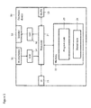
- Figure 1 shows an overview of a suitable system within which embodiments of the application can be implemented.
- Figure 1 shows an example of an apparatus or electronic device 10.
- the apparatus 10 may be used to capture, record or listen to audio signals and may function as a capture apparatus.
- the apparatus 10 may for example be a mobile terminal or user equipment of a wireless communication system when functioning as the audio capture or recording apparatus.
- the apparatus can be an audio recorder, such as an MP3 player, a media recorder/player (also known as an MP4 player), or any suitable portable apparatus suitable for recording audio or audio/video camcorder/memory audio or video recorder.
- the apparatus 10 may in some embodiments comprise an audio subsystem.
- the audio subsystem for example can comprise in some embodiments at least three microphones or array of microphones 11 for audio signal capture.
- the at least three microphones or array of microphones can be a solid state microphone, in other words capable of capturing audio signals and outputting a suitable digital format signal.
- the at least three microphones or array of microphones 11 can comprise any suitable microphone or audio capture means, for example a condenser microphone, capacitor microphone, electrostatic microphone, Electret condenser microphone, dynamic microphone, ribbon microphone, carbon microphone, piezoelectric microphone, or micro electrical-mechanical system (MEMS) microphone.
- MEMS micro electrical-mechanical system
- the microphones 11 are digital microphones, in other words configured to generate a digital signal output (and thus not requiring an analogue-to-digital converter).
- the microphones 11 or array of microphones can in some embodiments output the audio captured signal to an analogue-to-digital converter (ADC) 14.
- ADC analogue-to-digital converter
- the apparatus can further comprise an analogue-to-digital converter (ADC) 14 configured to receive the analogue captured audio signal from the microphones and outputting the audio captured signal in a suitable digital form.
- ADC analogue-to-digital converter
- the analogue-to-digital converter 14 can be any suitable analogue-to-digital conversion or processing means.
- the microphones are 'integrated' microphones containing both audio signal generating and analogue-to-digital conversion capability.
- the apparatus 10 audio subsystems further comprises a digital-to-analogue converter 32 for converting digital audio signals from a processor 21 to a suitable analogue format.
- the digital-to-analogue converter (DAC) or signal processing means 32 can in some embodiments be any suitable DAC technology.
- the audio subsystem can comprise in some embodiments a speaker 33.
- the speaker 33 can in some embodiments receive the output from the digital-to-analogue converter 32 and present the analogue audio signal to the user.
- the speaker 33 can be representative of multi-speaker arrangement, a headset, for example a set of headphones, or cordless headphones.
- the apparatus 10 is shown having both audio (speech) capture and audio presentation components, it would be understood that in some embodiments the apparatus 10 can comprise only the audio (speech) capture part of the audio subsystem such that in some embodiments of the apparatus the microphones (for speech capture) are present.
- the apparatus 10 comprises a processor 21.
- the processor 21 is coupled to the audio subsystem and specifically in some examples the analogue-to-digital converter 14 for receiving digital signals representing audio signals from the microphone 11, and the digital-to-analogue converter (DAC) 12 configured to output processed digital audio signals.
- the processor 21 can be configured to execute various program codes.
- the implemented program codes can comprise for example audio recording and audio signal processing routines.
- the apparatus further comprises a memory 22.
- the processor is coupled to memory 22.
- the memory can be any suitable storage means.
- the memory 22 comprises a program code section 23 for storing program codes implementable upon the processor 21.
- the memory 22 can further comprise a stored data section 24 for storing data, for example data that has been recorded or analysed in accordance with the application. The implemented program code stored within the program code section 23, and the data stored within the stored data section 24 can be retrieved by the processor 21 whenever needed via the memory-processor coupling.
- the apparatus 10 can comprise a user interface 15.
- the user interface 15 can be coupled in some embodiments to the processor 21.
- the processor can control the operation of the user interface and receive inputs from the user interface 15.
- the user interface 15 can enable a user to input commands to the electronic device or apparatus 10, for example via a keypad, and/or to obtain information from the apparatus 10, for example via a display which is part of the user interface 15.
- the user interface 15 can in some embodiments comprise a touch screen or touch interface capable of both enabling information to be entered to the apparatus 10 and further displaying information to the user of the apparatus 10.
- the apparatus further comprises a transceiver 13, the transceiver in such embodiments can be coupled to the processor and configured to enable a communication with other apparatus or electronic devices, for example via a wireless communications network.
- the transceiver 13 or any suitable transceiver or transmitter and/or receiver means can in some embodiments be configured to communicate with other electronic devices or apparatus via a wire or wired coupling.
- the coupling can be any suitable known communications protocol, for example in some embodiments the transceiver 13 or transceiver means can use a suitable universal mobile telecommunications system (UMTS) protocol or GSM, a wireless local area network (WLAN) protocol such as for example IEEE 802.X, a suitable short-range radio frequency communication protocol such as Bluetooth, or infrared data communication pathway (IRDA).
- UMTS universal mobile telecommunications system
- GSM Global System for Mobile communications
- WLAN wireless local area network
- Bluetooth Bluetooth
- IRDA infrared data communication pathway
- the concept of the embodiments described herein is the ability to implement directional/positional robust audio signal processing using at least three microphone inputs.
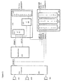
- FIG. 3 an example audio signal processor apparatus is shown according to some embodiments.
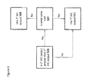
- Figure 4 the operation of the audio signal processing apparatus shown in figure 3 is described in further detail.
- the audio signal processor apparatus in some embodiments comprises a pre-processor 201.
- the pre-processor 201 can be configured to receive the audio signals from the microphones, shown in Figure 3 as the near microphones 103, 105 and the far microphone 101.
- the location of the near and far microphones can be as shown in the example configuration as shown in Figure 2 , however it would be understood that in some embodiments that other configurations and/or numbers of microphones can be used.
- the embodiments as described herein feature audio signals received directly from the microphones as the input signals it would be understood that in some embodiments the input audio signals can be pre-stored or stored audio signals.
- the input audio signals are audio signals retrieved from memory. These retrieved audio signals can in some embodiments be recorded microphone audio signals.
- step 301 The operation of receiving the audio/microphone input is shown in Figure 4 by step 301.
- the pre-processor 201 can in some embodiments be configured to perform any suitable pre-processing operation.
- the pro-processor can be configured to perform operation such as: to calibrate the microphone audio signals; to determine whether the microphones are free from any impairment; to correct the audio signals where impairment is determined; to determine whether any of the microphones are operating in strong wind; and to determine which of the microphone inputs is the main microphone.
- the microphones can be compared to determine which has the loudest input signal and is therefore determined to be directed towards the user.
- the near microphone 103 is determined to be the main microphone and therefore the output of the pre-processor determines the main microphone output as the near microphone 103 input audio signal.
- pre-processing such as a determination of the main microphone input is shown in Figure 4 by step 303.
- the main microphone audio signal and other determined near microphone audio signals can then be passed to the beamformer 203.
- the audio signal processor comprises a beamformer 203.
- the beamformer 203 can be configured to receive the near microphone inputs, such as shown in Figure 3 by the main microphone (MAINM) coupling and the other near microphone coupling from the pre-processor.
- the beamformer 203 can then be configured to generate at least two beam audiosignals.
- the beamformer 203 can be configured to generate a main beam (MAINB) and anti-beam (ANTIB) audio signals.
- MAINB main beam
- ANTIB anti-beam
- the beamformer 203 can be configured to generate any suitable beamformed audio signal from the main microphone and other near microphone inputs.
- the main beam audio signal is one where the local speech is substantially passed without processing while the noise coming from the opposite direction is substantially attenuated
- the anti-beam audio signal is one where the local speech is heavily attenuated or substantially attenuated while the noise from the other directions is not attenuated.
- the beamformer 203 can in some embodiments be configured to output the beam audio signals, for example, the main beam and the anti-beam audio signals, to the adaptive interference canceller (AIC) 205 and to the spatial voice activity detector 207.
- AIC adaptive interference canceller
- the beamformer operates in the time domain and employs finite impulse response (FIR) filters to attenuate some directions.
- FIR finite impulse response
- step 305 The operation of beamforming the near microphone audio signals to generate a main beam and anti-beam audio signals is shown in Figure 4 by step 305.
- the audio processor comprises an adaptive interference canceller (AIC) 205.
- the adaptive interference canceller (AIC) 205 in some embodiments, comprises at least two audio interference canceller modules. Each of the audio canceller modules are configured to provide a suitable audio processing output for various combination of microphones inputs.
- the audio interference canceller 205 comprises a primary (or first or main) audio interference canceller (AIC) module 211, a secondary (or secondary) AIC module 213 and a comparator 215 configured to receive the outputs of the primary AIC module 211 and the secondary AIC module 213.
- AIC audio interference canceller
- the primary audio interference canceller module 211 can be configured to receive the audio signals from the main beam and anti-beam audio signals and determine a first audio interference canceller module output using the main beam as a speech and noise input and the anti-beam as a noise reference and 'leaked' speech input.
- the primary audio interference canceller module 211 can be configured to then pass the processed module output to a comparator 215.
- the secondary AIC module 213 is configured to receive as inputs the main beam audio signal and the far microphone audio signal (in other words the audio information from all three microphones).
- the secondary AIC module 213 can be configured to generate an adaptive interference cancellation output using the main beam audio signal as a speech and noise input and the far microphone audio signal as a noise reference and 'leaked' speech input
- the secondary audio interference canceller module 213 can then be configured to output a secondary adaptive interference cancellation output to the comparator 215.
- the adaptive interference canceller 205 as described herein further comprises a comparator 215 configured to receive the outputs of the at least two AIC modules.
- these AIC module outputs are the primary AIC module 211 and the secondary AIC module 213, however it would be understood that in some embodiments any number of AIC modules can be used and therefore the comparator 215 receive any number of module signals.
- the comparator 215 can then be configured to compare the AIC module outputs and output the one which has the highest output signal level.
- the comparator 215 can furthermore be configured to have a preferred or default output and only switch to a different module output where there is a considerable difference.
- the comparator 215 can be configured to determine whether the signal level difference between two AIC modules is greater than a threshold value (for example 2dB) and only switch when the threshold value is passed.
- the comparator 215 can be configured to output the primary AIC module 211 output while the primary AIC module output is equal to or greater than the secondary AIC module output and only switch to the secondary AIC module output when the secondary AIC module output 213 is 2dB greater than the primary AIC module output.
- the AIC 205 which as shown in this example comprises two parallel AIC modules operates in the time domain employing adaptive filters such as shown herein in Figure 7 .
- any suitable implementation can be employed in some embodiments such as series or hybrid series-parallel AIC implementations..
- the AIC 205 can be configured to receive control inputs. These control inputs can be used to control the behaviour of the AIC based on environmental factors such as determining whether the microphone is operating in wind (and therefore at least one microphone is generating large amounts of wind noise) or operating in a wind shadow.
- the audio processor is configured to be optimised for speech processing and thus a voice activity detection process occurs in order that the audio interference canceller operates to optimise voice signal to background noise. It would be understood that in some embodiments the inputs to the AIC modules are normalised.
- the AIC output can be passed to a single channel noise suppressor.
- a single channel noise suppressor is a known component which based on a noise estimate can perform further noise suppression.
- the single noise suppressor and the operation of the single channel noise suppressor is not described in further detail here but it would be understood that the single channel noise suppressor receives an input of a noisy speech signal, and from the noisy speech signal estimates the background noise. The estimate of the background noise being then used to improve the noisy speech signal, for example by applying a Weiner filter or other known method).
- the estimate of the noise is made from the noisy speech signal when the noisy speech signal is determined to be noise only for example based on an output from a voice activity detector and/or as described herein a spatial voice activity detector (spatial VAD).
- the single channel noise suppressor typically operates within the frequency domain, however it would be understood that in some embodiments a time domain single channel noise suppressor could be employed.
- the single channel noise suppressor can thus use the spatial VAD information to attenuate non-stationary background noise such as babble, clicks, radio, competing speakers, and children that try to get your attention during phone calls.
- non-stationary background noise such as babble, clicks, radio, competing speakers, and children that try to get your attention during phone calls.
- the audio processor in some embodiments can comprise a spatial voice activity detector 207.
- the spatial voice activity detector 207 can in some embodiments be configured to receive as inputs the main beam, anti-beam, main microphone and far microphone audio signals.
- the operation of the spatial voice activity detector is to force the single channel noise suppressor to only update the noise estimate when the audio signal comprises noise (or in other words to not update the noise estimate when the audio signal comprises speech from the expected direction)
- the spatial voice security detector 207 comprises a normaliser 221.
- the normaliser 221 can in some embodiments be configured to receive the main microphone, the far microphone, the main beam and anti-beam audio signals and perform a normalisation process on these audio signals.
- the normalisation process is performed such that levels of the audio signals during the stationary noise are substantially the same. This normalisation process is performed in order to prevent any bias due to microphone sensitivity variations or beam sensitivity variations.
- the normaliser is configured to perform a smoothed signal minima determination on the audio signals. In such embodiments the normaliser can then determine a ratio between the minima of the inputs to determine a normalisation gain factor to be applied to each input to normalise the stationary noise. In some embodiments the normaliser can further be configured to determine spatial stationary noise (for example road on one side and forest on the other side of the apparatus) and in such embodiments adapt the normalisation to the noise levels and prevent the marking of the noise as speech. Similar or same normalization can be carried out for controlling adaptive filtering blocks in the AIC 205. As such in some embodiments a common normaliser can be employed for both the AIC (and therefore in some embodiments the AIC modules) and the spatial VAD such that the AIC modules and the spatial VAD receives inputs of normalised audio inputs.
- the Nearmics audio signals are calibrated prior to any processing, for example beamforming, (such that only small differences in mic sensitivities are allowed) in order to have proper beams that point where they should (in these examples towards a user's mouth and in the opposite direction).
- beamforming such that only small differences in mic sensitivities are allowed
- the Noise level in the mainbeam audio signal is typically lower than the farmic audio signal, because beamforming reduces background noise.
- This normalisation can be performed after beamforming
- mainbeam and antibeam audio signals are the same for ambient noise (for example inside a car), the noise levels would not necessarily be the same for directional stationary noise (for example when a user is standing on one side of a street). Therefore in some embodiments the mainbeam and antibeam audio signals have to be normalized after beamforming for spatial VAD and AIC's internal control.
- Noiselevels in the first nearmic and farmic audio signals are generally approximately the same, but since these signals need not to be calibrated against microphone sensitivity differences in some embodiments the first nearmic and farmic audio signals are normalized for spatial VAD (They are not used in AIC as an input signal pair in the examples shown herein).
- the spatial voice activity detector 207 comprises a frequency filter 223.
- the frequency filter 223 can be configured to receive the normalised audio signal inputs and frequency filter the audio signals.
- the microphone and/or beamformed audio signals signals (such as the main microphone, and far microphone audio signals are low pass frequency filtered.
- the microphone signals (or beamformed audio signals) main beam-'farmic' comparison and also to the main microphone (first nearmic) - farmic comparison (in other words the comparison of the microphone signals) can implement a low pass filter with a pass band of e.g. about 0-800 Hz.
- the beam audio signals for example the main beam and the anti-beam audio signals are also frequency filtered.
- the frequency filtering of the beam audio signals can be determined based on the beam design of the beamformer 203. This is because the beams are designed so that the greatest separation is over a certain frequency range. An example of the frequency pass band for the main beam and anti-beam audio signals comparison would be approximately 500Hz to 2500 Hz.
- the filtered audio signals can then be passed to a ratio comparator 225.
- the spatial voice activity detector 207 comprises a ratio comparator 225.
- the ratio comparator 225 can be configured to receive the frequency filtered normalised audio signals and generate comparison pairs to determine whether the audio signals comprise spatially orientated voice information.
- the comparison pairs are:
- the spatial VAD 207 output can be employed as a control input to a single channel noise suppressor as discussed herein or other suitable noise suppressor such that when the spatial VAD 207 determines that each of the ratios is similar or substantially similar then the single channel noise suppressor or other suitable noise suppressor can use the background noise estimate whereas where the signal level differs between any of the comparisons then the background noise estimate is not used (and in some embodiments an older estimate is used.
- the AIC determines whether the secondary AIC output is stronger than the primary AIC output.
- the three microphone processing operation is used, in other words the secondary AIC is output by the comparator.
- the primary AIC output is used.
- FIG. 7 an example AIC is used wherein a first microphone or beam for the noise reference and leaked speech is passed as a positive input to a first adder 601.
- the first adder 601 outputs to a first adaptive filter 603 control input and to a second adaptive filter 605 data input.
- the first adder 601 further receives as a negative input the output of the first adaptive filter 603.
- the first adaptive filter 603 receives as a data input the speech and noise microphone or beam audio signal.
- the speech and noise microphone or beam audio signal is further passed to a delay 607.
- the output of the delay 607 is passed as a positive input to a second adder 609.
- the second adder 609 receives as a negative input the output of the second adaptive filter 605.
- the output of the second adder 609 is then output as the signal output and used as the control input to the second adaptive filter 605.
- Wiener filtering operates as a suppression method that can be carried out to single channel audio signal s(k).
- the example shown in Figure 7 would appear to allow the AIC to remove all noise, this is not achieved in practical situations as typically there is output background noise that is further reduced in some embodiments by the single channel noise suppressor.
- the electronic device 10 may be any device incorporating an audio recordal system for example a type of wireless user equipment, such as mobile telephones, portable data processing devices or portable web browsers, as well as wearable devices.
- wireless user equipment such as mobile telephones, portable data processing devices or portable web browsers, as well as wearable devices.
- the various embodiments of the invention may be implemented in hardware or special purpose circuits, software, logic or any combination thereof.
- some aspects may be implemented in hardware, while other aspects may be implemented in firmware or software which may be executed by a controller, microprocessor or other computing device, although the invention is not limited thereto.
- firmware or software which may be executed by a controller, microprocessor or other computing device, although the invention is not limited thereto.
- While various aspects of the invention may be illustrated and described as block diagrams, flow charts, or using some other pictorial representation, it is well understood that these blocks, apparatus, systems, techniques or methods described herein may be implemented in, as non-limiting examples, hardware, software, firmware, special purpose circuits or logic, general purpose hardware or controller or other computing devices, or some combination thereof.
- the embodiments of this invention may be implemented by computer software executable by a data processor of the mobile device, such as in the processor entity, or by hardware, or by a combination of software and hardware.
- any blocks of the logic flow as in the Figures may represent program steps, or interconnected logic circuits, blocks and functions, or a combination of program steps and logic circuits, blocks and functions.
- the software may be stored on such physical media as memory chips, or memory blocks implemented within the processor, magnetic media such as hard disk or floppy disks, and optical media such as for example DVD and the data variants thereof, CD.
- the memory may be of any type suitable to the local technical environment and may be implemented using any suitable data storage technology, such as semiconductor-based memory devices, magnetic memory devices and systems, optical memory devices and systems, fixed memory and removable memory.
- the data processors may be of any type suitable to the local technical environment, and may include one or more of general purpose computers, special purpose computers, microprocessors, digital signal processors (DSPs), application specific integrated circuits (ASIC), gate level circuits and processors based on multi-core processor architecture, as non-limiting examples.
- Embodiments of the inventions may be practiced in various components such as integrated circuit modules.
- the design of integrated circuits is by and large a highly automated process.
- Complex and powerful software tools are available for converting a logic level design into a semiconductor circuit design ready to be etched and formed on a semiconductor substrate.
- Programs such as those provided by Synopsys, Inc. of Mountain View, California and Cadence Design, of San Jose, California automatically route conductors and locate components on a semiconductor chip using well established rules of design as well as libraries of pre-stored design modules.
- the resultant design in a standardized electronic format (e.g., Opus, GDSII, or the like) may be transmitted to a semiconductor fabrication facility or "fab" for fabrication.
Landscapes
- Engineering & Computer Science (AREA)
- Physics & Mathematics (AREA)
- Acoustics & Sound (AREA)
- Signal Processing (AREA)
- Health & Medical Sciences (AREA)
- Human Computer Interaction (AREA)
- Audiology, Speech & Language Pathology (AREA)
- Computational Linguistics (AREA)
- Multimedia (AREA)
- Quality & Reliability (AREA)
- General Health & Medical Sciences (AREA)
- Otolaryngology (AREA)
- Mathematical Physics (AREA)
- Circuit For Audible Band Transducer (AREA)
Abstract
Description
- The present application relates to apparatus and methods for the implementation of noise reduction or audio enhancement in multi-microphone systems and specifically but not only implementation of noise reduction or audio enhancement in multi-microphone systems within mobile apparatus.
- Audio recording systems can make use of more than one microphone to pick-up and record audio in the surrounding environment.
- These multi-microphone systems (or MMic systems) permit the implementation of digital signal processing such as speech enhancement to be applied to the microphone outputs. The intention in speech enhancement is to use mathematical methods to improve the quality of speech, presented as digital signals. One speech enhancement implementation is concerned with uplink processing the audio signals from three inputs or microphones.
- According to a first aspect there is provided a method comprising: receiving at least three microphone audio signals, the at least three microphone audio signals comprising at least two near microphone audio signals generated by at least two near microphones located near to an desired audio source and at least one far microphone audio signal generated by a far microphone located further from the desired audio source than the at least two near microphones; generating a first processed audio signal based on a first selection from the at least three microphone audio signals, the first selection being from the near microphone audio signals; generating at least one further processed audio signal based on at least one further selection from the at least three microphone audio signals, the at least one further selection from the at least three microphone audio signals, the second selection being from all of the microphone signals; determining from the first processed audio signal and the at least one further processed audio signal the audio signal with greater noise suppression.
- The greater noise suppression may comprise improved noise suppression.
- Receiving at least three microphone audio signals may comprise: receiving a first microphone audio signal from a first near microphone located substantially at a front of an apparatus; receiving a second microphone audio signal from a second near microphone located substantially at a rear of the apparatus; and receiving a third microphone audio signal from a far microphone located substantially at the opposite end from the first and second microphones.
- Generating a first processed audio signal based on a first selection from the at least three microphone audio signals may comprise generating a first processed audio signal based on a main beam audio signal based on the first and second microphone audio signals and an anti-beam audio signal based on the first and second microphone audio signals.
- Generating at least one further processed audio signal based on at least one further selection from the at least three microphone audio signals comprises generating a further processed audio signal based on a main beam audio signal based on the first and second microphone audio signals and the third microphone audio signal.
- The method may further comprise: generating a main beam audio signal by: applying a first finite impulse response filter to the first audio signal; applying a second finite impulse response filter to the second audio signal; and combining the output of the first impulse response filter and the second finite response filter to generate the main beam audio signal; and generating an anti-beam audio signal by: applying a third finite impulse response filter to the first audio signal; applying a fourth finite impulse response filter to the second audio signal; and combining the output of the third impulse response filter and the fourth finite response filter to generate the anti-beam audio signal.
- Generating a further processed audio signal based on a main beam audio signal based on the first and second microphone audio signals and the third microphone audio signal may comprise filtering the main beam audio signal based on the third microphone audio signal.
- Generating a first processed audio signal based on a main beam audio signal based on the first and second microphone audio signals and an anti-beam audio signal based on the first and second microphone audio signals may comprise filtering the main beam audio signal based on the anti-beam audio signal.
- Generating a first processed audio signal based on a first selection from the at least three microphone audio signals may comprise: selecting as a first processing input at least one of: one of the at least three microphone audio signals; and a beamformed audio signal based on at least two of the at least three microphone audio signals, the selections being from the near microphone audio signals; selecting as a second processing input at least one of: one of the at least three microphone audio signals; and a beamformed audio signal based on the at least three microphone audio signals, the selections being from the near microphone audio signals; filtering the first processing input based on the second processing input to generate the first processed audio signal.
- Generating at least one further processed audio signal based on at least one further selection from the at least three microphone audio signals may comprise: selecting as a first processing input at least one of: one of the at least three microphone audio signals; and a beamformed audio signal based on at least two of the at least three microphone audio signals, the selections being from all of the microphone signals; selecting as a second processing input at least one of: one of the at least three microphone audio signals; and a beamformed audio signal based on at least two of the at least three microphone audio signals, the selections being from all of the microphone signals; filtering the first processing input based on the second processing input to generate the at least one further processed audio signal.
- Filtering the first processing input based on the second processing input to generate the at least one further processed audio signal may comprise noise suppression filtering the first processing input based on the second processing input.
- The method may further comprise beamforming at least two of the at least three microphone audio signals to generate a beamformed audio signal.
- Beamforming at least two of the at least three microphone audio signals to generate a beamformed audio signal may comprise: applying a first finite impulse response filter to a first of the at least two of the at least three microphone audio signals; applying a second finite impulse response filter to a second of the at least two of the at least three microphone audio signals; and combining the output of the first impulse response filter and the second finite response filter to generate the beamformed audio signal.
- The method may further comprise single channel noise suppressing the audio signal with greater noise suppression, wherein single channel noise suppressing comprises: generating an indicator showing whether a period of the audio signal comprises a lack of speech components or is significantly noise; estimating and updating a background noise from the audio signal when the indicator shows the period of the audio signal comprises a lack of speech components or is significantly noise; processing the audio signal based on the background noise estimate to generate a noise suppressed audio signal.
- Generating an indicator showing whether a period of the audio signal comprises a lack of speech components or is significantly noise may comprise: normalising a selection from the at least three microphone audio signals, wherein the selection comprises: beamformed audio signals of at least two of the at least three microphone audio signals; and microphone audio signals; filtering the normalised selections from the at least three microphone audio signals; comparing the filtered normalised selections to determine a power difference ratio; generating the indicator showing a period of the audio signal comprises a lack of speech components or is significantly noise where at least one comparison of filtered normalised selections has a power difference ratio greater than a determined threshold.
- Determining from the first processed audio signal and the at least one further processed audio signal the audio signal with greater noise suppression may comprise at least one of: determining from the first processed audio signal and the at least one further processed audio signal the audio signal with the highest signal level output; and determining from the first processed audio signal and the at least one further processed audio signal the audio signal with the highest power level output.
- According to a second aspect there is provided an apparatus comprising at least one processor and at least one memory including computer code for one or more programs, the at least one memory and the computer code configured to with the at least one processor cause the apparatus to: receive at least three microphone audio signals, the at least three microphone audio signals comprising at least two near microphone audio signals generated by at least two near microphones located near to an desired audio source and at least one far microphone audio signal generated by a far microphone located further from the desired audio source than the at least two near microphones; generate a first processed audio signal based on a first selection from the at least three microphone audio signals, the first selection being from the near microphone audio signals; generate at least one further processed audio signal based on at least one further selection from the at least three microphone audio signals, the at least one further selection from the at least three microphone audio signals, the second selection being from all of the microphone signals; determine from the first processed audio signal and the at least one further processed audio signal the audio signal with greater noise suppression.
- Receiving at least three microphone audio signals may cause the apparatus to: receive a first microphone audio signal from a first near microphone located substantially at a front of an apparatus; receive a second microphone audio signal from a second near microphone located substantially at a rear of the apparatus; and receive a third microphone audio signal from a far microphone located substantially at the opposite end from the first and second microphones.
- Generating a first processed audio signal based on a first selection from the at least three microphone audio signals may cause the apparatus to generate a first processed audio signal based on a main beam audio signal based on the first and second microphone audio signals and an anti-beam audio signal based on the first and second microphone audio signals.
- Generating at least one further processed audio signal based on at least one further selection from the at least three microphone audio signals may cause the apparatus to generate a further processed audio signal based on a main beam audio signal based on the first and second microphone audio signals and the third microphone audio signal.
- The apparatus may be further caused to: generate a main beam audio signal by applying a first finite impulse response filter to the first audio signal; applying a second finite impulse response filter to the second audio signal; and combining the output of the first impulse response filter and the second finite response filter to generate the main beam audio signal; and generate an anti-beam audio signal by: applying a third finite impulse response filter to the first audio signal; applying a fourth finite impulse response filter to the second audio signal; and combining the output of the third impulse response filter and the fourth finite response filter to generate the anti-beam audio signal.
- Generating a further processed audio signal based on a main beam audio signal based on the first and second microphone audio signals and the third microphone audio signal may cause the apparatus to filter the main beam audio signal based on the third microphone audio signal.
- Generating a first processed audio signal based on a main beam audio signal based on the first and second microphone audio signals and an anti-beam audio signal based on the first and second microphone audio signals may cause the apparatus to filter the main beam audio signal based on the anti-beam audio signal.
- Generating a first processed audio signal based on a first selection from the at least three microphone audio signals may cause the apparatus to: select as a first processing input at least one of: one of the at least three microphone audio signals; and a beamformed audio signal based on at least two of the at least three microphone audio signals, the selections being from the near microphone audio signals; select as a second processing input at least one of: one of the at least three microphone audio signals; and a beamformed audio signal based on the at least three microphone audio signals, the selections being from the near microphone audio signals; filter the first processing input based on the second processing input to generate the first processed audio signal.
- Generating at least one further processed audio signal based on at least one further selection from the at least three microphone audio signals may cause the apparatus to: select as a first processing input at least one of: one of the at least three microphone audio signals; and a beamformed audio signal based on at least two of the at least three microphone audio signals, the selections being from all of the microphone signals; select as a second processing input at least one of: one of the at least three microphone audio signals; and a beamformed audio signal based on at least two of the at least three microphone audio signals, the selections being from all of the microphone signals; filter the first processing input based on the second processing input to generate the at least one further processed audio signal.
- Filtering the first processing input based on the second processing input to generate the at least one further processed audio signal may cause the apparatus to noise suppression filter the first processing input based on the second processing input.
- The apparatus may be caused to beamform at least two of the at least three microphone audio signals to generate a beamformed audio signal.
- Beamforming at least two of the at least three microphone audio signals to generate a beamformed audio signal may cause the apparatus to: apply a first finite impulse response filter to a first of the at least two of the at least three microphone audio signals; apply a second finite impulse response filter to a second of the at least two of the at least three microphone audio signals; and combine the output of the first impulse response filter and the second finite response filter to generate the beamformed audio signal.
- The apparatus may be caused to single channel noise suppress the audio signal with greater noise suppression, wherein single channel noise suppressing may cause the apparatus to: generate an indicator showing whether a period of the audio signal comprises a lack of speech components or is significantly noise; estimate and update a background noise from the audio signal when the indicator shows the period of the audio signal comprises a lack of speech components or is significantly noise; process the audio signal based on the background noise estimate to generate a noise suppressed audio signal.
- Generating an indicator showing whether a period of the audio signal comprises a lack of speech components or is significantly noise may cause the apparatus to: normalise a selection from the at least three microphone audio signals, wherein the selection comprises: beamformed audio signals of at least two of the at least three microphone audio signals; and microphone audio signals; filter the normalised selections from the at least three microphone audio signals; compare the filtered normalised selections to determine a power difference ratio; generate the indicator showing a period of the audio signal comprises a lack of speech components or is significantly noise where at least one comparison of filtered normalised selections has a power difference ratio greater than a determined threshold.
- Determining from the first processed audio signal and the at least one further processed audio signal the audio signal with greater noise suppression may cause the apparatus to perform at least one of: determine from the first processed audio signal and the at least one further processed audio signal the audio signal with the highest signal level output; and determine from the first processed audio signal and the at least one further processed audio signal the audio signal with the highest power level output.
- According to a third aspect there is provided an apparatus comprising: an input configured to receive at least three microphone audio signals, the at least three microphone audio signals comprising at least two near microphone audio signals generated by at least two near microphones located near to an desired audio source and at least one far microphone audio signal generated by a far microphone located further from the desired audio source than the at least two near microphones; a first interference canceller module configured to generate a first processed audio signal based on a first selection from the at least three microphone audio signals, the first selection being from the near microphone audio signals; at least one further interference canceller module configured to generate at least one further processed audio signal based on at least one further selection from the at least three microphone audio signals, the at least one further selection from the at least three microphone audio signals, the second selection being from all of the microphone signals; a comparator configured to determine from the first processed audio signal and the at least one further processed audio signal the audio signal with greater noise suppression.
- The input may be configured to: receive a first microphone audio signal from a first near microphone located substantially at a front of an apparatus; receive a second microphone audio signal from a second near microphone located substantially at a rear of the apparatus; and receive a third microphone audio signal from a far microphone located substantially at the opposite end from the first and second microphones.
- The first interference canceller module may be configured to generate a first processed audio signal based on a main beam audio signal based on the first and second microphone audio signals and an anti-beam audio signal based on the first and second microphone audio signals.
- The at least one further interference canceller module may be configured to generate a further processed audio signal based on a main beam audio signal based on the first and second microphone audio signals and the third microphone audio signal.
- The apparatus may further comprise: a main beam beamformer configured to generate a main beam audio signal comprising a first finite impulse response filter configured to receive the first audio signal; a second finite impulse response filter configured to receive the second audio signal; and a combiner configured to combine the output of the first impulse response filter and the second finite response filter to generate the main beam audio signal; and an anti-beam beamformer configured to generate an anti-beam audio signal comprising: a third finite impulse response filter configured to receive the first audio signal; a fourth finite impulse response filter configured to receive the second audio signal; and a combiner configured to combine the output of the third impulse response filter and the fourth finite response filter to generate the anti-beam audio signal.
- The at least one further interference canceller module may comprise a filter configured to filter the main beam audio signal based on the third microphone audio signal.
- The first interference canceller module may comprise a filter configured to filter the main beam audio signal based on the anti-beam audio signal.
- The first interference canceller module may comprise: a selector configured to select as a first processing input at least one of: one of the at least three microphone audio signals; and a beamformed audio signal based on at least two of the at least three microphone audio signals, the selections being from the near microphone audio signals; a second selector configured to select as a second processing input at least one of: one of the at least three microphone audio signals; and a beamformed audio signal based on the at least three microphone audio signals, the selections being from the near microphone audio signals; a filter configured to filter the first processing input based on the second processing input to generate the first processed audio signal.
- The at least one further interference generator may comprise: a selector configured to select as a first processing input at least one of: one of the at least three microphone audio signals; and a beamformed audio signal based on at least two of the at least three microphone audio signals, the selections being from all of the microphone signals; a second selector configured to select as a second processing input at least one of: one of the at least three microphone audio signals; and a beamformed audio signal based on at least two of the at least three microphone audio signals, the selections being from all of the microphone signals; a filter configured to filter the first processing input based on the second processing input to generate the at least one further processed audio signal.
- The filter may be configured to noise suppression filter the first processing input based on the second processing input.
- The apparatus may comprise a beamformer configured to beamform at least two of the at least three microphone audio signals to generate a beamformed audio signal.
- The beamformer may comprise: a first finite impulse response filter configured to filter a first of the at least two of the at least three microphone audio signals; a second finite response filter configured to filter to a second of the at least two of the at least three microphone audio signals; and a combiner configured to combine the output of the first impulse response filter and the second finite response filter to generate the beamformed audio signal.
- The apparatus may comprise a single channel noise suppressor configured to noise suppress the audio signal with greater noise suppression, the single channel noise suppressor may comprise: an input configured to receive an indicator showing whether a period of the audio signal comprises a lack of speech components or is significantly noise; an estimator configured to estimate and update a background noise from the audio signal when the indicator shows the period of the audio signal comprises a lack of speech components or is significantly noise; a filter configured to process the audio signal with greater noise suppression based on the background noise estimate to generate a noise suppressed audio signal.
- The apparatus may comprise a voice activity detector configured to generate an indicator showing whether a period of the audio signal comprises a lack of speech components or is significantly noise comprising: a normaliser configured to normalise a selection from the at least three microphone audio signals, wherein the selection comprises: beamformed audio signals of at least two of the at least three microphone audio signals; and microphone audio signals; a filter configured to filter the normalised selections from the at least three microphone audio signals; a comparator configured to compare the filtered normalised selections to determine a power difference ratio; an indicator generator configured to generate the indicator showing a period of the audio signal with greater noise suppression comprises a lack of speech components or is significantly noise where at least one comparison of filtered normalised selections has a power difference ratio greater than a determined threshold.
- The comparator configured to determine from the first processed audio signal and the at least one further processed audio signal the audio signal with greater noise suppression may be configured to perform at least one of: determine from the first processed audio signal and the at least one further processed audio signal the audio signal with the highest signal level output; and determine from the first processed audio signal and the at least one further processed audio signal the audio signal with the highest power level output.
- According to a fourth aspect there is provided an apparatus comprising: means for receiving at least three microphone audio signals, the at least three microphone audio signals comprising at least two near microphone audio signals generated by at least two near microphones located near to an desired audio source and at least one far microphone audio signal generated by a far microphone located further from the desired audio source than the at least two near microphones; means for generating a first processed audio signal based on a first selection from the at least three microphone audio signals, the first selection being from the near microphone audio signals; means for generating at least one further processed audio signal based on at least one further selection from the at least three microphone audio signals, the at least one further selection from the at least three microphone audio signals, the second selection being from all of the microphone signals; means for determining from the first processed audio signal and the at least one further processed audio signal the audio signal with greater noise suppression.
- The means for receiving at least three microphone audio signals may comprise: means for receiving a first microphone audio signal from a first near microphone located substantially at a front of an apparatus; means for receiving a second microphone audio signal from a second near microphone located substantially at a rear of the apparatus; and means for receiving a third microphone audio signal from a far microphone located substantially at the opposite end from the first and second microphones.
- The means for generating a first processed audio signal based on a first selection from the at least three microphone audio signals may comprise means for generating a first processed audio signal based on a main beam audio signal based on the first and second microphone audio signals and an anti-beam audio signal based on the first and second microphone audio signals.
- The means for generating at least one further processed audio signal based on at least one further selection from the at least three microphone audio signals may comprise means for generating a further processed audio signal based on a main beam audio signal based on the first and second microphone audio signals and the third microphone audio signal.
- The apparatus may further comprise: means for generating a main beam audio signal comprising: means for applying a first finite impulse response filter to the first audio signal; means for applying a second finite impulse response filter to the second audio signal; and means for combining the output of the first impulse response filter and the second finite response filter to generate the main beam audio signal; and means for generating an anti-beam audio signal may comprise: means for applying a third finite impulse response filter to the first audio signal; means for applying a fourth finite impulse response filter to the second audio signal; and means for combining the output of the third impulse response filter and the fourth finite response filter to generate the anti-beam audio signal.
- The means for generating a further processed audio signal based on a main beam audio signal based on the first and second microphone audio signals and the third microphone audio signal may comprise means for filtering the main beam audio signal based on the third microphone audio signal.
- The means for generating a first processed audio signal based on a main beam audio signal based on the first and second microphone audio signals and an anti-beam audio signal based on the first and second microphone audio signals may comprise means for filtering the main beam audio signal based on the anti-beam audio signal.
- The means for generating a first processed audio signal based on a first selection from the at least three microphone audio signals may comprise: means for selecting as a first processing input at least one of: one of the at least three microphone audio signals; and a beamformed audio signal based on at least two of the at least three microphone audio signals, the selections being from the near microphone audio signals; means for selecting as a second processing input at least one of: one of the at least three microphone audio signals; and a beamformed audio signal based on the at least three microphone audio signals, the selections being from the near microphone audio signals; means for filtering the first processing input based on the second processing input to generate the first processed audio signal.
- The means for generating at least one further processed audio signal based on at least one further selection from the at least three microphone audio signals may comprise: means for selecting as a first processing input at least one of: one of the at least three microphone audio signals; and a beamformed audio signal based on at least two of the at least three microphone audio signals, the selections being from all of the microphone signals; means for selecting as a second processing input at least one of: one of the at least three microphone audio signals; and a beamformed audio signal based on at least two of the at least three microphone audio signals, the selections being from all of the microphone signals; means for filtering the first processing input based on the second processing input to generate the at least one further processed audio signal.
- The means for filtering the first processing input based on the second processing input to generate the at least one further processed audio signal comprises noise suppression filtering the first processing input based on the second processing input.
- The apparatus may further comprise means for beamforming at least two of the at least three microphone audio signals to generate a beamformed audio signal.
- The means for beamforming at least two of the at least three microphone audio signals to generate a beamformed audio signal may comprise: means for applying a first finite impulse response filter to a first of the at least two of the at least three microphone audio signals; means for applying a second finite impulse response filter to a second of the at least two of the at least three microphone audio signals; and means for combining the output of the first impulse response filter and the second finite response filter to generate the beamformed audio signal.
- The apparatus may further comprise means for single channel noise suppressing the audio signal with greater noise suppression, wherein the means for single channel noise suppressing may comprise: means for generating an indicator showing whether a period of the audio signal comprises a lack of speech components or is significantly noise; means for estimating and updating a background noise from the audio signal when the indicator shows the period of the audio signal comprises a lack of speech components or is significantly noise; means for processing the audio signal based on the background noise estimate to generate a noise suppressed audio signal.
- The means for generating an indicator showing whether a period of the audio signal comprises a lack of speech components or is significantly noise may comprise: means for normalising a selection from the at least three microphone audio signals, wherein the selection comprises: beamformed audio signals of at least two of the at least three microphone audio signals; and microphone audio signals; means for filtering the normalised selections from the at least three microphone audio signals; means for comparing the filtered normalised selections to determine a power difference ratio; means for generating the indicator showing a period of the audio signal comprises a lack of speech components or is significantly noise where at least one comparison of filtered normalised selections has a power difference ratio greater than a determined threshold.
- The means for determining from the first processed audio signal and the at least one further processed audio signal the audio signal with greater noise suppression comprises at least one of: means for determining from the first processed audio signal and the at least one further processed audio signal the audio signal with the highest signal level output; and means for determining from the first processed audio signal and the at least one further processed audio signal the audio signal with the highest power level output.
- Embodiments of the present application aim to address problems associated with the state of the art.
- For better understanding of the present application, reference will now be made by way of example to the accompanying drawings in which:
-
Figure 1 shows schematically an apparatus suitable for being employed in some embodiments; -
Figure 2 shows schematically an example of a three microphone apparatus suitable for being employed in some embodiments; -
Figure 3 shows schematically a signal processor for a multi-microphone system according to some embodiments; -
Figure 4 shows schematically a flow diagram of the operation of the signal processor for the multi-microphone system as shown inFigure 3 according to some embodiments; -
Figure 5 shows schematically example gain diagrams of the mainbeam and antibeam audio signal beams according to some embodiments; -
Figure 6 shows schematically an example flow diagram of the operation of the signal processor based on a control input according to some embodiments; and -
Figure 7 shows an example adaptive interference canceller according to some embodiments. - The following describes in further detail suitable apparatus and possible mechanisms for the provision of the signal processing within multi-microphone systems. Some digital signal processing speech enhancement implementations use three microphone signals (from the available number of microphones on the apparatus or coupled to the apparatus). Two of the microphones or input signals originate from 'nearmics', (in other words microphones that are located close to each other such as at the bottom of the device) and a third microphone, 'farmic', located further away in the other end of the apparatus or device. An example of such an
apparatus 10 is shown inFigure 2 which shows the apparatus with a first microphone (mic1) 101, a front 'nearmic', located towards the bottom of the apparatus and facing the display or front of the apparatus, a second microphone (mic2) 103, a rear 'nearmic', shown by the dashed oval and located towards the bottom of the apparatus and on the opposite face to the display (or otherwise on the rear of the apparatus) and a third microphone (mic3) 105, a 'farmic', located on the 'top' of theapparatus 10. Although the following examples are described with respect to a 3 microphone system configuration it would be understood that in some embodiments the system can comprise more than 3 microphones from which a suitable selection of 3 microphones can be made. - With two or more nearmics it is possible to form two directional beams from the audio signals generated from the microphones. These can for example as shown in
Figure 5 be a 'mainbeam' 401 and 'antibeam' 403. In the 'mainbeam' local speech is substantially passed while noise coming from opposite direction is significantly attenuated. In the 'antibeam' local speech is substantially attenuated while noise from other directions is substantially passed. In such situations the level of ambient noise is almost the same in both beams. - These beams (the main- and antibeams) can in some embodiments be used in further digital signal processing to further reduce remaining background noise from the main beam audio signal using an adaptive interference canceller (AIC) and spectral subtraction.
- The adaptive interference canceller (AIC) with two near microphone audio signals can perform a first method to further cancel noise from the main beam. Although with one nearmic audio signal and one farmic audio signal beamforming is not possible, AIC can be used with microphone signals directly. Furthermore noise can be further reduced using spectral subtraction.
- The first method using beam forming of the microphone audio signals to reduce noise is understood to provide efficient noise reductions, but it is sensitive to how the device is held. The second method using direct microphone audio signals is more orientation robust, but does not provide as efficient a noise reduction.
- In both methods a spatial voice activity detector (VAD) can be used to improve noise suppression compared to single channel case with no directional information available. Spatial VADs can for example be combined with other VADs in signal processing and the background noise estimate can be updated when the voice activity detector determines that the audio signal does not contain voiced components. In other words the background noise estimate can be updated when the VAD method flags noise. An example of non-spatial voice activity detection to improve noise suppression is shown in
US patent number 8244528 . - In the case of the beamforming audio signal method, the spatial VAD output is typically the ratio between the determined or estimated main beam and the anti-beam powers. In the case of the direct microphone audio signal method, the spatial VAD output is typically the ratio between the input signals.
- In such situations therefore the spatial VAD and AIC are both sensitive to the positioning of the apparatus or device. For example when speech leaks to the anti-beam or second microphone, the adaptive interference canceller (AIC) or noise suppressor may consider it as noise and attenuate local speech. It is understood that the problem is more severe with beamforming audio signal methods but also exists with the direct microphone audio signal methods.
- The inventive concept as described in embodiments herein implements audio signal processing employing a third or further microphone(s) and addressing the problem of providing noise reduction that is both efficient and orientation robust.
- In such embodiments as described herein the third or further microphone(s) are employed in order to achieve efficient noise reduction despite of the position of the apparatus, for example a phone placed neighbouring or on the user's ear. In hand portable mode, the speaker is usually located close to user's own ear (otherwise the user cannot hear anything), but the microphone can be located far from user's mouth. In such circumstances where the noise reduction is not orientation robust the user at the other end may not hear anything.
- As described herein and shown with respect to
Figure 2 the apparatus comprises at least three microphones, two 'nearmics' and a 'farmic'. - In the embodiments as described herein the directional robust concept is implemented by a signal processor comprising two audio interference cancelers (AICs) operating in parallel. The first, primary, or main AIC configured to receive the main beam and anti-beam signals as the inputs to the first or main AIC. The second or secondary AIC configured to receive the mainbeam and farmic signals as the inputs to the second or secondary AIC. Thus it would be understood that the second or secondary AIC is configured to receive information from all three microphones.
- In such embodiments the output signal levels from the parallel AICs can be compared and where there is considerable difference (for example a default difference value of 2 dB) in output levels, the signal that has higher level is used as output.
- A smaller difference in output levels can be explained by the different noise reduction capabilities of the two AICs while a larger difference would be indicative that the AIC attenuates local speech whose output signal level is lower. The exception to this would be when wind noise causes problems. In some embodiments therefore a wind noise detector can be employed and when the wind noise detector flags the detection of wind, the first or main AIC is used
- In the embodiments as described herein the spatial voice activity detector (VAD) can be configured to receive as an input four signals: the main microphone signal (or first nearmic), the farmic signal, the main beam signal and the anti-beam signal. These signals can then as described herein be normalized so that their stationary noise levels are substantially the same. This normalization is performed to remove the possibility of microphone variability because microphone signals may have different sensitivities. Then as shown in the embodiments as described herein the normalized signal levels are compared over predefined frequency ranges. These predefined or determined frequency ranges can be low or lower frequencies for the microphone signals and determined based on the beam design for the beam audio signals.
- Where there is considerable difference between main beam and anti-beam level for the frequency region comparisons, or considerable differences between the main microphone and 'farmic' signal levels , or considerable differences between the main beam and 'farmic' signal levels then as described herein the spatial voice activity detector can be configured to output a suitable indicator such as a VAD spatial flag to indicate that a speech and background noise estimate used in noise suppression is not to be updated. However where the signal levels are the same (which as described herein is determined by the difference being below a determined threshold) in all these signal pairs then the recorded signal is most likely background noise (or that the positioning of the apparatus is very unusual) and background noise estimate can be updated.
- In the following examples the apparatus are shown operating in hand portable mode (in other words the apparatus or phone is located on or near the ear or user generally). However in some circumstances the embodiments may be implemented while the user is operating the apparatus in a speakerphone mode (such as being placed away from the user but in a way that the user is still the loudest audio source in the environment).
-
Figure 1 shows an overview of a suitable system within which embodiments of the application can be implemented.Figure 1 shows an example of an apparatus orelectronic device 10. Theapparatus 10 may be used to capture, record or listen to audio signals and may function as a capture apparatus. - The
apparatus 10 may for example be a mobile terminal or user equipment of a wireless communication system when functioning as the audio capture or recording apparatus. In some embodiments the apparatus can be an audio recorder, such as an MP3 player, a media recorder/player (also known as an MP4 player), or any suitable portable apparatus suitable for recording audio or audio/video camcorder/memory audio or video recorder. - The
apparatus 10 may in some embodiments comprise an audio subsystem. The audio subsystem for example can comprise in some embodiments at least three microphones or array ofmicrophones 11 for audio signal capture. In some embodiments the at least three microphones or array of microphones can be a solid state microphone, in other words capable of capturing audio signals and outputting a suitable digital format signal. In some other embodiments the at least three microphones or array ofmicrophones 11 can comprise any suitable microphone or audio capture means, for example a condenser microphone, capacitor microphone, electrostatic microphone, Electret condenser microphone, dynamic microphone, ribbon microphone, carbon microphone, piezoelectric microphone, or micro electrical-mechanical system (MEMS) microphone. In some embodiments themicrophones 11 are digital microphones, in other words configured to generate a digital signal output (and thus not requiring an analogue-to-digital converter). Themicrophones 11 or array of microphones can in some embodiments output the audio captured signal to an analogue-to-digital converter (ADC) 14. - In some embodiments the apparatus can further comprise an analogue-to-digital converter (ADC) 14 configured to receive the analogue captured audio signal from the microphones and outputting the audio captured signal in a suitable digital form. The analogue-to-
digital converter 14 can be any suitable analogue-to-digital conversion or processing means. In some embodiments the microphones are 'integrated' microphones containing both audio signal generating and analogue-to-digital conversion capability. - In some embodiments the
apparatus 10 audio subsystems further comprises a digital-to-analogue converter 32 for converting digital audio signals from aprocessor 21 to a suitable analogue format. The digital-to-analogue converter (DAC) or signal processing means 32 can in some embodiments be any suitable DAC technology. - Furthermore the audio subsystem can comprise in some embodiments a
speaker 33. Thespeaker 33 can in some embodiments receive the output from the digital-to-analogue converter 32 and present the analogue audio signal to the user. In some embodiments thespeaker 33 can be representative of multi-speaker arrangement, a headset, for example a set of headphones, or cordless headphones. - Although the
apparatus 10 is shown having both audio (speech) capture and audio presentation components, it would be understood that in some embodiments theapparatus 10 can comprise only the audio (speech) capture part of the audio subsystem such that in some embodiments of the apparatus the microphones (for speech capture) are present. - In some embodiments the
apparatus 10 comprises aprocessor 21. Theprocessor 21 is coupled to the audio subsystem and specifically in some examples the analogue-to-digital converter 14 for receiving digital signals representing audio signals from themicrophone 11, and the digital-to-analogue converter (DAC) 12 configured to output processed digital audio signals. Theprocessor 21 can be configured to execute various program codes. The implemented program codes can comprise for example audio recording and audio signal processing routines. - In some embodiments the apparatus further comprises a
memory 22. In some embodiments the processor is coupled tomemory 22. The memory can be any suitable storage means. In some embodiments thememory 22 comprises aprogram code section 23 for storing program codes implementable upon theprocessor 21. Furthermore in some embodiments thememory 22 can further comprise a storeddata section 24 for storing data, for example data that has been recorded or analysed in accordance with the application. The implemented program code stored within theprogram code section 23, and the data stored within the storeddata section 24 can be retrieved by theprocessor 21 whenever needed via the memory-processor coupling. - In some further embodiments the
apparatus 10 can comprise auser interface 15. Theuser interface 15 can be coupled in some embodiments to theprocessor 21. In some embodiments the processor can control the operation of the user interface and receive inputs from theuser interface 15. In some embodiments theuser interface 15 can enable a user to input commands to the electronic device orapparatus 10, for example via a keypad, and/or to obtain information from theapparatus 10, for example via a display which is part of theuser interface 15. Theuser interface 15 can in some embodiments comprise a touch screen or touch interface capable of both enabling information to be entered to theapparatus 10 and further displaying information to the user of theapparatus 10. - In some embodiments the apparatus further comprises a
transceiver 13, the transceiver in such embodiments can be coupled to the processor and configured to enable a communication with other apparatus or electronic devices, for example via a wireless communications network. Thetransceiver 13 or any suitable transceiver or transmitter and/or receiver means can in some embodiments be configured to communicate with other electronic devices or apparatus via a wire or wired coupling. - The coupling can be any suitable known communications protocol, for example in some embodiments the
transceiver 13 or transceiver means can use a suitable universal mobile telecommunications system (UMTS) protocol or GSM, a wireless local area network (WLAN) protocol such as for example IEEE 802.X, a suitable short-range radio frequency communication protocol such as Bluetooth, or infrared data communication pathway (IRDA). - It is to be understood again that the structure of the
electronic device 10 could be supplemented and varied in many ways. - As described herein the concept of the embodiments described herein is the ability to implement directional/positional robust audio signal processing using at least three microphone inputs.
- With respect to
Figure 3 an example audio signal processor apparatus is shown according to some embodiments. With respect toFigure 4 the operation of the audio signal processing apparatus shown infigure 3 is described in further detail. - The audio signal processor apparatus in some embodiments comprises a
pre-processor 201. The pre-processor 201 can be configured to receive the audio signals from the microphones, shown inFigure 3 as thenear microphones far microphone 101. The location of the near and far microphones can be as shown in the example configuration as shown inFigure 2 , however it would be understood that in some embodiments that other configurations and/or numbers of microphones can be used. - Although the embodiments as described herein feature audio signals received directly from the microphones as the input signals it would be understood that in some embodiments the input audio signals can be pre-stored or stored audio signals. For example in some embodiments the input audio signals are audio signals retrieved from memory. These retrieved audio signals can in some embodiments be recorded microphone audio signals.
- The operation of receiving the audio/microphone input is shown in
Figure 4 bystep 301. - The pre-processor 201 can in some embodiments be configured to perform any suitable pre-processing operation. For example in some embodiments the pro-processor can be configured to perform operation such as: to calibrate the microphone audio signals; to determine whether the microphones are free from any impairment; to correct the audio signals where impairment is determined; to determine whether any of the microphones are operating in strong wind; and to determine which of the microphone inputs is the main microphone. For example in some embodiments the microphones can be compared to determine which has the loudest input signal and is therefore determined to be directed towards the user. In the example shown herein the
near microphone 103 is determined to be the main microphone and therefore the output of the pre-processor determines the main microphone output as thenear microphone 103 input audio signal. - The operation of pre-processing such as a determination of the main microphone input is shown in
Figure 4 by step 303. - In some embodiments the main microphone audio signal and other determined near microphone audio signals can then be passed to the
beamformer 203. - In some embodiments the audio signal processor comprises a
beamformer 203. Thebeamformer 203 can be configured to receive the near microphone inputs, such as shown inFigure 3 by the main microphone (MAINM) coupling and the other near microphone coupling from the pre-processor. Thebeamformer 203 can then be configured to generate at least two beam audiosignals. For example as shown inFigure 3 thebeamformer 203 can be configured to generate a main beam (MAINB) and anti-beam (ANTIB) audio signals. - The
beamformer 203 can be configured to generate any suitable beamformed audio signal from the main microphone and other near microphone inputs. As described herein in some embodiments the main beam audio signal is one where the local speech is substantially passed without processing while the noise coming from the opposite direction is substantially attenuated, and the anti-beam audio signal is one where the local speech is heavily attenuated or substantially attenuated while the noise from the other directions is not attenuated. - The
beamformer 203 can in some embodiments be configured to output the beam audio signals, for example, the main beam and the anti-beam audio signals, to the adaptive interference canceller (AIC) 205 and to the spatialvoice activity detector 207. - In some embodiments the beamformer operates in the time domain and employs finite impulse response (FIR) filters to attenuate some directions.
- It would be understood that in embodiments with two nearmics and one farmic there are altogether four FIR filters. (Though it would be understood that in some embodiments other kinds of processing could be implemented). The four FIR filters can for example be employed in the following way:
- 1. Mainbeam employs two FIR filters, a first FIR for the first nearmic audio signal and a second FIR for the second nearmic audio signal. These filtered signals are then combined.
- 2. Antibeam employs another two FIR filters, the third FIR for first nearmic audio signal and a fourth FIR for the second nearmic audio signal. These filtered signals are then combined.
- 3. Farmic: no processing in the beamformer
- The operation of beamforming the near microphone audio signals to generate a main beam and anti-beam audio signals is shown in
Figure 4 bystep 305. - In some embodiments the audio processor comprises an adaptive interference canceller (AIC) 205. The adaptive interference canceller (AIC) 205, in some embodiments, comprises at least two audio interference canceller modules. Each of the audio canceller modules are configured to provide a suitable audio processing output for various combination of microphones inputs.
- In some embodiments the
audio interference canceller 205 comprises a primary (or first or main) audio interference canceller (AIC)module 211, a secondary (or secondary)AIC module 213 and acomparator 215 configured to receive the outputs of theprimary AIC module 211 and thesecondary AIC module 213. - The primary audio
interference canceller module 211 can be configured to receive the audio signals from the main beam and anti-beam audio signals and determine a first audio interference canceller module output using the main beam as a speech and noise input and the anti-beam as a noise reference and 'leaked' speech input. The primary audiointerference canceller module 211 can be configured to then pass the processed module output to acomparator 215. - The operation of determining a first adaptive interference cancellation output is shown in
Figure 4 by step 307. - The
secondary AIC module 213 is configured to receive as inputs the main beam audio signal and the far microphone audio signal (in other words the audio information from all three microphones). Thesecondary AIC module 213 can be configured to generate an adaptive interference cancellation output using the main beam audio signal as a speech and noise input and the far microphone audio signal as a noise reference and 'leaked' speech input The secondary audiointerference canceller module 213 can then be configured to output a secondary adaptive interference cancellation output to thecomparator 215. - The operation of determining a secondary AIC module output is shown in
Figure 4 by step 309. - The
adaptive interference canceller 205 as described herein further comprises acomparator 215 configured to receive the outputs of the at least two AIC modules. InFigure 3 these AIC module outputs are theprimary AIC module 211 and thesecondary AIC module 213, however it would be understood that in some embodiments any number of AIC modules can be used and therefore thecomparator 215 receive any number of module signals. Thecomparator 215 can then be configured to compare the AIC module outputs and output the one which has the highest output signal level. - In some embodiments the
comparator 215 can furthermore be configured to have a preferred or default output and only switch to a different module output where there is a considerable difference. For example thecomparator 215 can be configured to determine whether the signal level difference between two AIC modules is greater than a threshold value (for example 2dB) and only switch when the threshold value is passed. For example in some embodiments thecomparator 215 can be configured to output theprimary AIC module 211 output while the primary AIC module output is equal to or greater than the secondary AIC module output and only switch to the secondary AIC module output when the secondaryAIC module output 213 is 2dB greater than the primary AIC module output. - The operation of comparing the primary and secondary AIC outputs and outputting the larger is shown in
Figure 4 by step 313. - The
AIC 205 which as shown in this example comprises two parallel AIC modules operates in the time domain employing adaptive filters such as shown herein inFigure 7 . However any suitable implementation can be employed in some embodiments such as series or hybrid series-parallel AIC implementations.. - In some embodiments the
AIC 205 can be configured to receive control inputs. These control inputs can be used to control the behaviour of the AIC based on environmental factors such as determining whether the microphone is operating in wind (and therefore at least one microphone is generating large amounts of wind noise) or operating in a wind shadow. Furthermore in some embodiments the audio processor is configured to be optimised for speech processing and thus a voice activity detection process occurs in order that the audio interference canceller operates to optimise voice signal to background noise. It would be understood that in some embodiments the inputs to the AIC modules are normalised. - In some embodiments the AIC output can be passed to a single channel noise suppressor. A single channel noise suppressor is a known component which based on a noise estimate can perform further noise suppression. The single noise suppressor and the operation of the single channel noise suppressor is not described in further detail here but it would be understood that the single channel noise suppressor receives an input of a noisy speech signal, and from the noisy speech signal estimates the background noise. The estimate of the background noise being then used to improve the noisy speech signal, for example by applying a Weiner filter or other known method). The estimate of the noise is made from the noisy speech signal when the noisy speech signal is determined to be noise only for example based on an output from a voice activity detector and/or as described herein a spatial voice activity detector (spatial VAD). The single channel noise suppressor typically operates within the frequency domain, however it would be understood that in some embodiments a time domain single channel noise suppressor could be employed.
- The single channel noise suppressor can thus use the spatial VAD information to attenuate non-stationary background noise such as babble, clicks, radio, competing speakers, and children that try to get your attention during phone calls.
- Thus for example the audio processor in some embodiments can comprise a spatial
voice activity detector 207. The spatialvoice activity detector 207 can in some embodiments be configured to receive as inputs the main beam, anti-beam, main microphone and far microphone audio signals. The operation of the spatial voice activity detector is to force the single channel noise suppressor to only update the noise estimate when the audio signal comprises noise (or in other words to not update the noise estimate when the audio signal comprises speech from the expected direction) - In some embodiments the spatial
voice security detector 207 comprises anormaliser 221. Thenormaliser 221 can in some embodiments be configured to receive the main microphone, the far microphone, the main beam and anti-beam audio signals and perform a normalisation process on these audio signals. The normalisation process is performed such that levels of the audio signals during the stationary noise are substantially the same. This normalisation process is performed in order to prevent any bias due to microphone sensitivity variations or beam sensitivity variations. - In some embodiments the normaliser is configured to perform a smoothed signal minima determination on the audio signals. In such embodiments the normaliser can then determine a ratio between the minima of the inputs to determine a normalisation gain factor to be applied to each input to normalise the stationary noise. In some embodiments the normaliser can further be configured to determine spatial stationary noise (for example road on one side and forest on the other side of the apparatus) and in such embodiments adapt the normalisation to the noise levels and prevent the marking of the noise as speech. Similar or same normalization can be carried out for controlling adaptive filtering blocks in the
AIC 205. As such in some embodiments a common normaliser can be employed for both the AIC (and therefore in some embodiments the AIC modules) and the spatial VAD such that the AIC modules and the spatial VAD receives inputs of normalised audio inputs. - In some embodiments the Nearmics audio signals are calibrated prior to any processing, for example beamforming, (such that only small differences in mic sensitivities are allowed) in order to have proper beams that point where they should (in these examples towards a user's mouth and in the opposite direction).
- It would be understood that the Noise level in the mainbeam audio signal is typically lower than the farmic audio signal, because beamforming reduces background noise. Before comparing signal levels for spatial VAD and AIC's internal control these signals have to be normalized. This normalisation can be performed after beamforming
- Furthermore it would be understood that whilst Noise levels in mainbeam and antibeam audio signals are the same for ambient noise (for example inside a car), the noise levels would not necessarily be the same for directional stationary noise (for example when a user is standing on one side of a street). Therefore in some embodiments the mainbeam and antibeam audio signals have to be normalized after beamforming for spatial VAD and AIC's internal control.
- Noiselevels in the first nearmic and farmic audio signals are generally approximately the same, but since these signals need not to be calibrated against microphone sensitivity differences in some embodiments the first nearmic and farmic audio signals are normalized for spatial VAD (They are not used in AIC as an input signal pair in the examples shown herein).
- The operation of normalising the inputs is shown in
Figure 4 by step 311. - In some embodiments the spatial
voice activity detector 207 comprises afrequency filter 223. Thefrequency filter 223 can be configured to receive the normalised audio signal inputs and frequency filter the audio signals. In some embodiments the microphone and/or beamformed audio signals signals (such as the main microphone, and far microphone audio signals are low pass frequency filtered. In some embodiments the microphone signals (or beamformed audio signals) main beam-'farmic' comparison and also to the main microphone (first nearmic) - farmic comparison (in other words the comparison of the microphone signals) can implement a low pass filter with a pass band of e.g. about 0-800 Hz. The beam audio signals, for example the main beam and the anti-beam audio signals are also frequency filtered. The frequency filtering of the beam audio signals can be determined based on the beam design of thebeamformer 203. This is because the beams are designed so that the greatest separation is over a certain frequency range. An example of the frequency pass band for the main beam and anti-beam audio signals comparison would be approximately 500Hz to 2500 Hz. The filtered audio signals can then be passed to aratio comparator 225. - The operation of filtering the inputs to generate frequency bands is shown in
Figure 4 by step 315. - In some embodiments the spatial
voice activity detector 207 comprises aratio comparator 225. Theratio comparator 225 can be configured to receive the frequency filtered normalised audio signals and generate comparison pairs to determine whether the audio signals comprise spatially orientated voice information. In some embodiments the comparison pairs are: - The main beam and anti-beam normalised filtered (e.g. 500-2500 Hz) audio signal levels
- The near microphone and far microphone normalised filtered (e.g. 0- 800Hz) audio signal levels
- The main beam and far microphone normalised filtered (e.g. 0-800 Hz) audio signal levels
- Where the comparison of the pair produces a ratio is greater than a determined threshold value for any of the comparisons then there is determined to be significant voice activity in a spatial direction. In other words only where the signal level is the same for microphones and beams is it determined that audio signals are background noise.
- In such a way speech can be detected even when the positioning of the apparatus is not optimal.
- The operation of ratio comparing to determine a spatial voice activity detection flag (for noise reference updates) is shown in
Figure 4 bystep 317. - In some embodiments the
spatial VAD 207 output can be employed as a control input to a single channel noise suppressor as discussed herein or other suitable noise suppressor such that when thespatial VAD 207 determines that each of the ratios is similar or substantially similar then the single channel noise suppressor or other suitable noise suppressor can use the background noise estimate whereas where the signal level differs between any of the comparisons then the background noise estimate is not used (and in some embodiments an older estimate is used. - With respect to
Figure 6 an example flow diagram showing the operation of the audio processor, and especially the AIC, based on control inputs as described herein is shown in further detail. - The AIC and specifically in the embodiments described herein determines whether the secondary AIC output is stronger than the primary AIC output.
- The operation of determining whether the secondary AIC output is stronger than the primary AIC output is shown in
Figure 6 by step 503. - Where the secondary AIC output is stronger than the primary AIC output then a further test of whether the system is operating in mild wind is determined.
- The operation of determining whether the system is operating in mild wind is shown in
Figure 6 step 507. - Where the system is not operating in mild wind then the three microphone processing operation is used, in other words the secondary AIC is output by the comparator.
- The operation of using the secondary AIC (three microphone) processing output is shown in
Figure 6 by step 509. - Where the system is operating in mild wind or the secondary AIC output is not stronger than the primary AIC output then the primary AIC output is used.
- The use of the primary AIC output is shown in
Figure 6 by step 511. - Furthermore with respect to
Figure 7 an example AIC is used wherein a first microphone or beam for the noise reference and leaked speech is passed as a positive input to afirst adder 601. Thefirst adder 601 outputs to a firstadaptive filter 603 control input and to a secondadaptive filter 605 data input. Thefirst adder 601 further receives as a negative input the output of the firstadaptive filter 603. The firstadaptive filter 603 receives as a data input the speech and noise microphone or beam audio signal. The speech and noise microphone or beam audio signal is further passed to adelay 607. The output of thedelay 607 is passed as a positive input to asecond adder 609. Thesecond adder 609 receives as a negative input the output of the secondadaptive filter 605. The output of thesecond adder 609 is then output as the signal output and used as the control input to the secondadaptive filter 605. - In such a manner the Wiener filtering operates as a suppression method that can be carried out to single channel audio signal s(k). Although the example shown in
Figure 7 would appear to allow the AIC to remove all noise, this is not achieved in practical situations as typically there is output background noise that is further reduced in some embodiments by the single channel noise suppressor. - In other words
Figure 7 shows an example AIC module comprising two adaptive filters: a speech reduction AF (configured to reduce leaked speech from the secondary input = noise+leaked speech) and a noise reduction AF (configured to reduces noise from primary input = speech + noise). Although in this embodiment shown there is a double adaptive filtering structure configured to provide better position robustness by reducing Leaked speech from secondary input before it is used in noise reduction AF as a noise reference it would be understood that any suitable filter and filtering may be applied. - It shall be appreciated that the
electronic device 10 may be any device incorporating an audio recordal system for example a type of wireless user equipment, such as mobile telephones, portable data processing devices or portable web browsers, as well as wearable devices. - In general, the various embodiments of the invention may be implemented in hardware or special purpose circuits, software, logic or any combination thereof. For example, some aspects may be implemented in hardware, while other aspects may be implemented in firmware or software which may be executed by a controller, microprocessor or other computing device, although the invention is not limited thereto. While various aspects of the invention may be illustrated and described as block diagrams, flow charts, or using some other pictorial representation, it is well understood that these blocks, apparatus, systems, techniques or methods described herein may be implemented in, as non-limiting examples, hardware, software, firmware, special purpose circuits or logic, general purpose hardware or controller or other computing devices, or some combination thereof.
- The embodiments of this invention may be implemented by computer software executable by a data processor of the mobile device, such as in the processor entity, or by hardware, or by a combination of software and hardware. Further in this regard it should be noted that any blocks of the logic flow as in the Figures may represent program steps, or interconnected logic circuits, blocks and functions, or a combination of program steps and logic circuits, blocks and functions. The software may be stored on such physical media as memory chips, or memory blocks implemented within the processor, magnetic media such as hard disk or floppy disks, and optical media such as for example DVD and the data variants thereof, CD.
- The memory may be of any type suitable to the local technical environment and may be implemented using any suitable data storage technology, such as semiconductor-based memory devices, magnetic memory devices and systems, optical memory devices and systems, fixed memory and removable memory. The data processors may be of any type suitable to the local technical environment, and may include one or more of general purpose computers, special purpose computers, microprocessors, digital signal processors (DSPs), application specific integrated circuits (ASIC), gate level circuits and processors based on multi-core processor architecture, as non-limiting examples.
- Embodiments of the inventions may be practiced in various components such as integrated circuit modules. The design of integrated circuits is by and large a highly automated process. Complex and powerful software tools are available for converting a logic level design into a semiconductor circuit design ready to be etched and formed on a semiconductor substrate.
- Programs, such as those provided by Synopsys, Inc. of Mountain View, California and Cadence Design, of San Jose, California automatically route conductors and locate components on a semiconductor chip using well established rules of design as well as libraries of pre-stored design modules. Once the design for a semiconductor circuit has been completed, the resultant design, in a standardized electronic format (e.g., Opus, GDSII, or the like) may be transmitted to a semiconductor fabrication facility or "fab" for fabrication.
- The foregoing description has provided by way of exemplary and non-limiting examples a full and informative description of the exemplary embodiment of this invention. However, various modifications and adaptations may become apparent to those skilled in the relevant arts in view of the foregoing description, when read in conjunction with the accompanying drawings and the appended claims. However, all such and similar modifications of the teachings of this invention will still fall within the scope of this invention as defined in the appended claims.
Claims (15)
- A method comprising:receiving at least three microphone audio signals, the at least three microphone audio signals comprising at least two near microphone audio signals generated by at least two near microphones located near to an desired audio source and at least one far microphone audio signal generated by a far microphone located further from the desired audio source than the at least two near microphones;generating a first processed audio signal based on a first selection from the at least three microphone audio signals, the first selection being from the near microphone audio signals;generating at least one further processed audio signal based on at least one further selection from the at least three microphone audio signals, the at least one further selection from the at least three microphone audio signals, the second selection being from all of the microphone signals;determining from the first processed audio signal and the at least one further processed audio signal the audio signal with greater noise suppression.
- The method as claimed in claim 1, wherein receiving the at least three microphone audio signals comprises:receiving a first microphone audio signal from a first near microphone located substantially at a front of an apparatus;receiving a second microphone audio signal from a second near microphone located substantially at a rear of the apparatus; andreceiving a third microphone audio signal from a far microphone located substantially at the opposite end from the first and second microphones.
- The method as claimed in any of claim 1 or 2, wherein generating the first processed audio signal based on a first selection from the at least three microphone audio signals comprises generating a first processed audio signal based on a main beam audio signal based on the first and second microphone audio signals and an anti-beam audio signal based on the first and second microphone audio signals.
- The method as claimed in claim 3, wherein generating the at least one further processed audio signal based on at least one further selection from the at least three microphone audio signals comprises generating the further processed audio signal based on a main beam audio signal based on the first and second microphone audio signals and the third microphone audio signal.
- The method as claimed in any of claim 3 or 4, further comprising:generating the main beam audio signal by: applying a first finite impulse response filter to the first audio signal; applying a second finite impulse response filter to the second audio signal; and combining the output of the first impulse response filter and the second finite response filter to generate the main beam audio signal; andgenerating the anti-beam audio signal by: applying a third finite impulse response filter to the first audio signal; applying a fourth finite impulse response filter to the second audio signal; and combining the output of the third impulse response filter and the fourth finite response filter to generate the anti-beam audio signal.
- The method as claimed in any of claim 4 or 5, wherein generating the further processed audio signal based on the main beam audio signal based on the first and second microphone audio signals and the third microphone audio signal comprises filtering the main beam audio signal based on the third microphone audio signal.
- The method as claimed in any of claims 3 to 5, wherein generating the first processed audio signal based on the main beam audio signal based on the first and second microphone audio signals and the anti-beam audio signal based on the first and second microphone audio signals comprises filtering the main beam audio signal based on the anti-beam audio signal.
- The method as claimed in any preceding claim, wherein generating the first processed audio signal based on the first selection from the at least three microphone audio signals comprises:selecting as a first processing input at least one of: one of the at least three microphone audio signals; and a beamformed audio signal based on at least two of the at least three microphone audio signals, the selections being from the near microphone audio signals;selecting as a second processing input at least one of: one of the at least three microphone audio signals; and the beamformed audio signal based on the at least three microphone audio signals, where the selections being from the near microphone audio signals;filtering the first processing input based on the second processing input to generate the first processed audio signal.
- The method as claimed in any preceding claim, wherein generating the at least one further processed audio signal based on at least one further selection from the at least three microphone audio signals comprises:selecting as a first processing input at least one of: one of the at least three microphone audio signals; and a beamformed audio signal based on at least two of the at least three microphone audio signals, the selections being from all of the microphone signals;selecting as a second processing input at least one of: one of the at least three microphone audio signals; and the beamformed audio signal based on at least two of the at least three microphone audio signals, the selections being from all of the microphone signals;filtering the first processing input based on the second processing input to generate the at least one further processed audio signal.
- The method as claimed in any of claim 8 or 9, wherein filtering the first processing input based on the second processing input to generate the at least one further processed audio signal comprises at least one of:noise suppression filtering the first processing input based on the second processing input; andbeamforming the at least two of the at least three microphone audio signals to generate a beamformed audio signal.
- The method as claimed in claim 10, wherein when the beamformed audio signal is generated, the method further comprises:applying a first finite impulse response filter to a first of the at least two of the at least three microphone audio signals;applying a second finite impulse response filter to a second of the at least two of the at least three microphone audio signals; andcombining the output of the first impulse response filter and the second finite response filter to generate the beamformed audio signal.
- The method as claimed in any preceding claim, further comprising single channel noise suppressing the audio signal with greater noise suppression, wherein single channel noise suppressing comprises:generating an indicator showing whether a period of the audio signal comprises a lack of speech components or is significantly noise;estimating and updating a background noise from the audio signal when the indicator shows the period of the audio signal comprises a lack of speech components or is significantly noise;processing the audio signal based on the background noise estimate to generate a noise suppressed audio signal.
- The method as claimed in claim 12, wherein generating the indicator showing whether a period of the audio signal comprises a lack of speech components or is significantly noise comprises:normalising a selection from the at least three microphone audio signals, wherein the selection comprises: beamformed audio signals of at least two of the at least three microphone audio signals; and microphone audio signals;filtering the normalised selections from the at least three microphone audio signals;comparing the filtered normalised selections to determine a power difference ratio;generating the indicator showing a period of the audio signal comprises a lack of speech components or is significantly noise where at least one comparison of filtered normalised selections has a power difference ratio greater than a determined threshold.
- The method as claimed in any preceding claim, wherein determining from the first processed audio signal and the at least one further processed audio signal the audio signal with greater noise suppression comprises at least one of:determining from the first processed audio signal and the at least one further processed audio signal the audio signal with the highest signal level output; anddetermining from the first processed audio signal and the at least one further processed audio signal the audio signal with the highest power level output.
- An apparatus configured to perform the actions of the method of any of claims 1 to 14.
Priority Applications (1)
| Application Number | Priority Date | Filing Date | Title |
|---|---|---|---|
| EP16177002.9A EP3096318B1 (en) | 2013-10-21 | 2014-10-13 | Noise reduction in multi-microphone systems |
Applications Claiming Priority (1)
| Application Number | Priority Date | Filing Date | Title |
|---|---|---|---|
| GB1318597.0A GB2519379B (en) | 2013-10-21 | 2013-10-21 | Noise reduction in multi-microphone systems |
Related Child Applications (2)
| Application Number | Title | Priority Date | Filing Date |
|---|---|---|---|
| EP16177002.9A Division-Into EP3096318B1 (en) | 2013-10-21 | 2014-10-13 | Noise reduction in multi-microphone systems |
| EP16177002.9A Division EP3096318B1 (en) | 2013-10-21 | 2014-10-13 | Noise reduction in multi-microphone systems |
Publications (3)
| Publication Number | Publication Date |
|---|---|
| EP2863392A2 true EP2863392A2 (en) | 2015-04-22 |
| EP2863392A3 EP2863392A3 (en) | 2015-04-29 |
| EP2863392B1 EP2863392B1 (en) | 2016-08-17 |
Family
ID=49727111
Family Applications (2)
| Application Number | Title | Priority Date | Filing Date |
|---|---|---|---|
| EP16177002.9A Active EP3096318B1 (en) | 2013-10-21 | 2014-10-13 | Noise reduction in multi-microphone systems |
| EP14188582.2A Active EP2863392B1 (en) | 2013-10-21 | 2014-10-13 | Noise reduction in multi-microphone systems |
Family Applications Before (1)
| Application Number | Title | Priority Date | Filing Date |
|---|---|---|---|
| EP16177002.9A Active EP3096318B1 (en) | 2013-10-21 | 2014-10-13 | Noise reduction in multi-microphone systems |
Country Status (5)
| Country | Link |
|---|---|
| US (1) | US10469944B2 (en) |
| EP (2) | EP3096318B1 (en) |
| ES (1) | ES2602060T3 (en) |
| GB (1) | GB2519379B (en) |
| PL (1) | PL2863392T3 (en) |
Cited By (1)
| Publication number | Priority date | Publication date | Assignee | Title |
|---|---|---|---|---|
| CN107481731A (en) * | 2017-08-01 | 2017-12-15 | 百度在线网络技术(北京)有限公司 | A kind of speech data Enhancement Method and system |
Families Citing this family (14)
| Publication number | Priority date | Publication date | Assignee | Title |
|---|---|---|---|---|
| US9966067B2 (en) | 2012-06-08 | 2018-05-08 | Apple Inc. | Audio noise estimation and audio noise reduction using multiple microphones |
| US9576567B2 (en) * | 2014-02-18 | 2017-02-21 | Quiet, Inc. | Ergonomic tubular anechoic chambers for use with a communication device and related methods |
| US9467779B2 (en) | 2014-05-13 | 2016-10-11 | Apple Inc. | Microphone partial occlusion detector |
| US9554214B2 (en) * | 2014-10-02 | 2017-01-24 | Knowles Electronics, Llc | Signal processing platform in an acoustic capture device |
| US9736578B2 (en) * | 2015-06-07 | 2017-08-15 | Apple Inc. | Microphone-based orientation sensors and related techniques |
| CN107205183A (en) * | 2016-03-16 | 2017-09-26 | 中航华东光电(上海)有限公司 | Wind noise eliminates system and its removing method |
| US10482899B2 (en) | 2016-08-01 | 2019-11-19 | Apple Inc. | Coordination of beamformers for noise estimation and noise suppression |
| US10573291B2 (en) | 2016-12-09 | 2020-02-25 | The Research Foundation For The State University Of New York | Acoustic metamaterial |
| US11133011B2 (en) * | 2017-03-13 | 2021-09-28 | Mitsubishi Electric Research Laboratories, Inc. | System and method for multichannel end-to-end speech recognition |
| EP3422736B1 (en) | 2017-06-30 | 2020-07-29 | GN Audio A/S | Pop noise reduction in headsets having multiple microphones |
| US11587575B2 (en) * | 2019-10-11 | 2023-02-21 | Plantronics, Inc. | Hybrid noise suppression |
| AU2020404466B2 (en) | 2019-12-19 | 2026-01-08 | Siamak Arzanpour | System and Method for Ambient Noise Detection, Identification and Management |
| CN113393856B (en) * | 2020-03-11 | 2024-01-16 | 华为技术有限公司 | Sound pickup methods, devices and electronic equipment |
| CN119136108A (en) * | 2024-08-23 | 2024-12-13 | 中移物联网有限公司 | Audio acquisition device, method, electronic device and computer program product |
Family Cites Families (17)
| Publication number | Priority date | Publication date | Assignee | Title |
|---|---|---|---|---|
| FI116643B (en) | 1999-11-15 | 2006-01-13 | Nokia Corp | noise Attenuation |
| US8280072B2 (en) * | 2003-03-27 | 2012-10-02 | Aliphcom, Inc. | Microphone array with rear venting |
| US20050147258A1 (en) | 2003-12-24 | 2005-07-07 | Ville Myllyla | Method for adjusting adaptation control of adaptive interference canceller |
| DE602005006412T2 (en) * | 2004-02-20 | 2009-06-10 | Sony Corp. | Method and device for basic frequency determination |
| FI20045315L (en) | 2004-08-30 | 2006-03-01 | Nokia Corp | Detecting audio activity in an audio signal |
| JP2007318438A (en) * | 2006-05-25 | 2007-12-06 | Yamaha Corp | Voice state data generating device, voice state visualizing device, voice state data editing device, voice data reproducing device, and voice communication system |
| GB2446619A (en) * | 2007-02-16 | 2008-08-20 | Audiogravity Holdings Ltd | Reduction of wind noise in an omnidirectional microphone array |
| JP5769967B2 (en) * | 2007-10-03 | 2015-08-26 | コーニンクレッカ フィリップス エヌ ヴェ | Headphone playback method, headphone playback system, and computer program |
| WO2009081567A1 (en) * | 2007-12-21 | 2009-07-02 | Panasonic Corporation | Stereo signal converter, stereo signal inverter, and method therefor |
| US8244528B2 (en) | 2008-04-25 | 2012-08-14 | Nokia Corporation | Method and apparatus for voice activity determination |
| US8275136B2 (en) | 2008-04-25 | 2012-09-25 | Nokia Corporation | Electronic device speech enhancement |
| US8391507B2 (en) | 2008-08-22 | 2013-03-05 | Qualcomm Incorporated | Systems, methods, and apparatus for detection of uncorrelated component |
| US8401178B2 (en) * | 2008-09-30 | 2013-03-19 | Apple Inc. | Multiple microphone switching and configuration |
| US8718290B2 (en) * | 2010-01-26 | 2014-05-06 | Audience, Inc. | Adaptive noise reduction using level cues |
| US8897455B2 (en) * | 2010-02-18 | 2014-11-25 | Qualcomm Incorporated | Microphone array subset selection for robust noise reduction |
| EP2603914A4 (en) | 2010-08-11 | 2014-11-19 | Bone Tone Comm Ltd | Background sound removal for privacy and personalization use |
| GB2495131A (en) | 2011-09-30 | 2013-04-03 | Skype | A mobile device includes a received-signal beamformer that adapts to motion of the mobile device |
-
2013
- 2013-10-21 GB GB1318597.0A patent/GB2519379B/en active Active
-
2014
- 2014-10-13 EP EP16177002.9A patent/EP3096318B1/en active Active
- 2014-10-13 ES ES14188582.2T patent/ES2602060T3/en active Active
- 2014-10-13 EP EP14188582.2A patent/EP2863392B1/en active Active
- 2014-10-13 PL PL14188582T patent/PL2863392T3/en unknown
- 2014-10-16 US US14/515,917 patent/US10469944B2/en active Active
Cited By (2)
| Publication number | Priority date | Publication date | Assignee | Title |
|---|---|---|---|---|
| CN107481731A (en) * | 2017-08-01 | 2017-12-15 | 百度在线网络技术(北京)有限公司 | A kind of speech data Enhancement Method and system |
| CN107481731B (en) * | 2017-08-01 | 2021-01-22 | 百度在线网络技术(北京)有限公司 | Voice data enhancement method and system |
Also Published As
| Publication number | Publication date |
|---|---|
| EP2863392B1 (en) | 2016-08-17 |
| EP3096318A1 (en) | 2016-11-23 |
| GB2519379B (en) | 2020-08-26 |
| US20150110284A1 (en) | 2015-04-23 |
| US10469944B2 (en) | 2019-11-05 |
| GB201318597D0 (en) | 2013-12-04 |
| EP2863392A3 (en) | 2015-04-29 |
| EP3096318B1 (en) | 2020-01-01 |
| ES2602060T3 (en) | 2017-02-17 |
| GB2519379A (en) | 2015-04-22 |
| PL2863392T3 (en) | 2017-02-28 |
Similar Documents
| Publication | Publication Date | Title |
|---|---|---|
| EP2863392B1 (en) | Noise reduction in multi-microphone systems | |
| US10535362B2 (en) | Speech enhancement for an electronic device | |
| US10269369B2 (en) | System and method of noise reduction for a mobile device | |
| CN113711308B (en) | Wind noise detection system and method | |
| US8787587B1 (en) | Selection of system parameters based on non-acoustic sensor information | |
| US9313572B2 (en) | System and method of detecting a user's voice activity using an accelerometer | |
| US20080201138A1 (en) | Headset for Separation of Speech Signals in a Noisy Environment | |
| US20140270231A1 (en) | System and method of mixing accelerometer and microphone signals to improve voice quality in a mobile device | |
| US10056091B2 (en) | Microphone array beamforming | |
| KR20160099640A (en) | Systems and methods for feedback detection | |
| US20190348056A1 (en) | Far field sound capturing | |
| EP2999235A1 (en) | A hearing device comprising a gsc beamformer | |
| US9330677B2 (en) | Method and apparatus for generating a noise reduced audio signal using a microphone array | |
| CN115884023A (en) | Audio equipment with interference reducer | |
| CN115884041A (en) | Audio device with dual beam forming | |
| JP5022459B2 (en) | Sound collection device, sound collection method, and sound collection program | |
| US10360922B2 (en) | Noise reduction device and method for reducing noise | |
| EP3764360A1 (en) | Signal processing methods and systems for beam forming with improved signal to noise ratio | |
| US12063489B2 (en) | Signal processing methods and systems for beam forming with wind buffeting protection | |
| US12075217B2 (en) | Signal processing methods and systems for adaptive beam forming | |
| US12114136B2 (en) | Signal processing methods and systems for beam forming with microphone tolerance compensation | |
| CN115884022A (en) | Audio device and method for operating the audio device |
Legal Events
| Date | Code | Title | Description |
|---|---|---|---|
| PUAL | Search report despatched |
Free format text: ORIGINAL CODE: 0009013 |
|
| PUAI | Public reference made under article 153(3) epc to a published international application that has entered the european phase |
Free format text: ORIGINAL CODE: 0009012 |
|
| 17P | Request for examination filed |
Effective date: 20141013 |
|
| AK | Designated contracting states |
Kind code of ref document: A2 Designated state(s): AL AT BE BG CH CY CZ DE DK EE ES FI FR GB GR HR HU IE IS IT LI LT LU LV MC MK MT NL NO PL PT RO RS SE SI SK SM TR |
|
| AX | Request for extension of the european patent |
Extension state: BA ME |
|
| AK | Designated contracting states |
Kind code of ref document: A3 Designated state(s): AL AT BE BG CH CY CZ DE DK EE ES FI FR GB GR HR HU IE IS IT LI LT LU LV MC MK MT NL NO PL PT RO RS SE SI SK SM TR |
|
| AX | Request for extension of the european patent |
Extension state: BA ME |
|
| RIC1 | Information provided on ipc code assigned before grant |
Ipc: G10L 21/0208 20130101AFI20150326BHEP Ipc: G10L 21/0216 20130101ALN20150326BHEP |
|
| RAP1 | Party data changed (applicant data changed or rights of an application transferred) |
Owner name: NOKIA TECHNOLOGIES OY |
|
| R17P | Request for examination filed (corrected) |
Effective date: 20151029 |
|
| RBV | Designated contracting states (corrected) |
Designated state(s): AL AT BE BG CH CY CZ DE DK EE ES FI FR GB GR HR HU IE IS IT LI LT LU LV MC MK MT NL NO PL PT RO RS SE SI SK SM TR |
|
| GRAP | Despatch of communication of intention to grant a patent |
Free format text: ORIGINAL CODE: EPIDOSNIGR1 |
|
| RIC1 | Information provided on ipc code assigned before grant |
Ipc: G10L 21/0208 20130101AFI20160121BHEP Ipc: G10L 21/0216 20130101ALN20160121BHEP |
|
| INTG | Intention to grant announced |
Effective date: 20160211 |
|
| RIN1 | Information on inventor provided before grant (corrected) |
Inventor name: NIEMISTOE, RIITTA Inventor name: MYLLYLAE, VILLE |
|
| GRAR | Information related to intention to grant a patent recorded |
Free format text: ORIGINAL CODE: EPIDOSNIGR71 |
|
| GRAS | Grant fee paid |
Free format text: ORIGINAL CODE: EPIDOSNIGR3 |
|
| GRAA | (expected) grant |
Free format text: ORIGINAL CODE: 0009210 |
|
| RIC1 | Information provided on ipc code assigned before grant |
Ipc: G10L 21/0216 20130101ALN20160623BHEP Ipc: G10L 21/0208 20130101AFI20160623BHEP |
|
| INTG | Intention to grant announced |
Effective date: 20160705 |
|
| AK | Designated contracting states |
Kind code of ref document: B1 Designated state(s): AL AT BE BG CH CY CZ DE DK EE ES FI FR GB GR HR HU IE IS IT LI LT LU LV MC MK MT NL NO PL PT RO RS SE SI SK SM TR |
|
| REG | Reference to a national code |
Ref country code: GB Ref legal event code: FG4D |
|
| REG | Reference to a national code |
Ref country code: CH Ref legal event code: EP |
|
| REG | Reference to a national code |
Ref country code: IE Ref legal event code: FG4D |
|
| REG | Reference to a national code |
Ref country code: AT Ref legal event code: REF Ref document number: 821753 Country of ref document: AT Kind code of ref document: T Effective date: 20160915 |
|
| REG | Reference to a national code |
Ref country code: DE Ref legal event code: R096 Ref document number: 602014003087 Country of ref document: DE |
|
| REG | Reference to a national code |
Ref country code: NL Ref legal event code: FP |
|
| REG | Reference to a national code |
Ref country code: LT Ref legal event code: MG4D |
|
| REG | Reference to a national code |
Ref country code: AT Ref legal event code: MK05 Ref document number: 821753 Country of ref document: AT Kind code of ref document: T Effective date: 20160817 |
|
| PG25 | Lapsed in a contracting state [announced via postgrant information from national office to epo] |
Ref country code: RS Free format text: LAPSE BECAUSE OF FAILURE TO SUBMIT A TRANSLATION OF THE DESCRIPTION OR TO PAY THE FEE WITHIN THE PRESCRIBED TIME-LIMIT Effective date: 20160817 Ref country code: LT Free format text: LAPSE BECAUSE OF FAILURE TO SUBMIT A TRANSLATION OF THE DESCRIPTION OR TO PAY THE FEE WITHIN THE PRESCRIBED TIME-LIMIT Effective date: 20160817 Ref country code: IT Free format text: LAPSE BECAUSE OF FAILURE TO SUBMIT A TRANSLATION OF THE DESCRIPTION OR TO PAY THE FEE WITHIN THE PRESCRIBED TIME-LIMIT Effective date: 20160817 Ref country code: NO Free format text: LAPSE BECAUSE OF FAILURE TO SUBMIT A TRANSLATION OF THE DESCRIPTION OR TO PAY THE FEE WITHIN THE PRESCRIBED TIME-LIMIT Effective date: 20161117 Ref country code: FI Free format text: LAPSE BECAUSE OF FAILURE TO SUBMIT A TRANSLATION OF THE DESCRIPTION OR TO PAY THE FEE WITHIN THE PRESCRIBED TIME-LIMIT Effective date: 20160817 Ref country code: HR Free format text: LAPSE BECAUSE OF FAILURE TO SUBMIT A TRANSLATION OF THE DESCRIPTION OR TO PAY THE FEE WITHIN THE PRESCRIBED TIME-LIMIT Effective date: 20160817 |
|
| REG | Reference to a national code |
Ref country code: ES Ref legal event code: FG2A Ref document number: 2602060 Country of ref document: ES Kind code of ref document: T3 Effective date: 20170217 |
|
| PG25 | Lapsed in a contracting state [announced via postgrant information from national office to epo] |
Ref country code: LV Free format text: LAPSE BECAUSE OF FAILURE TO SUBMIT A TRANSLATION OF THE DESCRIPTION OR TO PAY THE FEE WITHIN THE PRESCRIBED TIME-LIMIT Effective date: 20160817 Ref country code: SE Free format text: LAPSE BECAUSE OF FAILURE TO SUBMIT A TRANSLATION OF THE DESCRIPTION OR TO PAY THE FEE WITHIN THE PRESCRIBED TIME-LIMIT Effective date: 20160817 Ref country code: PT Free format text: LAPSE BECAUSE OF FAILURE TO SUBMIT A TRANSLATION OF THE DESCRIPTION OR TO PAY THE FEE WITHIN THE PRESCRIBED TIME-LIMIT Effective date: 20161219 Ref country code: BE Free format text: LAPSE BECAUSE OF NON-PAYMENT OF DUE FEES Effective date: 20161031 Ref country code: GR Free format text: LAPSE BECAUSE OF FAILURE TO SUBMIT A TRANSLATION OF THE DESCRIPTION OR TO PAY THE FEE WITHIN THE PRESCRIBED TIME-LIMIT Effective date: 20161118 Ref country code: AT Free format text: LAPSE BECAUSE OF FAILURE TO SUBMIT A TRANSLATION OF THE DESCRIPTION OR TO PAY THE FEE WITHIN THE PRESCRIBED TIME-LIMIT Effective date: 20160817 |
|
| PG25 | Lapsed in a contracting state [announced via postgrant information from national office to epo] |
Ref country code: EE Free format text: LAPSE BECAUSE OF FAILURE TO SUBMIT A TRANSLATION OF THE DESCRIPTION OR TO PAY THE FEE WITHIN THE PRESCRIBED TIME-LIMIT Effective date: 20160817 Ref country code: RO Free format text: LAPSE BECAUSE OF FAILURE TO SUBMIT A TRANSLATION OF THE DESCRIPTION OR TO PAY THE FEE WITHIN THE PRESCRIBED TIME-LIMIT Effective date: 20160817 |
|
| REG | Reference to a national code |
Ref country code: DE Ref legal event code: R097 Ref document number: 602014003087 Country of ref document: DE |
|
| PG25 | Lapsed in a contracting state [announced via postgrant information from national office to epo] |
Ref country code: CZ Free format text: LAPSE BECAUSE OF FAILURE TO SUBMIT A TRANSLATION OF THE DESCRIPTION OR TO PAY THE FEE WITHIN THE PRESCRIBED TIME-LIMIT Effective date: 20160817 Ref country code: DK Free format text: LAPSE BECAUSE OF FAILURE TO SUBMIT A TRANSLATION OF THE DESCRIPTION OR TO PAY THE FEE WITHIN THE PRESCRIBED TIME-LIMIT Effective date: 20160817 Ref country code: SM Free format text: LAPSE BECAUSE OF FAILURE TO SUBMIT A TRANSLATION OF THE DESCRIPTION OR TO PAY THE FEE WITHIN THE PRESCRIBED TIME-LIMIT Effective date: 20160817 Ref country code: BG Free format text: LAPSE BECAUSE OF FAILURE TO SUBMIT A TRANSLATION OF THE DESCRIPTION OR TO PAY THE FEE WITHIN THE PRESCRIBED TIME-LIMIT Effective date: 20161117 Ref country code: SK Free format text: LAPSE BECAUSE OF FAILURE TO SUBMIT A TRANSLATION OF THE DESCRIPTION OR TO PAY THE FEE WITHIN THE PRESCRIBED TIME-LIMIT Effective date: 20160817 Ref country code: BE Free format text: LAPSE BECAUSE OF FAILURE TO SUBMIT A TRANSLATION OF THE DESCRIPTION OR TO PAY THE FEE WITHIN THE PRESCRIBED TIME-LIMIT Effective date: 20160817 |
|
| PLBE | No opposition filed within time limit |
Free format text: ORIGINAL CODE: 0009261 |
|
| STAA | Information on the status of an ep patent application or granted ep patent |
Free format text: STATUS: NO OPPOSITION FILED WITHIN TIME LIMIT |
|
| 26N | No opposition filed |
Effective date: 20170518 |
|
| REG | Reference to a national code |
Ref country code: IE Ref legal event code: MM4A |
|
| REG | Reference to a national code |
Ref country code: FR Ref legal event code: ST Effective date: 20170630 |
|
| PG25 | Lapsed in a contracting state [announced via postgrant information from national office to epo] |
Ref country code: FR Free format text: LAPSE BECAUSE OF NON-PAYMENT OF DUE FEES Effective date: 20161102 |
|
| PG25 | Lapsed in a contracting state [announced via postgrant information from national office to epo] |
Ref country code: SI Free format text: LAPSE BECAUSE OF FAILURE TO SUBMIT A TRANSLATION OF THE DESCRIPTION OR TO PAY THE FEE WITHIN THE PRESCRIBED TIME-LIMIT Effective date: 20160817 Ref country code: LU Free format text: LAPSE BECAUSE OF NON-PAYMENT OF DUE FEES Effective date: 20161013 |
|
| PG25 | Lapsed in a contracting state [announced via postgrant information from national office to epo] |
Ref country code: IE Free format text: LAPSE BECAUSE OF NON-PAYMENT OF DUE FEES Effective date: 20161013 |
|
| PG25 | Lapsed in a contracting state [announced via postgrant information from national office to epo] |
Ref country code: HU Free format text: LAPSE BECAUSE OF FAILURE TO SUBMIT A TRANSLATION OF THE DESCRIPTION OR TO PAY THE FEE WITHIN THE PRESCRIBED TIME-LIMIT; INVALID AB INITIO Effective date: 20141013 |
|
| REG | Reference to a national code |
Ref country code: CH Ref legal event code: PL |
|
| PG25 | Lapsed in a contracting state [announced via postgrant information from national office to epo] |
Ref country code: MK Free format text: LAPSE BECAUSE OF FAILURE TO SUBMIT A TRANSLATION OF THE DESCRIPTION OR TO PAY THE FEE WITHIN THE PRESCRIBED TIME-LIMIT Effective date: 20160817 Ref country code: IS Free format text: LAPSE BECAUSE OF FAILURE TO SUBMIT A TRANSLATION OF THE DESCRIPTION OR TO PAY THE FEE WITHIN THE PRESCRIBED TIME-LIMIT Effective date: 20160817 Ref country code: MT Free format text: LAPSE BECAUSE OF NON-PAYMENT OF DUE FEES Effective date: 20161031 Ref country code: MC Free format text: LAPSE BECAUSE OF FAILURE TO SUBMIT A TRANSLATION OF THE DESCRIPTION OR TO PAY THE FEE WITHIN THE PRESCRIBED TIME-LIMIT Effective date: 20160817 Ref country code: CY Free format text: LAPSE BECAUSE OF FAILURE TO SUBMIT A TRANSLATION OF THE DESCRIPTION OR TO PAY THE FEE WITHIN THE PRESCRIBED TIME-LIMIT Effective date: 20160817 |
|
| PG25 | Lapsed in a contracting state [announced via postgrant information from national office to epo] |
Ref country code: LI Free format text: LAPSE BECAUSE OF NON-PAYMENT OF DUE FEES Effective date: 20171031 Ref country code: CH Free format text: LAPSE BECAUSE OF NON-PAYMENT OF DUE FEES Effective date: 20171031 |
|
| PG25 | Lapsed in a contracting state [announced via postgrant information from national office to epo] |
Ref country code: AL Free format text: LAPSE BECAUSE OF FAILURE TO SUBMIT A TRANSLATION OF THE DESCRIPTION OR TO PAY THE FEE WITHIN THE PRESCRIBED TIME-LIMIT Effective date: 20160817 Ref country code: TR Free format text: LAPSE BECAUSE OF FAILURE TO SUBMIT A TRANSLATION OF THE DESCRIPTION OR TO PAY THE FEE WITHIN THE PRESCRIBED TIME-LIMIT Effective date: 20160817 |
|
| P01 | Opt-out of the competence of the unified patent court (upc) registered |
Effective date: 20230527 |
|
| PGFP | Annual fee paid to national office [announced via postgrant information from national office to epo] |
Ref country code: NL Payment date: 20250912 Year of fee payment: 12 Ref country code: PL Payment date: 20250912 Year of fee payment: 12 |
|
| PGFP | Annual fee paid to national office [announced via postgrant information from national office to epo] |
Ref country code: GB Payment date: 20250904 Year of fee payment: 12 |
|
| PGFP | Annual fee paid to national office [announced via postgrant information from national office to epo] |
Ref country code: DE Payment date: 20250902 Year of fee payment: 12 |
|
| PGFP | Annual fee paid to national office [announced via postgrant information from national office to epo] |
Ref country code: ES Payment date: 20251106 Year of fee payment: 12 |