EP2863243A2 - Verfahren und Vorrichtungen zur Umwandlung gesammelter seismischer Daten für verbesserte Visualisierungsfähigkeit - Google Patents
Verfahren und Vorrichtungen zur Umwandlung gesammelter seismischer Daten für verbesserte Visualisierungsfähigkeit Download PDFInfo
- Publication number
- EP2863243A2 EP2863243A2 EP20140198387 EP14198387A EP2863243A2 EP 2863243 A2 EP2863243 A2 EP 2863243A2 EP 20140198387 EP20140198387 EP 20140198387 EP 14198387 A EP14198387 A EP 14198387A EP 2863243 A2 EP2863243 A2 EP 2863243A2
- Authority
- EP
- European Patent Office
- Prior art keywords
- wavefield
- history
- propagating
- computing system
- propagation
- Prior art date
- Legal status (The legal status is an assumption and is not a legal conclusion. Google has not performed a legal analysis and makes no representation as to the accuracy of the status listed.)
- Withdrawn
Links
Images


Classifications
-
- G—PHYSICS
- G01—MEASURING; TESTING
- G01V—GEOPHYSICS; GRAVITATIONAL MEASUREMENTS; DETECTING MASSES OR OBJECTS; TAGS
- G01V1/00—Seismology; Seismic or acoustic prospecting or detecting
- G01V1/28—Processing seismic data, e.g. for interpretation or for event detection
- G01V1/36—Effecting static or dynamic corrections on records, e.g. correcting spread; Correlating seismic signals; Eliminating effects of unwanted energy
- G01V1/364—Seismic filtering
-
- G—PHYSICS
- G01—MEASURING; TESTING
- G01V—GEOPHYSICS; GRAVITATIONAL MEASUREMENTS; DETECTING MASSES OR OBJECTS; TAGS
- G01V1/00—Seismology; Seismic or acoustic prospecting or detecting
- G01V1/28—Processing seismic data, e.g. for interpretation or for event detection
- G01V1/282—Application of seismic models, synthetic seismograms
-
- G—PHYSICS
- G01—MEASURING; TESTING
- G01V—GEOPHYSICS; GRAVITATIONAL MEASUREMENTS; DETECTING MASSES OR OBJECTS; TAGS
- G01V1/00—Seismology; Seismic or acoustic prospecting or detecting
- G01V1/28—Processing seismic data, e.g. for interpretation or for event detection
- G01V1/30—Analysis
- G01V1/301—Analysis for determining seismic cross-sections or geostructures
-
- G—PHYSICS
- G01—MEASURING; TESTING
- G01V—GEOPHYSICS; GRAVITATIONAL MEASUREMENTS; DETECTING MASSES OR OBJECTS; TAGS
- G01V1/00—Seismology; Seismic or acoustic prospecting or detecting
- G01V1/28—Processing seismic data, e.g. for interpretation or for event detection
- G01V1/30—Analysis
- G01V1/306—Analysis for determining physical properties of the subsurface, e.g. impedance, porosity or attenuation profiles
-
- G—PHYSICS
- G01—MEASURING; TESTING
- G01V—GEOPHYSICS; GRAVITATIONAL MEASUREMENTS; DETECTING MASSES OR OBJECTS; TAGS
- G01V1/00—Seismology; Seismic or acoustic prospecting or detecting
- G01V1/28—Processing seismic data, e.g. for interpretation or for event detection
- G01V1/36—Effecting static or dynamic corrections on records, e.g. correcting spread; Correlating seismic signals; Eliminating effects of unwanted energy
- G01V1/362—Effecting static or dynamic corrections; Stacking
-
- G—PHYSICS
- G01—MEASURING; TESTING
- G01V—GEOPHYSICS; GRAVITATIONAL MEASUREMENTS; DETECTING MASSES OR OBJECTS; TAGS
- G01V1/00—Seismology; Seismic or acoustic prospecting or detecting
- G01V1/28—Processing seismic data, e.g. for interpretation or for event detection
- G01V1/36—Effecting static or dynamic corrections on records, e.g. correcting spread; Correlating seismic signals; Eliminating effects of unwanted energy
- G01V1/364—Seismic filtering
- G01V1/368—Inverse filtering
-
- G—PHYSICS
- G01—MEASURING; TESTING
- G01V—GEOPHYSICS; GRAVITATIONAL MEASUREMENTS; DETECTING MASSES OR OBJECTS; TAGS
- G01V2210/00—Details of seismic processing or analysis
- G01V2210/50—Corrections or adjustments related to wave propagation
- G01V2210/51—Migration
-
- G—PHYSICS
- G01—MEASURING; TESTING
- G01V—GEOPHYSICS; GRAVITATIONAL MEASUREMENTS; DETECTING MASSES OR OBJECTS; TAGS
- G01V2210/00—Details of seismic processing or analysis
- G01V2210/50—Corrections or adjustments related to wave propagation
- G01V2210/58—Media-related
- G01V2210/584—Attenuation
-
- G—PHYSICS
- G01—MEASURING; TESTING
- G01V—GEOPHYSICS; GRAVITATIONAL MEASUREMENTS; DETECTING MASSES OR OBJECTS; TAGS
- G01V2210/00—Details of seismic processing or analysis
- G01V2210/60—Analysis
- G01V2210/61—Analysis by combining or comparing a seismic data set with other data
- G01V2210/614—Synthetically generated data
-
- G—PHYSICS
- G01—MEASURING; TESTING
- G01V—GEOPHYSICS; GRAVITATIONAL MEASUREMENTS; DETECTING MASSES OR OBJECTS; TAGS
- G01V2210/00—Details of seismic processing or analysis
- G01V2210/60—Analysis
- G01V2210/67—Wave propagation modeling
-
- G—PHYSICS
- G01—MEASURING; TESTING
- G01V—GEOPHYSICS; GRAVITATIONAL MEASUREMENTS; DETECTING MASSES OR OBJECTS; TAGS
- G01V2210/00—Details of seismic processing or analysis
- G01V2210/60—Analysis
- G01V2210/67—Wave propagation modeling
- G01V2210/679—Reverse-time modeling or coalescence modelling, i.e. starting from receivers
-
- G—PHYSICS
- G01—MEASURING; TESTING
- G01V—GEOPHYSICS; GRAVITATIONAL MEASUREMENTS; DETECTING MASSES OR OBJECTS; TAGS
- G01V2210/00—Details of seismic processing or analysis
- G01V2210/70—Other details related to processing
- G01V2210/74—Visualisation of seismic data
Definitions
- the disclosed embodiments relate generally to data analysis, and more particularly, to computing systems and methods for improving imaging of collected data, including, but not limited to, migration of collected seismic data.
- Attenuation and wavelet distortion have been observed on seismic data due to anelastic properties of the earth.
- strong attenuation of seismic P-waves can result from gas trapped in overburden structures.
- the imaging resolution is greatly reduced by the high frequency energy loss and the phase distortion.
- mitigating these undesirable effects can improve a final image and make it easier to interpret.
- the backward propagation of the receiver wavefield in RTM that includes Q -effect correction can be improved by model amplification. Furthermore, in some instances, it can be desirable to approximate integration over a wavepath to improve imaging conditions, which can have applications going beyond Q -effect correction.
- a method is performed at least by propagating a first wavefield to obtain a first wavefield history; propagating the first wavefield to obtain a second wavefield history, wherein the propagation includes integration of one or more Q -effects; estimating a first attenuated traveltime history based at least in part on the first and second wavefield histories; calculating a first Q -model filter based at least in part on the first estimated attenuated traveltime history; and generating a first adjusted wavefield based at least in part on application of the first Q -model filter to the first wavefield.
- a computing system includes at least one processor, at least one memory, and one or more programs stored in the at least one memory, wherein the one or more programs are configured to be executed by the one or more processors, the one or more programs including instructions for propagating a first wavefield to obtain a first wavefield history; propagating the first wavefield to obtain a second wavefield history, wherein the propagation includes integration of one or more Q-effects; estimating a first attenuated traveltime history based at least in part on the first and second wavefield histories; calculating a first Q -model filter based at least in part on the first estimated attenuated traveltime history; and generating a first adjusted wavefield based at least in part on application of the first Q -model filter to the first wavefield.
- a computer readable storage medium having a set of one or more programs including instructions that when executed by a computing system cause the computing system to: propagate a first wavefield to obtain a first wavefield history; propagate the first wavefield to obtain a second wavefield history, wherein the propagation includes integration of one or more Q -effects; estimate a first attenuated traveltime history based at least in part on the first and second wavefield histories; calculate a first Q -model filter based at least in part on the first estimated attenuated traveltime history; and generate a first adjusted wavefield based at least in part on application of the first Q- model filter to the first wavefield.
- a system includes at least one processor, at least one memory, and one or more programs stored in the at least one memory; and means for propagating a first wavefield to obtain a first wavefield history; means for propagating the first wavefield to obtain a second wavefield history, wherein the propagation includes integration of one or more Q -effects; means for estimating a first attenuated traveltime history based at least in part on the first and second wavefield histories; means for calculating a first Q -model filter based at least in part on the first estimated attenuated traveltime history; and means for generating a first adjusted wavefield based at least in part on application of the first Q -model filter to the first wavefield.
- an aspect of the invention involves generating an image based at least in part on the first wavefield and the second adjusted wavefield.
- an aspect of the invention involves propagating a second wavefield to obtain a third wavefield history; propagating the second wavefield to obtain a fourth wavefield history, wherein the propagation includes integration of one or more Q -effects; estimating a second attenuated traveltime history based at least in part on the third and fourth wavefield histories; calculating a second Q -model filter based at least in part on the second estimated attenuated traveltime history; and generating a second adjusted wavefield based at least in part on application of the second Q -model filter to the second wavefield.
- an aspect of the invention involves generating an image based at least in part on the first wavefield and the second adjusted wavefield.
- an aspect of the invention involves generating an image based at least in part on the first adjusted wavefield and the second adjusted wavefield.
- an aspect of the invention involves before generating the image, scaling the first and second adjusted wavefields to generate scaled first and second adjusted wavefields, respectively, that are used to generate the image.
- an aspect of the invention includes that the first wavefield is a source wavefield, and propagation of the first wavefield to obtain a first wavefield history includes forward propagation.
- an aspect of the invention includes that the first wavefield is a receiver wavefield, and propagation of the first wavefield to obtain a first wavefield history includes backward propagation.
- an aspect of the invention includes that the first wavefield is ordered based on time as a fast dimension.
- an aspect of the invention involves scaling the first Q- model filter to generate a scaled Q -model filter; generating a third adjusted wavefield based at least in part on application of the scaled Q -model filter to the first wavefield; and generating an image based at least in part on the third adjusted wavefield and a second wavefield.
- an aspect of the invention involves before generating the image, scaling the first adjusted wavefield to generate a scaled first adjusted wavefield that is used to generate the image.
- an aspect of the invention includes that the one or more Q -effects are selected from the group consisting of attenuation, absorption, dissipation, and visco-acoustic effects.
- an aspect of the invention includes that the first Q- model filter is configured to compensate for one or more attributes to be integrated along a wavepath corresponding at least in part to the first wavefield.
- a method is performed that includes propagating a first wavefield to obtain a first wavefield history; and propagating a second wavefield to obtain a second wavefield history, wherein the propagation includes modification of at least a part of the second wavefield through use of a spatial function, wherein the propagation of the first and second wavefields use substantially the same starting conditions.
- a computing system includes at least one processor, at least one memory, and one or more programs stored in the at least one memory, wherein the one or more programs are configured to be executed by the one or more processors, the one or more programs including instructions for propagating a first wavefield to obtain a first wavefield history; and propagating a second wavefield to obtain a second wavefield history, wherein the propagation includes modification of at least a part of the second wavefield through use of a spatial function, wherein the propagation of the first and second wavefields use substantially the same starting conditions.
- a computer readable storage medium having a set of one or more programs including instructions that when executed by a computing system cause the computing system to: propagate a first wavefield to obtain a first wavefield history; and propagate a second wavefield to obtain a second wavefield history, wherein the propagation includes modification of at least a part of the second wavefield through use of a spatial function, wherein the propagation of the first and second wavefields use substantially the same starting conditions.
- a system includes at least one processor, at least one memory, and one or more programs stored in the at least one memory; and means for propagating a first wavefield to obtain a first wavefield history; and means for propagating a second wavefield to obtain a second wavefield history, wherein the propagation includes modification of at least a part of the second wavefield through use of a spatial function, wherein the propagation of the first and second wavefields use substantially the same starting conditions.
- an aspect of the invention includes that the use of the spatial function during propagation of the second wavefield includes multiplying by the spatial function to obtain the second wavefield history.
- an aspect of the invention includes that the spatial function is configured to generate an approximation to an integral of a selected function over a wavepath corresponding at least in part to the first wavefield.
- an aspect of the invention includes that the generation of the approximation is based at least in part on computing a ratio of the first and second wavefields.
- an aspect of the invention includes that the integration is over space.
- an aspect of the invention includes that the integration is over time.
- an aspect of the invention includes that the modification of the part of the second wavefield includes changing the amplitude of the second wavefield.
- systems and methods disclosed herein are more efficient and/or effective methods for processing and imaging collected data. These systems and methods increase processing and imaging effectiveness, efficiency, and accuracy. Such methods and systems may complement or replace conventional methods for processing and imaging collected data.
- first, second, etc. may be used herein to describe various elements, these elements should not be limited by these terms. These terms are only used to distinguish one element from another.
- a first object or step could be termed a second object or step, and, similarly, a second object or step could be termed a first object or step, without departing from the scope of the invention.
- the first object or step, and the second object or step are both objects or steps, respectively, but they are not to be considered the same object or step.
- the term “if” may be construed to mean “when” or “upon” or “in response to determining” or “in response to detecting,” depending on the context.
- the phrase “if it is determined” or “if [a stated condition or event] is detected” may be construed to mean “upon determining” or “in response to determining” or “upon detecting [the stated condition or event]” or “in response to detecting [the stated condition or event],” depending on the context.
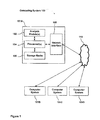
- Fig. 1 depicts an example computing system 100 in accordance with some embodiments.
- the computing system 100 can be an individual computer system 101A or an arrangement of distributed computer systems.
- the computer system 101A includes one or more analysis modules 102 that are configured to perform various tasks according to some embodiments, such as the tasks depicted in Figs. 2 , 7 , and 8 . To perform these various tasks, analysis module 102 executes independently, or in coordination with, one or more processors 104, which is (or are) connected to one or more storage media 106.
- the processor(s) 104 is (or are) also connected to a network interface 108 to allow the computer system 101A to communicate over a data network 110 with one or more additional computer systems and/or computing systems, such as 101B, 101C, and/or 101D (note that computer systems 101B, 101C and/or 101D may or may not share the same architecture as computer system 101A, and may be located in different physical locations, e.g. computer systems 101A and 101B may be on a ship underway on the ocean, while in communication with one or more computer systems such as 101C and/or 101D that are located in one or more data centers on shore, other ships, and/or located in varying countries on different continents).
- additional computer systems and/or computing systems such as 101B, 101C, and/or 101D
- computer systems 101A and 101B may be on a ship underway on the ocean, while in communication with one or more computer systems such as 101C and/or 101D that are located in one or more data centers on shore, other ships, and/or located in varying countries on
- a processor can include a microprocessor, microcontroller, processor module or subsystem, programmable integrated circuit, programmable gate array, or another control or computing device.
- the storage media 106 can be implemented as one or more computer-readable or machine-readable storage media. Note that while in the example embodiment of Fig. 1 storage media 106 is depicted as within computer system 101A, in some embodiments, storage media 106 may be distributed within and/or across multiple internal and/or external enclosures of computing system 101A and/or additional computing systems.
- Storage media 106 may include one or more different forms of memory including semiconductor memory devices such as dynamic or static random access memories (DRAMs or SRAMs), erasable and programmable read-only memories (EPROMs), electrically erasable and programmable read-only memories (EEPROMs) and flash memories; magnetic disks such as fixed, floppy and removable disks; other magnetic media including tape; optical media such as compact disks (CDs) or digital video disks (DVDs); or other types of storage devices.
- semiconductor memory devices such as dynamic or static random access memories (DRAMs or SRAMs), erasable and programmable read-only memories (EPROMs), electrically erasable and programmable read-only memories (EEPROMs) and flash memories
- magnetic disks such as fixed, floppy and removable disks
- other magnetic media including tape optical media such as compact disks (CDs) or digital video disks (DVDs); or other types of storage devices.
- CDs compact disks
- DVDs digital video disks
- Such computer-readable or machine-readable storage medium or media is (are) considered to be part of an article (or article of manufacture).
- An article or article of manufacture can refer to any manufactured single component or multiple components.
- the storage medium or media can be located either in the machine running the machine-readable instructions, or located at a remote site from which machine-readable instructions can be downloaded over a network for execution.
- computing system 100 is only one example of a computing system, and that computing system 100 may have more or fewer components than shown, may combine additional components not depicted in the example embodiment of Figure 1 , and/or computing system 100 may have a different configuration or arrangement of the components depicted in Figure 1 .
- the various components shown in Fig. 1 may be implemented in hardware, software, or a combination of both hardware and software, including one or more signal processing and/or application specific integrated circuits.
- steps in the processing methods described herein may be implemented by running one or more functional modules in information processing apparatus such as general purpose processors or application specific chips, such as ASICs, FPGAs, PLDs, or other appropriate devices.
- information processing apparatus such as general purpose processors or application specific chips, such as ASICs, FPGAs, PLDs, or other appropriate devices.
- the attenuated traveltime integrates the effects of both velocity, v, and Q-effects along the propagation path.
- the attenuated traveltime can be easily computed by reintegrating Q along a traced ray.
- an estimate of attenuated traveltime can be computed for the full wavefield (at all, or substantially all, points in space, x, and time, t ) by running two modelling experiments (either in parallel or sequentially).
- modeling is performed on a second-order in time basis.
- ⁇ is a constant scalar.
- these filters can be applied to the wavefield, P, from the modelling in equation (2) to simulate modelling/compensation of Q -effects.
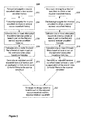
- Figure 2 illustrates a workflow 200 for migration according to some embodiments, and which may be implemented on a computing system such as computing system 100 of Figure 1 .
- an example process of migration uses a workflow as illustrated in Figure 2 .
- the techniques disclosed herein, nor this embodiment in particular, are restricted to this specific migration process; rather, the disclosed embodiments can be applied successfully to any imaging procedure for a subsurface region where compensation for Q -effects or other factors may be desirable, including without limitation the following examples: time-domain visco-acoustic modeling, time-domain visco-acoustic full waveform inversion, simulation of isotropic visco-elastic propagation through mode separation (e.g., using div and/or curl operators), and integration of the effect of S-wave Q- effects and P-wave Q -effects at one or more time steps.
- the techniques can be successfully applied to propagation of any scalar wavefield, not just acoustic wavefields.
- workflow 200 and method 700 compensate for one or more of the following Q -effects including, but not limited to, attenuation, absorption, dissipation, visco-acoustic effects, and other anomalies related to spatial attributes that may be encountered during migration of collected data.
- Figure 2 illustrates a workflow where, initially, a source wavefield of collected data that corresponds to a subsurface region (e.g ., collected seismic data representing a subterranean region being explored for hydrocarbons) is forward propagated to obtain a first source wavefield history (202).
- a source wavefield of collected data that corresponds to a subsurface region (e.g ., collected seismic data representing a subterranean region being explored for hydrocarbons) is forward propagated to obtain a first source wavefield history (202).
- equation 2 as discussed above can be used, though those with skill in the art will recognize that variations of equation 2, as well as alternative methods of obtaining the first source wavefield history, may be successfully performed.
- any acoustic modelling algorithm that steps the wavefield in time including anisotropic acoustic modelling using coupled equations or any recursive integral time extrapolation algorithm, may be successfully employed.
- the source wavefield is again forward propagated to obtain a second source wavefield history (204).
- the second source wavefield history integrates one or more Q -effects.
- equation 3 as discussed above can be used, though those with skill in the art will recognize that variations of equation 3, as well as alternative methods of obtaining the second source wavefield history, may be successfully performed.
- the propagation includes modification of at least a part of the second wavefield through use of a spatial function, as discussed below.
- Method 200 includes estimating one or more attenuated traveltime histories (206) based at least in part on the first and second source wavefield histories, and in some embodiments, equation 4 as discussed above can be used; in alternate embodiments, variations on equation 4 or alternative methods of estimating attenuated traveltimes can be used.
- Calculation of one or more Q -model filters (208) based at least in part on the estimated attenuated traveltime histories is performed in some embodiments, and in some embodiments, equation 5 as discussed above can be used. In alternate embodiments, variations on equation 5, or alternative methods of calculating Q -model filters can be employed.
- Q -model filters are applied using a filter bank of time-invariant absorption filters for compensation of absorption effects on seismic traces.
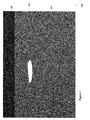
- Figure 3 illustrates a panel 300 representative of a filter bank approach in accordance with some embodiments.
- the horizontal axis 301 represents time
- the vertical axis 302 represents the attenuated traveltime t *.
- a set of one or more time-invariant filters (characterized by t *) is applied to the first source wavefield in time; application of the time-invariant filters forms a panel of filtered wavefields 303.
- An adjusted source wavefield can then be derived by slicing through the panel 300 in accordance with the attenuated traveltime history.
- any other suitable way of applying space- and time-variant non-stationary filters can be used, as those with skill in the art will appreciate.
- an adjusted source wavefield is generated (210) based at least in part on the application of one or more of the Q -model filters to the source wavefield.
- a Q -model filter is applied to the wavefield, P that resulted from the modelling in step 202, ( e.g ., wavefield modelling performed using equation 2) to simulate modelling/compensation of Q -effects.
- steps 212 and 214 With respect to receiver wavefields, backward propagation is used in steps 212 and 214; otherwise, respective steps are analogous for source and receiver wavefields, e.g., step 206 for the source side and step 216 for the receiver side are analogous, and can use similar techniques as discussed above. As such, additional description of steps 212 through 220 will not be described in further detail.
- method 200 can also include the generation of an image (222) based at least in part on the adjusted source and receiver wavefields generated in steps 210 and 220, respectively.
- the image generated is of a subterranean region that includes a region of potential interest for oil and/or gas production, where the wavefields used for imaging correspond at least in part to data acquired as part of a seismic survey.
- the image generated is based at least in part on data acquired as part of a seismic survey of a subterranean region.
- phase and amplitude filters are separately applied on a post-modelling basis to source and/or receiver wavefields before imaging, which enables efficient stabilization of an amplitude amplification filter without altering the phase compensation. Since there is explicit control of both phase and amplitude when filtering wavefields, applications beyond modelling and compensation for absorption effects are possible. For example, if one does not use the phase term in the Q -filters, one can control energy present in an image formed by reverse time migration (“RTM”) (e.g ., consider a salt flank illuminated from above (through a portion of salt whose shape we are unsure about) and from below (through the sediments)).
- RTM reverse time migration
- a RTM image of the reflector just illuminated from below can be generated.
- Another example may be weighting data for inversion, such as full waveform inversion (FWI) (e.g., a velocity model and an uncertainty indicia reflecting confidence or probability of accuracy of the velocity model, can be translated into a Q -model (e.g., a low Q may reflect high confidence).
- FWI full waveform inversion
- Q -model e.g., a low Q may reflect high confidence
- method 200 and variations thereof, enable production of a suite of images using different percentages of an original Q -model with little extra computational cost.
- Figures 4-6 illustrate an example depicting the results of using one embodiment of workflow 200.
- Figures 4-6 illustrate an example of using method 200 with a Q -effect model that is based on data corresponding to a geological area.
- a velocity model with high spatial variability and which corresponds to the geographical area, can be used in accordance with various embodiments disclosed herein.
- prestack synthetic data was generated using a Q -effect finite-difference algorithm, and one hundred and fifty shot gathers were modelled.
- Figure 5 displays the result of applying prestack RTM (500).
- the effect of the Q -anomaly 502 can be seen in a dimming of amplitudes along reflectors underneath the anomaly (e.g., 504-1, 504-2), as well as clear evidence of phase distortions (most notably in the sag on the base reflector 506).
- Figures 7A-7B are flow diagrams illustrating a method of processing and imaging collected data in accordance with some embodiments. Some operations in method 700 may be combined and/or the order of some operations may be changed. Further, some operations in method 700 may be combined with aspects of the example workflows of Figure 2 and/or Figure 8 , and/or the order of some operations in method 700 may be changed to account for incorporation of aspects of the workflow illustrated by Figures 2 and/or 8.
- geologic interpretations, velocity models and/or other interpretation aids may be refined in an iterative fashion; this concept is applicable to methods 200,700, and 800 as discussed herein.
- This can include use of feedback loops executed on an algorithmic basis, such as at a computing device (e.g., computing system 100, Figure 1 ), and/or through manual control by a user who may make determinations regarding whether a given step, action, template, model, or set of curves has become sufficiently accurate for the evaluation of the subsurface three-dimensional geologic formation under consideration.
- the method 700 is performed at a computing device (e.g., computing system 100, Figure 1 ).
- a computing device e.g., computing system 100, Figure 1 .
- method 700 includes receiving a first and a second wavefield comprising collected data that corresponds to a subsurface region.
- the subsurface region is a subterranean region
- the collected data is seismic data, although techniques of method 700 may be applied in other domains such as gravity, magnetics, etc.
- the method 700 also includes propagating (702) a first wavefield to obtain a first wavefield history (e.g., Fig. 2 , step 202,212).
- a first wavefield history e.g., Fig. 2 , step 202,212.
- the first wavefield is a source wavefield, and propagation of the first wavefield to obtain a first wavefield history includes forward propagation (704). In some embodiments, the first wavefield is a receiver wavefield, and propagation of the first wavefield to obtain a first wavefield history includes backward propagation (706). In some embodiments, the first wavefield is ordered based on time as a fast dimension (708).
- the method 700 also includes propagating (710) the first wavefield to obtain a second wavefield history; this wavefield propagation includes integration of one or more Q-effects (e.g., Fig. 2 , step 204, 214).
- the one or more Q -effects are selected from the group consisting of attenuation, absorption, dissipation, and visco-acoustic effects (711).
- the method 700 also includes estimating (712) a first attenuated traveltime history based at least in part on the first and second wavefield histories (e.g., Fig. 2 , step 206, 216).
- the method 700 also includes calculating (714) a first Q -model filter based at least in part on the first estimated attenuated traveltime history (e.g., Fig. 2 , step 208, 218).
- the first Q -model filter is configured to compensate for one or more attributes to be integrated along a wavepath corresponding at least in part to the first wavefield (715); as a non-limiting example, the one or more attributes to be integrated along the wavepath may include uncertainty and/or any other relevant attribute as one with skill in the art will appreciate.
- the method 700 also includes generating (716) a first adjusted wavefield based at least in part on application of the first Q -model filter to the first wavefield (e.g., Fig. 2 , step 210,220).
- method 700 also includes generating (718) an image of the subsurface region based at least in part on the first adjusted wavefield and a second wavefield (e.g., Fig. 2 , step 222). In some embodiments, before generating the image, method 700 also includes scaling the first adjusted wavefield to generate a scaled first adjusted wavefield that is used to generate the image.
- the image generated is of a subterranean region that includes a region of potential interest for oil and/or gas production, where the wavefields used for imaging correspond at least in part to data acquired as part of a seismic survey. In some embodiments, the image generated is based at least in part on data acquired as part of a seismic survey of a subterranean region.
- method 700 also includes propagating a second wavefield to obtain a third wavefield history (e.g., Fig. 2 , step 202, 212); propagating the second wavefield to obtain a fourth wavefield history, wherein the propagation includes integration of one or more Q -effects (e.g., Fig. 2 , step 204, 214); estimating a second attenuated traveltime history based at least in part on the third and fourth wavefield histories (e.g., Fig. 2 , step 206, 216); calculating a second Q -model filter based at least in part on the second estimated attenuated traveltime history (e.g., Fig.
- method 700 also includes generating (722) an image of the subsurface region based at least in part on the first wavefield and the second adjusted wavefield. In alternate embodiments, method 700 also includes generating (724) an image of the subsurface region based at least in part on the first adjusted wavefield and the second adjusted wavefield ( e.g ., Fig. 2 , step 222). In some embodiments, before generating the image, method 700 also includes scaling (725) the first and second adjusted wavefields to generate scaled first and second adjusted wavefields, respectively, that are used to generate the image.
- method 700 also includes scaling the first Q -model filter to generate a scaled Q -model filter; generating a third adjusted wavefield based at least in part on application of the scaled Q -model filter to the first wavefield; and generating an image of the subsurface region based at least in part on the third adjusted wavefield and a second wavefield (726).
- the integral of a given spatial property over the raypath In some embodiments, this can be an integral of a function over the length of the ray or an integral over time along the ray. In some embodiments, the two integrals can be related using the Jacobian, dl / dt , which is the local velocity.
- wave equation evaluation of time integrals for modeling and/or imaging where appropriate, and in such cases, it can be beneficial to evaluate integrals similar to the ray based integrals above.
- the wave paths in U 2 will be almost identical to the wave paths in U as long as the amplitude factor is sufficiently smooth.
- the amplitude of any particular portion of the wavefield will be approximately the original unmodified field multiplied by the product of the amplitude factors at the location of the wavefield at each time step; in some embodiments, this can be calculated, estimated, and/or derived from equation 13.
- the product will be the product of A ( x' ) for the locations x' that the wave passed through at each time step. If there are multiple paths, then the new field will be a sum of differently weighted waves.
- a x ⁇ e - f x ⁇ ⁇ ⁇ ⁇ t which in some embodiments results in a product expressed and/or characterized from group of equations 15:
- one may calculate, estimate, and/or derive according to one or more of the following group of expressions 16: ln U x t U 2 x t ⁇ or ln ⁇ U x t ⁇ ⁇ U 2 x t ⁇ ⁇ or ln ⁇ U x t ⁇ U 2 x t ⁇ ⁇ U 2 x t ⁇ U 2 x t ⁇ where the expression actually employed denotes some local averaging operation, an expectation estimation, and/or time and space averaging.
- path-length integrals for approximation so as to obtain a wave based approximation to any integral of the form used in ray based modeling.
- the following expression 17 may be used successfully:
- a x ⁇ e - f x ⁇ ⁇ v x ⁇ ⁇ ⁇ ⁇ t ⁇ ⁇ yields ⁇ ln U x t U 2 x t ⁇ ⁇ 0 l ⁇ f x ⁇ l ⁇ ⁇ d ⁇ l ⁇
- one-way spatial extrapolation can be used, including the following non-limiting examples, downward extrapolation in depth, tilted coordinate frames, or as those with skill in the art will recognize, any suitable, generalized coordinate system.
- Figure 8 is a flow diagram illustrating a method 800 of processing and imaging collected data in accordance with some embodiments. Some operations in method 800 may be combined and/or the order of some operations may be changed. Further, some operations in method 800 may be combined with aspects of the example workflows of Figure 2 and/or Figure 7 , and/or the order of some operations in method 800 may be changed to account for incorporation of aspects of the workflow illustrated by Figures 2 and/or 7.
- the method 800 is performed at a computing device (e.g., computing system 100, Figure 1 ).
- a computing device e.g., computing system 100, Figure 1 .
- method 800 includes receiving a first and a second wavefield comprising collected data that corresponds to a subsurface region.
- the subsurface region is a subterranean region
- the collected data is seismic data, although techniques of method 800 may be applied in other domains such as gravity, magnetics, etc.
- the method 800 also includes propagating (802) a first wavefield to obtain a first wavefield history (e.g., Fig. 2 , step 202,212).
- a first wavefield history e.g., Fig. 2 , step 202,212.
- the method 800 also includes propagating (804) a second wavefield to obtain a second wavefield history, wherein the propagation includes modification of at least a part of the second wavefield through use of a spatial function (such as a spatial variable function), wherein the propagation of the first and second wavefields use substantially the same starting conditions (e.g ., such as initial conditions to the wave equation, including, but not limited to the examples of source functions, receiver wavefields, receiver data boundary values, etc.) (e.g., Fig. 2 , step 204, 214).
- a spatial function such as a spatial variable function
- the use of the spatial function during propagation of the second wavefield includes multiplying by the spatial function to obtain the second wavefield history (806).
- the spatial function is configured to generate an approximation to an integral of a selected function over a wavepath corresponding at least in part to the first wavefield (808); and in some embodiments, a wavefield combination is also used during the approximation of the integral of the selected function.
- the generation of the approximation is based at least in part on computing a ratio of the first and second wavefields (810).
- the computation of the ratio is performed by estimating a ratio in a stable manner, i.e., so as to avoid dividing by zero with respect to a wavefield being adjusted by the calculation.
- the integration is over space (e.g., the integration domain is space) (812).
- the integration is over time (e.g., the integration domain is time) (814).
- the approximation of the integral of the selected function over the wavepath 808 is selected from the group consisting of: integration of a given spatial property of a raypath; integration of a function over the length of the raypath; integration of time along the raypath; integration of effective Q along the raypath; integration of time perturbation along the raypath; integration of one or more uncertainty metrics along the raypath; integration of path-length; and integration for spatial extrapolation for solving one or more wave equations.
- the modification of the part of the second wavefield includes changing the amplitude of the second wavefield (816).
- those with skill in the art could perform one or more aspects of methods 700 and/or 200 in conjunction with or in combination with the results of method 800, including, but not limited to, estimating one or more attenuated traveltime histories, calculating one or more Q -model filters, generating one or more adjusted wavefield histories based at least in part on the application of the one or more Q -model filters, etc.
- the steps in the processing methods described above may be implemented by running one or more functional modules in information processing apparatus such as general purpose processors or application specific chips, such as ASICs, FPGAs, PLDs, or other appropriate devices. These modules, combinations of these modules, and/or their combination with general hardware are all included within the scope of protection of the invention.
Landscapes
- Engineering & Computer Science (AREA)
- Remote Sensing (AREA)
- Physics & Mathematics (AREA)
- Life Sciences & Earth Sciences (AREA)
- Acoustics & Sound (AREA)
- Environmental & Geological Engineering (AREA)
- Geology (AREA)
- General Life Sciences & Earth Sciences (AREA)
- General Physics & Mathematics (AREA)
- Geophysics (AREA)
- Image Processing (AREA)
- Geophysics And Detection Of Objects (AREA)
Applications Claiming Priority (2)
| Application Number | Priority Date | Filing Date | Title |
|---|---|---|---|
| US13/286,574 US9201153B2 (en) | 2011-11-01 | 2011-11-01 | Methods and devices for transformation of collected data for improved visualization capability |
| EP12845174.7A EP2773984A4 (de) | 2011-11-01 | 2012-11-01 | Verfahren und vorrichtungen zur umwandlung gesammelter daten für verbesserte visualisierungsfähigkeit |
Related Parent Applications (1)
| Application Number | Title | Priority Date | Filing Date |
|---|---|---|---|
| EP12845174.7A Division EP2773984A4 (de) | 2011-11-01 | 2012-11-01 | Verfahren und vorrichtungen zur umwandlung gesammelter daten für verbesserte visualisierungsfähigkeit |
Publications (2)
| Publication Number | Publication Date |
|---|---|
| EP2863243A2 true EP2863243A2 (de) | 2015-04-22 |
| EP2863243A3 EP2863243A3 (de) | 2016-01-06 |
Family
ID=48172313
Family Applications (2)
| Application Number | Title | Priority Date | Filing Date |
|---|---|---|---|
| EP12845174.7A Withdrawn EP2773984A4 (de) | 2011-11-01 | 2012-11-01 | Verfahren und vorrichtungen zur umwandlung gesammelter daten für verbesserte visualisierungsfähigkeit |
| EP14198387.4A Withdrawn EP2863243A3 (de) | 2011-11-01 | 2012-11-01 | Verfahren und Vorrichtungen zur Umwandlung gesammelter seismischer Daten für verbesserte Visualisierungsfähigkeit |
Family Applications Before (1)
| Application Number | Title | Priority Date | Filing Date |
|---|---|---|---|
| EP12845174.7A Withdrawn EP2773984A4 (de) | 2011-11-01 | 2012-11-01 | Verfahren und vorrichtungen zur umwandlung gesammelter daten für verbesserte visualisierungsfähigkeit |
Country Status (3)
| Country | Link |
|---|---|
| US (2) | US9201153B2 (de) |
| EP (2) | EP2773984A4 (de) |
| WO (1) | WO2013067107A1 (de) |
Cited By (1)
| Publication number | Priority date | Publication date | Assignee | Title |
|---|---|---|---|---|
| CN114460646A (zh) * | 2022-04-13 | 2022-05-10 | 山东省科学院海洋仪器仪表研究所 | 一种基于波场激发近似的反射波旅行时反演方法 |
Families Citing this family (20)
| Publication number | Priority date | Publication date | Assignee | Title |
|---|---|---|---|---|
| US9201153B2 (en) * | 2011-11-01 | 2015-12-01 | Westerngeco L.L.C. | Methods and devices for transformation of collected data for improved visualization capability |
| US20130311149A1 (en) * | 2012-05-17 | 2013-11-21 | Yaxun Tang | Tomographically Enhanced Full Wavefield Inversion |
| CN103424777B (zh) * | 2013-07-01 | 2016-06-08 | 中国科学院地质与地球物理研究所 | 一种提高地震成像分辨率的方法 |
| US10379245B2 (en) * | 2013-07-03 | 2019-08-13 | Pgs Geophysical As | Method and system for efficient extrapolation of a combined source-and-receiver wavefield |
| WO2015171614A1 (en) | 2014-05-05 | 2015-11-12 | Vicarious Surgical Inc. | Virtual reality surgical device |
| MX362753B (es) * | 2014-06-17 | 2019-02-07 | Exxonmobil Upstream Res Co | Inversion rapida de campo de ondas completo viscoacustico y viscoelastico. |
| US10670396B2 (en) * | 2014-09-08 | 2020-06-02 | Sikorsky Aircraft Corporation | Multi-sensor target location registration |
| WO2016075550A1 (en) * | 2014-11-14 | 2016-05-19 | Cgg Services Sa | Device and method for weighted sparse inversion for seismic processing |
| EP3245542B1 (de) * | 2015-01-13 | 2021-11-03 | BP Corporation North America Inc. | Stack-ghost-unterdrückung |
| EP3076205B1 (de) * | 2015-03-31 | 2023-06-14 | CGG Services SAS | Verfahren zur vermessungsdatenverarbeitung zur kompensation visko-akustischer effekte in reverse-time-migration mit geneigter transversaler isotropie |
| US9784867B2 (en) * | 2015-04-01 | 2017-10-10 | Schlumberger Technology Corporation | Seismic data processing |
| WO2017100746A1 (en) * | 2015-12-11 | 2017-06-15 | Ion Geophysical Corporation | System and method for reconstructed wavefield inversion |
| WO2018119005A1 (en) | 2016-12-20 | 2018-06-28 | Ion Geophysical Corporation | System and method for reconstructed wavefield imaging |
| WO2018148394A1 (en) | 2017-02-09 | 2018-08-16 | Vicarious Surgical Inc. | Virtual reality surgical tools system |
| US10345466B2 (en) * | 2017-07-25 | 2019-07-09 | Advanced Geophysical Technology Inc. | Memory efficient Q-RTM computer method and apparatus for imaging seismic data |
| EP3681368A4 (de) | 2017-09-14 | 2021-06-23 | Vicarious Surgical Inc. | Chirurgisches kamerasystem mit virtueller realität |
| US11340366B2 (en) * | 2018-10-17 | 2022-05-24 | Exxonmobil Upstream Research Company | Accurate velocity model estimation and imaging in the presence of localized attenuation (Q) anomalies |
| CN110579805B (zh) * | 2019-10-17 | 2021-03-12 | 西南石油大学 | 一种基于自适应增益限反q滤波的地震资料处理方法 |
| US20230140168A1 (en) * | 2021-10-29 | 2023-05-04 | Chevron U.S.A. Inc. | System and method for compensating for attenuation of seismic energy |
| US11754733B2 (en) * | 2021-10-29 | 2023-09-12 | Chevron U.S.A. Inc. | System and method for generating a seismic attenuation model |
Family Cites Families (11)
| Publication number | Priority date | Publication date | Assignee | Title |
|---|---|---|---|---|
| US5920828A (en) | 1997-06-02 | 1999-07-06 | Baker Hughes Incorporated | Quality control seismic data processing system |
| US6931324B2 (en) | 2003-10-16 | 2005-08-16 | Rdspi, L.P. | Method for determining formation quality factor from seismic data |
| WO2006025823A1 (en) | 2004-08-27 | 2006-03-09 | Westerngeco, L.L.C. | Method for correcting input seismic traces from dissipative effects |
| US7477992B2 (en) | 2005-02-18 | 2009-01-13 | Exxonmobil Upstream Research Company | Method for combining seismic data sets |
| US7376517B2 (en) * | 2005-05-13 | 2008-05-20 | Chevron U.S.A. Inc. | Method for estimation of interval seismic quality factor |
| US7397728B2 (en) | 2005-08-26 | 2008-07-08 | Westerngeco L.L.C. | Method for processing a record of seismic traces |
| US7555389B2 (en) * | 2007-06-15 | 2009-06-30 | Westerngeco L.L.C. | Creating an Absorption Parameter Model |
| US9582931B2 (en) | 2010-02-26 | 2017-02-28 | Chevron U.S.A. Inc. | Surface smoothing within an earth model of a geological volume of interest |
| US8385151B2 (en) * | 2010-06-24 | 2013-02-26 | Chevron U.S.A. Inc. | Reverse time migration with absorbing and random boundaries |
| US8773951B2 (en) * | 2011-03-18 | 2014-07-08 | Chevron U.S.A. Inc. | System and method for seismic imaging with reduced computational cost |
| US9201153B2 (en) * | 2011-11-01 | 2015-12-01 | Westerngeco L.L.C. | Methods and devices for transformation of collected data for improved visualization capability |
-
2011
- 2011-11-01 US US13/286,574 patent/US9201153B2/en not_active Expired - Fee Related
-
2012
- 2012-11-01 EP EP12845174.7A patent/EP2773984A4/de not_active Withdrawn
- 2012-11-01 WO PCT/US2012/062944 patent/WO2013067107A1/en not_active Ceased
- 2012-11-01 EP EP14198387.4A patent/EP2863243A3/de not_active Withdrawn
-
2015
- 2015-10-30 US US14/929,218 patent/US20160124103A1/en not_active Abandoned
Non-Patent Citations (1)
| Title |
|---|
| None |
Cited By (2)
| Publication number | Priority date | Publication date | Assignee | Title |
|---|---|---|---|---|
| CN114460646A (zh) * | 2022-04-13 | 2022-05-10 | 山东省科学院海洋仪器仪表研究所 | 一种基于波场激发近似的反射波旅行时反演方法 |
| CN114460646B (zh) * | 2022-04-13 | 2022-06-28 | 山东省科学院海洋仪器仪表研究所 | 一种基于波场激发近似的反射波旅行时反演方法 |
Also Published As
| Publication number | Publication date |
|---|---|
| WO2013067107A1 (en) | 2013-05-10 |
| EP2773984A4 (de) | 2016-01-06 |
| US20130107665A1 (en) | 2013-05-02 |
| EP2773984A1 (de) | 2014-09-10 |
| US20160124103A1 (en) | 2016-05-05 |
| EP2863243A3 (de) | 2016-01-06 |
| US9201153B2 (en) | 2015-12-01 |
Similar Documents
| Publication | Publication Date | Title |
|---|---|---|
| EP2863243A2 (de) | Verfahren und Vorrichtungen zur Umwandlung gesammelter seismischer Daten für verbesserte Visualisierungsfähigkeit | |
| Shin et al. | A comparison between the behavior of objective functions for waveform inversion in the frequency and Laplace domains | |
| Vigh et al. | 3D prestack plane-wave, full-waveform inversion | |
| EP3073296B1 (de) | Vollwellenforminversionsverfahren zur verarbeitung von seismischen daten mit amplitudenerhaltender umkehrzeitmigration | |
| US8352190B2 (en) | Method for analyzing multiple geophysical data sets | |
| Zhang et al. | Robust source-independent elastic full-waveform inversion in the time domain | |
| EP3259620B1 (de) | Mehrstufiges verfahren zur vollwellenfeldinversion zur erzeugung eines multiple-freien datensatzes | |
| CN111505714B (zh) | 基于岩石物理约束的弹性波直接包络反演方法 | |
| US11635540B2 (en) | Methods and devices performing adaptive quadratic Wasserstein full-waveform inversion | |
| Jia et al. | Subsalt Marchenko imaging: a Gulf of Mexico example | |
| Biondi et al. | Target-oriented elastic full-waveform inversion through acoustic extended image-space redatuming | |
| Raknes et al. | Challenges and solutions for performing 3D time-domain elastic full-waveform inversion | |
| Biondi | Target-oriented elastic full-waveform inversion | |
| US12379514B2 (en) | System and method for elastic full waveform inversion and imaging | |
| Tang et al. | Target-oriented wavefield tomography using synthesized Born data | |
| Sarajaervi et al. | Computation of ray-Born seismograms using isochrons | |
| Zhong et al. | Time-domain acoustic full-waveform inversion based on dual-sensor seismic acquisition system | |
| Park et al. | Damped wave-equation-based first-arrival traveltime tomography using the embedded boundary method | |
| US20250251521A1 (en) | System and method for generating modeled data based on wavefield propagation with time-variant subsurface property | |
| Hwang et al. | Acoustic full-waveform inversion to match far-offset reflections with pseudo-horizontal particle acceleration data | |
| Plessix et al. | Frequency-domain finite-difference migration with only few frequencies? | |
| Bevc et al. | 3-D tomographic updating with automatic volume-based picking | |
| Lu et al. | Full Waveform Inversion Based on Modified Quasi‐Newton Equation Quasi‐Newton Equation | |
| Hulex | Stabilizing 2nd Cartesian Converted-Back Acoustic Pseudodepth LSRTM Wavefield Via Controlled FDTD Approach | |
| Chi et al. | Source-independent amplitude-semblance full-waveform inversion using a hybrid time-and frequency-domain approach |
Legal Events
| Date | Code | Title | Description |
|---|---|---|---|
| PUAI | Public reference made under article 153(3) epc to a published international application that has entered the european phase |
Free format text: ORIGINAL CODE: 0009012 |
|
| 17P | Request for examination filed |
Effective date: 20141216 |
|
| AC | Divisional application: reference to earlier application |
Ref document number: 2773984 Country of ref document: EP Kind code of ref document: P |
|
| AK | Designated contracting states |
Kind code of ref document: A2 Designated state(s): AL AT BE BG CH CY CZ DE DK EE ES FI FR GB GR HR HU IE IS IT LI LT LU LV MC MK MT NL NO PL PT RO RS SE SI SK SM TR |
|
| PUAL | Search report despatched |
Free format text: ORIGINAL CODE: 0009013 |
|
| AK | Designated contracting states |
Kind code of ref document: A3 Designated state(s): AL AT BE BG CH CY CZ DE DK EE ES FI FR GB GR HR HU IE IS IT LI LT LU LV MC MK MT NL NO PL PT RO RS SE SI SK SM TR |
|
| RIC1 | Information provided on ipc code assigned before grant |
Ipc: G01V 1/34 20060101ALN20151130BHEP Ipc: G01V 1/30 20060101AFI20151130BHEP Ipc: G06F 17/10 20060101ALN20151130BHEP Ipc: G01V 1/36 20060101ALI20151130BHEP Ipc: G06F 19/00 20110101ALN20151130BHEP |
|
| 17Q | First examination report despatched |
Effective date: 20160229 |
|
| STAA | Information on the status of an ep patent application or granted ep patent |
Free format text: STATUS: THE APPLICATION IS DEEMED TO BE WITHDRAWN |
|
| 18D | Application deemed to be withdrawn |
Effective date: 20170822 |