EP2863199A1 - Duplex pressure transducers - Google Patents
Duplex pressure transducers Download PDFInfo
- Publication number
- EP2863199A1 EP2863199A1 EP20140189021 EP14189021A EP2863199A1 EP 2863199 A1 EP2863199 A1 EP 2863199A1 EP 20140189021 EP20140189021 EP 20140189021 EP 14189021 A EP14189021 A EP 14189021A EP 2863199 A1 EP2863199 A1 EP 2863199A1
- Authority
- EP
- European Patent Office
- Prior art keywords
- transducer
- pressure
- base
- receptacles
- recited
- Prior art date
- Legal status (The legal status is an assumption and is not a legal conclusion. Google has not performed a legal analysis and makes no representation as to the accuracy of the status listed.)
- Granted
Links
Images

Classifications
-
- G—PHYSICS
- G01—MEASURING; TESTING
- G01L—MEASURING FORCE, STRESS, TORQUE, WORK, MECHANICAL POWER, MECHANICAL EFFICIENCY, OR FLUID PRESSURE
- G01L13/00—Devices or apparatus for measuring differences of two or more fluid pressure values
- G01L13/02—Devices or apparatus for measuring differences of two or more fluid pressure values using elastically-deformable members or pistons as sensing elements
- G01L13/028—Devices or apparatus for measuring differences of two or more fluid pressure values using elastically-deformable members or pistons as sensing elements using capsules
-
- G—PHYSICS
- G01—MEASURING; TESTING
- G01L—MEASURING FORCE, STRESS, TORQUE, WORK, MECHANICAL POWER, MECHANICAL EFFICIENCY, OR FLUID PRESSURE
- G01L13/00—Devices or apparatus for measuring differences of two or more fluid pressure values
- G01L13/04—Devices or apparatus for measuring differences of two or more fluid pressure values using floats or liquids as sensing elements
-
- G—PHYSICS
- G01—MEASURING; TESTING
- G01D—MEASURING NOT SPECIALLY ADAPTED FOR A SPECIFIC VARIABLE; ARRANGEMENTS FOR MEASURING TWO OR MORE VARIABLES NOT COVERED IN A SINGLE OTHER SUBCLASS; TARIFF METERING APPARATUS; MEASURING OR TESTING NOT OTHERWISE PROVIDED FOR
- G01D11/00—Component parts of measuring arrangements not specially adapted for a specific variable
- G01D11/24—Housings ; Casings for instruments
- G01D11/245—Housings for sensors
-
- G—PHYSICS
- G01—MEASURING; TESTING
- G01L—MEASURING FORCE, STRESS, TORQUE, WORK, MECHANICAL POWER, MECHANICAL EFFICIENCY, OR FLUID PRESSURE
- G01L19/00—Details of, or accessories for, apparatus for measuring steady or quasi-steady pressure of a fluent medium insofar as such details or accessories are not special to particular types of pressure gauges
- G01L19/0007—Fluidic connecting means
- G01L19/0038—Fluidic connecting means being part of the housing
-
- G—PHYSICS
- G01—MEASURING; TESTING
- G01L—MEASURING FORCE, STRESS, TORQUE, WORK, MECHANICAL POWER, MECHANICAL EFFICIENCY, OR FLUID PRESSURE
- G01L15/00—Devices or apparatus for measuring two or more fluid pressure values simultaneously
Definitions
- the present disclosure relates to differential pressure transducers, and more particularly to high temperature duplex pressure transducers.
- Differential pressure measurements can be accomplished by a differential pressure transducer which provides an output that is the difference between two pressures.
- the output is truly indicative of monitored pressure, e.g. relative to a vacuum.
- a duplex differential pressure transducer traditionally has two separate absolute pressure capsules to measure differential pressure across a medium such as, for example, an oil filter. The monitored absolute pressure outputs from each pressure capsule are compared to determine the pressure difference between an inlet side and an outlet side of the oil filter.
- duplex pressure transducers Generally, traditional duplex pressure transducers must meet certain accuracy and size requirements. Larger pressure capsules increase pressure measurement accuracy. But, on the other hand, duplex pressure transducers are generally found in confined areas where space and clearance are critical, making dimension requirements and size high priority considerations. Duplex pressure transducers generally house the pressure capsules in a side-by-side horizontal arrangement.
- duplex pressure transducers that allow for improved accuracy while still conforming to envelope size restrictions.
- duplex pressure transducers that are easy to make and use. The present disclosure provides a solution for these problems.
- a transducer baseplate includes a base with a protrusion extending from the base along a longitudinal axis, a pair of opposed transducer receptacles defined within the protrusion, and a pair of respective pressure plena.
- the pressure plena are separated by a plenum wall, one plenum in fluid communication with each receptacle, respectively, and each plenum being in fluid connection with an area external to the protrusion through a respective pressure line.
- the pressure lines provide a direct fluid path to their respective receptacles.
- the receptacles each have a cross-sectional shape and the base has a cross-sectional perimeter in a plane perpendicular to the longitudinal axis.
- the combined cross-sectional shapes of the receptacles are too large to fit within the cross-sectional perimeter of the base.
- the pressure lines can also each have a cross-sectional shape.
- the combined cross-sectional shapes of one pressure line and of one receptacle are too large to fit within the cross-sectional perimeter of the base.
- the receptacles can have circular cross-sections and each can have a receptacle diameter in a plane aligned with the longitudinal axis.
- the base and pressure lines can also have circular cross-sections.
- the base can have a base diameter in a plane perpendicular to the longitudinal axis where the combined receptacle diameters are greater than the base diameter.
- the receptacles can be configured to each receive a separate high temperature pressure capsule.
- the protrusion can also include an end surface configured to secure circuitry.
- the transducer baseplate can also include a mounting flange below the base with respect to the longitudinal axis.
- the pressure lines can define a channel through the mounting flange, through the base, and through the protrusion to provide a direct fluid path to their respective receptacles.
- the mounting flange can have sealing sockets defined proximate to respective first ends of the pressure lines. The sealing sockets can be configured to receive seals.
- the transducer baseplate is configured to withstand temperatures from -55 to 205 degrees Celsius (218 to 478 degrees Kelvin), and pressures from 2 to 800 psi (13.9 kPa to 5.52 MPa) while still maintaining less than ⁇ 1% error.
- a duplex pressure transducer includes a transducer baseplate as described above, a separate high temperature pressure capsule secured in each receptacle, circuitry, and a transducer housing.
- the circuitry is operatively connected to an end surface of the protrusion each in electronic communication with a separate high temperature pressure capsules.
- the transducer housing is sealed over at least the transducer receptacles, high temperature pressure capsules, and circuitry.
- the circuitry can include a pair of opposing circuit boards. The circuit boards each can be configured to receive pressure readings from their respective separate high temperature pressure capsules.
- the high temperature pressure capsules can be spaced away from the transducer housing such that there is clearance for at least one electrical cable each between the high temperature pressure capsules and the transducer housing.
- the transducer housing can be affixed to the baseplate by weld joints located on the base, and can include a port configured to receive electrical connectors.
- the transducer housing and weld joints can be configured to withstand burst pressures of up to 2540 psi (17.51 MPa).
- transducer baseplate, high temperature pressure capsules, circuitry and transducer housing can be configured to withstand temperatures from -55 to 205 degrees Celsius (218 to 478 degrees Kelvin) and pressures from 2 to 800 psi (13.9 kPa to 5.52 MPa) while still maintaining less than ⁇ 1% error.
- a perspective view of an exemplary embodiment of a transducer baseplate constructed in accordance with the present disclosure is shown in Fig. 1 and is designated generally by reference character 100.
- Other embodiments of a transducer baseplate constructed in accordance with the present disclosure, or aspects thereof, are provided in Figs. 2-4 , as will be described.
- a transducer baseplate 100 includes a base 102, a protrusion 104 extending from base 102 along a longitudinal axis A, a pair of opposed transducer receptacles 106 defined within protrusion 104, and pressure plena 108 associated with each receptacle 106.
- Protrusion 104 has an end surface 114.
- Transducer baseplate 100 also includes a mounting flange 118. Mounting flange 118 is below base 102 with respect to longitudinal axis A, as oriented in Fig. 1 .
- Mounting flange 118 has sealing sockets 120 defined proximate to respective first ends 113 of pressure lines 112. Sealing sockets 120 are configured to receive seals (not shown). A variety of seals can be used, such as, o-ring seals.
- Transducer baseplate 100 is configured to withstand temperatures from -55 to 205 degrees Celsius (218 to 478 degrees Kelvin), and pressures from 2 to 800 psi (13.9 kPa to 5.52 MPa) while still maintaining less than ⁇ 1% error. It can be appreciated that the temperature and pressure ranges listed above are working temperatures and pressures for maintaining less than ⁇ 1% error and that baseplate 100 can be configured to withstand higher temperatures and pressures.
- each receptacle 106 is configured to receive a separate high temperature pressure capsule 115.
- Pressure lines 112 each define a channel through mounting flange 118, through base 102, and through protrusion 104 to provide a direct fluid path to their respective receptacles 106.
- Receptacles 106 each have a cross-sectional shape B, and base 102 has a cross-sectional perimeter C, in a plane perpendicular to the longitudinal axis A. Combined cross-sectional shapes B are too large to fit non-overlappingly within cross-sectional perimeter C of base 102.
- each receptacle 106 has a receptacle diameter E in a plane parallel to longitudinal axis A.
- Base 102 has a base diameter F in a plane perpendicular to the longitudinal axis A. The combined receptacle diameters E are greater than base diameter F.
- high temperature pressure capsules 115 do not fit inside the transducer housing (122) in a side by side arrangement, i.e. where each receptacle diameter E is aligned perpendicular to longitudinal axis A. Instead, a vertical configuration of high temperature pressure capsules 115, i.e. with each receptacle diameter E aligned parallel to longitudinal axis A, is used to create a transducer that accommodates larger capsules than traditional configurations, therein making the transducer more accurate. Further, it can be appreciated that while shown substantially in cylindrical shapes, high temperature pressure capsules 115 and receptacles 106, can be of any suitable shape.
- Duplex pressure transducer 200 includes a transducer baseplate 100 as described above, a separate high temperature pressure capsule 115 secured in each receptacle 106, circuitry 116, and a transducer housing 122.
- Circuitry 116 shown as a pair of opposing circuit boards, are operatively connected to end surface 114 of protrusion 104 each in electronic communication with separate high temperature pressure capsules 115.
- Each circuit board 116 is configured to receive pressure readings from its respective separate high temperature pressure capsule 115.
- the high temperature pressure capsules 115 are spaced away from transducer housing 122 such that there is clearance for at least one electrical cable each, shown schematically, between high temperature pressure capsules 115 and transducer housing 122.
- transducer housing 122 is hermetically sealed over at least transducer receptacles 106, high temperature pressure capsules 115, and circuit boards 116.
- Transducer housing 122 is affixed to the baseplate 100 by weld joints 124 located on base 102. Further, transducer housing 122 includes a port 126 configured to receive electrical connectors 128, shown schematically. It can be appreciated that while one port 126 is shown, any suitable number of ports can be defined in the transducer housing 122 for a given application.
- the thickness and material of transducer housing 122 and weld joints 124 is configured to withstand burst pressures of up to 2540 psi (17.51 MPa).
- duplex pressure transducer 200 uses separate high temperature pressure capsules 115 to measure differential pressure across a medium, such as an oil filter.
- Duplex pressure transducer 200 is designed to have less than ⁇ 1% error over the operating ranges of -55 to 205 degrees Celsius (218 to 478 degrees Kelvin) and 2 to 800 psi (13.9 kPa to 5.52 MPa).
- the size of the high temperature pressure capsules 115 may need to increase.
- duplex pressure transducer 200 is configured to allow for a larger capsule, without sacrificing size or pressure and temperature capacity.
- the vertical transducer baseplate 100 configuration for the high temperature pressure capsules 115, as described above, allows for increased accuracy by tolerating a larger capsule, without sacrificing duplex pressure transducer size, or pressure and temperature capacity.
- duplex transducer baseplate and duplex pressure transducer with superior properties including increased accuracy, small size and high pressure and temperature tolerance. While the apparatus and methods of the subject disclosure have been shown and described with reference to preferred embodiments, those skilled in the art will readily appreciate that changes and/or modifications may be made thereto without departing from the scope of the subject disclosure.
Landscapes
- Physics & Mathematics (AREA)
- General Physics & Mathematics (AREA)
- Measuring Fluid Pressure (AREA)
Abstract
Description
- The present disclosure relates to differential pressure transducers, and more particularly to high temperature duplex pressure transducers.
- Differential pressure measurements can be accomplished by a differential pressure transducer which provides an output that is the difference between two pressures. In the case of the absolute pressure transducer, the output is truly indicative of monitored pressure, e.g. relative to a vacuum. A duplex differential pressure transducer traditionally has two separate absolute pressure capsules to measure differential pressure across a medium such as, for example, an oil filter. The monitored absolute pressure outputs from each pressure capsule are compared to determine the pressure difference between an inlet side and an outlet side of the oil filter.
- Generally, traditional duplex pressure transducers must meet certain accuracy and size requirements. Larger pressure capsules increase pressure measurement accuracy. But, on the other hand, duplex pressure transducers are generally found in confined areas where space and clearance are critical, making dimension requirements and size high priority considerations. Duplex pressure transducers generally house the pressure capsules in a side-by-side horizontal arrangement.
- Such conventional methods and systems have generally been considered satisfactory for their intended purpose. However, there is still a need in the art for duplex pressure transducers that allow for improved accuracy while still conforming to envelope size restrictions. There also remains a need in the art for such duplex pressure transducers that are easy to make and use. The present disclosure provides a solution for these problems.
- A transducer baseplate includes a base with a protrusion extending from the base along a longitudinal axis, a pair of opposed transducer receptacles defined within the protrusion, and a pair of respective pressure plena. The pressure plena are separated by a plenum wall, one plenum in fluid communication with each receptacle, respectively, and each plenum being in fluid connection with an area external to the protrusion through a respective pressure line. The pressure lines provide a direct fluid path to their respective receptacles.
- In certain embodiments, the receptacles each have a cross-sectional shape and the base has a cross-sectional perimeter in a plane perpendicular to the longitudinal axis. The combined cross-sectional shapes of the receptacles are too large to fit within the cross-sectional perimeter of the base. The pressure lines can also each have a cross-sectional shape. The combined cross-sectional shapes of one pressure line and of one receptacle are too large to fit within the cross-sectional perimeter of the base.
- In accordance with certain embodiments, the receptacles can have circular cross-sections and each can have a receptacle diameter in a plane aligned with the longitudinal axis. The base and pressure lines can also have circular cross-sections. The base can have a base diameter in a plane perpendicular to the longitudinal axis where the combined receptacle diameters are greater than the base diameter.
- It is contemplated that the receptacles can be configured to each receive a separate high temperature pressure capsule. In addition, the protrusion can also include an end surface configured to secure circuitry. The transducer baseplate can also include a mounting flange below the base with respect to the longitudinal axis. The pressure lines can define a channel through the mounting flange, through the base, and through the protrusion to provide a direct fluid path to their respective receptacles. The mounting flange can have sealing sockets defined proximate to respective first ends of the pressure lines. The sealing sockets can be configured to receive seals. Further, the transducer baseplate is configured to withstand temperatures from -55 to 205 degrees Celsius (218 to 478 degrees Kelvin), and pressures from 2 to 800 psi (13.9 kPa to 5.52 MPa) while still maintaining less than ± 1% error.
- A duplex pressure transducer includes a transducer baseplate as described above, a separate high temperature pressure capsule secured in each receptacle, circuitry, and a transducer housing. The circuitry is operatively connected to an end surface of the protrusion each in electronic communication with a separate high temperature pressure capsules. The transducer housing is sealed over at least the transducer receptacles, high temperature pressure capsules, and circuitry. The circuitry can include a pair of opposing circuit boards. The circuit boards each can be configured to receive pressure readings from their respective separate high temperature pressure capsules.
- In accordance with certain embodiments, the high temperature pressure capsules can be spaced away from the transducer housing such that there is clearance for at least one electrical cable each between the high temperature pressure capsules and the transducer housing. The transducer housing can be affixed to the baseplate by weld joints located on the base, and can include a port configured to receive electrical connectors. The transducer housing and weld joints can be configured to withstand burst pressures of up to 2540 psi (17.51 MPa).
- It is contemplated that the transducer baseplate, high temperature pressure capsules, circuitry and transducer housing can be configured to withstand temperatures from -55 to 205 degrees Celsius (218 to 478 degrees Kelvin) and pressures from 2 to 800 psi (13.9 kPa to 5.52 MPa) while still maintaining less than ± 1% error.
- These and other features of the systems and methods of the subject disclosure will become more readily apparent to those skilled in the art from the following detailed description of the preferred embodiments taken in conjunction with the drawings.
- So that those skilled in the art to which the subject disclosure appertains will readily understand how to make and use the devices and methods of the subject disclosure without undue experimentation, preferred embodiments thereof will be described in detail herein below by way of example only and with reference to certain figures, wherein:
-
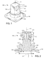
Fig. 1 is a perspective view of an exemplary embodiment of a transducer baseplate constructed in accordance with the present disclosure, showing a mounting flange, a base, a protrusion and receptacles; -
Fig. 2 is a cross-sectional side-elevation view of the transducer baseplate ofFig. 1 , showing the receptacles with high temperature pressure capsules, respective pressure plena, pressure lines and sealing sockets; -
Fig. 3 is a perspective view of an exemplary embodiment of a duplex pressure transducer constructed in accordance with the present disclosure, showing a transducer housing partially sealed over the transducer baseplate ofFig. 1 ; and -
Fig. 4 is a cross-sectional perspective view of the duplex pressure transducer ofFig. 3 , showing the transducer baseplate ofFig. 1 with high temperature pressure capsules and circuit boards. - Reference will now be made to the drawings wherein like reference numerals identify similar structural features or aspects of the subject disclosure. For purposes of explanation and illustration, and not limitation, a perspective view of an exemplary embodiment of a transducer baseplate constructed in accordance with the present disclosure is shown in
Fig. 1 and is designated generally byreference character 100. Other embodiments of a transducer baseplate constructed in accordance with the present disclosure, or aspects thereof, are provided inFigs. 2-4 , as will be described. - In reference to
Figs. 1 and 2 , atransducer baseplate 100 includes abase 102, aprotrusion 104 extending frombase 102 along a longitudinal axis A, a pair ofopposed transducer receptacles 106 defined withinprotrusion 104, and pressure plena 108 associated with eachreceptacle 106.Protrusion 104 has anend surface 114.Transducer baseplate 100 also includes amounting flange 118.Mounting flange 118 is belowbase 102 with respect to longitudinal axis A, as oriented inFig. 1 .Mounting flange 118 has sealingsockets 120 defined proximate to respectivefirst ends 113 ofpressure lines 112.Sealing sockets 120 are configured to receive seals (not shown). A variety of seals can be used, such as, o-ring seals. - Pressure plena 108 are separated by a
plenum wall 110, eachplenum 108 being in fluid connection with an area external toprotrusion 104 through arespective pressure line 112.Pressure lines 112 provide a direct fluid path to theirrespective receptacles 106.Transducer baseplate 100 is configured to withstand temperatures from -55 to 205 degrees Celsius (218 to 478 degrees Kelvin), and pressures from 2 to 800 psi (13.9 kPa to 5.52 MPa) while still maintaining less than ± 1% error. It can be appreciated that the temperature and pressure ranges listed above are working temperatures and pressures for maintaining less than ±1% error and thatbaseplate 100 can be configured to withstand higher temperatures and pressures. - Now with reference to
Fig. 2 , eachreceptacle 106 is configured to receive a separate hightemperature pressure capsule 115.Pressure lines 112 each define a channel through mountingflange 118, throughbase 102, and throughprotrusion 104 to provide a direct fluid path to theirrespective receptacles 106.Receptacles 106 each have a cross-sectional shape B, andbase 102 has a cross-sectional perimeter C, in a plane perpendicular to the longitudinal axis A. Combined cross-sectional shapes B are too large to fit non-overlappingly within cross-sectional perimeter C ofbase 102. In another aspect, eachreceptacle 106 has a receptacle diameter E in a plane parallel to longitudinalaxis A. Base 102 has a base diameter F in a plane perpendicular to the longitudinal axis A. The combined receptacle diameters E are greater than base diameter F. - It can be appreciated that, high
temperature pressure capsules 115 do not fit inside the transducer housing (122) in a side by side arrangement, i.e. where each receptacle diameter E is aligned perpendicular to longitudinal axis A. Instead, a vertical configuration of hightemperature pressure capsules 115, i.e. with each receptacle diameter E aligned parallel to longitudinal axis A, is used to create a transducer that accommodates larger capsules than traditional configurations, therein making the transducer more accurate. Further, it can be appreciated that while shown substantially in cylindrical shapes, hightemperature pressure capsules 115 andreceptacles 106, can be of any suitable shape. - Now with reference to
Figs. 3 and 4 , another exemplary embodiment is shown, namely aduplex pressure transducer 200.Duplex pressure transducer 200 includes atransducer baseplate 100 as described above, a separate hightemperature pressure capsule 115 secured in eachreceptacle 106,circuitry 116, and atransducer housing 122.Circuitry 116, shown as a pair of opposing circuit boards, are operatively connected to endsurface 114 ofprotrusion 104 each in electronic communication with separate hightemperature pressure capsules 115. Eachcircuit board 116 is configured to receive pressure readings from its respective separate hightemperature pressure capsule 115. The hightemperature pressure capsules 115 are spaced away fromtransducer housing 122 such that there is clearance for at least one electrical cable each, shown schematically, between hightemperature pressure capsules 115 andtransducer housing 122. - Now with reference to
Fig. 4 ,transducer housing 122 is hermetically sealed over atleast transducer receptacles 106, hightemperature pressure capsules 115, andcircuit boards 116.Transducer housing 122 is affixed to thebaseplate 100 byweld joints 124 located onbase 102. Further,transducer housing 122 includes aport 126 configured to receiveelectrical connectors 128, shown schematically. It can be appreciated that while oneport 126 is shown, any suitable number of ports can be defined in thetransducer housing 122 for a given application. The thickness and material oftransducer housing 122 and weld joints 124 is configured to withstand burst pressures of up to 2540 psi (17.51 MPa). - Those having skill in the art will readily appreciate that
duplex pressure transducer 200 uses separate hightemperature pressure capsules 115 to measure differential pressure across a medium, such as an oil filter.Duplex pressure transducer 200 is designed to have less than ± 1% error over the operating ranges of -55 to 205 degrees Celsius (218 to 478 degrees Kelvin) and 2 to 800 psi (13.9 kPa to 5.52 MPa). To achieve such accuracy under these high pressure and temperature conditions, one having skill in the art will readily appreciate that the size of the hightemperature pressure capsules 115 may need to increase. As such,duplex pressure transducer 200 is configured to allow for a larger capsule, without sacrificing size or pressure and temperature capacity. Thevertical transducer baseplate 100 configuration for the hightemperature pressure capsules 115, as described above, allows for increased accuracy by tolerating a larger capsule, without sacrificing duplex pressure transducer size, or pressure and temperature capacity. - The methods and systems of the present disclosure, as described above and shown in the drawings, provide for a duplex transducer baseplate and duplex pressure transducer with superior properties including increased accuracy, small size and high pressure and temperature tolerance. While the apparatus and methods of the subject disclosure have been shown and described with reference to preferred embodiments, those skilled in the art will readily appreciate that changes and/or modifications may be made thereto without departing from the scope of the subject disclosure.
Claims (15)
- A transducer baseplate (100) comprising:a base (102) with a protrusion (104) extending from the base along a longitudinal axis (A);a pair of opposed transducer receptacles (106) defined within the protrusion; anda pair of pressure plena (108) separated by a plenum wall (110), one plenum in fluid communication with each receptacle, respectively, and each plenum being in fluid connection with an area external to the protrusion through a respective pressure line (112), wherein the pressure lines provide a direct fluid path to their respective receptacles.
- A transducer baseplate as recited in claim 1, wherein the receptacles each have a cross-sectional shape (B) and the base has a cross-sectional perimeter (C) in a plane perpendicular to the longitudinal axis, and wherein the combined cross-sectional shapes of the receptacles are too large to fit within the cross-sectional perimeter of the base.
- A transducer baseplate as recited in claim 1 or 2, wherein the receptacles each have a receptacle diameter (E) in a plane aligned with the longitudinal axis.
- A transducer baseplate as recited in claim 3, wherein the base has a base diameter (F) in a plane perpendicular to the longitudinal axis, and wherein the combined receptacle diameters are greater than the base diameter.
- A transducer baseplate as recited in any preceding claim, wherein the transducer receptacles are each configured to each receive a separate high temperature pressure capsule (115).
- A transducer baseplate as recited in any preceding claim, further comprising a mounting flange (118) below the base with respect to the longitudinal axis, wherein the pressure lines define a channel through the mounting flange, through the base, and through the protrusion to provide a direct fluid path to their respective receptacles.
- A transducer baseplate as recited in claim 6, wherein the mounting flange includes sealing sockets (120) defined proximate to respective first ends (113) of the pressure lines, wherein the sealing sockets can be configured to receive seals.
- A duplex pressure transducer (200) comprising:a transducer baseplate according to claim 1;a separate high temperature pressure capsule (115) secured in each receptacle;circuitry (116) operatively connected to an end surface (114) of the protrusion each in electronic communication with a separate high temperature pressure capsule; anda transducer housing (122) sealed over at least the transducer receptacles, high temperature pressure capsules, and circuitry.
- A duplex pressure transducer as recited in claim 8, wherein the receptacles each have a cross-sectional shape (B) and the base has a cross-sectional perimeter (C) in a plane perpendicular to the longitudinal axis, and wherein the combined cross-sectional shapes of the receptacles are too large to fit within the cross-sectional perimeter of the base.
- A duplex pressure transducer as recited in claim 8 or 9, wherein the receptacles each have a receptacle diameter (E) in a plane aligned with the longitudinal axis.
- A duplex pressure transducer as recited in claim 10, wherein the base has a base diameter (F) in a plane perpendicular to the longitudinal axis, and wherein the combined receptacle diameters are greater than the base diameter.
- A duplex pressure transducer as recited in any of claims 8 to 11, wherein the transducer housing is affixed to the transducer baseplate by weld joints (124) located on the base.
- A duplex pressure transducer as recited in any of claims 8 to 12, wherein the transducer housing comprises a port (126) configured to receive electrical connectors (128).
- A duplex pressure transducer as recited in any of claims 8 to 13, wherein the circuitry includes a pair of opposing circuit boards (116), wherein the circuit boards are each configured to receive pressure readings from their respective separate high temperature pressure capsules.
- A duplex pressure transducer as recited in any of claims 8 to 14, wherein the high temperature pressure capsules are spaced away from the transducer housing such that there is clearance for at least one electrical cable each between the high temperature pressure capsules and the transducer housing.
Applications Claiming Priority (2)
| Application Number | Priority Date | Filing Date | Title |
|---|---|---|---|
| US201361890935P | 2013-10-15 | 2013-10-15 | |
| US14/189,899 US9423315B2 (en) | 2013-10-15 | 2014-02-25 | Duplex pressure transducers |
Publications (2)
| Publication Number | Publication Date |
|---|---|
| EP2863199A1 true EP2863199A1 (en) | 2015-04-22 |
| EP2863199B1 EP2863199B1 (en) | 2025-07-30 |
Family
ID=51726415
Family Applications (1)
| Application Number | Title | Priority Date | Filing Date |
|---|---|---|---|
| EP14189021.0A Active EP2863199B1 (en) | 2013-10-15 | 2014-10-15 | Duplex pressure transducers |
Country Status (2)
| Country | Link |
|---|---|
| US (2) | US9423315B2 (en) |
| EP (1) | EP2863199B1 (en) |
Families Citing this family (4)
| Publication number | Priority date | Publication date | Assignee | Title |
|---|---|---|---|---|
| JP1620138S (en) * | 2017-12-15 | 2018-12-10 | ||
| JP1630083S (en) * | 2017-12-15 | 2019-04-22 | ||
| CN209326840U (en) | 2018-12-27 | 2019-08-30 | 热敏碟公司 | Pressure sensor and pressure transmitter |
| US11768121B2 (en) | 2021-11-22 | 2023-09-26 | Rosemount Aerospace Inc. | Pressure sensor with trim resistors |
Citations (2)
| Publication number | Priority date | Publication date | Assignee | Title |
|---|---|---|---|---|
| US4586108A (en) * | 1984-10-12 | 1986-04-29 | Rosemount Inc. | Circuit for capacitive sensor made of brittle material |
| US4766769A (en) * | 1985-06-05 | 1988-08-30 | The Foxboro Company | Differential-pressure measuring apparatus with improved arrangement for coupling pressures to a semiconductor sensor |
Family Cites Families (42)
| Publication number | Priority date | Publication date | Assignee | Title |
|---|---|---|---|---|
| US3085437A (en) * | 1960-05-24 | 1963-04-16 | Gpe Controls Inc | Differential pressure transducer |
| CH566547A5 (en) * | 1973-06-19 | 1975-09-15 | Praezisions Apparatebau Ag | Liquid pressure gauge to indicate pressure difference - has two pipes connected at bottom end and partly filled with liquid |
| US4121334A (en) * | 1974-12-17 | 1978-10-24 | P. R. Mallory & Co. Inc. | Application of field-assisted bonding to the mass production of silicon type pressure transducers |
| US3999435A (en) * | 1975-04-24 | 1976-12-28 | Fischer & Porter Co. | Differential pressure transmitter |
| US4131088A (en) * | 1976-11-08 | 1978-12-26 | The Bendix Corporation | Multiple function pressure sensor |
| US4340409A (en) * | 1979-04-16 | 1982-07-20 | The Bendix Corporation | Method of fabricating a pressure sensor |
| US4222277A (en) * | 1979-08-13 | 1980-09-16 | Kulite Semiconductor Products, Inc. | Media compatible pressure transducer |
| US4975390A (en) * | 1986-12-18 | 1990-12-04 | Nippondenso Co. Ltd. | Method of fabricating a semiconductor pressure sensor |
| US5094109A (en) * | 1990-12-06 | 1992-03-10 | Rosemount Inc. | Pressure transmitter with stress isolation depression |
| WO1992017757A1 (en) * | 1991-04-05 | 1992-10-15 | Mark Iv Transducer Corporation | Differential pressure device |
| US5287746A (en) * | 1992-04-14 | 1994-02-22 | Rosemount Inc. | Modular transmitter with flame arresting header |
| US5621175A (en) * | 1992-10-22 | 1997-04-15 | Hitachi, Ltd. | Differential pressure transmitter having symmetrical construction |
| DE69417247T2 (en) * | 1993-09-24 | 1999-07-08 | Rosemount Inc., Eden Prairie, Minn. | PRESSURE TRANSMITTER WITH INSULATING MEMBRANE |
| US6484585B1 (en) * | 1995-02-28 | 2002-11-26 | Rosemount Inc. | Pressure sensor for a pressure transmitter |
| US5731522A (en) * | 1997-03-14 | 1998-03-24 | Rosemount Inc. | Transmitter with isolation assembly for pressure sensor |
| EP1009986B1 (en) * | 1996-07-10 | 2002-09-25 | Honeywell Data Instruments, Inc. | Pressure transducer with error compensation |
| US5988203A (en) * | 1997-10-01 | 1999-11-23 | Hutton; Peter B. | Two-piece manifold |
| US5935189A (en) * | 1997-12-31 | 1999-08-10 | Kavlico Corporation | System and method for monitoring engine performance characteristics |
| US6520020B1 (en) * | 2000-01-06 | 2003-02-18 | Rosemount Inc. | Method and apparatus for a direct bonded isolated pressure sensor |
| US6564642B1 (en) * | 2000-11-02 | 2003-05-20 | Kavlico Corporation | Stable differential pressure measuring system |
| US6583631B2 (en) * | 2001-01-12 | 2003-06-24 | Kavlico Corporation | Precise dielectric constant sensor |
| US6581468B2 (en) * | 2001-03-22 | 2003-06-24 | Kavlico Corporation | Independent-excitation cross-coupled differential-pressure transducer |
| US6584853B2 (en) * | 2001-10-12 | 2003-07-01 | Kavlico Corporation | Corrosion-proof pressure transducer |
| EP1698877B1 (en) * | 2005-03-05 | 2009-06-17 | Grundfos Management A/S | Differential pressure sensor assembly and associated differential pressure sensor |
| US7401522B2 (en) * | 2005-05-26 | 2008-07-22 | Rosemount Inc. | Pressure sensor using compressible sensor body |
| US7379792B2 (en) * | 2005-09-29 | 2008-05-27 | Rosemount Inc. | Pressure transmitter with acoustic pressure sensor |
| WO2007052335A1 (en) * | 2005-11-01 | 2007-05-10 | Hitachi, Ltd. | Semiconductor pressure sensor |
| US7308830B2 (en) * | 2006-01-26 | 2007-12-18 | Rosemount Inc. | Pressure sensor fault detection |
| JP4940786B2 (en) * | 2006-06-29 | 2012-05-30 | 株式会社デンソー | Pressure sensor |
| US7454975B2 (en) * | 2007-04-06 | 2008-11-25 | Rosemount Inc. | Expansion chamber for use with a pressure transmitter |
| JP4933972B2 (en) | 2007-07-24 | 2012-05-16 | 株式会社山武 | Dual pressure sensor |
| US7526962B1 (en) * | 2008-01-18 | 2009-05-05 | Kulike Semiconductor Products, Inc. | High pressure delta P sensor |
| US7775126B2 (en) * | 2008-10-22 | 2010-08-17 | Honeywell International Inc. | Fluid flow monitor |
| US7779699B2 (en) * | 2009-01-13 | 2010-08-24 | Kulite Semiconductor Products, Inc. | Apparatus for measuring multiple pressures within different pressure ranges |
| US8429978B2 (en) * | 2010-03-30 | 2013-04-30 | Rosemount Inc. | Resonant frequency based pressure sensor |
| US8695417B2 (en) * | 2011-01-31 | 2014-04-15 | Honeywell International Inc. | Flow sensor with enhanced flow range capability |
| DE102011006517A1 (en) * | 2011-03-31 | 2012-10-04 | Endress + Hauser Gmbh + Co. Kg | Flameproof encapsulated differential pressure sensor |
| US9010191B2 (en) * | 2011-12-22 | 2015-04-21 | Rosemount Inc. | Pressure sensor module for sub-sea applications |
| US9116056B2 (en) * | 2012-02-24 | 2015-08-25 | Kulite Semiconductor Products, Inc. | Building block transducer assembly |
| EP2824438A1 (en) * | 2013-07-12 | 2015-01-14 | Siemens Aktiengesellschaft | Pressure sensor |
| DE102013110059A1 (en) * | 2013-09-12 | 2015-03-12 | Endress + Hauser Gmbh + Co. Kg | Differential pressure measuring arrangement with differential pressure lines and method for detecting clogged differential pressure lines |
| US9234776B2 (en) * | 2013-09-26 | 2016-01-12 | Rosemount Inc. | Multivariable process fluid transmitter for high pressure applications |
-
2014
- 2014-02-25 US US14/189,899 patent/US9423315B2/en active Active
- 2014-10-15 EP EP14189021.0A patent/EP2863199B1/en active Active
-
2016
- 2016-08-09 US US15/232,128 patent/US10203256B2/en active Active
Patent Citations (2)
| Publication number | Priority date | Publication date | Assignee | Title |
|---|---|---|---|---|
| US4586108A (en) * | 1984-10-12 | 1986-04-29 | Rosemount Inc. | Circuit for capacitive sensor made of brittle material |
| US4766769A (en) * | 1985-06-05 | 1988-08-30 | The Foxboro Company | Differential-pressure measuring apparatus with improved arrangement for coupling pressures to a semiconductor sensor |
Also Published As
| Publication number | Publication date |
|---|---|
| US10203256B2 (en) | 2019-02-12 |
| US20150101414A1 (en) | 2015-04-16 |
| EP2863199B1 (en) | 2025-07-30 |
| US20160349133A1 (en) | 2016-12-01 |
| US9423315B2 (en) | 2016-08-23 |
Similar Documents
| Publication | Publication Date | Title |
|---|---|---|
| US10203256B2 (en) | Duplex pressure transducers | |
| CN101509817B (en) | Differential fluid pressure measurement apparatus | |
| CN104583742B (en) | Pressure Transmitters Including Isolation Assembly with Two-Piece Isolation Plug | |
| CN106289347B (en) | Has the terminal box of Packed interconnection system | |
| US9459170B2 (en) | Process fluid pressure sensing assembly for pressure transmitters subjected to high working pressure | |
| CN109141734A (en) | Pressure sensor module for working voltage application | |
| EP3345271B1 (en) | Dual output subsea sensor connection assembly, sensor assembly and subsea cable harness | |
| CN109186851B (en) | Multi-parameter differential pressure sensor | |
| WO2013160019A2 (en) | Pressure sensor | |
| US10030463B2 (en) | Apparatus with wired electrical communication | |
| CN115479622A (en) | An integrated sensor | |
| US20160011065A1 (en) | Ultra-Miniature Multi-Hole Flow Angle Probes | |
| JP2025036280A (en) | Pressure detection module and pressure sensor | |
| EP3360215B1 (en) | Dual output subsea sensor connection assembly, sensor assembly and subsea cable harness | |
| CN219178628U (en) | Temperature and pressure compound sensor | |
| CN117213703A (en) | a pressure sensor | |
| CN105899925B (en) | Relative pressure sensor | |
| CN108645560A (en) | Precision differential pressure sensing device | |
| CN220356562U (en) | A differential pressure sensor | |
| CN115479623A (en) | Sensor assembly and integrated sensor | |
| CN217877784U (en) | Combined pressure and temperature sensor | |
| CN103175509B (en) | Measuring cable and the system of measurement | |
| US11913856B2 (en) | Differential pressure sensor and detection device comprising such a sensor | |
| BR112016005595B1 (en) | ARRANGEMENT FOR CONNECTION TO A HIGH TEMPERATURE ELECTRONIC CAPACITIVE SENSOR, AND ARRANGEMENT FOR MOUNTING A HIGH TEMPERATURE ELECTRONIC CAPACITIVE SENSOR WITH A CONNECTION ARRANGEMENT | |
| CN108871660A (en) | Monocrystalline silicon differential pressure transmitter |
Legal Events
| Date | Code | Title | Description |
|---|---|---|---|
| PUAI | Public reference made under article 153(3) epc to a published international application that has entered the european phase |
Free format text: ORIGINAL CODE: 0009012 |
|
| 17P | Request for examination filed |
Effective date: 20141015 |
|
| AK | Designated contracting states |
Kind code of ref document: A1 Designated state(s): AL AT BE BG CH CY CZ DE DK EE ES FI FR GB GR HR HU IE IS IT LI LT LU LV MC MK MT NL NO PL PT RO RS SE SI SK SM TR |
|
| AX | Request for extension of the european patent |
Extension state: BA ME |
|
| R17P | Request for examination filed (corrected) |
Effective date: 20151021 |
|
| RBV | Designated contracting states (corrected) |
Designated state(s): AL AT BE BG CH CY CZ DE DK EE ES FI FR GB GR HR HU IE IS IT LI LT LU LV MC MK MT NL NO PL PT RO RS SE SI SK SM TR |
|
| STAA | Information on the status of an ep patent application or granted ep patent |
Free format text: STATUS: EXAMINATION IS IN PROGRESS |
|
| 17Q | First examination report despatched |
Effective date: 20180312 |
|
| GRAP | Despatch of communication of intention to grant a patent |
Free format text: ORIGINAL CODE: EPIDOSNIGR1 |
|
| STAA | Information on the status of an ep patent application or granted ep patent |
Free format text: STATUS: GRANT OF PATENT IS INTENDED |
|
| INTG | Intention to grant announced |
Effective date: 20250227 |
|
| GRAS | Grant fee paid |
Free format text: ORIGINAL CODE: EPIDOSNIGR3 |
|
| GRAA | (expected) grant |
Free format text: ORIGINAL CODE: 0009210 |
|
| STAA | Information on the status of an ep patent application or granted ep patent |
Free format text: STATUS: THE PATENT HAS BEEN GRANTED |
|
| AK | Designated contracting states |
Kind code of ref document: B1 Designated state(s): AL AT BE BG CH CY CZ DE DK EE ES FI FR GB GR HR HU IE IS IT LI LT LU LV MC MK MT NL NO PL PT RO RS SE SI SK SM TR |
|
| REG | Reference to a national code |
Ref country code: GB Ref legal event code: FG4D |
|
| REG | Reference to a national code |
Ref country code: CH Ref legal event code: EP |
|
| REG | Reference to a national code |
Ref country code: DE Ref legal event code: R096 Ref document number: 602014092205 Country of ref document: DE |
|
| REG | Reference to a national code |
Ref country code: IE Ref legal event code: FG4D |
|
| PGFP | Annual fee paid to national office [announced via postgrant information from national office to epo] |
Ref country code: GB Payment date: 20250923 Year of fee payment: 12 |
|
| PGFP | Annual fee paid to national office [announced via postgrant information from national office to epo] |
Ref country code: FR Payment date: 20250924 Year of fee payment: 12 |
|
| REG | Reference to a national code |
Ref country code: AT Ref legal event code: MK05 Ref document number: 1819384 Country of ref document: AT Kind code of ref document: T Effective date: 20250730 |
|
| PG25 | Lapsed in a contracting state [announced via postgrant information from national office to epo] |
Ref country code: PT Free format text: LAPSE BECAUSE OF FAILURE TO SUBMIT A TRANSLATION OF THE DESCRIPTION OR TO PAY THE FEE WITHIN THE PRESCRIBED TIME-LIMIT Effective date: 20251202 |
|
| PG25 | Lapsed in a contracting state [announced via postgrant information from national office to epo] |
Ref country code: IS Free format text: LAPSE BECAUSE OF FAILURE TO SUBMIT A TRANSLATION OF THE DESCRIPTION OR TO PAY THE FEE WITHIN THE PRESCRIBED TIME-LIMIT Effective date: 20251130 |
|
| PGFP | Annual fee paid to national office [announced via postgrant information from national office to epo] |
Ref country code: DE Payment date: 20250923 Year of fee payment: 12 |
|
| PG25 | Lapsed in a contracting state [announced via postgrant information from national office to epo] |
Ref country code: NO Free format text: LAPSE BECAUSE OF FAILURE TO SUBMIT A TRANSLATION OF THE DESCRIPTION OR TO PAY THE FEE WITHIN THE PRESCRIBED TIME-LIMIT Effective date: 20251030 |
|
| REG | Reference to a national code |
Ref country code: LT Ref legal event code: MG9D |
|
| PG25 | Lapsed in a contracting state [announced via postgrant information from national office to epo] |
Ref country code: AT Free format text: LAPSE BECAUSE OF FAILURE TO SUBMIT A TRANSLATION OF THE DESCRIPTION OR TO PAY THE FEE WITHIN THE PRESCRIBED TIME-LIMIT Effective date: 20250730 |
|
| PG25 | Lapsed in a contracting state [announced via postgrant information from national office to epo] |
Ref country code: FI Free format text: LAPSE BECAUSE OF FAILURE TO SUBMIT A TRANSLATION OF THE DESCRIPTION OR TO PAY THE FEE WITHIN THE PRESCRIBED TIME-LIMIT Effective date: 20250730 |
|
| PG25 | Lapsed in a contracting state [announced via postgrant information from national office to epo] |
Ref country code: NL Free format text: LAPSE BECAUSE OF FAILURE TO SUBMIT A TRANSLATION OF THE DESCRIPTION OR TO PAY THE FEE WITHIN THE PRESCRIBED TIME-LIMIT Effective date: 20250730 Ref country code: HR Free format text: LAPSE BECAUSE OF FAILURE TO SUBMIT A TRANSLATION OF THE DESCRIPTION OR TO PAY THE FEE WITHIN THE PRESCRIBED TIME-LIMIT Effective date: 20250730 |
|
| PG25 | Lapsed in a contracting state [announced via postgrant information from national office to epo] |
Ref country code: GR Free format text: LAPSE BECAUSE OF FAILURE TO SUBMIT A TRANSLATION OF THE DESCRIPTION OR TO PAY THE FEE WITHIN THE PRESCRIBED TIME-LIMIT Effective date: 20251031 |
|
| PG25 | Lapsed in a contracting state [announced via postgrant information from national office to epo] |
Ref country code: SE Free format text: LAPSE BECAUSE OF FAILURE TO SUBMIT A TRANSLATION OF THE DESCRIPTION OR TO PAY THE FEE WITHIN THE PRESCRIBED TIME-LIMIT Effective date: 20250730 |
|
| PG25 | Lapsed in a contracting state [announced via postgrant information from national office to epo] |
Ref country code: LV Free format text: LAPSE BECAUSE OF FAILURE TO SUBMIT A TRANSLATION OF THE DESCRIPTION OR TO PAY THE FEE WITHIN THE PRESCRIBED TIME-LIMIT Effective date: 20250730 |
|
| PG25 | Lapsed in a contracting state [announced via postgrant information from national office to epo] |
Ref country code: BG Free format text: LAPSE BECAUSE OF FAILURE TO SUBMIT A TRANSLATION OF THE DESCRIPTION OR TO PAY THE FEE WITHIN THE PRESCRIBED TIME-LIMIT Effective date: 20250730 Ref country code: PL Free format text: LAPSE BECAUSE OF FAILURE TO SUBMIT A TRANSLATION OF THE DESCRIPTION OR TO PAY THE FEE WITHIN THE PRESCRIBED TIME-LIMIT Effective date: 20250730 |
|
| PG25 | Lapsed in a contracting state [announced via postgrant information from national office to epo] |
Ref country code: RS Free format text: LAPSE BECAUSE OF FAILURE TO SUBMIT A TRANSLATION OF THE DESCRIPTION OR TO PAY THE FEE WITHIN THE PRESCRIBED TIME-LIMIT Effective date: 20251030 |
|
| PG25 | Lapsed in a contracting state [announced via postgrant information from national office to epo] |
Ref country code: ES Free format text: LAPSE BECAUSE OF FAILURE TO SUBMIT A TRANSLATION OF THE DESCRIPTION OR TO PAY THE FEE WITHIN THE PRESCRIBED TIME-LIMIT Effective date: 20250730 |
|
| PG25 | Lapsed in a contracting state [announced via postgrant information from national office to epo] |
Ref country code: RO Free format text: LAPSE BECAUSE OF FAILURE TO SUBMIT A TRANSLATION OF THE DESCRIPTION OR TO PAY THE FEE WITHIN THE PRESCRIBED TIME-LIMIT Effective date: 20250730 |
|
| PG25 | Lapsed in a contracting state [announced via postgrant information from national office to epo] |
Ref country code: SM Free format text: LAPSE BECAUSE OF FAILURE TO SUBMIT A TRANSLATION OF THE DESCRIPTION OR TO PAY THE FEE WITHIN THE PRESCRIBED TIME-LIMIT Effective date: 20250730 |
|
| PG25 | Lapsed in a contracting state [announced via postgrant information from national office to epo] |
Ref country code: DK Free format text: LAPSE BECAUSE OF FAILURE TO SUBMIT A TRANSLATION OF THE DESCRIPTION OR TO PAY THE FEE WITHIN THE PRESCRIBED TIME-LIMIT Effective date: 20250730 |
|
| PG25 | Lapsed in a contracting state [announced via postgrant information from national office to epo] |
Ref country code: IT Free format text: LAPSE BECAUSE OF FAILURE TO SUBMIT A TRANSLATION OF THE DESCRIPTION OR TO PAY THE FEE WITHIN THE PRESCRIBED TIME-LIMIT Effective date: 20250730 |
|
| PG25 | Lapsed in a contracting state [announced via postgrant information from national office to epo] |
Ref country code: CZ Free format text: LAPSE BECAUSE OF FAILURE TO SUBMIT A TRANSLATION OF THE DESCRIPTION OR TO PAY THE FEE WITHIN THE PRESCRIBED TIME-LIMIT Effective date: 20250730 |
|
| PG25 | Lapsed in a contracting state [announced via postgrant information from national office to epo] |
Ref country code: SK Free format text: LAPSE BECAUSE OF FAILURE TO SUBMIT A TRANSLATION OF THE DESCRIPTION OR TO PAY THE FEE WITHIN THE PRESCRIBED TIME-LIMIT Effective date: 20250730 Ref country code: EE Free format text: LAPSE BECAUSE OF FAILURE TO SUBMIT A TRANSLATION OF THE DESCRIPTION OR TO PAY THE FEE WITHIN THE PRESCRIBED TIME-LIMIT Effective date: 20250730 |
|
| REG | Reference to a national code |
Ref country code: DE Ref legal event code: R097 Ref document number: 602014092205 Country of ref document: DE |
|
| REG | Reference to a national code |
Ref country code: CH Ref legal event code: H13 Free format text: ST27 STATUS EVENT CODE: U-0-0-H10-H13 (AS PROVIDED BY THE NATIONAL OFFICE) Effective date: 20260527 |
|
| PLBE | No opposition filed within time limit |
Free format text: ORIGINAL CODE: 0009261 |
|
| STAA | Information on the status of an ep patent application or granted ep patent |
Free format text: STATUS: NO OPPOSITION FILED WITHIN TIME LIMIT |
|
| REG | Reference to a national code |
Ref country code: CH Ref legal event code: L10 Free format text: ST27 STATUS EVENT CODE: U-0-0-L10-L00 (AS PROVIDED BY THE NATIONAL OFFICE) Effective date: 20260611 |
|
| PG25 | Lapsed in a contracting state [announced via postgrant information from national office to epo] |
Ref country code: LU Free format text: LAPSE BECAUSE OF NON-PAYMENT OF DUE FEES Effective date: 20251015 |
|
| REG | Reference to a national code |
Ref country code: BE Ref legal event code: MM Effective date: 20251031 |
|
| PG25 | Lapsed in a contracting state [announced via postgrant information from national office to epo] |
Ref country code: LT Free format text: LAPSE BECAUSE OF FAILURE TO SUBMIT A TRANSLATION OF THE DESCRIPTION OR TO PAY THE FEE WITHIN THE PRESCRIBED TIME-LIMIT Effective date: 20250730 Ref country code: MC Free format text: LAPSE BECAUSE OF FAILURE TO SUBMIT A TRANSLATION OF THE DESCRIPTION OR TO PAY THE FEE WITHIN THE PRESCRIBED TIME-LIMIT Effective date: 20250730 |
|
| 26N | No opposition filed |
Effective date: 20260501 |
|
| PG25 | Lapsed in a contracting state [announced via postgrant information from national office to epo] |
Ref country code: BE Free format text: LAPSE BECAUSE OF NON-PAYMENT OF DUE FEES Effective date: 20251031 Ref country code: CH Free format text: LAPSE BECAUSE OF NON-PAYMENT OF DUE FEES Effective date: 20251031 |