EP2863127A1 - Glow plug and method of manufacturing the same - Google Patents
Glow plug and method of manufacturing the same Download PDFInfo
- Publication number
- EP2863127A1 EP2863127A1 EP20140189334 EP14189334A EP2863127A1 EP 2863127 A1 EP2863127 A1 EP 2863127A1 EP 20140189334 EP20140189334 EP 20140189334 EP 14189334 A EP14189334 A EP 14189334A EP 2863127 A1 EP2863127 A1 EP 2863127A1
- Authority
- EP
- European Patent Office
- Prior art keywords
- center rod
- portions
- rod member
- runout
- end portion
- Prior art date
- Legal status (The legal status is an assumption and is not a legal conclusion. Google has not performed a legal analysis and makes no representation as to the accuracy of the status listed.)
- Granted
Links
Images


Classifications
-
- F—MECHANICAL ENGINEERING; LIGHTING; HEATING; WEAPONS; BLASTING
- F23—COMBUSTION APPARATUS; COMBUSTION PROCESSES
- F23Q—IGNITION; EXTINGUISHING-DEVICES
- F23Q7/00—Incandescent ignition; Igniters using electrically-produced heat, e.g. lighters for cigarettes; Electrically-heated glowing plugs
- F23Q7/001—Glowing plugs for internal-combustion engines
- F23Q2007/004—Manufacturing or assembling methods
Definitions
- the present invention relates to a glow plug used to assist startup of a diesel engine, and to a method of manufacturing the same.
- a conventionally known glow plug used to assist startup of a diesel engine includes a tubular metallic shell having an axial hole, a rod-shaped ceramic heater held on the forward end side of the metallic shell, a center rod member formed of a metal and inserted into the axial hole of the metallic shell, and a connection member connecting a rear end portion of the ceramic heater and a forward end portion of the center rod member.
- a glow plug is disclosed in, for example, Patent Document 1 (see FIG. 1 , its description, etc. in Patent Document 1).
- Patent Document 1 Japanese Patent Application Laid-Open ( kokai ) No. H10-185192
- the center rod member may be formed by cutting or turning a trunk portion of the center rod member such that the outer diameter of the trunk portion becomes smaller than those of forward and rear end portions of the center rod member.
- the rigidity (bending rigidity in the radial direction orthogonal to the axial direction) of the trunk portion of the center rod member can be lowered. Therefore, even in the case where a glow plug is assembled using a center rod member which is large in terms of the circular runout of a forward end portion thereof in relation to a rear end portion thereof (hereinafter also referred to as the "runout of the center rod member" for simplicity) (which is large in coaxiality), the bending stress acting on the ceramic heater can be reduced.
- the ceramic heater is held on the forward end side of the metallic shell and is connected to the center rod member through the connection member, if the runout of the center rod member is large, the bending stress acting on the ceramic heater becomes large. However, since this bending stress is absorbed as a result of bending of the trunk portion of the center rod member which is low in rigidity, the bending stress acting on the ceramic heater can be reduced.
- a center rod member formed such that its trunk portion has a fixed diameter over the entire length in the axial direction is advantageous in that it is unnecessary to perform cutting operation on the trunk portion of the center rod member.
- the trunk portion of the center rod member has no portion where rigidity is low, the trunk portion of the center rod member does not easily bend as a whole. Therefore, in the case where a glow plug is assembled using a center rod member which is large in runout, a larger bending stress acts on the ceramic heater.
- the center rod member is formed from a wire rod obtained by cutting a coiled material, since the wire rod often has a curved shape from the beginning, the center rod member tends to have a large degree of runout. Accordingly, when a glow plug is assembled using such a center rod member, the bending stress acting on the ceramic heater tends to become large. When the bending stress acting on the ceramic heater is large, the ceramic heater may crack.
- the present invention has been made under such circumstances, and its object is to provide a glow plug whose ceramic heater is unlikely to crack and which is high in reliability and to provide a method of manufacturing such a glow plug.
- a glow plug comprising a tubular metallic shell having an axial hole; a rod-shaped ceramic heater held on a forward end side of the metallic shell; a center rod member formed of a metal, inserted into the axial hole of the metallic shell, and extending in an axial direction; and a connection member which connects together a rear end portion of the ceramic heater and a forward end portion of the center rod member.
- a trunk portion of the center rod member located between the forward end portion and a rear end portion of the center rod member has a plurality of runout correction portions having corrected the circular runout of the forward end portion of the trunk portion in relation to the rear end portion of the trunk portion serving as a reference, the runout correction portions being spaced from one another in the axial direction.
- the trunk portion of the center rod member has a plurality of runout correction portions for correcting the circular runout of the forward end portion of the trunk portion in relation to the rear end portion of the trunk portion serving as a reference (hereinafter also referred to as the "runout of the trunk portion of the center rod member" for simplicity).
- the runout correction portions are spaced from one another in the axial direction. Namely, the runout of the trunk portion of the center rod member is suppressed (the coaxiality of the axis of the forward end portion of the trunk portion in relation to the axis of the rear end portion of the trunk portion serving as a reference axis is made smaller), as compared with the case where the runout correction portions are not provided on the trunk portion of the center rod member.
- the glow plug in which this center rod member is used can reduce the bending stress acting on the ceramic heater held on the forward end side of the metallic shell and connected to the center rod member through the connection member. Therefore, the glow plug is unlikely to suffer cracking of the ceramic heater and is high in reliability.
- an example of the "center rod member” is a center rod member which is formed from a wire rod obtained by cutting a coiled material, whose forward and rear end portions have been subjected to predetermined machining operations, and which has a plurality of runout correction portions formed on a trunk portion thereof.
- Another example of the "center rod member” is a center rod member which is formed by cutting work and which has a plurality of runout correction portions formed on a trunk portion thereof.
- the "trunk portion of the center rod member” is a portion of the center rod member located between the forward and rear end portions thereof.
- the "runout correction portions” are portions of the trunk portion of the center rod member in the axial direction formed to decrease the "runout of the trunk portion of the center rod member," as compared with the case where the "runout correction portions” are not provided.
- each runout correction portion connects itself with a "non-correction portion” located adjacent thereto such that the axis of the runout correction portion and the axis of the non-correction portion located adjacent thereto obliquely intersect with each other, or connects together "non-correction portions” located adjacent to the runout correction portion such that the axes of the "non-correction portions” obliquely intersect with each other.
- the runout correction portions decrease the runout of the trunk portion of the center rod member.
- each of the "runout correction portions" is formed by plastically deforming a portion of the trunk portion of the center rod member in the axial direction in a state in which the runouts of the forward and rear end portions of the trunk portion are restricted.
- An example of a method of plastically deforming a portion of the trunk portion of the center rod member in the axial direction is form rolling.
- form rolling or the like operation which causes plastic deformation may be performed on a portion of the trunk portion of the center rod member in the axial direction over the entire circumference thereof or at a plurality of locations in the circumferential direction.
- the operation which causes plastic deformation is performed at a plurality of locations in the circumferential direction, it is preferred that the operation be performed at equal intervals in the circumferential direction.
- runout correction portions is a diameter reduced portion which is a portion of the trunk portion of the center rod member in the axial direction and whose diameter is reduced by plastic deformation over the entire circumference as a result of pressing from the radially outer side toward the radially inner side.
- a rolled knurl portion which is a portion of the trunk portion of the center rod member and which has a knurl formed over the entire circumference by plastic deformation caused by form rolling.
- knurl examples include a crisscross or diamond knurl, a longitudinal straight knurl formed such that ridge portions extend along the axial direction, and a lateral straight knurl formed such that ridge portions extend perpendicularly to the axial direction.
- "runout correction portions” is a male screw portion which is a portion of the trunk portion of the center rod member in the axial direction and which has a male screw formed over the entire circumference by plastic deformation caused by form rolling.
- the "runout correction portions" may be rendered identical with one another or different from one another in terms of the axial dimension and the cross sectional shape (the shape of a cross section orthogonal to the axial direction).
- non-correction portions which are portions of the trunk portion of the center rod member remaining after exclusion of the runout correction portions may be rendered identical with one another or different from one another in terms of the axial dimension and the cross sectional shape (the shape of a cross section orthogonal to the axial direction).
- the "forward end portion of the center rod member” is a portion which is located on the forward end side of the trunk portion of the center rod member and which is connected to the connection member, and preferably has a form suitable for connection with the connection member.
- the forward end portion of the center rod member has a fitting portion which is fitted into the connection ring and has a small diameter, and a larger diameter portion whose diameter is greater than that of the fitting portion and comes into contact with the connection ring when the fitting portion is inserted into the connection ring to thereby position the center rod member.
- the "rear end portion of the center rod member” is a portion located on the rear end side of the trunk portion of the center rod member.
- the rear end portion of the center rod member may serve a terminal portion used for connection with an external circuit, or a terminal member may be fitted onto the rear end portion of the center rod member.
- ceramic heater is a ceramic heater which is composed of a substrate formed of an insulating ceramic and a heat-generation resistor formed of an electrically conductive ceramic and united with the substrate.
- the ceramic heater may be configured such that the heat-generation resistor formed of an electrically conductive ceramic is embedded in the substrate formed of an insulating ceramic, or may be configured such that the heat-generation resistor is exposed to the exterior of the substrate.
- connection member is a tubular member which is fitted, on the forward end side thereof, onto the rear end portion of the ceramic heater and is connected to the ceramic heater and which is fitted, on the rear end side thereof, onto the forward end portion of the center rod member and is connected to the center rod member.
- the "metallic shell” holds the ceramic heater directly or indirectly.
- the ceramic heater is directly held by the forward end portion of the metallic shell by means of brazing.
- the ceramic heater is indirectly held by the forward end portion of the metallic shell via a tubular member.
- the ceramic heater is inserted into a tubular member such that a portion of the ceramic heater is connected to the tubular member, and this tubular member is press-fitted into the axial hole of the metallic shell, whereby the tubular member is connected to the forward end portion of the metallic shell.
- the runout correction portions are diameter reduced portions which are portions of the trunk portion of the center rod member in the axial direction and which are decreased in diameter over the entire circumference.
- the runout correction portions are diameter reduced portions reduced in diameter over the entire circumference as described above, bending of the trunk portion of the center rod member in any direction can be corrected. Therefore, the runout of the trunk portion of the center rod member can be suppressed reliably. Accordingly, the glow plug in which the center rod member is used can reliably decrease the bending stress acting on the ceramic heater, and is unlikely to suffer cracking of the ceramic heater.
- the "diameter reduced portion" may be formed such that its cross section concaved radially inward has a rectangular shape (squarish C-like shape), a V-like shape, or a U-like shape.
- An example of a method of forming the diameter reduced portion through diameter reduction is form rolling.
- the runout correction portions are rolled knurl portions which are portions of the trunk portion of the center rod member in the axial direction and each of which has a knurl formed over the entire circumference by form rolling.
- the glow plug using the center rod member can reduce the bending stress acting on the ceramic heater without fail, and is unlikely to suffer cracking of the ceramic heater.
- the trunk portion of the center rod member has at least one runout correction portion on each of forward and rear end sides of the center thereof in the axial direction.
- the runout correction portion(s) By providing the runout correction portion(s) on each of the forward and rear end sides of the trunk portion of the center rod member as described above, the runout can be corrected on both of the forward and rear end sides of the trunk portion of the center rod member. Therefore, it is possible to effectively suppress the runout of the trunk portion of the center rod member (consequently, the runout of the center rod member). Accordingly, the glow plug using the center rod member can reduce the bending stress acting on the ceramic heater without fail, and is unlikely to suffer cracking of the ceramic heater.
- the dimensions of the runout correction portions in the axial direction are rendered equal to one another, and the runout correction portions are formed at equal intervals in the axial direction.
- the runout of the trunk portion of the center rod member can be corrected by each of the runout correction portions having the same dimension and provided at equal intervals. Therefore, it is possible to correct the bending of the entire trunk portion of the center rod member without fail to thereby suppress the runout of the trunk portion of the center rod member (consequently, the runout of the center rod member) without fail. Accordingly, the glow plug using the center rod member can reduce the bending stress acting on the ceramic heater without fail, and is unlikely to suffer cracking of the ceramic heater.
- the sum of the dimensions of the runout correction portions in the axial direction is smaller than the sum of the dimensions of non-correction portions which are portions of the trunk portion remaining after exclusion of the runout correction portions.
- the glow plug tends to become expensive.
- the sum of the dimensions of the runout correction portions in the axial direction is made smaller than the sum of the dimensions of the non-correction portions in the axial direction. Therefore, the force required to form the runout correction portions on the trunk portion of the center rod member can be decreased, whereby cost can be lowered. Accordingly, the glow plug can be rendered inexpensive.
- the center rod member is formed from a wire rod obtained by cutting a coiled material having a diameter equal to a diameter of the non-correction portions which are portions of the trunk portion remaining after exclusion of the runout correction portions, and the runout correction portions are formed on the wire rod.
- the center rod member is formed from a wire rod obtained by cutting a coiled material
- the trunk portion of the center rod member tends to have a large degree of runout
- the center rod member tends to have a large degree of runout.
- this glow plug since a plurality of runout correction portions are provided on the trunk portion of the center rod member such that they are spaced from one another in the axial direction, the runout of the trunk portion of the center rod member (consequently, the runout of the center rod member) can be suppressed. Accordingly, this glow plug can properly decreases the bending stress acting on the ceramic heater and is unlikely to suffer cracking of the ceramic heater despite that a wire rod obtained by cutting a coiled material is used as the material of the center rod member.
- Another mode of the present invention is a method of manufacturing a glow plug comprising a tubular metallic shell having an axial hole; a rod-shaped ceramic heater held on a forward end side of the metallic shell; a center rod member formed of a metal, inserted into the axial hole of the metallic shell, and extending in an axial direction; and a connection member which connects together a rear end portion of the ceramic heater and a forward end portion of the center rod member, wherein a trunk portion of the center rod member located between the forward end portion and a rear end portion of the center rod member has a plurality of runout correction portions having corrected the circular runout of the forward end portion of the trunk portion in relation to the rear end portion of the trunk portion serving as a reference, the runout correction portions being spaced from one another in the axial direction.
- the method comprises a correction portion forming step in which a wire rod obtained by cutting a coiled material having a diameter equal to a diameter of the non-correction portions which are portions of the trunk portion remaining after exclusion of the runout correction portions is used, the trunk portion of the center rod member is held and pressed by a pair of rolling dies having a plurality of ridges disposed in a stripe pattern at intervals corresponding to the runout correction portions, and the pair of rolling dies are relatively moved in opposite directions in a direction in which the ridges extend so as to rotate the trunk portion and decrease the diameters of portions of the trunk portion over the entire circumference by pressing by the ridges to thereby form the plurality of runout correction portions; and an assembly step of assembling the glow plug by using the center rod member having the runout correction portions formed thereon.
- the center rod trunk portion and the center rod member whose runouts have been effectively corrected can be formed easily without fail, as compared with the case where the runout correction portions are not provided on the trunk portion of the center rod member. Accordingly, when the glow plug is assembled using such a center rod member (in an assembly step), it becomes possible to manufacture a glow plug which can reduce the bending stress acting on the ceramic heater, is unlikely to suffer cracking of the ceramic heater, and is high in reliability.
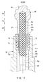
- FIGS. 1 and 2 show a glow plug 1 according to a first embodiment.
- a direction which is parallel to the axis AX of the glow plug 1 and the axis BX of a center rod member 40 coaxial therewith is defined as an axial direction HJ
- a side (in the axial direction HJ) where a ceramic heater 20 is disposed is defined as a forward end side GS
- the side opposite thereto is defined as a rear end side GK.
- the glow plug 1 is attached to a combustion chamber (not shown) of a diesel engine and is used as a heat source for assisting ignition at the time of startup of the engine.
- the glow plug 1 is constituted by a metallic shell 10, the ceramic heater 20, an outer tube 30, the center rod member 40, a connection ring (connection member) 50, a terminal member 60, etc.
- the metallic shell 10 is a tubular member which is formed of a metal (specifically, carbon steel) and which has an axial hole 10h extending therethrough in the axial direction HJ.
- the metallic shell 10 has a forward end portion (hereinafter referred to as the shell forward end portion) 11, a rear end portion (hereinafter referred to as the shell rear end portion) 15, and a trunk portion (hereinafter referred to as the shell trunk portion) 13 located therebetween.
- a mounting portion 13g is provided on the rear end side GK of the shell trunk portion 13.
- the mounting portion 13g has a male screw for attaching the glow plug 1 to an engine head (not shown) of an internal combustion engine.
- a tool engagement portion 15c having a hexagonal cross section is provided on the shell rear end portion 15.
- the shell rear end portion 15 has a taper portion 15t at its end at which the axial hole 10h is opened.
- the taper portion 15t is tapered such that the diameter of the axial hole 10h increases toward the rear end side GK.
- the ceramic heater 20 assumes a rodlike shape, and its forward end portion (hereinafter referred to as the heater forward end portion) 21 is formed to have a hemispherical curved surface.
- the ceramic heater 20 has the following structure: a heat-generating resistor 27 formed of electrically conductive ceramic (specifically, silicon-nitride ceramic which contains tungsten carbide as an electrically conductive component) is embedded in an insulating substrate 26 formed of insulating ceramic (specifically, silicon-nitride ceramic).
- the heat-generating resistor 27 has a heat-generating portion 27c, a pair of lead portions 27d and 27e, and a pair of electrode lead-out portions 27f and 27g.
- the heat-generating portion 27c is bent to a shape resembling the letter U and is disposed in the heater forward end portion 21. When electrical power is supplied to the heat-generating portion 27c, it generates heat and its temperature becomes high.
- the two lead portions 27d and 27e are connected to the respective opposite ends of the heat-generating portion 27c, and extend toward a rear end portion 25 of the ceramic heater 20 in parallel to each other (hereinafter referred to as the heater rear end portion 25).
- the two electrode lead-out portions 27f and 27g communicate with the two electrode lead portions 27d and 27e in the heater rear end portion 25, and are exposed at the outer circumference surface of the heater rear end portion 25.
- One electrode lead portion 27g is located on the rear end side GK of the other electrode lead portion 27f.
- the outer tube 30 is a tubular member formed of a metal (specifically, stainless steel) and having a tube hole 30h extending therethrough in the axial direction HJ.
- the outer tube 30 has a trunk portion (hereinafter referred to as the outer tube trunk portion) 31 located on the forward end side GS, a fitting portion (hereinafter referred to as the outer tube fitting portion) 35 located on the rear end side GK, and a flange portion (hereinafter referred to as the outer tube flange portion) 33 located therebetween.
- the outer tube trunk portion 31 has a cylindrical shape.
- the outer tube flange portion 33 has a diameter greater than that of the outer tube trunk portion 31.
- the outer tube fitting portion 35 has a stepped shape for fitting to the shell forward end portion 11 of the metallic shell 10.
- the ceramic heater 20 is inserted into the tube hole 30h of the outer tube 30, and is held from the radially outer side in a state in which the heater forward end portion 21 of the ceramic heater 20 projects toward the forward end side GS, and the heater rear end portion 25 projects toward the rear end side GK.
- one electrode lead-out portion 27f of the ceramic heater 20 is brought into contact with the outer tube 30 and is electrically connected to the outer tube 30.
- the outer tube fitting portion 35 of the outer tube 30 is laser-welded to the shell forward end portion 11 of the metallic shell 10 in a state in which the outer tube fitting portion 35 is fitted into the shell forward end portion 11.
- the ceramic heater 20 is held on the forward end side GS of the metallic shell 10 through the outer tube 30.
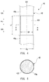
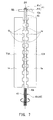
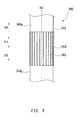
- FIGS. 3 to 5 show the center rod member 40.
- the center rod member 40 is a round-rod-shaped member formed of a metal (specifically, stainless steel) and extending in the axial direction HJ (the dimension in the axial direction HJ is 100 mm).
- the center rod member 40 is inserted into the axial hole 10h of the metallic shell 10 in a state in which the center rod member 40 is insulated from the metallic shell 10.
- the center rod member 40 is formed from a coiled material having a diameter equal to the diameter Dg of non-correction portions 43g of a trunk portion 43 of the center rod member 40 (hereinafter referred to as the "center rod trunk portion 43"), which are portions of the center rod trunk portion 43 remaining after exclusion of runout correction portions 43f.
- the center rod member 40 has a forward end portion (hereinafter referred to as the center rod forward end portion) 41, a rear end portion (hereinafter referred to as the center rod rear end portion) 45, and a trunk portion (hereinafter referred to as the center rod trunk portion) 43 located therebetween.
- the center rod forward end portion 41 is a portion connected to a connection ring 50 to be described later, and is composed of a fitting portion 41s having a small diameter and a larger diameter portion 41k having a diameter greater than that of the fitting portion 41s.
- the center rod rear end portion 45 is a portion on to which a terminal member 60 to be described later is fitted, has a crisscross knurl 45i formed on the outer circumference thereof (see FIG. 2 ).
- a plurality of (specifically, 10) runout correction portions 43f (43f1 to 43f10) for correcting the circular runout of the trunk forward end portion 43s in relation to the trunk rear end portion 43k of the center rod trunk portion 43 (reference) (the runout of the center rod trunk portion 43) are formed such that they are spaced from one another in the axial direction HJ.
- the runout correction portions 43f are formed by form rolling.
- the runout correction portions 43f are portions formed to decrease the runout of the center rod trunk portion 43, as compared with the case where the runout correction portions 43f are not provided.
- each runout correction portion 43f connects itself with a non-correction portion 43g located adjacent thereto such that the axis of the runout correction portion 43f and the axis of the non-correction portion 43g located adjacent thereto obliquely intersect with each other, or connects together non-correction portions 43g located adjacent to the runout correction portion 43f such that the axes of the non-correction portions 43g obliquely intersect with each other.
- the runout correction portions 43f decrease the runout of the center rod trunk portion 43.
- each runout correction portion 43f is a diameter reduced portion which is a portion of the center rod trunk portion 43 in the axial direction HJ and has a reduced diameter over the entire circumference.
- the diameter reduced portion (the runout correction portion) 43f forms approximately rectangular recesses which are concaved inward.
- the diameter Dg of the non-correction portions 43g of the center rod trunk portion 43 is 2.700 mm
- the diameter Df of the runout correction portions (the diameter reduced portions) 43f is 2.655 mm.
- the runout correction portions 43f are disposed at equal intervals (specifically, intervals of 7.0 mm) such that the spacing between runout correction portions 43f adjacent to each other becomes 3.5 mm (such that the dimension Lg1 of a non-correction portion 43g1 located between the runout correction portions 43f in the axial direction HJ becomes 3.5 mm).
- the runout correction portions 43f are formed on the entirety of the center rod trunk portion 43 in the axial direction HJ in a well balanced manner.
- one runout correction portion 43f5 is formed at the center HJC of the center rod trunk portion 43 in the axial direction HJ, four runout correction portions 43f1 to 43f4 are disposed on the forward end side GS of the center, and five runout correction portions 43f6 to 43f10 are disposed on the rear end side GK of the center.
- the dimension Lg2 (in the axial direction HJ) of the non-correction portion 43g2 located on the endmost position on the forward end side GS is 10.0 mm.
- connection ring 50 is a tubular member which is formed of a metal (specifically, stainless steel) and which connects the heater rear end portion 25 of the ceramic heater 20 and the center rod forward end portion 41 of the center rod member 40.
- the connection ring 50 is disposed in the metallic shell 10 such that the connection ring 50 is spaced from the metallic shell 10.
- the heater rear end portion 25 of the ceramic heater 20 is press-fitted into a forward end portion 51 of the connection ring 50 located on the forward end side GS (hereinafter referred to as the "ring forward end portion 51).
- the electrode lead-out portion 27g of the ceramic heater 20 is brought into contact with the connection ring 50, and is electrically connected to the connection ring 50.
- the center rod forward end portion 41 of the center rod member 40 is press-fitted into a rear end portion 55 of the connection ring 50 located on the rear end side (hereinafter referred to as the "ring rear end portion 55). Specifically, the fitting portion 41s of the center rod forward end portion 41 is fitted into the ring rear end portion 55, and the larger diameter portion 41k of the center rod forward end portion 41 comes into engagement with the ring rear end portion 55 to thereby position the connection ring 50. As a result, the ceramic heater 20 and the center rod member 40 are connected together through the connection ring 50.
- the terminal member 60 is a member formed of a metal, and is composed of a surrounding portion 61 located on the forward end portion GS and a terminal portion 65 located on the rear end side GK.
- the surrounding portion 61 has the shape of a tube with a bottom and has an opening on the forward end side GS.
- the surrounding portion 61 is fitted onto the center rod rear end portion 45 of the center rod member 40 and is fixed to the center rod rear end portion 45 by means of crimping.
- a portion (in-hole surrounding portion) 61s of the surrounding portion 61 located on the forward end side GS is disposed in the axial hole 10h of the metallic shell 10.
- a portion (out-hole surrounding portion) 61k of the surrounding portion 61 located on the rear end side GK of the in-hole surrounding portion 61s is disposed outside the metallic shell 10 (on the rear end side GK of the metallic shell 10).
- a step portion 61t is formed on the outer circumference of the surrounding portion 61.
- the terminal portion 65 is a portion onto which a plug cap (not shown) is fitted when the glow plug 1 is attached to the engine head and which is used as a power supply terminal.
- an O-ring 71 and an insulating spacer 73 are disposed (in a cylindrical tubular space) between the shell rear end portion 15 of the metallic shell 10 and the in-hole surrounding portion 61s of the terminal member 60 in this order from the forward end side GS.
- the O-ring 71 is formed of an insulating elastic rubber (specifically, fluororubber). The O-ring 71 seals the axial hole 10h by establishing a gastight seal between the shell rear end portion 15 of the metallic shell 10 and the in-hole surrounding portion 61s of the terminal member 60 while insulating them from each other.
- the insulating spacer 73 is a tubular member formed of an insulating material (specifically, nylon).
- the insulating spacer 73 is located on the rear end side GK of the O-ring 71, and reliably separates the shell rear end portion 15 of the metallic shell 10 and the in-hole surrounding portion 61s of the terminal member 60 to thereby prevent formation of a short circuit which would otherwise occur due to contact therebetween.
- One end of the insulating spacer 73 located on the rear end side GK has a diameter greater than that of the other end thereof located on the forward end side GS.
- the insulating spacer 73 when the insulating spacer 73 is inserted into the metallic shell 10 from the rear end side GK, the insulating spacer 73 comes into engagement with the taper portion 15t of the metallic shell 10, whereby the insertion depth in the axial direction HJ is limited. Meanwhile, the insulating spacer 73 is engaged with the step portion 61t of the terminal member 60. Therefore, the insulating spacer 73 is urged toward the forward end side GS by the terminal member 60.
- the center rod trunk portion 43 of the center rod member 40 has the plurality of runout correction portions 43f which are adapted to correct the runout of the center rod trunk portion 43 and spaced from one another in the axial direction HJ. Namely, the runout of the center rod trunk portion 43 is suppressed (the coaxiality of the axis of the trunk forward end portion 43s in relation to the axis of the trunk rear end portion 43k serving as a reference axis is made smaller), as compared with the case where the runout correction portions 43f are not provided on the center rod trunk portion 43.
- the glow plug 1 in which this center rod member 40 is used can reduce the bending stress acting on the ceramic heater 20 held on the forward end side of the metallic shell 10 and connected to the center rod member 40 through the connection ring 50. Therefore, the glow plug 1 is unlikely to suffer cracking of the ceramic heater 20 and is high in reliability.
- the runout correction portions 43f are diameter reduced portions which are portions of the center rod trunk portion 43 in the axial direction HJ and which are reduced in diameter over the entire circumference. Since the runout correction portions 43f are diameter reduced portions reduced in diameter over the entire circumference, bending of the center rod trunk portion 43 in any direction can be corrected. Therefore, the runout of the center rod trunk portion 43 (consequently, the runout of the center rod member 40) can be suppressed without fail. Accordingly, the glow plug 1 in which the center rod member 40 is used can reliably decrease the bending stress acting on the ceramic heater 20 without fail, and is unlikely to suffer cracking of the ceramic heater 20.
- the center rod trunk portion 43 has a plurality of runout correction portions 43f on each of the forward end side GS and the rear end side GK in relation to the center HJC thereof in the axial direction HJ.
- the dimensions Lf of the runout correction portions 43f in the axial direction HJ are made equal to one another, and the runout correction portions 43f are formed at equal intervals in the axial direction HJ.
- the runout of the center rod trunk portion 43 can be corrected by each of the runout correction portions 43f having the same dimension and provided at equal intervals. Therefore, it is possible to correct the bending of the entirety of the center rod trunk portion 43 without fail to thereby suppress the runout of the center rod trunk portion 43 (consequently, the runout of the center rod member 40) without fail.
- the sum Lft of the dimensions Lf of the plurality of runout correction portions 43f in the axial direction HJ is rendered smaller than the sum Lgt of the dimensions Lg1, Lg2, and Lg3 of the non-correction portion 43g in the axial direction HJ. Therefore, the force required to form the runout correction portions 43f on the center rod trunk portion 43 can be decreased, whereby cost can be lowered. Accordingly, the glow plug 1 can be made inexpensive.
- the center rod member 40 is formed by forming the runout correction portions 43f on a wire rod 40x obtained by cutting a coiled material whose diameter is equal to the diameter Dg of the non-correction portions 43g of the center rod trunk portion 43.
- the center rod member 40 is formed from a wire rod 40x obtained by cutting a coiled material, the runout of the center rod trunk portion 43 and the runout of the center rod member 40 tend to become large because the wire rod 40x often has a curved shape from the beginning.
- the glow plug 1 can properly decrease the bending stress acting on the ceramic heater 20 and is unlikely to suffer cracking of the ceramic heater 20 despite that the wire rod 40x obtained by cutting a coiled material is used as the material of the center rod member 40.
- a method of manufacturing the above-described glow plug 1 will be described.
- manufacture of the center rod member 40 will be described.
- press working is performed on the forward end side GS of the wire rod 40x (the center rod member 40) to thereby form the fitting portion 41s and the larger diameter portion 41k on the center rod forward end portion 41.
- knurling is performed on the rear end side GK of the wire rod 40x (the center rod member 40) to thereby form the crisscross knurl 45i on the outer circumference of the center rod rear end portion 45.
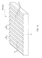
- each rolling die TD1, TD2 is composed of a plate-shaped portion ta having the shape of a rectangular plate, and a plurality of (specifically, 10) ridges tb provided on one main face of the plate-shaped portion ta.
- a portion of the wire rod 40x (the center rod member 40) corresponding to the trunk forward end portion 43s of the center rod trunk portion 43 is supported by a support member SB such that the wire rod 40x can rotate about an axis BX.
- the center rod trunk portion 43 of the wire rod 40x (the center rod member 40) is held and pressed (from the left and right sides in FIG. 7 ) by the two rolling dies TD1 and TD2
- the two rolling dies TD1 and TD2 are relatively moved in opposite directions in the direction in which the rides tb extend (the direction perpendicular to the sheet of FIG. 7 ).
- one rolling die TD1 (on the right side in FIG. 7 ) is moved from the front side of the sheet toward the back side thereof, and the other rolling die TD2 (on the left side in FIG. 7 ) is moved from the back side of the sheet toward the front side thereof.
- the center rod trunk portion 43 is rotated about the axis BX.
- portions of the center rod trunk portion 43 are reduced in diameter over the entire circumference, whereby the plurality of runout correction portions 43f are formed on the center rod trunk portion 43.
- the center rod member 40 is completed.
- the ceramic heater 20 and the connection ring 50 are prepared, and the heater rear end portion 25 of the ceramic heater 20 is press-fitted into the ring forward end portion 51 of the connection ring 50.
- the outer tube 30 is prepared, and the ceramic heater 20 is press-fitted into the tube hole 30h of the outer tube 30 such that the heater forward end portion 21 projects from the outer tube 30 toward the forward end side GS and the heater rear end portion 25 projects from the outer tube 30 toward the rear end side GK.
- the fitting portion 41s of the center rod forward end portion 41 of the above-described center rod member 40 is press-fitted into the ring rear end portion 55 of the connection ring 50, and the larger diameter portion 41k of the center rod forward end portion 41 is engaged with the ring rear end portion 55, whereby the connection ring 50 is positioned.
- the larger diameter portion 41k of the center rod member 40 and the ring rear end portion 55 of the connection ring 50 are laser welded together.
- the metallic shell 10 is prepared, and the center rod member 40 united with the ceramic heater 20, etc. is inserted into the axial hole 10h of the metallic shell 10 from the forward end side GS.
- the outer tube fitting portion 35 of the outer tube 30 is then fitted into the shell forward end portion 11 of the metallic shell 10, and they are laser-welded together.
- the terminal member 60, the insulating spacer 73, and the O-ring 71 are prepared.
- the insulating spacer 73 is fitted onto the in-hole surrounding portion 61s of the terminal member 60
- the O-ring 71 is fitted onto the in-hole surrounding portion 61s to be located on the forward end side GS of the insulating spacer 73.
- the in-hole surrounding portion 61s of the terminal member 60 is inserted into the axial hole 10h of the metallic shell 10 from the rear end side GK together with the O-ring 71 and the insulating spacer 73.
- the center rod rear end portion 45 of the center rod member 40 is inserted into the surrounding portion 61 of the terminal member 60.
- the surrounding portion 61 of the terminal member 60 is crimped whereby the center rod rear end portion 45 is fixed inside the surrounding portion 61.
- the glow plug 1 is completed.
- the center rod trunk portion 43 and the center rod member 40 whose runouts have been effectively corrected can be formed easily without fail, as compared with the case where the runout correction portions 43f are not provided on the center rod trunk portion 43. Accordingly, when the glow plug 1 is assembled using the center rod member 40 in the assembly step, it becomes possible to manufacture the glow plug 1 which can reduce the bending stress acting on the ceramic heater 20, is unlikely to suffer cracking of the ceramic heater 20, is high in reliability, and is inexpensive.
- the center rod members 240, 340, 440, and 540 according to the second through fifth embodiments are formed from a coiled material having a diameter equal to the diameter Dg of non-correction portions 243g, 343g, 443g, and 543g.
- the runout correction portions 243f, 343f, 443f, and 543f according to the second through fifth embodiments are rolled knurl portions.
- each of the center rod members 240, 340, 440, and 540 has a rolled knurl portion which is a portion (in the axial direction HJ) of the center rod trunk portion 243, 343, 443, 543 between the center rod forward end portion 241, 341, 441, 541 and the center rod rear end portion 245, 345, 445, 545 and which has a knurl 243i, 343i, 443i, 543i formed over the entire circumference by plastic deformation caused by form rolling.
- the runout correction portion 243f of the second embodiment is a rolled knurl portion which has a crisscross or diamond knurl 243i formed on the outer circumference thereof.
- the runout correction portion 343f of the third embodiment is a rolled knurl portion which has a longitudinal straight knurl 343i formed on the outer circumference thereof such that ridge portions extend along the axial direction HJ.
- the runout correction portion 443f of the fourth embodiment is a rolled knurl portion which has a lateral straight knurl 443i formed on the outer circumference thereof such that ridge portions extend perpendicularly to the axial direction HJ.
- the runout correction portion 543f of the fifth embodiment is a rolled knurl portion which has an angular knurl 543i formed on the outer circumference thereof such that ridge portions extend obliquely in relation to the axial direction HJ.
- the center rod trunk portion 243, 343, 443, or 543 has the plurality of runout correction portions 243f, 343f, 443f, or 543f for correcting the circular runout of the trunk forward end portion 243s, 343s, 443s, or 543s in relation to the trunk rear end portion 243k, 343k, 443k, or 543k which serves as a reference.
- the glow plugs 201, 301, 401, and 501 in which these center rod members 240, 340, 440, and 540 are used can reduce the bending stress acting on the ceramic heater 20, are unlikely to suffer cracking of the ceramic heater 20, and are high in reliability.
- the runout correction portions 243f, 343f, 443f, and 543f are rolled knurl portions which have the knurls 243i, 343i, 443i, and 543i formed on the entire circumference by form rolling. Therefore, bending of the center rod trunk portion 243, 343, 443, and 543 in any direction can be corrected, whereby the runouts of the center rod trunk portions 243, 343, 443, and 543 (consequently, the runouts of the center rod members 240, 340, 440, and 540) can be suppressed without fail.
- the glow plugs 201, 301, 401, 501 can reduce the bending stress acting on the ceramic heater 20 without fail, and are unlikely to suffer cracking of the ceramic heater 20. Portions similar to those of the first embodiment provide actions and effects similar to those of the first embodiment.
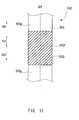
- a glow plug 601 of the sixth embodiment differs from the glow plug 1 of the first embodiment, etc., in the configuration of the glow plug 601 on the rear end side GK. Since other portions are identical to those of the first embodiment, the portions identical to those of the first embodiment will not be described or will be described only briefly.
- the glow plug 601 of the sixth embodiment has a metallic shell 10, a ceramic heater 20, an outer tube 30, a connection ring 50, etc. which are identical to those of the first embodiment. Meanwhile, a terminal member 660, an O-ring 671, an insulating spacer 673, a portion of a center rod member 640 on the rear end side GK differ from those of the first embodiment.
- its portion (the in-hole surrounding portion 61s) is disposed in the axial hole 10h of the metallic shell 10, and the remaining portion is disposed outside the metallic shell 10 (on the rear end side GK with respect to the metallic shell 10) (see FIG. 2 ).
- the terminal member 660 of the sixth embodiment its entirety is disposed outside the metallic shell 10 (on the rear end side GK with respect to the metallic shell 10) (see FIG. 12 ).
- the terminal member 660 is composed of a terminal flange portion 663 located on the forward end side GS, a terminal portion 665 located on the rear end side GK, and a surrounding portion 661 located therebetween.
- the terminal flange portion 663 is a portion which comes into contact with a spacer flange portion 673k of the insulating spacer 673 to be described later and urges the insulating spacer 673 toward the forward end side GS.
- the terminal flange portion 663 has a diameter greater than that of the axial hole 10h of the metallic shell 10.
- the surrounding portion 661 has the shape of a tube with a bottom and has an opening on the forward end side GS.
- the surrounding portion 661 is fitted onto the center rod rear end portion 645 of the center rod member 640 and is fixed to the center rod rear end portion 645 by means of crimping.
- the terminal portion 665 has the same form as that of the terminal portion 65 of the first embodiment.
- the center rod member 640 of the sixth embodiment is formed from the wire rod 40x obtained by cutting a coiled material having a diameter equal to the diameter Dg of non-correction portions 643g.
- the dimension of the center rod rear end portion 645 in the axial direction HJ is shorter than the dimension of the center rod rear end portion 45 of the first embodiment in the axial direction HJ.
- the in-hole surrounding portion 61s of the terminal member 60 is inserted into the axial hole 10h of the metallic shell 10, and the O-ring 71 and the insulating spacer 73 are disposed between the in-hole surrounding portion 61s and the metallic shell 10 (see FIG. 2 ).
- the O-ring 671 and the insulating spacer 673 are disposed between the center rod member 640 and the metallic shell 10 (see FIG. 12 ).
- the O-ring 671 forms a gastight seal between the shell rear end portion 15 of the metallic shell 10 and the center rod member 640 while insulating them from each other.
- the insulating spacer 673 is composed of a spacer insertion portion 673s located on the forward end side GS and a spacer flange portion 673k located on the rear end side GK.
- the spacer insertion portion 673s is inserted into the axial hole 10h of the metallic shell 10 so as to separate the shell rear end portion 15 of the metallic shell 10 and the center rod member 640 from each other without fail.
- the spacer flange portion 673k is larger in diameter than the axial hole 10h of the metallic shell 10, and is brought into engagement with the shell rear end portion 15 of the metallic shell 10 from the rear end side GK. Meanwhile, since the spacer flange portion 673k is in contact with the terminal flange portion 663 of the terminal member 660 as described above, the spacer flange portion 673k is urged toward the forward end side GS by the terminal member 660.
- the center rod trunk portion 643 which is a portion of the center rod member 640 located between the center rod forward end portion 641 (see FIG. 1 ) and the center rod rear end portion 645 has the plurality of runout correction portions 643f for correcting the circular runout of the trunk forward end portion 643s in relation to the trunk rear end portion 643k (reference) as in the case of the runout correction portions 43f of the first embodiment. Therefore, as compared with the case where the runout correction portions 643f are not provided (see also FIG. 1 ), the runout of the center rod trunk portion 643 is suppressed, and consequently, the runout of the center rod member 640 is suppressed.
- the glow plug 601 in which the center rod member 640 is used can reduce the bending stress acting on the ceramic heater 20, is unlikely to suffer cracking of the ceramic heater 20, and is high in reliability. Portions similar to those of the first embodiment provide actions and effects similar to those of the first embodiment.
- center rod members 40 according to the first embodiment were prepared as examples of the present invention.
- a plurality of (specifically, 10) runout correction portions 43f are formed on the center rod trunk portion 43 of each center rod member 40 such that they are spaced from one another in the axial direction HJ.
- FIG. 13 shows the results of the measurement.
- FIG. 13 shows the distribution of the runouts of the center rod members of the comparative examples and the distribution of the runouts of the center rod members of the examples.
- the manufacturing method is not limited thereto.
- the manufacturing method may be modified such that the correction portion forming step is first performed on the wire rod 40x obtained by cutting a coiled material so as to form the runout correction portions 43f on the center rod trunk portion 43, and the above-described machining operations are then performed on the portions of the wire rod 40x located on the forward end side GS and the rear end side GK.
- the number of the runout correction portions 43f or the like is not limited to 10 as in the case of the first embodiment, etc., and can be freely determined in consideration of the length, material, etc. of the center rod trunk portion 43 within a range within which the runout of the center rod trunk portion 43 can be suppressed.
Landscapes
- Engineering & Computer Science (AREA)
- Chemical & Material Sciences (AREA)
- Combustion & Propulsion (AREA)
- Mechanical Engineering (AREA)
- General Engineering & Computer Science (AREA)
- Resistance Heating (AREA)
Abstract
Description
- The present invention relates to a glow plug used to assist startup of a diesel engine, and to a method of manufacturing the same.
- A conventionally known glow plug used to assist startup of a diesel engine includes a tubular metallic shell having an axial hole, a rod-shaped ceramic heater held on the forward end side of the metallic shell, a center rod member formed of a metal and inserted into the axial hole of the metallic shell, and a connection member connecting a rear end portion of the ceramic heater and a forward end portion of the center rod member. Such a glow plug is disclosed in, for example, Patent Document 1 (see
FIG. 1 , its description, etc. in Patent Document 1). - [Patent Document 1] Japanese Patent Application Laid-Open (kokai) No.
H10-185192 - Of the components of the glow plug, the center rod member may be formed by cutting or turning a trunk portion of the center rod member such that the outer diameter of the trunk portion becomes smaller than those of forward and rear end portions of the center rod member. In such a center rod member, the rigidity (bending rigidity in the radial direction orthogonal to the axial direction) of the trunk portion of the center rod member can be lowered. Therefore, even in the case where a glow plug is assembled using a center rod member which is large in terms of the circular runout of a forward end portion thereof in relation to a rear end portion thereof (hereinafter also referred to as the "runout of the center rod member" for simplicity) (which is large in coaxiality), the bending stress acting on the ceramic heater can be reduced. Namely, since the ceramic heater is held on the forward end side of the metallic shell and is connected to the center rod member through the connection member, if the runout of the center rod member is large, the bending stress acting on the ceramic heater becomes large. However, since this bending stress is absorbed as a result of bending of the trunk portion of the center rod member which is low in rigidity, the bending stress acting on the ceramic heater can be reduced.
- In contrast, a center rod member formed such that its trunk portion has a fixed diameter over the entire length in the axial direction is advantageous in that it is unnecessary to perform cutting operation on the trunk portion of the center rod member. However, since the trunk portion of the center rod member has no portion where rigidity is low, the trunk portion of the center rod member does not easily bend as a whole. Therefore, in the case where a glow plug is assembled using a center rod member which is large in runout, a larger bending stress acts on the ceramic heater. In particular, in the case where the center rod member is formed from a wire rod obtained by cutting a coiled material, since the wire rod often has a curved shape from the beginning, the center rod member tends to have a large degree of runout. Accordingly, when a glow plug is assembled using such a center rod member, the bending stress acting on the ceramic heater tends to become large. When the bending stress acting on the ceramic heater is large, the ceramic heater may crack.
- The present invention has been made under such circumstances, and its object is to provide a glow plug whose ceramic heater is unlikely to crack and which is high in reliability and to provide a method of manufacturing such a glow plug.
- One mode of the present invention for solving the above-described problems is a glow plug comprising a tubular metallic shell having an axial hole; a rod-shaped ceramic heater held on a forward end side of the metallic shell; a center rod member formed of a metal, inserted into the axial hole of the metallic shell, and extending in an axial direction; and a connection member which connects together a rear end portion of the ceramic heater and a forward end portion of the center rod member. In the glow plug, a trunk portion of the center rod member located between the forward end portion and a rear end portion of the center rod member has a plurality of runout correction portions having corrected the circular runout of the forward end portion of the trunk portion in relation to the rear end portion of the trunk portion serving as a reference, the runout correction portions being spaced from one another in the axial direction.
- In this glow plug, the trunk portion of the center rod member has a plurality of runout correction portions for correcting the circular runout of the forward end portion of the trunk portion in relation to the rear end portion of the trunk portion serving as a reference (hereinafter also referred to as the "runout of the trunk portion of the center rod member" for simplicity). The runout correction portions are spaced from one another in the axial direction. Namely, the runout of the trunk portion of the center rod member is suppressed (the coaxiality of the axis of the forward end portion of the trunk portion in relation to the axis of the rear end portion of the trunk portion serving as a reference axis is made smaller), as compared with the case where the runout correction portions are not provided on the trunk portion of the center rod member. Therefore, even when the entirety of the center rod member, including the forward and rear end portions thereof, is viewed, the runout of the center rod member (the circular runout of the forward end portion of the center rod member in relation to the rear end portion of the center rod member serving as a reference) is suppressed (the coaxiality of the axis of the forward end portion of the center rod member in relation to the axis of the rear end portion of the center rod member serving as a reference axis is made smaller). Accordingly, the glow plug in which this center rod member is used can reduce the bending stress acting on the ceramic heater held on the forward end side of the metallic shell and connected to the center rod member through the connection member. Therefore, the glow plug is unlikely to suffer cracking of the ceramic heater and is high in reliability.
- Notably, an example of the "center rod member" is a center rod member which is formed from a wire rod obtained by cutting a coiled material, whose forward and rear end portions have been subjected to predetermined machining operations, and which has a plurality of runout correction portions formed on a trunk portion thereof. Another example of the "center rod member" is a center rod member which is formed by cutting work and which has a plurality of runout correction portions formed on a trunk portion thereof.
- The "trunk portion of the center rod member" is a portion of the center rod member located between the forward and rear end portions thereof.
- The "runout correction portions" are portions of the trunk portion of the center rod member in the axial direction formed to decrease the "runout of the trunk portion of the center rod member," as compared with the case where the "runout correction portions" are not provided. Specifically, each runout correction portion connects itself with a "non-correction portion" located adjacent thereto such that the axis of the runout correction portion and the axis of the non-correction portion located adjacent thereto obliquely intersect with each other, or connects together "non-correction portions" located adjacent to the runout correction portion such that the axes of the "non-correction portions" obliquely intersect with each other. Thus, the runout correction portions decrease the runout of the trunk portion of the center rod member.
- Preferably, each of the "runout correction portions" is formed by plastically deforming a portion of the trunk portion of the center rod member in the axial direction in a state in which the runouts of the forward and rear end portions of the trunk portion are restricted. An example of a method of plastically deforming a portion of the trunk portion of the center rod member in the axial direction is form rolling. Also, form rolling or the like operation which causes plastic deformation may be performed on a portion of the trunk portion of the center rod member in the axial direction over the entire circumference thereof or at a plurality of locations in the circumferential direction. Notably, in the case where the operation which causes plastic deformation is performed at a plurality of locations in the circumferential direction, it is preferred that the operation be performed at equal intervals in the circumferential direction.
- An example of the "runout correction portions" is a diameter reduced portion which is a portion of the trunk portion of the center rod member in the axial direction and whose diameter is reduced by plastic deformation over the entire circumference as a result of pressing from the radially outer side toward the radially inner side. Another example of the "runout correction portions" is a rolled knurl portion which is a portion of the trunk portion of the center rod member and which has a knurl formed over the entire circumference by plastic deformation caused by form rolling. Examples of the knurl include a crisscross or diamond knurl, a longitudinal straight knurl formed such that ridge portions extend along the axial direction, and a lateral straight knurl formed such that ridge portions extend perpendicularly to the axial direction. Another example of the "runout correction portions" is a male screw portion which is a portion of the trunk portion of the center rod member in the axial direction and which has a male screw formed over the entire circumference by plastic deformation caused by form rolling.
- The "runout correction portions" may be rendered identical with one another or different from one another in terms of the axial dimension and the cross sectional shape (the shape of a cross section orthogonal to the axial direction).
- The "non-correction portions" which are portions of the trunk portion of the center rod member remaining after exclusion of the runout correction portions may be rendered identical with one another or different from one another in terms of the axial dimension and the cross sectional shape (the shape of a cross section orthogonal to the axial direction).
- The "forward end portion of the center rod member" is a portion which is located on the forward end side of the trunk portion of the center rod member and which is connected to the connection member, and preferably has a form suitable for connection with the connection member. For example, in the case where a tubular connection ring is used as the connection member, the forward end portion of the center rod member has a fitting portion which is fitted into the connection ring and has a small diameter, and a larger diameter portion whose diameter is greater than that of the fitting portion and comes into contact with the connection ring when the fitting portion is inserted into the connection ring to thereby position the center rod member.
- The "rear end portion of the center rod member" is a portion located on the rear end side of the trunk portion of the center rod member. The rear end portion of the center rod member may serve a terminal portion used for connection with an external circuit, or a terminal member may be fitted onto the rear end portion of the center rod member.
- An example of the "ceramic heater" is a ceramic heater which is composed of a substrate formed of an insulating ceramic and a heat-generation resistor formed of an electrically conductive ceramic and united with the substrate. Specifically, the ceramic heater may be configured such that the heat-generation resistor formed of an electrically conductive ceramic is embedded in the substrate formed of an insulating ceramic, or may be configured such that the heat-generation resistor is exposed to the exterior of the substrate.
- An example of the "connection member" is a tubular member which is fitted, on the forward end side thereof, onto the rear end portion of the ceramic heater and is connected to the ceramic heater and which is fitted, on the rear end side thereof, onto the forward end portion of the center rod member and is connected to the center rod member.
- The "metallic shell" holds the ceramic heater directly or indirectly. For example, the ceramic heater is directly held by the forward end portion of the metallic shell by means of brazing. Alternatively, the ceramic heater is indirectly held by the forward end portion of the metallic shell via a tubular member. Specifically, the ceramic heater is inserted into a tubular member such that a portion of the ceramic heater is connected to the tubular member, and this tubular member is press-fitted into the axial hole of the metallic shell, whereby the tubular member is connected to the forward end portion of the metallic shell.
- In the above-described glow plug, preferably, the runout correction portions are diameter reduced portions which are portions of the trunk portion of the center rod member in the axial direction and which are decreased in diameter over the entire circumference.
- Since the runout correction portions are diameter reduced portions reduced in diameter over the entire circumference as described above, bending of the trunk portion of the center rod member in any direction can be corrected. Therefore, the runout of the trunk portion of the center rod member can be suppressed reliably. Accordingly, the glow plug in which the center rod member is used can reliably decrease the bending stress acting on the ceramic heater, and is unlikely to suffer cracking of the ceramic heater.
- Notably, the "diameter reduced portion" may be formed such that its cross section concaved radially inward has a rectangular shape (squarish C-like shape), a V-like shape, or a U-like shape. An example of a method of forming the diameter reduced portion through diameter reduction is form rolling.
- In the above-described glow plug, preferably, the runout correction portions are rolled knurl portions which are portions of the trunk portion of the center rod member in the axial direction and each of which has a knurl formed over the entire circumference by form rolling.
- By providing, as the runout correction portions, rolled knurl portions on which the knurls are formed over the entire circumference by form rolling as described above, bending of the trunk portion of the center rod member in any direction can be corrected. Therefore, the runout of the trunk portion of the center rod member (consequently, the runout of the center rod member) can be suppressed without fail. Accordingly, the glow plug using the center rod member can reduce the bending stress acting on the ceramic heater without fail, and is unlikely to suffer cracking of the ceramic heater.
- In the above-described glow plug, preferably, the trunk portion of the center rod member has at least one runout correction portion on each of forward and rear end sides of the center thereof in the axial direction.
- By providing the runout correction portion(s) on each of the forward and rear end sides of the trunk portion of the center rod member as described above, the runout can be corrected on both of the forward and rear end sides of the trunk portion of the center rod member. Therefore, it is possible to effectively suppress the runout of the trunk portion of the center rod member (consequently, the runout of the center rod member). Accordingly, the glow plug using the center rod member can reduce the bending stress acting on the ceramic heater without fail, and is unlikely to suffer cracking of the ceramic heater.
- In the above-described glow plug, preferably, the dimensions of the runout correction portions in the axial direction are rendered equal to one another, and the runout correction portions are formed at equal intervals in the axial direction.
- By rendering the dimensions of the runout correction portions in the axial direction equal to one another, and providing the runout correction portions at equal intervals in the axial direction as described above, the runout of the trunk portion of the center rod member can be corrected by each of the runout correction portions having the same dimension and provided at equal intervals. Therefore, it is possible to correct the bending of the entire trunk portion of the center rod member without fail to thereby suppress the runout of the trunk portion of the center rod member (consequently, the runout of the center rod member) without fail. Accordingly, the glow plug using the center rod member can reduce the bending stress acting on the ceramic heater without fail, and is unlikely to suffer cracking of the ceramic heater.
- In the above-described glow plug, preferably, the sum of the dimensions of the runout correction portions in the axial direction is smaller than the sum of the dimensions of non-correction portions which are portions of the trunk portion remaining after exclusion of the runout correction portions.
- In the case where the sum of the dimensions of the runout correction portions in the axial direction is excessively large, a large force is required to form the runout correction portions on the trunk portion of the center rod member. Therefore, a large apparatus is needed, and cost increases. Accordingly, the glow plug tends to become expensive. In contrast, in this glow plug, the sum of the dimensions of the runout correction portions in the axial direction is made smaller than the sum of the dimensions of the non-correction portions in the axial direction. Therefore, the force required to form the runout correction portions on the trunk portion of the center rod member can be decreased, whereby cost can be lowered. Accordingly, the glow plug can be rendered inexpensive.
- In the above-described glow plug, preferably, the center rod member is formed from a wire rod obtained by cutting a coiled material having a diameter equal to a diameter of the non-correction portions which are portions of the trunk portion remaining after exclusion of the runout correction portions, and the runout correction portions are formed on the wire rod.
- As described above, in the case where the center rod member is formed from a wire rod obtained by cutting a coiled material, since the wire rod often has a curved shape from the beginning, the trunk portion of the center rod member tends to have a large degree of runout, and the center rod member tends to have a large degree of runout. However, in this glow plug, since a plurality of runout correction portions are provided on the trunk portion of the center rod member such that they are spaced from one another in the axial direction, the runout of the trunk portion of the center rod member (consequently, the runout of the center rod member) can be suppressed. Accordingly, this glow plug can properly decreases the bending stress acting on the ceramic heater and is unlikely to suffer cracking of the ceramic heater despite that a wire rod obtained by cutting a coiled material is used as the material of the center rod member.
- Another mode of the present invention is a method of manufacturing a glow plug comprising a tubular metallic shell having an axial hole; a rod-shaped ceramic heater held on a forward end side of the metallic shell; a center rod member formed of a metal, inserted into the axial hole of the metallic shell, and extending in an axial direction; and a connection member which connects together a rear end portion of the ceramic heater and a forward end portion of the center rod member, wherein a trunk portion of the center rod member located between the forward end portion and a rear end portion of the center rod member has a plurality of runout correction portions having corrected the circular runout of the forward end portion of the trunk portion in relation to the rear end portion of the trunk portion serving as a reference, the runout correction portions being spaced from one another in the axial direction. The method comprises a correction portion forming step in which a wire rod obtained by cutting a coiled material having a diameter equal to a diameter of the non-correction portions which are portions of the trunk portion remaining after exclusion of the runout correction portions is used, the trunk portion of the center rod member is held and pressed by a pair of rolling dies having a plurality of ridges disposed in a stripe pattern at intervals corresponding to the runout correction portions, and the pair of rolling dies are relatively moved in opposite directions in a direction in which the ridges extend so as to rotate the trunk portion and decrease the diameters of portions of the trunk portion over the entire circumference by pressing by the ridges to thereby form the plurality of runout correction portions; and an assembly step of assembling the glow plug by using the center rod member having the runout correction portions formed thereon.
- In the method of manufacturing a glow plug, since the correction portion forming step is performed as described above, the center rod trunk portion and the center rod member whose runouts have been effectively corrected can be formed easily without fail, as compared with the case where the runout correction portions are not provided on the trunk portion of the center rod member. Accordingly, when the glow plug is assembled using such a center rod member (in an assembly step), it becomes possible to manufacture a glow plug which can reduce the bending stress acting on the ceramic heater, is unlikely to suffer cracking of the ceramic heater, and is high in reliability.
-
- [
FIG. 1 ] It is a longitudinal sectional view of a glow plug according to a first embodiment. - [
FIG. 2 ] It is a longitudinal sectional view showing, on an enlarged scale, a rear end portion of the glow plug according to the first embodiment. - [
FIG. 3 ] It relates to the first embodiment and shows a plan view of a center rod member. - [
FIG. 4 ] It relates to the first embodiment and shows a partial enlarged plan view of the center rod member. - [
FIG. 5 ] It relates to the first embodiment and shows a cross-sectional view of a runout correction portion of the center rod member (sectional view taken along line A-A inFIG. 4 ). - [
FIG. 6 ] It is an explanatory view relating to the first embodiment and showing a rolling die used in a correction portion forming step. - [
FIG. 7 ] It is an explanatory view relating to the first embodiment and showing an operation of forming runout correction portions by using rolling dies in the correction portion forming step. - [
FIG. 8 ] It relates to a second embodiment and shows a partial enlarged plan view of a center rod member. - [
FIG. 9 ] It relates to a third embodiment and shows a partial enlarged plan view of a center rod member. - [
FIG. 10 ] It relates to a fourth embodiment and shows a partial enlarged plan view of a center rod member. - [
FIG. 11 ] It relates to a fifth embodiment and shows a partial enlarged plan view of a center rod member. - [
FIG. 12 ] It is a longitudinal sectional view showing, on an enlarged scale, a rear end portion of a glow plug according to a sixth embodiment. - [
FIG. 13 ] Graph showing the runouts of the trunk portions of center rod members of examples and comparative examples. - Embodiments of the present invention will now be described with reference to the drawings.
FIGS. 1 and2 show a glow plug 1 according to a first embodiment. InFIGS. 1 and2 , a direction which is parallel to the axis AX of the glow plug 1 and the axis BX of acenter rod member 40 coaxial therewith is defined as an axial direction HJ, a side (in the axial direction HJ) where aceramic heater 20 is disposed (the lower side in the drawings) is defined as a forward end side GS, and the side opposite thereto (the upper side in the drawings) is defined as a rear end side GK. - The glow plug 1 is attached to a combustion chamber (not shown) of a diesel engine and is used as a heat source for assisting ignition at the time of startup of the engine. The glow plug 1 is constituted by a
metallic shell 10, theceramic heater 20, anouter tube 30, thecenter rod member 40, a connection ring (connection member) 50, aterminal member 60, etc. - The
metallic shell 10 is a tubular member which is formed of a metal (specifically, carbon steel) and which has anaxial hole 10h extending therethrough in the axial direction HJ. Themetallic shell 10 has a forward end portion (hereinafter referred to as the shell forward end portion) 11, a rear end portion (hereinafter referred to as the shell rear end portion) 15, and a trunk portion (hereinafter referred to as the shell trunk portion) 13 located therebetween. A mountingportion 13g is provided on the rear end side GK of theshell trunk portion 13. The mountingportion 13g has a male screw for attaching the glow plug 1 to an engine head (not shown) of an internal combustion engine. Atool engagement portion 15c having a hexagonal cross section is provided on the shellrear end portion 15. When the glow plug 1 is attached to the engine head, a tool is engaged with thetool engagement portion 15c. As shown inFIG. 2 , the shellrear end portion 15 has ataper portion 15t at its end at which theaxial hole 10h is opened. Thetaper portion 15t is tapered such that the diameter of theaxial hole 10h increases toward the rear end side GK. - Next, the
ceramic heater 20 will be described. Theceramic heater 20 assumes a rodlike shape, and its forward end portion (hereinafter referred to as the heater forward end portion) 21 is formed to have a hemispherical curved surface. Theceramic heater 20 has the following structure: a heat-generatingresistor 27 formed of electrically conductive ceramic (specifically, silicon-nitride ceramic which contains tungsten carbide as an electrically conductive component) is embedded in an insulatingsubstrate 26 formed of insulating ceramic (specifically, silicon-nitride ceramic). - The heat-generating
resistor 27 has a heat-generatingportion 27c, a pair oflead portions portions portion 27c is bent to a shape resembling the letter U and is disposed in the heaterforward end portion 21. When electrical power is supplied to the heat-generatingportion 27c, it generates heat and its temperature becomes high. The twolead portions portion 27c, and extend toward a rear end portion 25 of theceramic heater 20 in parallel to each other (hereinafter referred to as the heater rear end portion 25). The two electrode lead-outportions electrode lead portions electrode lead portion 27g is located on the rear end side GK of the otherelectrode lead portion 27f. - Next, the
outer tube 30 will be described. Theouter tube 30 is a tubular member formed of a metal (specifically, stainless steel) and having atube hole 30h extending therethrough in the axial direction HJ. Theouter tube 30 has a trunk portion (hereinafter referred to as the outer tube trunk portion) 31 located on the forward end side GS, a fitting portion (hereinafter referred to as the outer tube fitting portion) 35 located on the rear end side GK, and a flange portion (hereinafter referred to as the outer tube flange portion) 33 located therebetween. The outertube trunk portion 31 has a cylindrical shape. The outertube flange portion 33 has a diameter greater than that of the outertube trunk portion 31. The outertube fitting portion 35 has a stepped shape for fitting to the shellforward end portion 11 of themetallic shell 10. - The
ceramic heater 20 is inserted into thetube hole 30h of theouter tube 30, and is held from the radially outer side in a state in which the heaterforward end portion 21 of theceramic heater 20 projects toward the forward end side GS, and the heater rear end portion 25 projects toward the rear end side GK. As a result, one electrode lead-outportion 27f of theceramic heater 20 is brought into contact with theouter tube 30 and is electrically connected to theouter tube 30. The outertube fitting portion 35 of theouter tube 30 is laser-welded to the shellforward end portion 11 of themetallic shell 10 in a state in which the outertube fitting portion 35 is fitted into the shellforward end portion 11. As a result, theceramic heater 20 is held on the forward end side GS of themetallic shell 10 through theouter tube 30. - Next, the
center rod member 40 will be described.FIGS. 3 to 5 show thecenter rod member 40. Thecenter rod member 40 is a round-rod-shaped member formed of a metal (specifically, stainless steel) and extending in the axial direction HJ (the dimension in the axial direction HJ is 100 mm). Thecenter rod member 40 is inserted into theaxial hole 10h of themetallic shell 10 in a state in which thecenter rod member 40 is insulated from themetallic shell 10. As will be described later, thecenter rod member 40 is formed from a coiled material having a diameter equal to the diameter Dg ofnon-correction portions 43g of atrunk portion 43 of the center rod member 40 (hereinafter referred to as the "centerrod trunk portion 43"), which are portions of the centerrod trunk portion 43 remaining after exclusion ofrunout correction portions 43f. - The
center rod member 40 has a forward end portion (hereinafter referred to as the center rod forward end portion) 41, a rear end portion (hereinafter referred to as the center rod rear end portion) 45, and a trunk portion (hereinafter referred to as the center rod trunk portion) 43 located therebetween. The center rodforward end portion 41 is a portion connected to aconnection ring 50 to be described later, and is composed of afitting portion 41s having a small diameter and alarger diameter portion 41k having a diameter greater than that of thefitting portion 41s. The center rodrear end portion 45 is a portion on to which aterminal member 60 to be described later is fitted, has acrisscross knurl 45i formed on the outer circumference thereof (seeFIG. 2 ). - Next, the center
rod trunk portion 43 will be described. On the centerrod trunk portion 43, a plurality of (specifically, 10)runout correction portions 43f (43f1 to 43f10) for correcting the circular runout of the trunkforward end portion 43s in relation to the trunkrear end portion 43k of the center rod trunk portion 43 (reference) (the runout of the center rod trunk portion 43) are formed such that they are spaced from one another in the axial direction HJ. As will be described later, therunout correction portions 43f are formed by form rolling. Therunout correction portions 43f are portions formed to decrease the runout of the centerrod trunk portion 43, as compared with the case where therunout correction portions 43f are not provided. Specifically, eachrunout correction portion 43f connects itself with anon-correction portion 43g located adjacent thereto such that the axis of therunout correction portion 43f and the axis of thenon-correction portion 43g located adjacent thereto obliquely intersect with each other, or connects togethernon-correction portions 43g located adjacent to therunout correction portion 43f such that the axes of thenon-correction portions 43g obliquely intersect with each other. Thus, therunout correction portions 43f decrease the runout of the centerrod trunk portion 43. - Specifically, each
runout correction portion 43f is a diameter reduced portion which is a portion of the centerrod trunk portion 43 in the axial direction HJ and has a reduced diameter over the entire circumference. As viewed on a longitudinal cross section, the diameter reduced portion (the runout correction portion) 43f forms approximately rectangular recesses which are concaved inward. Whereas the diameter Dg of thenon-correction portions 43g of the centerrod trunk portion 43 is 2.700 mm, the diameter Df of the runout correction portions (the diameter reduced portions) 43f is 2.655 mm. The dimensions Lf of therunout correction portions 43f in the axial direction HJ are rendered equal to one another (specifically, Lf = 3.5 mm). - The
runout correction portions 43f are disposed at equal intervals (specifically, intervals of 7.0 mm) such that the spacing betweenrunout correction portions 43f adjacent to each other becomes 3.5 mm (such that the dimension Lg1 of a non-correction portion 43g1 located between therunout correction portions 43f in the axial direction HJ becomes 3.5 mm). Therunout correction portions 43f are formed on the entirety of the centerrod trunk portion 43 in the axial direction HJ in a well balanced manner. Specifically, one runout correction portion 43f5 is formed at the center HJC of the centerrod trunk portion 43 in the axial direction HJ, four runout correction portions 43f1 to 43f4 are disposed on the forward end side GS of the center, and five runout correction portions 43f6 to 43f10 are disposed on the rear end side GK of the center. - The dimension Lg2 (in the axial direction HJ) of the non-correction portion 43g2 located on the endmost position on the forward end side GS is 10.0 mm. Meanwhile, the dimension Lg3 (in the axial direction HJ) of the non-correction portion 43g3 located on the endmost position on the rear end side GK is 3.0 mm. Accordingly, the sum Lgt of the dimensions Lg1, Lg2, and Lg3 of the
non-correction portions 43g in the axial direction HJ is 44.5 mm (Lgt = 3.5×9+10.0+3.0 = 44.5 mm). In contrast, the sum Lft of the dimensions Lf of therunout correction portions 43f in the axial direction HJ is 35.0 mm (Lft = 3.5×10 = 35.0 mm). Accordingly, the sum Lft of the dimensions Lf of therunout correction portions 43f in the axial direction HJ is smaller than the sum Lgt of the dimensions Lg1, Lg2, and Lg3 of thenon-correction portions 43g in the axial direction HJ (Lft < Lgt). - Next, the
connection ring 50 will be described. As shown inFIG. 1 , theconnection ring 50 is a tubular member which is formed of a metal (specifically, stainless steel) and which connects the heater rear end portion 25 of theceramic heater 20 and the center rodforward end portion 41 of thecenter rod member 40. Theconnection ring 50 is disposed in themetallic shell 10 such that theconnection ring 50 is spaced from themetallic shell 10. The heater rear end portion 25 of theceramic heater 20 is press-fitted into aforward end portion 51 of theconnection ring 50 located on the forward end side GS (hereinafter referred to as the "ring forward end portion 51). As a result, the electrode lead-outportion 27g of theceramic heater 20 is brought into contact with theconnection ring 50, and is electrically connected to theconnection ring 50. - Meanwhile, the center rod
forward end portion 41 of thecenter rod member 40 is press-fitted into arear end portion 55 of theconnection ring 50 located on the rear end side (hereinafter referred to as the "ring rear end portion 55). Specifically, thefitting portion 41s of the center rodforward end portion 41 is fitted into the ringrear end portion 55, and thelarger diameter portion 41k of the center rodforward end portion 41 comes into engagement with the ringrear end portion 55 to thereby position theconnection ring 50. As a result, theceramic heater 20 and thecenter rod member 40 are connected together through theconnection ring 50. - Next, the
terminal member 60 will be described. Theterminal member 60 is a member formed of a metal, and is composed of a surroundingportion 61 located on the forward end portion GS and aterminal portion 65 located on the rear end side GK. The surroundingportion 61 has the shape of a tube with a bottom and has an opening on the forward end side GS. The surroundingportion 61 is fitted onto the center rodrear end portion 45 of thecenter rod member 40 and is fixed to the center rodrear end portion 45 by means of crimping. As shown inFIG. 2 , a portion (in-hole surrounding portion) 61s of the surroundingportion 61 located on the forward end side GS is disposed in theaxial hole 10h of themetallic shell 10. Meanwhile, a portion (out-hole surrounding portion) 61k of the surroundingportion 61 located on the rear end side GK of the in-hole surrounding portion 61s is disposed outside the metallic shell 10 (on the rear end side GK of the metallic shell 10). Astep portion 61t is formed on the outer circumference of the surroundingportion 61. Theterminal portion 65 is a portion onto which a plug cap (not shown) is fitted when the glow plug 1 is attached to the engine head and which is used as a power supply terminal. - Within the
axial hole 10h of themetallic shell 10, an O-ring 71 and an insulatingspacer 73 are disposed (in a cylindrical tubular space) between the shellrear end portion 15 of themetallic shell 10 and the in-hole surrounding portion 61s of theterminal member 60 in this order from the forward end side GS. The O-ring 71 is formed of an insulating elastic rubber (specifically, fluororubber). The O-ring 71 seals theaxial hole 10h by establishing a gastight seal between the shellrear end portion 15 of themetallic shell 10 and the in-hole surrounding portion 61s of theterminal member 60 while insulating them from each other. - Meanwhile, the insulating
spacer 73 is a tubular member formed of an insulating material (specifically, nylon). The insulatingspacer 73 is located on the rear end side GK of the O-ring 71, and reliably separates the shellrear end portion 15 of themetallic shell 10 and the in-hole surrounding portion 61s of theterminal member 60 to thereby prevent formation of a short circuit which would otherwise occur due to contact therebetween. One end of the insulatingspacer 73 located on the rear end side GK has a diameter greater than that of the other end thereof located on the forward end side GS. Therefore, when the insulatingspacer 73 is inserted into themetallic shell 10 from the rear end side GK, the insulatingspacer 73 comes into engagement with thetaper portion 15t of themetallic shell 10, whereby the insertion depth in the axial direction HJ is limited. Meanwhile, the insulatingspacer 73 is engaged with thestep portion 61t of theterminal member 60. Therefore, the insulatingspacer 73 is urged toward the forward end side GS by theterminal member 60. - As described above, in the glow plug 1 of the first embodiment, the center
rod trunk portion 43 of thecenter rod member 40 has the plurality ofrunout correction portions 43f which are adapted to correct the runout of the centerrod trunk portion 43 and spaced from one another in the axial direction HJ. Namely, the runout of the centerrod trunk portion 43 is suppressed (the coaxiality of the axis of the trunkforward end portion 43s in relation to the axis of the trunkrear end portion 43k serving as a reference axis is made smaller), as compared with the case where therunout correction portions 43f are not provided on the centerrod trunk portion 43. Therefore, even when the entirety of thecenter rod member 40, including the center rodforward end portion 41 and the center rodrear end portion 45, is viewed, the runout of the center rod member 40 (the circular runout of the center rodforward end portion 41 in relation to the center rodrear end portion 45 serving as a reference) is suppressed (the coaxiality of the axis of the center rodforward end portion 41 in relation to the axis of the center rodrear end portion 45 serving as a reference axis becomes smaller). Accordingly, the glow plug 1 in which thiscenter rod member 40 is used can reduce the bending stress acting on theceramic heater 20 held on the forward end side of themetallic shell 10 and connected to thecenter rod member 40 through theconnection ring 50. Therefore, the glow plug 1 is unlikely to suffer cracking of theceramic heater 20 and is high in reliability. - In the first embodiment, the
runout correction portions 43f are diameter reduced portions which are portions of the centerrod trunk portion 43 in the axial direction HJ and which are reduced in diameter over the entire circumference. Since therunout correction portions 43f are diameter reduced portions reduced in diameter over the entire circumference, bending of the centerrod trunk portion 43 in any direction can be corrected. Therefore, the runout of the center rod trunk portion 43 (consequently, the runout of the center rod member 40) can be suppressed without fail. Accordingly, the glow plug 1 in which thecenter rod member 40 is used can reliably decrease the bending stress acting on theceramic heater 20 without fail, and is unlikely to suffer cracking of theceramic heater 20. - In the first embodiment, the center
rod trunk portion 43 has a plurality ofrunout correction portions 43f on each of the forward end side GS and the rear end side GK in relation to the center HJC thereof in the axial direction HJ. By providing therunout correction portions 43f on each of the forward end side GS and the rear end side GK of the centerrod trunk portion 43 as described above, the runout can be corrected on both of the forward end side GS and the rear end side GK of the centerrod trunk portion 43. Therefore, it is possible to effectively suppress the runout of the center rod trunk portion 43 (consequently, the runout of the center rod member 40). - In the first embodiment, the dimensions Lf of the
runout correction portions 43f in the axial direction HJ are made equal to one another, and therunout correction portions 43f are formed at equal intervals in the axial direction HJ. By rendering the dimensions Lf of therunout correction portions 43f in the axial direction HJ equal to one another and providing therunout correction portions 43f at equal intervals in the axial direction HJ, the runout of the centerrod trunk portion 43 can be corrected by each of therunout correction portions 43f having the same dimension and provided at equal intervals. Therefore, it is possible to correct the bending of the entirety of the centerrod trunk portion 43 without fail to thereby suppress the runout of the center rod trunk portion 43 (consequently, the runout of the center rod member 40) without fail. - In the first embodiment, the sum Lft of the dimensions Lf of the plurality of
runout correction portions 43f in the axial direction HJ is rendered smaller than the sum Lgt of the dimensions Lg1, Lg2, and Lg3 of thenon-correction portion 43g in the axial direction HJ. Therefore, the force required to form therunout correction portions 43f on the centerrod trunk portion 43 can be decreased, whereby cost can be lowered. Accordingly, the glow plug 1 can be made inexpensive. - In the first embodiment, as will be described later, the
center rod member 40 is formed by forming therunout correction portions 43f on awire rod 40x obtained by cutting a coiled material whose diameter is equal to the diameter Dg of thenon-correction portions 43g of the centerrod trunk portion 43. In the case where thecenter rod member 40 is formed from awire rod 40x obtained by cutting a coiled material, the runout of the centerrod trunk portion 43 and the runout of thecenter rod member 40 tend to become large because thewire rod 40x often has a curved shape from the beginning. However, in the first embodiment, since the plurality ofrunout correction portions 43f spaced from one another in the axial direction HJ are provided on the centerrod trunk portion 43 of thecenter rod member 40, the runout of the center rod trunk portion 43 (consequently, the runout of the center rod member 40) can be suppressed. Accordingly, the glow plug 1 can properly decrease the bending stress acting on theceramic heater 20 and is unlikely to suffer cracking of theceramic heater 20 despite that thewire rod 40x obtained by cutting a coiled material is used as the material of thecenter rod member 40. - Next, a method of manufacturing the above-described glow plug 1 will be described. First, manufacture of the
center rod member 40 will be described. First, a coiled material having a diameter equal to the diameter Dg (= 2.700 mm) of thenon-correction portions 43g of the centerrod trunk portion 43 is prepared and is cut to obtain awire rod 40x having a predetermined dimension corresponding to the dimension of thecenter rod member 40. Next, press working is performed on the forward end side GS of thewire rod 40x (the center rod member 40) to thereby form thefitting portion 41s and thelarger diameter portion 41k on the center rodforward end portion 41. Also, knurling is performed on the rear end side GK of thewire rod 40x (the center rod member 40) to thereby form thecrisscross knurl 45i on the outer circumference of the center rodrear end portion 45. - Next, in a correction portion forming step, the plurality of
runout correction portions 43f are formed on the centerrod trunk portion 43 of thewire rod 40x (the center rod member 40) (seeFIGS. 6 and7 ). This correction portion forming step is performed by form rolling in which a pair of rolling dies TD1 and TD2 are used. As shown inFIG. 6 , each rolling die TD1, TD2 is composed of a plate-shaped portion ta having the shape of a rectangular plate, and a plurality of (specifically, 10) ridges tb provided on one main face of the plate-shaped portion ta. The width Wt of each ridge tb is equal to the dimension Lf of therunout correction portions 43f in the axial direction HJ (Wt = 3.5 mm). The plurality of ridges tb are disposed in a stripe pattern (in parallel to one another) at intervals At (= 7.0 mm) equal to the intervals of therunout correction portions 43f. - As shown in
FIG. 7 , when the correction portion forming step is performed, a portion of thewire rod 40x (the center rod member 40) corresponding to the trunkforward end portion 43s of the centerrod trunk portion 43 is supported by a support member SB such that thewire rod 40x can rotate about an axis BX. Next, in a state in which the centerrod trunk portion 43 of thewire rod 40x (the center rod member 40) is held and pressed (from the left and right sides inFIG. 7 ) by the two rolling dies TD1 and TD2, the two rolling dies TD1 and TD2 are relatively moved in opposite directions in the direction in which the rides tb extend (the direction perpendicular to the sheet ofFIG. 7 ). Specifically, one rolling die TD1 (on the right side inFIG. 7 ) is moved from the front side of the sheet toward the back side thereof, and the other rolling die TD2 (on the left side inFIG. 7 ) is moved from the back side of the sheet toward the front side thereof. As a result, the centerrod trunk portion 43 is rotated about the axis BX. As a result of pressing by the ridges tb, portions of the centerrod trunk portion 43 are reduced in diameter over the entire circumference, whereby the plurality ofrunout correction portions 43f are formed on the centerrod trunk portion 43. Thus, thecenter rod member 40 is completed. - Next, an assembly step of assembling the glow plug 1 will be described. First, the
ceramic heater 20 and theconnection ring 50 are prepared, and the heater rear end portion 25 of theceramic heater 20 is press-fitted into the ringforward end portion 51 of theconnection ring 50. Also, theouter tube 30 is prepared, and theceramic heater 20 is press-fitted into thetube hole 30h of theouter tube 30 such that the heaterforward end portion 21 projects from theouter tube 30 toward the forward end side GS and the heater rear end portion 25 projects from theouter tube 30 toward the rear end side GK. - Next, the
fitting portion 41s of the center rodforward end portion 41 of the above-describedcenter rod member 40 is press-fitted into the ringrear end portion 55 of theconnection ring 50, and thelarger diameter portion 41k of the center rodforward end portion 41 is engaged with the ringrear end portion 55, whereby theconnection ring 50 is positioned. After that, thelarger diameter portion 41k of thecenter rod member 40 and the ringrear end portion 55 of theconnection ring 50 are laser welded together. - Next, the
metallic shell 10 is prepared, and thecenter rod member 40 united with theceramic heater 20, etc. is inserted into theaxial hole 10h of themetallic shell 10 from the forward end side GS. The outertube fitting portion 35 of theouter tube 30 is then fitted into the shellforward end portion 11 of themetallic shell 10, and they are laser-welded together. - Next, the
terminal member 60, the insulatingspacer 73, and the O-ring 71 are prepared. The insulatingspacer 73 is fitted onto the in-hole surrounding portion 61s of theterminal member 60, and the O-ring 71 is fitted onto the in-hole surrounding portion 61s to be located on the forward end side GS of the insulatingspacer 73. After that, the in-hole surrounding portion 61s of theterminal member 60 is inserted into theaxial hole 10h of themetallic shell 10 from the rear end side GK together with the O-ring 71 and the insulatingspacer 73. At that time, the center rodrear end portion 45 of thecenter rod member 40 is inserted into the surroundingportion 61 of theterminal member 60. After that, the surroundingportion 61 of theterminal member 60 is crimped whereby the center rodrear end portion 45 is fixed inside the surroundingportion 61. As a result, the glow plug 1 is completed. - As described above, in the method of manufacturing the glow plug 1 of the first embodiment, since the correction portion forming step is performed as described above, the center
rod trunk portion 43 and thecenter rod member 40 whose runouts have been effectively corrected can be formed easily without fail, as compared with the case where therunout correction portions 43f are not provided on the centerrod trunk portion 43. Accordingly, when the glow plug 1 is assembled using thecenter rod member 40 in the assembly step, it becomes possible to manufacture the glow plug 1 which can reduce the bending stress acting on theceramic heater 20, is unlikely to suffer cracking of theceramic heater 20, is high in reliability, and is inexpensive. - Next, second through fifth embodiments will be described (see
FIGS. 8 to 11 ). In glow plugs 201,301, 401, and 501 according to the second through fifth embodiments, the forms ofrunout correction portions rod trunk portions runout correction portions 43f according to the first embodiment. Since other portions are identical to those of the first embodiment, the portions identical to those of the first embodiment will not be described or will be described only briefly. - As in the case of the first embodiment, the
center rod members non-correction portions runout correction portions center rod members rod trunk portion knurl - Specifically, the
runout correction portion 243f of the second embodiment (seeFIG. 8 ) is a rolled knurl portion which has a crisscross ordiamond knurl 243i formed on the outer circumference thereof. - The
runout correction portion 343f of the third embodiment (seeFIG. 9 ) is a rolled knurl portion which has a longitudinalstraight knurl 343i formed on the outer circumference thereof such that ridge portions extend along the axial direction HJ. - The
runout correction portion 443f of the fourth embodiment (seeFIG. 10 ) is a rolled knurl portion which has a lateralstraight knurl 443i formed on the outer circumference thereof such that ridge portions extend perpendicularly to the axial direction HJ. - The
runout correction portion 543f of the fifth embodiment (seeFIG. 11 ) is a rolled knurl portion which has anangular knurl 543i formed on the outer circumference thereof such that ridge portions extend obliquely in relation to the axial direction HJ. - In the second through fifth embodiments as well, the center
rod trunk portion runout correction portions rear end portion runout correction portions rod trunk portions center rod members center rod members ceramic heater 20, are unlikely to suffer cracking of theceramic heater 20, and are high in reliability. - Moreover, in the second through fifth embodiments, the
runout correction portions knurls rod trunk portion rod trunk portions center rod members ceramic heater 20 without fail, and are unlikely to suffer cracking of theceramic heater 20. Portions similar to those of the first embodiment provide actions and effects similar to those of the first embodiment. - Next, a sixth embodiment will be described (see
FIG. 12 ). Aglow plug 601 of the sixth embodiment differs from the glow plug 1 of the first embodiment, etc., in the configuration of theglow plug 601 on the rear end side GK. Since other portions are identical to those of the first embodiment, the portions identical to those of the first embodiment will not be described or will be described only briefly. - The
glow plug 601 of the sixth embodiment has ametallic shell 10, aceramic heater 20, anouter tube 30, aconnection ring 50, etc. which are identical to those of the first embodiment. Meanwhile, aterminal member 660, an O-ring 671, an insulatingspacer 673, a portion of acenter rod member 640 on the rear end side GK differ from those of the first embodiment. In the case of theterminal member 60 of the first embodiment, its portion (the in-hole surrounding portion 61s) is disposed in theaxial hole 10h of themetallic shell 10, and the remaining portion is disposed outside the metallic shell 10 (on the rear end side GK with respect to the metallic shell 10) (seeFIG. 2 ). In contrast, in the case of theterminal member 660 of the sixth embodiment, its entirety is disposed outside the metallic shell 10 (on the rear end side GK with respect to the metallic shell 10) (seeFIG. 12 ). - Specifically, the
terminal member 660 is composed of aterminal flange portion 663 located on the forward end side GS, aterminal portion 665 located on the rear end side GK, and a surroundingportion 661 located therebetween. Theterminal flange portion 663 is a portion which comes into contact with aspacer flange portion 673k of the insulatingspacer 673 to be described later and urges the insulatingspacer 673 toward the forward end side GS. Theterminal flange portion 663 has a diameter greater than that of theaxial hole 10h of themetallic shell 10. The surroundingportion 661 has the shape of a tube with a bottom and has an opening on the forward end side GS. The surroundingportion 661 is fitted onto the center rodrear end portion 645 of thecenter rod member 640 and is fixed to the center rodrear end portion 645 by means of crimping. Theterminal portion 665 has the same form as that of theterminal portion 65 of the first embodiment. As in the case of the first embodiment, thecenter rod member 640 of the sixth embodiment is formed from thewire rod 40x obtained by cutting a coiled material having a diameter equal to the diameter Dg ofnon-correction portions 643g. However, the dimension of the center rodrear end portion 645 in the axial direction HJ is shorter than the dimension of the center rodrear end portion 45 of the first embodiment in the axial direction HJ. - In the first embodiment, the in-
hole surrounding portion 61s of theterminal member 60 is inserted into theaxial hole 10h of themetallic shell 10, and the O-ring 71 and the insulatingspacer 73 are disposed between the in-hole surrounding portion 61s and the metallic shell 10 (seeFIG. 2 ). In contrast, in the sixth embodiment, the O-ring 671 and the insulatingspacer 673 are disposed between thecenter rod member 640 and the metallic shell 10 (seeFIG. 12 ). - Specifically, the O-
ring 671 forms a gastight seal between the shellrear end portion 15 of themetallic shell 10 and thecenter rod member 640 while insulating them from each other. The insulatingspacer 673 is composed of aspacer insertion portion 673s located on the forward end side GS and aspacer flange portion 673k located on the rear end side GK. Thespacer insertion portion 673s is inserted into theaxial hole 10h of themetallic shell 10 so as to separate the shellrear end portion 15 of themetallic shell 10 and thecenter rod member 640 from each other without fail. Thespacer flange portion 673k is larger in diameter than theaxial hole 10h of themetallic shell 10, and is brought into engagement with the shellrear end portion 15 of themetallic shell 10 from the rear end side GK. Meanwhile, since thespacer flange portion 673k is in contact with theterminal flange portion 663 of theterminal member 660 as described above, thespacer flange portion 673k is urged toward the forward end side GS by theterminal member 660. - In the
glow plug 601 of the sixth embodiment as well, the centerrod trunk portion 643 which is a portion of thecenter rod member 640 located between the center rod forward end portion 641 (seeFIG. 1 ) and the center rodrear end portion 645 has the plurality ofrunout correction portions 643f for correcting the circular runout of the trunk forward end portion 643s in relation to the trunkrear end portion 643k (reference) as in the case of therunout correction portions 43f of the first embodiment. Therefore, as compared with the case where therunout correction portions 643f are not provided (see alsoFIG. 1 ), the runout of the centerrod trunk portion 643 is suppressed, and consequently, the runout of thecenter rod member 640 is suppressed. Accordingly, theglow plug 601 in which thecenter rod member 640 is used can reduce the bending stress acting on theceramic heater 20, is unlikely to suffer cracking of theceramic heater 20, and is high in reliability. Portions similar to those of the first embodiment provide actions and effects similar to those of the first embodiment. - Next, there will be described the results of an experiment performed to verify the effects of the present invention. 30
center rod members 40 according to the first embodiment were prepared as examples of the present invention. As described above, a plurality of (specifically, 10)runout correction portions 43f are formed on the centerrod trunk portion 43 of eachcenter rod member 40 such that they are spaced from one another in the axial direction HJ. - Meanwhile, as comparative examples, there were prepared 30 center rod members whose trunk potions (center rod trunk portions 43) did not have the
runout correction portions 43f; i.e., center rod members in a stage immediately before the correction portion forming step was performed in the method of manufacturing the glow plug 1 of the first embodiment. - Next, each of the center rod members of examples and comparative examples was measured for the runout of the center rod trunk portion (the circular runout of the trunk forward end portion in relation to the trunk rear end portion serving as a reference).
FIG. 13 shows the results of the measurement. InFIG. 13 , the average of the runouts of the center rod trunk portions of comparative examples (average when n = 30) is defined as 100% (reference value).FIG. 13 shows the distribution of the runouts of the center rod members of the comparative examples and the distribution of the runouts of the center rod members of the examples. As is apparent fromFIG. 13 , as compared with the case of the center rod members of the comparative examples, in the case of thecenter rod members 40 of the examples, the runout of the centerrod trunk portion 43 becomes considerably small (decreases to about 20%), and the variation of the runout becomes small. This result demonstrates that the runout of the centerrod trunk portion 43 was corrected through formation of the plurality ofrunout correction portions 43f on the centerrod trunk portion 43. - Although the present invention has been described on the basis of embodiments thereof, the present invention is not limited to the above-described first through sixth embodiments and can be applied with proper modifications without departing from the scope of the invention.
- For example, in the method of manufacturing the glow plug 1 described in the first embodiment, before the correction portion forming step, a portion of the
wire rod 40x obtained by cutting a coiled material, the portion being located on the forward end side GS, is machined so as to form thefitting portion 41s and thelarger diameter portion 41k on the center rodforward end portion 41, and a portion of thewire rod 40x located on the rear end side GK is machined so as to form thecrisscross knurl 45i on the outer circumference of the center rodrear end portion 45. However, the manufacturing method is not limited thereto. For example, the manufacturing method may be modified such that the correction portion forming step is first performed on thewire rod 40x obtained by cutting a coiled material so as to form therunout correction portions 43f on the centerrod trunk portion 43, and the above-described machining operations are then performed on the portions of thewire rod 40x located on the forward end side GS and the rear end side GK. Also, the number of therunout correction portions 43f or the like is not limited to 10 as in the case of the first embodiment, etc., and can be freely determined in consideration of the length, material, etc. of the centerrod trunk portion 43 within a range within which the runout of the centerrod trunk portion 43 can be suppressed. -
- 1, 201, 301, 401, 501, 601: glow plug
- 10: metallic shell
- 10h: axial hole
- 20: ceramic heater
- 25: heater rear end portion
- 40, 240, 340, 440, 540, 640: center rod member
- 40x: wire rod
- 41, 241, 341, 441, 541, 641: center rod forward end portion
- 43, 243, 343, 443, 543, 643: center rod trunk portion
- 43s, 243s, 343s, 443s, 543s, 643s: trunk forward end portion
- 43k, 243k, 343k, 443k, 543k, 643k: trunk rear end portion
- 43f (43f1 to 43f10), 643f: runout correction portion (diameter reduced portion)
- 243f, 343f, 443f, 543f: runout correction portion (rolled knurl portion)
- 243i: crisscross knurl
- 343i: longitudinal straight knurl
- 443i: lateral straight knurl
- 543i: angular knurl
- 43g, 243g, 343g, 443g, 543g, 643g: non-correction portion
- 45, 245, 345, 445, 545, 645: center rod rear end portion
- 50: connection ring (connection member)
- BX: axis (of the center rod member
- HJ: axial direction
- GS: forward end side (in the axial direction)
- GK: rear end side (in the axial direction)
- Df: diameter (of the runout correction portions)
- Dg: diameter (of the non-correction portions)
- Lf: dimensions (of the runout correction portions in the axial direction)
- Lft: sum (of the dimensions of the runout correction portions in the axial direction)
- Lg1, Lg2, Lg3: dimensions (of the non-correction portions in the axial direction)
- Lgt: sum (of the dimensions of the non-correction portions in the axial direction)
- HJC: center (of the center rod trunk portion in the axial direction)
- TD1, TD2: rolling die
- tb: ridge
- At: interval (between ridges)
Claims (8)
- A glow plug (1, 201, 301, 401, 501, 601) comprising:a tubular metallic shell (10) having an axial hole (10h);a rod-shaped ceramic heater (20) held on a forward end side (GS) of the metallic shell (10);a center rod member (40, 240, 340, 440, 540, 640) formed of a metal, inserted into the axial hole (10h) of the metallic shell (10), and extending in an axial direction (HJ); anda connection member (50) which connects together a rear end portion (25) of the ceramic heater (20) and a forward end portion (41, 241, 341, 441, 541, 641) of the center rod member (40, 240, 340, 440, 540, 640), whereina trunk portion (43, 243, 343, 443, 543, 643) of the center rod member (40, 240, 340, 440, 540, 640) located between the forward end portion (41, 241, 341, 441, 541, 641) and a rear end portion (45, 245, 345, 445, 545, 645) of the center rod member (40, 240, 340, 440, 540, 640) has a plurality of runout correction portions (43f, 243f, 343f, 443f, 543f, 643f) having corrected the circular runout of the forward end portion (43s, 243s, 343s, 443s, 543s, 643s) of the trunk portion (43, 243, 343, 443, 543, 643) in relation to the rear end portion (43k, 243k, 343k, 443k, 543, 643k) of the trunk portion (43, 243, 343, 443, 543, 643) serving as a reference, the runout correction portions (43f, 243f, 343f, 443f, 543f, 643f) being spaced from one another in the axial direction (HJ).
- A glow plug (1, 601) according to claim 1, wherein the runout correction portions (43f, 643f) are diameter reduced portions which are portions of the trunk portion (43, 643) of the center rod member (40, 640) in the axial direction (HJ) and which are decreased in diameter over the entire circumference.
- A glow plug (201, 301, 401, 501) according to claim 1, wherein the runout correction portions (243f, 343f, 443f, 543f) are rolled knurl portions which are portions of the trunk portion (243, 343, 443, 543) of the center rod member (240, 340, 440, 540) in the axial direction (HJ) and each of which has a knurl (243i, 343i, 443i, 543i) formed over the entire circumference by form rolling.
- A glow plug (1, 201, 301, 401, 501, 601) according to any one of claims 1 to 3, wherein the trunk portion (43, 243, 343, 443, 543, 643) of the center rod member (40, 240, 340, 440, 540, 640) has at least one runout correction portion (43f, 243f, 343f, 443f, 543f, 643f) on each of a forward end side (GS) and a rear end side (GK) of a center (HJC) thereof in the axial direction (HJ).
- A glow plug (1, 201, 301, 401, 501, 601) according to any one of claims 1 to 4, wherein the dimensions (Lf) of the runout correction portions (43f, 243f, 343f, 443f, 543f, 643f) in the axial direction (HJ) are rendered equal to one another, and the runout correction portions (43f, 243f, 343f, 443f, 543f, 643f) are formed at equal intervals in the axial direction (HJ).
- A glow plug (1, 201, 301, 401, 501, 601) according to any one of claims 1 to 5, wherein the sum (Lft) of the dimensions (Lf) of the runout correction portions (43f, 243f, 343f, 443f, 543f, 643f) in the axial direction (HJ) is smaller than the sum (Lgt) of the dimensions (Lg1, Lg2, Lg3) of non-correction portions (43g, 243g, 343g, 443g, 543g, 643g) which are portions of the trunk portion (43, 243, 343, 443, 543, 643) remaining after exclusion of the runout correction portions (43f, 243f, 343f, 443f, 543f, 643f).
- A glow plug (1, 201, 301, 401, 501, 601) according to any one of claims 1 to 6, wherein the center rod member (40, 240, 340, 440, 540, 640) is formed from a wire rod (40x) obtained by cutting a coiled material having a diameter equal to a diameter (Dg) of the non-correction portions (43g, 243g, 343g, 443g, 543g, 643g) which are portions of the trunk portion (43, 243, 343, 443, 543, 643) remaining after exclusion of the runout correction portions (43f, 243f, 343f, 443f, 543f, 643f), and the runout correction portions (43f, 243f, 343f, 443f, 543f, 643f) are formed on the wire rod (40x).
- A method of manufacturing a glow plug (1, 601) comprising:a tubular metallic shell (10) having an axial hole (10h);a rod-shaped ceramic heater (20) held on a forward end side (GS) of the metallic shell (10);a center rod member (40, 640) formed of a metal, inserted into the axial hole (10h) of the metallic shell (10), and extending in an axial direction (HJ); anda connection member (50) which connects together a rear end portion (25) of the ceramic heater (20) and a forward end portion (41, 641) of the center rod member (40, 640), whereina trunk portion (43, 643) of the center rod member (40, 640) located between the forward end portion (41, 641) and a rear end portion (45, 645) of the center rod member (40, 640) has a plurality of runout correction portions (43f, 643f) having corrected the circular runout of the forward end portion (43s, 643s) of the trunk portion (43, 643) in relation to the rear end portion (43k, 643k) of the trunk portion (43, 643) serving as a reference, the runout correction portions (43f, 643f) being spaced from one another in the axial direction (HJ),the method comprising:a correction portion forming step in which a wire rod (40x) obtained by cutting a coiled material having a diameter equal to a diameter (Dg) of the non-correction portions (43g, 643g) which are portions of the trunk portion (43, 643) remaining after exclusion of the runout correction portions (43f, 643f) is used, the trunk portion (43, 643) of the center rod member (40, 640) is held and pressed by a pair of rolling dies (TD1, TD2) having a plurality of ridges (tb) disposed in a stripe pattern at intervals corresponding to the runout correction portions (43f, 643f), and the pair of rolling dies (TD1, TD2) are relatively moved in opposite directions in a direction in which the ridges (tb) extend so as to rotate the trunk portion (43, 643) and decrease the diameters of portions of the trunk portion (43, 643) over the entire circumference by pressing by the ridges (tb) to thereby form the plurality of runout correction portions (43f, 643f); andan assembly step of assembling the glow plug (1, 601) by using the center rod member (40, 640) having the runout correction portions (43f, 643f) formed thereon.
Applications Claiming Priority (1)
| Application Number | Priority Date | Filing Date | Title |
|---|---|---|---|
| JP2013217883A JP6204787B2 (en) | 2013-10-18 | 2013-10-18 | Glow plug and manufacturing method thereof |
Publications (2)
| Publication Number | Publication Date |
|---|---|
| EP2863127A1 true EP2863127A1 (en) | 2015-04-22 |
| EP2863127B1 EP2863127B1 (en) | 2020-05-20 |
Family
ID=51726445
Family Applications (1)
| Application Number | Title | Priority Date | Filing Date |
|---|---|---|---|
| EP14189334.7A Active EP2863127B1 (en) | 2013-10-18 | 2014-10-17 | Glow plug and method of manufacturing the same |
Country Status (2)
| Country | Link |
|---|---|
| EP (1) | EP2863127B1 (en) |
| JP (1) | JP6204787B2 (en) |
Cited By (2)
| Publication number | Priority date | Publication date | Assignee | Title |
|---|---|---|---|---|
| EP3267108A1 (en) * | 2016-07-04 | 2018-01-10 | NGK Spark Plug Co., Ltd. | Glow plug |
| EP3267109A1 (en) * | 2016-07-04 | 2018-01-10 | NGK Spark Plug Co., Ltd. | Glow plug |
Families Citing this family (3)
| Publication number | Priority date | Publication date | Assignee | Title |
|---|---|---|---|---|
| JP6739313B2 (en) * | 2016-07-04 | 2020-08-12 | 日本特殊陶業株式会社 | Glow plug |
| JP6739312B2 (en) * | 2016-07-04 | 2020-08-12 | 日本特殊陶業株式会社 | Glow plug |
| JP7085461B2 (en) * | 2018-11-20 | 2022-06-16 | 日本特殊陶業株式会社 | Glow plugs and methods for manufacturing glow plugs |
Citations (4)
| Publication number | Priority date | Publication date | Assignee | Title |
|---|---|---|---|---|
| US4252091A (en) * | 1978-08-11 | 1981-02-24 | Robert Bosch Gmbh | Glow plug construction |
| US4414463A (en) * | 1981-09-17 | 1983-11-08 | Sun Chemical Corporation | Diesel glow-plug ignitor |
| JPH10185192A (en) | 1996-12-21 | 1998-07-14 | Denso Corp | Ceramic glow plug and method of manufacturing the same |
| US20020195443A1 (en) * | 2001-05-31 | 2002-12-26 | Katsuhiko Tanaka | Heater and method for manufacturing the same |
Family Cites Families (3)
| Publication number | Priority date | Publication date | Assignee | Title |
|---|---|---|---|---|
| JP4623645B2 (en) * | 2004-06-29 | 2011-02-02 | 日本特殊陶業株式会社 | Glow plug |
| DE102006016566B4 (en) * | 2005-09-22 | 2008-06-12 | Beru Ag | Composite conductor, in particular for glow plugs for diesel engines |
| US9879646B2 (en) * | 2012-03-12 | 2018-01-30 | Ngk Spark Plug Co., Ltd. | Ceramic glow plug |
-
2013
- 2013-10-18 JP JP2013217883A patent/JP6204787B2/en active Active
-
2014
- 2014-10-17 EP EP14189334.7A patent/EP2863127B1/en active Active
Patent Citations (4)
| Publication number | Priority date | Publication date | Assignee | Title |
|---|---|---|---|---|
| US4252091A (en) * | 1978-08-11 | 1981-02-24 | Robert Bosch Gmbh | Glow plug construction |
| US4414463A (en) * | 1981-09-17 | 1983-11-08 | Sun Chemical Corporation | Diesel glow-plug ignitor |
| JPH10185192A (en) | 1996-12-21 | 1998-07-14 | Denso Corp | Ceramic glow plug and method of manufacturing the same |
| US20020195443A1 (en) * | 2001-05-31 | 2002-12-26 | Katsuhiko Tanaka | Heater and method for manufacturing the same |
Cited By (2)
| Publication number | Priority date | Publication date | Assignee | Title |
|---|---|---|---|---|
| EP3267108A1 (en) * | 2016-07-04 | 2018-01-10 | NGK Spark Plug Co., Ltd. | Glow plug |
| EP3267109A1 (en) * | 2016-07-04 | 2018-01-10 | NGK Spark Plug Co., Ltd. | Glow plug |
Also Published As
| Publication number | Publication date |
|---|---|
| JP2015078825A (en) | 2015-04-23 |
| EP2863127B1 (en) | 2020-05-20 |
| JP6204787B2 (en) | 2017-09-27 |
Similar Documents
| Publication | Publication Date | Title |
|---|---|---|
| EP2863127B1 (en) | Glow plug and method of manufacturing the same | |
| KR101558651B1 (en) | Glow plug and manufacturing method therefor | |
| EP2827061B1 (en) | Ceramic glow plug | |
| JP5485843B2 (en) | Glow plug and manufacturing method thereof | |
| US20050093412A1 (en) | Spark plug center electrode assembly | |
| JP2002195559A (en) | Ceramics heater type glow plug, and its manufacturing method | |
| JP5964547B2 (en) | Glow plug and manufacturing method thereof | |
| EP1457736A1 (en) | Glow plug for diesel engine and method of manufacturing the glow plug | |
| JP4175970B2 (en) | Glow plug | |
| EP1612485B2 (en) | Glow plug | |
| JP5032355B2 (en) | Spark plug manufacturing method and spark plug | |
| US20140292178A1 (en) | Spark plug having a side-mounted ground electrode | |
| JP4309757B2 (en) | Ceramic heater | |
| EP2669578B1 (en) | Glow plug | |
| JP4572492B2 (en) | Ceramic glow plug and manufacturing method thereof | |
| EP3565069B1 (en) | Ignition plug and method for manufacturing ignition plug | |
| JP6220219B2 (en) | Glow plug | |
| CN107408796B (en) | Manufacturing method of spark plug | |
| JP7085461B2 (en) | Glow plugs and methods for manufacturing glow plugs | |
| JP5301635B2 (en) | Spark plug | |
| KR101566485B1 (en) | Glow plug and method for fabricating the same | |
| JP6401022B2 (en) | Glow plug and manufacturing method thereof | |
| JP2018014178A (en) | Manufacturing method of spark plug |
Legal Events
| Date | Code | Title | Description |
|---|---|---|---|
| PUAI | Public reference made under article 153(3) epc to a published international application that has entered the european phase |
Free format text: ORIGINAL CODE: 0009012 |
|
| 17P | Request for examination filed |
Effective date: 20141017 |
|
| AK | Designated contracting states |
Kind code of ref document: A1 Designated state(s): AL AT BE BG CH CY CZ DE DK EE ES FI FR GB GR HR HU IE IS IT LI LT LU LV MC MK MT NL NO PL PT RO RS SE SI SK SM TR |
|
| AX | Request for extension of the european patent |
Extension state: BA ME |
|
| R17P | Request for examination filed (corrected) |
Effective date: 20151021 |
|
| RBV | Designated contracting states (corrected) |
Designated state(s): AL AT BE BG CH CY CZ DE DK EE ES FI FR GB GR HR HU IE IS IT LI LT LU LV MC MK MT NL NO PL PT RO RS SE SI SK SM TR |
|
| STAA | Information on the status of an ep patent application or granted ep patent |
Free format text: STATUS: EXAMINATION IS IN PROGRESS |
|
| 17Q | First examination report despatched |
Effective date: 20190910 |
|
| GRAP | Despatch of communication of intention to grant a patent |
Free format text: ORIGINAL CODE: EPIDOSNIGR1 |
|
| STAA | Information on the status of an ep patent application or granted ep patent |
Free format text: STATUS: GRANT OF PATENT IS INTENDED |
|
| INTG | Intention to grant announced |
Effective date: 20200206 |
|
| GRAS | Grant fee paid |
Free format text: ORIGINAL CODE: EPIDOSNIGR3 |
|
| GRAA | (expected) grant |
Free format text: ORIGINAL CODE: 0009210 |
|
| STAA | Information on the status of an ep patent application or granted ep patent |
Free format text: STATUS: THE PATENT HAS BEEN GRANTED |
|
| AK | Designated contracting states |
Kind code of ref document: B1 Designated state(s): AL AT BE BG CH CY CZ DE DK EE ES FI FR GB GR HR HU IE IS IT LI LT LU LV MC MK MT NL NO PL PT RO RS SE SI SK SM TR |
|
| REG | Reference to a national code |
Ref country code: GB Ref legal event code: FG4D |
|
| REG | Reference to a national code |
Ref country code: CH Ref legal event code: EP |
|
| REG | Reference to a national code |
Ref country code: DE Ref legal event code: R096 Ref document number: 602014065655 Country of ref document: DE |
|
| REG | Reference to a national code |
Ref country code: AT Ref legal event code: REF Ref document number: 1272842 Country of ref document: AT Kind code of ref document: T Effective date: 20200615 |
|
| REG | Reference to a national code |
Ref country code: LT Ref legal event code: MG4D |
|
| REG | Reference to a national code |
Ref country code: NL Ref legal event code: MP Effective date: 20200520 |
|
| PG25 | Lapsed in a contracting state [announced via postgrant information from national office to epo] |
Ref country code: IS Free format text: LAPSE BECAUSE OF FAILURE TO SUBMIT A TRANSLATION OF THE DESCRIPTION OR TO PAY THE FEE WITHIN THE PRESCRIBED TIME-LIMIT Effective date: 20200920 Ref country code: PT Free format text: LAPSE BECAUSE OF FAILURE TO SUBMIT A TRANSLATION OF THE DESCRIPTION OR TO PAY THE FEE WITHIN THE PRESCRIBED TIME-LIMIT Effective date: 20200921 Ref country code: FI Free format text: LAPSE BECAUSE OF FAILURE TO SUBMIT A TRANSLATION OF THE DESCRIPTION OR TO PAY THE FEE WITHIN THE PRESCRIBED TIME-LIMIT Effective date: 20200520 Ref country code: LT Free format text: LAPSE BECAUSE OF FAILURE TO SUBMIT A TRANSLATION OF THE DESCRIPTION OR TO PAY THE FEE WITHIN THE PRESCRIBED TIME-LIMIT Effective date: 20200520 Ref country code: SE Free format text: LAPSE BECAUSE OF FAILURE TO SUBMIT A TRANSLATION OF THE DESCRIPTION OR TO PAY THE FEE WITHIN THE PRESCRIBED TIME-LIMIT Effective date: 20200520 Ref country code: GR Free format text: LAPSE BECAUSE OF FAILURE TO SUBMIT A TRANSLATION OF THE DESCRIPTION OR TO PAY THE FEE WITHIN THE PRESCRIBED TIME-LIMIT Effective date: 20200821 Ref country code: NO Free format text: LAPSE BECAUSE OF FAILURE TO SUBMIT A TRANSLATION OF THE DESCRIPTION OR TO PAY THE FEE WITHIN THE PRESCRIBED TIME-LIMIT Effective date: 20200820 |
|
| PG25 | Lapsed in a contracting state [announced via postgrant information from national office to epo] |
Ref country code: HR Free format text: LAPSE BECAUSE OF FAILURE TO SUBMIT A TRANSLATION OF THE DESCRIPTION OR TO PAY THE FEE WITHIN THE PRESCRIBED TIME-LIMIT Effective date: 20200520 Ref country code: BG Free format text: LAPSE BECAUSE OF FAILURE TO SUBMIT A TRANSLATION OF THE DESCRIPTION OR TO PAY THE FEE WITHIN THE PRESCRIBED TIME-LIMIT Effective date: 20200820 Ref country code: RS Free format text: LAPSE BECAUSE OF FAILURE TO SUBMIT A TRANSLATION OF THE DESCRIPTION OR TO PAY THE FEE WITHIN THE PRESCRIBED TIME-LIMIT Effective date: 20200520 Ref country code: LV Free format text: LAPSE BECAUSE OF FAILURE TO SUBMIT A TRANSLATION OF THE DESCRIPTION OR TO PAY THE FEE WITHIN THE PRESCRIBED TIME-LIMIT Effective date: 20200520 |
|
| REG | Reference to a national code |
Ref country code: AT Ref legal event code: MK05 Ref document number: 1272842 Country of ref document: AT Kind code of ref document: T Effective date: 20200520 |
|
| PG25 | Lapsed in a contracting state [announced via postgrant information from national office to epo] |
Ref country code: NL Free format text: LAPSE BECAUSE OF FAILURE TO SUBMIT A TRANSLATION OF THE DESCRIPTION OR TO PAY THE FEE WITHIN THE PRESCRIBED TIME-LIMIT Effective date: 20200520 Ref country code: AL Free format text: LAPSE BECAUSE OF FAILURE TO SUBMIT A TRANSLATION OF THE DESCRIPTION OR TO PAY THE FEE WITHIN THE PRESCRIBED TIME-LIMIT Effective date: 20200520 |
|
| PG25 | Lapsed in a contracting state [announced via postgrant information from national office to epo] |
Ref country code: DK Free format text: LAPSE BECAUSE OF FAILURE TO SUBMIT A TRANSLATION OF THE DESCRIPTION OR TO PAY THE FEE WITHIN THE PRESCRIBED TIME-LIMIT Effective date: 20200520 Ref country code: SM Free format text: LAPSE BECAUSE OF FAILURE TO SUBMIT A TRANSLATION OF THE DESCRIPTION OR TO PAY THE FEE WITHIN THE PRESCRIBED TIME-LIMIT Effective date: 20200520 Ref country code: EE Free format text: LAPSE BECAUSE OF FAILURE TO SUBMIT A TRANSLATION OF THE DESCRIPTION OR TO PAY THE FEE WITHIN THE PRESCRIBED TIME-LIMIT Effective date: 20200520 Ref country code: AT Free format text: LAPSE BECAUSE OF FAILURE TO SUBMIT A TRANSLATION OF THE DESCRIPTION OR TO PAY THE FEE WITHIN THE PRESCRIBED TIME-LIMIT Effective date: 20200520 Ref country code: RO Free format text: LAPSE BECAUSE OF FAILURE TO SUBMIT A TRANSLATION OF THE DESCRIPTION OR TO PAY THE FEE WITHIN THE PRESCRIBED TIME-LIMIT Effective date: 20200520 Ref country code: ES Free format text: LAPSE BECAUSE OF FAILURE TO SUBMIT A TRANSLATION OF THE DESCRIPTION OR TO PAY THE FEE WITHIN THE PRESCRIBED TIME-LIMIT Effective date: 20200520 Ref country code: IT Free format text: LAPSE BECAUSE OF FAILURE TO SUBMIT A TRANSLATION OF THE DESCRIPTION OR TO PAY THE FEE WITHIN THE PRESCRIBED TIME-LIMIT Effective date: 20200520 Ref country code: CZ Free format text: LAPSE BECAUSE OF FAILURE TO SUBMIT A TRANSLATION OF THE DESCRIPTION OR TO PAY THE FEE WITHIN THE PRESCRIBED TIME-LIMIT Effective date: 20200520 |
|
| REG | Reference to a national code |
Ref country code: DE Ref legal event code: R097 Ref document number: 602014065655 Country of ref document: DE |
|
| PG25 | Lapsed in a contracting state [announced via postgrant information from national office to epo] |
Ref country code: PL Free format text: LAPSE BECAUSE OF FAILURE TO SUBMIT A TRANSLATION OF THE DESCRIPTION OR TO PAY THE FEE WITHIN THE PRESCRIBED TIME-LIMIT Effective date: 20200520 Ref country code: SK Free format text: LAPSE BECAUSE OF FAILURE TO SUBMIT A TRANSLATION OF THE DESCRIPTION OR TO PAY THE FEE WITHIN THE PRESCRIBED TIME-LIMIT Effective date: 20200520 |
|
| PLBE | No opposition filed within time limit |
Free format text: ORIGINAL CODE: 0009261 |
|
| STAA | Information on the status of an ep patent application or granted ep patent |
Free format text: STATUS: NO OPPOSITION FILED WITHIN TIME LIMIT |
|
| 26N | No opposition filed |
Effective date: 20210223 |
|
| PG25 | Lapsed in a contracting state [announced via postgrant information from national office to epo] |
Ref country code: SI Free format text: LAPSE BECAUSE OF FAILURE TO SUBMIT A TRANSLATION OF THE DESCRIPTION OR TO PAY THE FEE WITHIN THE PRESCRIBED TIME-LIMIT Effective date: 20200520 |
|
| REG | Reference to a national code |
Ref country code: CH Ref legal event code: PL |
|
| GBPC | Gb: european patent ceased through non-payment of renewal fee |
Effective date: 20201017 |
|
| PG25 | Lapsed in a contracting state [announced via postgrant information from national office to epo] |
Ref country code: LU Free format text: LAPSE BECAUSE OF NON-PAYMENT OF DUE FEES Effective date: 20201017 Ref country code: MC Free format text: LAPSE BECAUSE OF FAILURE TO SUBMIT A TRANSLATION OF THE DESCRIPTION OR TO PAY THE FEE WITHIN THE PRESCRIBED TIME-LIMIT Effective date: 20200520 |
|
| REG | Reference to a national code |
Ref country code: BE Ref legal event code: MM Effective date: 20201031 |
|
| PG25 | Lapsed in a contracting state [announced via postgrant information from national office to epo] |
Ref country code: FR Free format text: LAPSE BECAUSE OF NON-PAYMENT OF DUE FEES Effective date: 20201031 |
|
| PG25 | Lapsed in a contracting state [announced via postgrant information from national office to epo] |
Ref country code: CH Free format text: LAPSE BECAUSE OF NON-PAYMENT OF DUE FEES Effective date: 20201031 Ref country code: BE Free format text: LAPSE BECAUSE OF NON-PAYMENT OF DUE FEES Effective date: 20201031 Ref country code: LI Free format text: LAPSE BECAUSE OF NON-PAYMENT OF DUE FEES Effective date: 20201031 Ref country code: GB Free format text: LAPSE BECAUSE OF NON-PAYMENT OF DUE FEES Effective date: 20201017 |
|
| PG25 | Lapsed in a contracting state [announced via postgrant information from national office to epo] |
Ref country code: IE Free format text: LAPSE BECAUSE OF NON-PAYMENT OF DUE FEES Effective date: 20201017 |
|
| PG25 | Lapsed in a contracting state [announced via postgrant information from national office to epo] |
Ref country code: TR Free format text: LAPSE BECAUSE OF FAILURE TO SUBMIT A TRANSLATION OF THE DESCRIPTION OR TO PAY THE FEE WITHIN THE PRESCRIBED TIME-LIMIT Effective date: 20200520 Ref country code: MT Free format text: LAPSE BECAUSE OF FAILURE TO SUBMIT A TRANSLATION OF THE DESCRIPTION OR TO PAY THE FEE WITHIN THE PRESCRIBED TIME-LIMIT Effective date: 20200520 Ref country code: CY Free format text: LAPSE BECAUSE OF FAILURE TO SUBMIT A TRANSLATION OF THE DESCRIPTION OR TO PAY THE FEE WITHIN THE PRESCRIBED TIME-LIMIT Effective date: 20200520 |
|
| PG25 | Lapsed in a contracting state [announced via postgrant information from national office to epo] |
Ref country code: MK Free format text: LAPSE BECAUSE OF FAILURE TO SUBMIT A TRANSLATION OF THE DESCRIPTION OR TO PAY THE FEE WITHIN THE PRESCRIBED TIME-LIMIT Effective date: 20200520 |
|
| REG | Reference to a national code |
Ref country code: DE Ref legal event code: R081 Ref document number: 602014065655 Country of ref document: DE Owner name: NITERRA CO., LTD., NAGOYA-SHI, JP Free format text: FORMER OWNER: NGK SPARK PLUG CO., LTD., NAGOYA-SHI, AICHI-KEN, JP |
|
| PGFP | Annual fee paid to national office [announced via postgrant information from national office to epo] |
Ref country code: DE Payment date: 20250902 Year of fee payment: 12 |