EP2863075A1 - Aircraft washer - Google Patents
Aircraft washer Download PDFInfo
- Publication number
- EP2863075A1 EP2863075A1 EP20140188542 EP14188542A EP2863075A1 EP 2863075 A1 EP2863075 A1 EP 2863075A1 EP 20140188542 EP20140188542 EP 20140188542 EP 14188542 A EP14188542 A EP 14188542A EP 2863075 A1 EP2863075 A1 EP 2863075A1
- Authority
- EP
- European Patent Office
- Prior art keywords
- pipe end
- tab
- pipe
- locking washer
- locking
- Prior art date
- Legal status (The legal status is an assumption and is not a legal conclusion. Google has not performed a legal analysis and makes no representation as to the accuracy of the status listed.)
- Granted
Links
Images


Classifications
-
- F—MECHANICAL ENGINEERING; LIGHTING; HEATING; WEAPONS; BLASTING
- F16—ENGINEERING ELEMENTS AND UNITS; GENERAL MEASURES FOR PRODUCING AND MAINTAINING EFFECTIVE FUNCTIONING OF MACHINES OR INSTALLATIONS; THERMAL INSULATION IN GENERAL
- F16B—DEVICES FOR FASTENING OR SECURING CONSTRUCTIONAL ELEMENTS OR MACHINE PARTS TOGETHER, e.g. NAILS, BOLTS, CIRCLIPS, CLAMPS, CLIPS OR WEDGES; JOINTS OR JOINTING
- F16B39/00—Locking of screws, bolts or nuts
- F16B39/02—Locking of screws, bolts or nuts in which the locking takes place after screwing down
- F16B39/10—Locking of screws, bolts or nuts in which the locking takes place after screwing down by a plate, spring, wire or ring immovable with regard to the bolt or object and mainly perpendicular to the axis of the bolt
- F16B39/108—Locking of screws, bolts or nuts in which the locking takes place after screwing down by a plate, spring, wire or ring immovable with regard to the bolt or object and mainly perpendicular to the axis of the bolt with a locking washer under the nut or bolt head having at least one tongue or lug folded against the nut or bolt head, or against the object itself
-
- F—MECHANICAL ENGINEERING; LIGHTING; HEATING; WEAPONS; BLASTING
- F16—ENGINEERING ELEMENTS AND UNITS; GENERAL MEASURES FOR PRODUCING AND MAINTAINING EFFECTIVE FUNCTIONING OF MACHINES OR INSTALLATIONS; THERMAL INSULATION IN GENERAL
- F16L—PIPES; JOINTS OR FITTINGS FOR PIPES; SUPPORTS FOR PIPES, CABLES OR PROTECTIVE TUBING; MEANS FOR THERMAL INSULATION IN GENERAL
- F16L15/00—Screw-threaded joints; Forms of screw-threads for such joints
- F16L15/08—Screw-threaded joints; Forms of screw-threads for such joints with supplementary elements
-
- F—MECHANICAL ENGINEERING; LIGHTING; HEATING; WEAPONS; BLASTING
- F16—ENGINEERING ELEMENTS AND UNITS; GENERAL MEASURES FOR PRODUCING AND MAINTAINING EFFECTIVE FUNCTIONING OF MACHINES OR INSTALLATIONS; THERMAL INSULATION IN GENERAL
- F16L—PIPES; JOINTS OR FITTINGS FOR PIPES; SUPPORTS FOR PIPES, CABLES OR PROTECTIVE TUBING; MEANS FOR THERMAL INSULATION IN GENERAL
- F16L19/00—Joints in which sealing surfaces are pressed together by means of a member, e.g. a swivel nut, screwed on, or into, one of the joint parts
- F16L19/005—Joints in which sealing surfaces are pressed together by means of a member, e.g. a swivel nut, screwed on, or into, one of the joint parts comprising locking means for the threaded member
-
- Y—GENERAL TAGGING OF NEW TECHNOLOGICAL DEVELOPMENTS; GENERAL TAGGING OF CROSS-SECTIONAL TECHNOLOGIES SPANNING OVER SEVERAL SECTIONS OF THE IPC; TECHNICAL SUBJECTS COVERED BY FORMER USPC CROSS-REFERENCE ART COLLECTIONS [XRACs] AND DIGESTS
- Y10—TECHNICAL SUBJECTS COVERED BY FORMER USPC
- Y10T—TECHNICAL SUBJECTS COVERED BY FORMER US CLASSIFICATION
- Y10T29/00—Metal working
- Y10T29/49—Method of mechanical manufacture
- Y10T29/49826—Assembling or joining
- Y10T29/49947—Assembling or joining by applying separate fastener
- Y10T29/49954—Fastener deformed after application
Definitions
- the present invention concerns an aircraft pipe joint. More particularly, but not exclusively, this invention concerns a washer for use in an aircraft pipe joint.
- Aircraft pipe joints for example in aircraft fuel systems, often include a washer disposed between a first pipe end and a second pipe end.
- the first pipe end and second pipe end are typically connected with at least one nut disposed on the outer surface of either the first pipe end or second pipe end.
- Pipe joints for example slat track drain hose connections, may require "double locking" in order to comply with aircraft safety regulations.
- Such a double locking arrangement may be provided by first locking the pipe joint by the engagement of the pipe connectors.
- Such an arrangement may be, for example, a nut on disposed on the outer surface of a pipe end. Wire locking may be used to provide a secondary lock on the drain hoses.
- wire locking may result in fragments of wire entering the aircraft fuel filter system and causing damage.
- the present invention seeks to mitigate the above-mentioned problems. Alternately or additionally, the present invention seeks to provide an improved aircraft pipe coupling arrangement.
- the invention provides a locking washer for an aircraft pipe joint, comprising a main body providing an aperture, and a first tab and a second tab disposed at the edge of the main body, the first tab and/or second tab being arranged to be deformable, to allow engagement of the first tab with a first pipe end and the second tab with a second pipe end.
- the first tab may be engaged with a nut on the first pipe end.
- the second tab may be engaged with a nut on the second pipe end.
- the first tab and/or second tab may be at least partially pre-deformed for engagement with a pipe end. Such an arrangement may speed up the installation of the locking washer in place.
- the first tab and second tab may be at least partially pre-deformed for engagement with a pipe end, the first tab being pre-deformed in the opposite direction to the second tab.
- At least one of the first tab and second tab may be arranged to be more easily deformed in a particular direction.
- Such an arrangement may comprise an area between the tab and the main body of the washer being weakened. The weakening may be as a result of material being removed in this section or "stamping" of the section.
- Such an arrangement may enable the easier installation of the locking washer.
- the first tab may be arranged to be more easily deformed in a first direction
- the second tab may be arranged to be more easily deformed in a second, opposite, direction.
- the locking washer may comprise a metal material.
- the first tab and/or second tab may extend at an angle to, preferably approximately perpendicular to, a plane defined by the main body of the washer.
- the locking washer may comprise three, four, five, or six tabs for engagement with a first pipe end or second pipe end.
- an aircraft pipe coupling comprising a first pipe end and a second pipe end, and a locking washer disposed between the first pipe end and second pipe end, the locking washer comprising a first tab in engagement with the first pipe end, and a second tab in engagement with the second pipe end.
- the first tab and/or second tab of the locking washer may be deformable to allow the engagement of the tabs with the appropriate pipe end.
- the locking washer may comprise a metal material.
- the locking washer may comprise a main body, the main body defining an aperture through which the first pipe end and second pipe end may be joined.
- the first tab and/or second tab may extend at an angle to, preferably approximately perpendicular to, a plane defined by the main body of the washer.
- the first pipe end and/or second pipe end may comprise a primary locking mechanism, for example a nut.
- the first and/or second tab may be engaged with at least part of the primary locking mechanism, for example a side face of the primary locking mechanism.
- the locking washer may provide a secondary locking mechanism for the pipe coupling. Such an arrangement allows the double locking of a pipe coupling without requiring a secondary wire locking arrangement.
- the pipe coupling may comprise a drain port connected to the first pipe end and a drain pipe connected to the second pipe end.
- the pipe coupling may comprise a drain to remove water from a slat track housing (also known as a slat track can).
- the locking washer may comprise one or more additional tabs for engagement with the first pipe end or second pipe end.
- the locking washer may comprise three, four, five, or six tabs for engagement with the first pipe end or second pipe end. At least one tab on the locking washer may be at least partially pre-deformed to improve the ease of installation of the locking washer.
- the pre-deformation may comprise deforming the tab such that it is approximately perpendicular to the main body of the locking washer.
- the step of deforming the first tab to engage with the first pipe end may take place prior to engaging the first pipe end with the second pipe end.
- the first tab of the locking washer may be deformed prior to engaging the locking washer with the first pipe end.
- the locking washer is supplied with a first tab pre-deformed into the appropriate position for engagement with the first pipe end.
- the deformation of the first tab may take place after the first pipe end has been engaged with the second pipe end.
- the method may include an additional step of locking the first pipe end and second pipe end together with a primary locking mechanism.
- the primary locking mechanism may comprise a threaded arrangement, whereby the first pipe end and second pipe end are screwed together.
- the locking washer may act as a secondary locking mechanism, opposing any rotational (unscrewing) movement of the first pipe end relative to the second pipe end. The deformation of the first tab may take place prior to the locking tab being disposed between the first pipe end and second pipe end.
- the invention provides an aircraft fuel system, the aircraft fuel system comprising a pipe coupling according to the second aspect of the invention, or a locking washer according to the first aspect of the invention.
- the invention provides an aircraft, the aircraft comprising a pipe coupling according to the second aspect of the invention, a locking washer according to the first aspect of the invention, or an aircraft fuel system according to the fourth aspect of the invention.
- FIG 1 shows a locking washer 10 according to a first embodiment of the invention.
- the locking washer 10 comprises a main body 12, a first tab 14, and a second tab 16.
- the first tab 14 shown in figure 1 has already been deformed for allowing engagement with a pipe end fitting.
- the main body 12 defines an aperture 18 through which a part of a pipe end fitting may be passed to allow joining with another pipe end fitting.
- the second tab When installed in a pipe coupling, the second tab may be deformed, such that it extends in the opposite direction to the first tab, with both the first tab and second tab being perpendicular to the plane being defined by the main body.
- the tab may be deformed by an engineer using a hammer.
- the base of the tabs 14, 16, where they join to the main body 12, may be arranged to be more easily deformed in one direction as compared to another direction. This may be as a result of the base of the tab being weakened in one direction, for example by stamping or removal of material from the base of the tab.
- Figure 2 shows the locking washer according to the first embodiment of the invention in an aircraft pipe coupling according to a second embodiment of the invention.
- a track can drain in an aircraft wing provides a first pipe end 20 to which a flexible hose 22 is connected, the flexible hose providing the second pipe end 26.
- the flexible hose 22 leads to drain port 24 in the lower cover of the wing.
- the locking arrangements at both the track can drain and the drain port 24 are the same, and so will only be described for the connection of the hose 22 with the first pipe end 20 of the track can drain.
- the first pipe end 20 and the second pipe end 26 are threaded to facilitate the screwing together of the first pipe end 20 and the second pipe end 26.
- the locking washer 10 is threaded between the first pipe end 20 and the second pipe end 26 prior to the two pipe ends being screwed together.
- Each pipe end includes a hexagonal head to allow the tightening together of the two pipe ends by using a spanner.
- Figures 3A, 3B, and 3C show front and side views of a locking washer according to a third embodiment of the invention, similar to the locking washer shown in figure 1 .
- the locking washer of figures 3A, 3B, and 3C has a main body defining a circular aperture, whereas in figure 1 the main body defines a twelve-sided aperture.
- Figure 3C shows the first tab and second tab being pre-bent prior to installation. Such pre-bending may make it easier to install the washers in typically cramped aircraft environments.
- FIGS 4A, 4B, 4C, and 4D show a locking washer 40 according to a third embodiment of the invention.
- the locking washer comprises a third and fourth tab which may be deformed into contact with respective pipe ends. Such an arrangement may provide a more secure locking of a pipe joint than a locking washer having only two tabs.
- the locking washer is first slid into position on a first pipe end 42 of a drain adaptor 44.
- a first set of tabs 46 are then bent into engagement with a hexagonal head of the first pipe end 42.
- a second pipe end 47, at the end of a drain hose 48 is connected with the first pipe end 42.
- a second set of tabs 49 are then bent into engagement with a hexagonal head of the second pipe end 47.
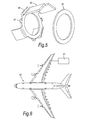
- FIG. 5 shows a locking washer 50 according to a fourth embodiment of the invention.
- the locking washer 50 may include a number of additional small tabs 52 for engagement with a packing ring 54.
- the use of a packing ring 54 may make it more straightforward to deform the tabs of the locking washer without a resulting deformation of the main body of the locking washer.
- the locking washer 50 comprises a number of tabs for engaging with a bolt head, wherein the tabs are deformable and to increase the ease of deformation include a curved "crimped" section 56.
- Figure 6 shows an aircraft 60, the aircraft comprising a fuel system 62 including a pipe coupling according to any embodiment of the invention described above.
Landscapes
- Engineering & Computer Science (AREA)
- General Engineering & Computer Science (AREA)
- Mechanical Engineering (AREA)
- Mutual Connection Of Rods And Tubes (AREA)
- Bolts, Nuts, And Washers (AREA)
- Gasket Seals (AREA)
Abstract
Description
- The present invention concerns an aircraft pipe joint. More particularly, but not exclusively, this invention concerns a washer for use in an aircraft pipe joint.
- Aircraft pipe joints, for example in aircraft fuel systems, often include a washer disposed between a first pipe end and a second pipe end. The first pipe end and second pipe end are typically connected with at least one nut disposed on the outer surface of either the first pipe end or second pipe end. For aircraft pipe joints, especially in aircraft fuel systems, it is essential that there is no leakage from the pipe joint into the surrounding environment. Such leakage can damage the aircraft, possibly in a serious manner. Pipe joints, for example slat track drain hose connections, may require "double locking" in order to comply with aircraft safety regulations. Such a double locking arrangement may be provided by first locking the pipe joint by the engagement of the pipe connectors. Such an arrangement may be, for example, a nut on disposed on the outer surface of a pipe end. Wire locking may be used to provide a secondary lock on the drain hoses.
- However, wire locking may result in fragments of wire entering the aircraft fuel filter system and causing damage.
- The present invention seeks to mitigate the above-mentioned problems. Alternately or additionally, the present invention seeks to provide an improved aircraft pipe coupling arrangement.
- According to a first aspect, the invention provides a locking washer for an aircraft pipe joint, comprising a main body providing an aperture, and a first tab and a second tab disposed at the edge of the main body, the first tab and/or second tab being arranged to be deformable, to allow engagement of the first tab with a first pipe end and the second tab with a second pipe end.
- The first tab may be engaged with a nut on the first pipe end. The second tab may be engaged with a nut on the second pipe end.
- The first tab and/or second tab may be at least partially pre-deformed for engagement with a pipe end. Such an arrangement may speed up the installation of the locking washer in place. The first tab and second tab may be at least partially pre-deformed for engagement with a pipe end, the first tab being pre-deformed in the opposite direction to the second tab. At least one of the first tab and second tab may be arranged to be more easily deformed in a particular direction. Such an arrangement may comprise an area between the tab and the main body of the washer being weakened. The weakening may be as a result of material being removed in this section or "stamping" of the section. Such an arrangement may enable the easier installation of the locking washer. The first tab may be arranged to be more easily deformed in a first direction, and the second tab may be arranged to be more easily deformed in a second, opposite, direction.
- The locking washer may comprise a metal material. The first tab and/or second tab may extend at an angle to, preferably approximately perpendicular to, a plane defined by the main body of the washer.
- The locking washer may comprise three, four, five, or six tabs for engagement with a first pipe end or second pipe end.
- According to a second aspect of the invention, there is provided an aircraft pipe coupling comprising a first pipe end and a second pipe end, and a locking washer disposed between the first pipe end and second pipe end, the locking washer comprising a first tab in engagement with the first pipe end, and a second tab in engagement with the second pipe end.
- The first tab and/or second tab of the locking washer may be deformable to allow the engagement of the tabs with the appropriate pipe end. The locking washer may comprise a metal material. The locking washer may comprise a main body, the main body defining an aperture through which the first pipe end and second pipe end may be joined. The first tab and/or second tab may extend at an angle to, preferably approximately perpendicular to, a plane defined by the main body of the washer.
- The first pipe end and/or second pipe end may comprise a primary locking mechanism, for example a nut. The first and/or second tab may be engaged with at least part of the primary locking mechanism, for example a side face of the primary locking mechanism. The locking washer may provide a secondary locking mechanism for the pipe coupling. Such an arrangement allows the double locking of a pipe coupling without requiring a secondary wire locking arrangement. The pipe coupling may comprise a drain port connected to the first pipe end and a drain pipe connected to the second pipe end. The pipe coupling may comprise a drain to remove water from a slat track housing (also known as a slat track can). The locking washer may comprise one or more additional tabs for engagement with the first pipe end or second pipe end. The locking washer may comprise three, four, five, or six tabs for engagement with the first pipe end or second pipe end. At least one tab on the locking washer may be at least partially pre-deformed to improve the ease of installation of the locking washer. The pre-deformation may comprise deforming the tab such that it is approximately perpendicular to the main body of the locking washer.
- According to a third aspect of the invention there is also provided a method of locking an aircraft pipe coupling, comprising the steps of:
- providing a first pipe end and a second pipe end,
- engaging the first pipe end and second pipe end with a locking washer disposed between the first pipe end and second pipe end, the locking washer comprising a first tab and a second tab,
- deforming the first tab to engage with the first pipe end, and
- deforming the second tab to engage with the second pipe end.
- The step of deforming the first tab to engage with the first pipe end may take place prior to engaging the first pipe end with the second pipe end. The first tab of the locking washer may be deformed prior to engaging the locking washer with the first pipe end. In such a method, the locking washer is supplied with a first tab pre-deformed into the appropriate position for engagement with the first pipe end. Alternatively, the deformation of the first tab may take place after the first pipe end has been engaged with the second pipe end.
- The method may include an additional step of locking the first pipe end and second pipe end together with a primary locking mechanism. The primary locking mechanism may comprise a threaded arrangement, whereby the first pipe end and second pipe end are screwed together. The locking washer may act as a secondary locking mechanism, opposing any rotational (unscrewing) movement of the first pipe end relative to the second pipe end. The deformation of the first tab may take place prior to the locking tab being disposed between the first pipe end and second pipe end.
- According to a fourth aspect, the invention provides an aircraft fuel system, the aircraft fuel system comprising a pipe coupling according to the second aspect of the invention, or a locking washer according to the first aspect of the invention.
- According to a fifth aspect, the invention provides an aircraft, the aircraft comprising a pipe coupling according to the second aspect of the invention, a locking washer according to the first aspect of the invention, or an aircraft fuel system according to the fourth aspect of the invention.
- It will of course be appreciated that features described in relation to one aspect of the present invention may be incorporated into other aspects of the present invention. For example, the method of the invention may incorporate any of the features described with reference to the apparatus of the invention and vice versa.
- Embodiments of the present invention will now be described by way of example only with reference to the accompanying schematic drawings of which:
- Figure 1
- shows a locking washer according to a first embodiment of the invention;
- Figure 2
- shows the locking washer of
figure 1 in a pipe connection according to a second embodiment of the invention; - Figures 3A, 3B, and 3C,
- show front and side views of a locking washer according to the third embodiment of the invention;
- Figures 4A, 4B, 4C, and 4D,
- show a locking washer and pipe connection according to a fourth embodiment of the invention,
- Figure 5
- shows a locking member according to a fifth embodiment of the invention, and
- Figure 6
- shows an aircraft according to a sixth embodiment of the invention.
-
Figure 1 shows a lockingwasher 10 according to a first embodiment of the invention. The lockingwasher 10 comprises amain body 12, afirst tab 14, and asecond tab 16. Thefirst tab 14 shown infigure 1 has already been deformed for allowing engagement with a pipe end fitting. Themain body 12 defines anaperture 18 through which a part of a pipe end fitting may be passed to allow joining with another pipe end fitting. When installed in a pipe coupling, the second tab may be deformed, such that it extends in the opposite direction to the first tab, with both the first tab and second tab being perpendicular to the plane being defined by the main body. The tab may be deformed by an engineer using a hammer. The base of thetabs main body 12, may be arranged to be more easily deformed in one direction as compared to another direction. This may be as a result of the base of the tab being weakened in one direction, for example by stamping or removal of material from the base of the tab. -
Figure 2 shows the locking washer according to the first embodiment of the invention in an aircraft pipe coupling according to a second embodiment of the invention. A track can drain in an aircraft wing provides afirst pipe end 20 to which aflexible hose 22 is connected, the flexible hose providing thesecond pipe end 26. Theflexible hose 22 leads to drainport 24 in the lower cover of the wing. The locking arrangements at both the track can drain and thedrain port 24 are the same, and so will only be described for the connection of thehose 22 with thefirst pipe end 20 of the track can drain. Thefirst pipe end 20 and thesecond pipe end 26 are threaded to facilitate the screwing together of thefirst pipe end 20 and thesecond pipe end 26. The lockingwasher 10 is threaded between thefirst pipe end 20 and thesecond pipe end 26 prior to the two pipe ends being screwed together. Each pipe end includes a hexagonal head to allow the tightening together of the two pipe ends by using a spanner. Once thefirst pipe end 20 and thesecond pipe end 26 have been screwed together, with the locking washer trapped between thefirst pipe 20 andsecond pipe end 26, thefirst tab 14 of the lockingwasher 10 is located in contact with a head of thefirst pipe end 20. Thesecond tab 16 may then be bent into contact with the head of thesecond pipe end 26. The lockingwasher 10 effectively couples together the head of thefirst pipe end 20 and the head of thesecond pipe end 26 which prevents any rotational movement of the two heads relative to each other. Thereby, the pipe joint is locked by the screwing together of the two ends, and the use of the locking washer between the heads of the two ends prevents aircraft vibrations etc. from loosening the connection between the two pipe ends by preventing relative rotational movement of the two pipe ends. -
Figures 3A, 3B, and 3C show front and side views of a locking washer according to a third embodiment of the invention, similar to the locking washer shown infigure 1 . However, in contrast tofigure 1 , the locking washer offigures 3A, 3B, and 3C , has a main body defining a circular aperture, whereas infigure 1 the main body defines a twelve-sided aperture.Figure 3C shows the first tab and second tab being pre-bent prior to installation. Such pre-bending may make it easier to install the washers in typically cramped aircraft environments. -
Figures 4A, 4B, 4C, and 4D , show a lockingwasher 40 according to a third embodiment of the invention. As can be seen, the locking washer comprises a third and fourth tab which may be deformed into contact with respective pipe ends. Such an arrangement may provide a more secure locking of a pipe joint than a locking washer having only two tabs. In the method shown infigures 4A, 4B, 4C, and 4D , the locking washer is first slid into position on afirst pipe end 42 of adrain adaptor 44. A first set oftabs 46 are then bent into engagement with a hexagonal head of thefirst pipe end 42. Asecond pipe end 47, at the end of adrain hose 48 is connected with thefirst pipe end 42. A second set oftabs 49 are then bent into engagement with a hexagonal head of thesecond pipe end 47. -
Figure 5 shows a lockingwasher 50 according to a fourth embodiment of the invention. The lockingwasher 50 may include a number of additionalsmall tabs 52 for engagement with apacking ring 54. The use of apacking ring 54 may make it more straightforward to deform the tabs of the locking washer without a resulting deformation of the main body of the locking washer. As can be seen infigure 5 , the lockingwasher 50 comprises a number of tabs for engaging with a bolt head, wherein the tabs are deformable and to increase the ease of deformation include a curved "crimped"section 56. -
Figure 6 shows anaircraft 60, the aircraft comprising afuel system 62 including a pipe coupling according to any embodiment of the invention described above. - Whilst the present invention has been described and illustrated with reference to particular embodiments, it will be appreciated by those of ordinary skill in the art that the invention lends itself to many different variations not specifically illustrated herein.
- Where in the foregoing description, integers or elements are mentioned which have known, obvious or foreseeable equivalents, then such equivalents are herein incorporated as if individually set forth. Reference should be made to the claims for determining the true scope of the present invention, which should be construed so as to encompass any such equivalents. It will also be appreciated by the reader that integers or features of the invention that are described as preferable, advantageous, convenient or the like are optional and do not limit the scope of the independent claims. Moreover, it is to be understood that such optional integers or features, whilst of possible benefit in some embodiments of the invention, may not be desirable, and may therefore be absent, in other embodiments.
Claims (15)
- A locking washer for an aircraft pipe joint, comprising a main body providing an aperture, and a first tab and a second tab disposed at the edge of the main body, the first tab and/or second tab being arranged to be deformable, to allow engagement of the first tab with a first pipe end and the second tab with a second pipe end, wherein at least one of the first tab and second tab is arranged to be more easily deformed in a particular direction.
- A locking washer as claimed in claim 1, wherein the first tab and/or second tab is at least partially pre-deformed for engagement with a pipe end.
- A locking washer as claimed in claim 1 or claim 2, wherein the first tab and second tab are at least partially pre-deformed for engagement with a pipe end, the first tab being pre-deformed in the opposite direction to the second tab.
- A locking washer as claimed in any of claims 1 to 3, wherein the first tab is arranged to be more easily deformed in a first direction, and the second tab is arranged to be more easily deformed in a second, opposite, direction.
- An aircraft pipe coupling comprising a first pipe end and a second pipe end, and a locking washer disposed between the first pipe end and second pipe end, the locking washer comprising a first tab in engagement with the first pipe end, and a second tab in engagement with the second pipe end, wherein the first tab and/or second tab of the locking washer is deformable to allow the engagement of the tab with the appropriate pipe end, and wherein at least one of the first tab and second tab is arranged to be more easily deformed in a particular direction.
- An aircraft pipe coupling as claimed in claim 5 or claim 5, wherein the locking washer comprises a main body, the main body defining an aperture through which the first pipe end and second pipe end are joined, and the first tab and/or second tab extend approximately perpendicular to a plane defined by the main body of the washer.
- An aircraft pipe coupling as claimed in either of claims 5 or 6, wherein the first pipe end and/or second pipe end comprises a primary locking mechanism and the first and/or second tab is engaged with at least part of the primary locking mechanism.
- An aircraft pipe coupling according to any of claims 5 to 7, wherein the locking washer comprises one or more further tabs for engagement with the first pipe end or second pipe end.
- A method of locking an aircraft pipe coupling, comprising the steps of:providing a first pipe end and a second pipe end,engaging the first pipe end and second pipe end with a locking washer disposed between the first pipe end and second pipe end, the locking washer comprising a first tab and a second tab wherein at least one of the first tab and second tab is arranged to be more easily deformed in a particular direction,deforming the first tab to engage with the first pipe end, anddeforming the second tab to engage with the second pipe end.
- A method as claimed in claim 9, wherein the step of deforming the first tab to engage with the first pipe end takes place prior to engaging the first pipe end with the second pipe end.
- A method as claimed in claim 9 or claim 10, wherein the first tab of the locking washer is deformed prior to engaging the locking washer with the first pipe end.
- A method as claimed in claim 9, wherein the deformation of the first tab takes place after the first pipe end has been engaged with the second pipe end.
- A method as claimed in any of claims 9 to 12, including an additional step of locking the first pipe end and second pipe end together with a primary locking mechanism.
- A method as claimed in claim 13, wherein the primary locking mechanism comprises a threaded arrangement, whereby the first pipe end and second pipe end are screwed together.
- A method as claimed in claim 14, wherein the locking washer act as a secondary locking mechanism, opposing any rotational movement of the first pipe end relative to the second pipe end.
Applications Claiming Priority (1)
| Application Number | Priority Date | Filing Date | Title |
|---|---|---|---|
| GB1318259.7A GB2519303B (en) | 2013-10-15 | 2013-10-15 | Aircraft Washer |
Publications (2)
| Publication Number | Publication Date |
|---|---|
| EP2863075A1 true EP2863075A1 (en) | 2015-04-22 |
| EP2863075B1 EP2863075B1 (en) | 2017-12-06 |
Family
ID=49680096
Family Applications (1)
| Application Number | Title | Priority Date | Filing Date |
|---|---|---|---|
| EP14188542.6A Active EP2863075B1 (en) | 2013-10-15 | 2014-10-10 | Aircraft washer |
Country Status (4)
| Country | Link |
|---|---|
| US (1) | US10184598B2 (en) |
| EP (1) | EP2863075B1 (en) |
| CN (1) | CN104565634A (en) |
| GB (1) | GB2519303B (en) |
Cited By (1)
| Publication number | Priority date | Publication date | Assignee | Title |
|---|---|---|---|---|
| EP3877685A1 (en) * | 2018-11-05 | 2021-09-15 | Swagelok Company | Mechanically locking end screw arrangements |
Families Citing this family (8)
| Publication number | Priority date | Publication date | Assignee | Title |
|---|---|---|---|---|
| US9945411B2 (en) * | 2012-08-31 | 2018-04-17 | United Technologies Corporation | Self-anti-rotating dual lock washer |
| US9273714B2 (en) * | 2013-10-04 | 2016-03-01 | Fitzhugh Lee Jackson | System and method of installing and removing a temporary concrete barrier from a bridge deck |
| JP5984098B1 (en) * | 2015-03-13 | 2016-09-06 | Smc株式会社 | Pipe fitting |
| US12085205B1 (en) | 2019-09-17 | 2024-09-10 | ASC Engineered Solutions, LLC | Pipe hanger with anti-vibration washer |
| US11359747B2 (en) * | 2019-09-17 | 2022-06-14 | ASC Engineered Solutions, LLC | Pipe hanger with lock tab washer |
| US11560969B2 (en) | 2019-09-17 | 2023-01-24 | ASC Engineered Solutions, LLC | Pipe hanger with lock tab washer |
| CN115289501A (en) * | 2022-07-05 | 2022-11-04 | 中国航发湖南动力机械研究所 | Elastic locking piece and fuel nozzle connecting structure |
| CA3206120A1 (en) * | 2022-07-15 | 2024-01-15 | Electric Line Technologies, LLC | Method and apparatus for securing threaded connections against unwanted rotation |
Citations (4)
| Publication number | Priority date | Publication date | Assignee | Title |
|---|---|---|---|---|
| GB141965A (en) * | 1919-06-20 | 1920-04-29 | James Augustus Crane | Improvements in and relating to nut locks |
| US1498686A (en) * | 1922-03-20 | 1924-06-24 | William F Farnsworth | Keeper for nuts |
| US6439616B1 (en) * | 2001-03-29 | 2002-08-27 | General Electric Company | Anti-rotation retainer for a conduit |
| US20110027039A1 (en) * | 2009-07-28 | 2011-02-03 | Saint Technologies, Inc. | Lock Washer |
Family Cites Families (23)
| Publication number | Priority date | Publication date | Assignee | Title |
|---|---|---|---|---|
| US613630A (en) * | 1898-11-01 | Judson w | ||
| US508757A (en) * | 1893-11-14 | William m | ||
| US237564A (en) * | 1881-02-08 | Alexander macket | ||
| US753588A (en) * | 1904-03-01 | Washer | ||
| US449367A (en) * | 1891-03-31 | Thill-coupling | ||
| US706409A (en) * | 1902-04-30 | 1902-08-05 | Frank J Bolinger | Nut-lock. |
| US1707933A (en) * | 1928-06-01 | 1929-04-02 | William J Gibbons | Locking device for screws and the like |
| US2423848A (en) * | 1945-05-15 | 1947-07-15 | Harry W O'connor | Spacer ring |
| GB610573A (en) * | 1946-04-08 | 1948-10-18 | Rifat Avigdor | A new or improved locking device for screwed pipe couplings or other coaxial screwed members |
| BE495397A (en) * | 1949-05-04 | |||
| US2642108A (en) * | 1950-12-04 | 1953-06-16 | Lear Inc | Safety locking device for nuts |
| US2861510A (en) * | 1953-04-23 | 1958-11-25 | Pyle National Co | Ventilating apparatus |
| US2981439A (en) * | 1957-04-02 | 1961-04-25 | Knapp Monarch Co | Coupling for gas appliance |
| US4340244A (en) * | 1980-09-22 | 1982-07-20 | Scott Kenneth W | Clip for slip-joint tube connections |
| GB2138912B (en) * | 1983-04-26 | 1986-08-20 | British Nuclear Fuels Ltd | Locking tab washer |
| AT384471B (en) * | 1986-04-23 | 1987-11-25 | Otto Ritzinger | METHOD FOR SECURING THROUGH-SCREWS WITH A HEXAGON (MULTI-SIDED) FASTENING NUT |
| US5350201A (en) * | 1993-01-15 | 1994-09-27 | Moeller Manufacturing Co., Inc. | Separable connector external capture device |
| US5362111A (en) * | 1993-09-24 | 1994-11-08 | Vsi Corporation | Anti-rotation locking device for preventing separation of coupling nuts from fluid lines |
| FR2712645B1 (en) * | 1993-11-18 | 1999-06-11 | Vanatome | Washer for braking a screw-nut assembly. |
| US7600789B2 (en) * | 2002-07-24 | 2009-10-13 | Vyse Gerrard N | Lockwireless anti-rotation fitting |
| NZ567100A (en) * | 2005-09-23 | 2010-01-29 | Advanced Building Systems Pty | A bolt locking washer with a swagable locking plate tha grips the bolt head |
| US7905695B2 (en) * | 2007-11-16 | 2011-03-15 | Raytheon Company | Methods and apparatus for locking element |
| EP2354615B1 (en) * | 2010-02-05 | 2012-08-22 | Centrotherm Systemtechnik GmbH | Safety device for a fluid conduit |
-
2013
- 2013-10-15 GB GB1318259.7A patent/GB2519303B/en not_active Expired - Fee Related
-
2014
- 2014-10-08 US US14/509,540 patent/US10184598B2/en active Active
- 2014-10-10 EP EP14188542.6A patent/EP2863075B1/en active Active
- 2014-10-14 CN CN201410542343.0A patent/CN104565634A/en active Pending
Patent Citations (4)
| Publication number | Priority date | Publication date | Assignee | Title |
|---|---|---|---|---|
| GB141965A (en) * | 1919-06-20 | 1920-04-29 | James Augustus Crane | Improvements in and relating to nut locks |
| US1498686A (en) * | 1922-03-20 | 1924-06-24 | William F Farnsworth | Keeper for nuts |
| US6439616B1 (en) * | 2001-03-29 | 2002-08-27 | General Electric Company | Anti-rotation retainer for a conduit |
| US20110027039A1 (en) * | 2009-07-28 | 2011-02-03 | Saint Technologies, Inc. | Lock Washer |
Cited By (2)
| Publication number | Priority date | Publication date | Assignee | Title |
|---|---|---|---|---|
| EP3877685A1 (en) * | 2018-11-05 | 2021-09-15 | Swagelok Company | Mechanically locking end screw arrangements |
| EP3877685B1 (en) * | 2018-11-05 | 2025-10-01 | Swagelok Company | Mechanically locking end screw arrangements |
Also Published As
| Publication number | Publication date |
|---|---|
| CN104565634A (en) | 2015-04-29 |
| US10184598B2 (en) | 2019-01-22 |
| GB2519303B (en) | 2017-04-19 |
| GB201318259D0 (en) | 2013-11-27 |
| US20150101174A1 (en) | 2015-04-16 |
| EP2863075B1 (en) | 2017-12-06 |
| GB2519303A (en) | 2015-04-22 |
Similar Documents
| Publication | Publication Date | Title |
|---|---|---|
| EP2863075B1 (en) | Aircraft washer | |
| JP5438387B2 (en) | Screw elements and devices for connecting pipes | |
| EP2501975B1 (en) | Lockwireless anti-rotation fitting | |
| US9574599B2 (en) | Self-locking sealing device | |
| CN101326393B (en) | Pipe joint locking device | |
| US6322306B1 (en) | Anti-rotation clips | |
| EP2993382A1 (en) | Pipe coupling with locking device | |
| US20070164566A1 (en) | Lockwireless coupling assembly | |
| US10605394B2 (en) | Fitting having tabbed retainer and observation apertures | |
| EP2609356B1 (en) | Fitting | |
| EP2955394A1 (en) | A locking device for a threaded fastener | |
| US10344894B2 (en) | Retention and anti-rotation for bulkhead fittings | |
| CN110735978A (en) | Coupling for fluid line assembly | |
| US10138945B2 (en) | Flexible coupling | |
| US7607878B2 (en) | Anti-vibration/rotation device for split bolts | |
| CN105917124A (en) | Sensor Fixture | |
| CN103398244A (en) | Anti-loose movable pipe connecting device | |
| WO2009124171A1 (en) | Nut locking apparatus | |
| CN213989265U (en) | Assembled double-conductor equipment cable clamp | |
| EP3144573A1 (en) | Pipe joint | |
| KR102708247B1 (en) | Mechanical locking end screw arrangement | |
| US20120045293A1 (en) | Replaceable thread locking element | |
| CN116181978B (en) | A hydraulic system pipe joint anti-loosening device and installation method | |
| JP6592757B2 (en) | High pressure fitting | |
| JP3198179U (en) | High pressure joint structure |
Legal Events
| Date | Code | Title | Description |
|---|---|---|---|
| PUAI | Public reference made under article 153(3) epc to a published international application that has entered the european phase |
Free format text: ORIGINAL CODE: 0009012 |
|
| 17P | Request for examination filed |
Effective date: 20141010 |
|
| AK | Designated contracting states |
Kind code of ref document: A1 Designated state(s): AL AT BE BG CH CY CZ DE DK EE ES FI FR GB GR HR HU IE IS IT LI LT LU LV MC MK MT NL NO PL PT RO RS SE SI SK SM TR |
|
| AX | Request for extension of the european patent |
Extension state: BA ME |
|
| R17P | Request for examination filed (corrected) |
Effective date: 20150826 |
|
| RBV | Designated contracting states (corrected) |
Designated state(s): AL AT BE BG CH CY CZ DE DK EE ES FI FR GB GR HR HU IE IS IT LI LT LU LV MC MK MT NL NO PL PT RO RS SE SI SK SM TR |
|
| 17Q | First examination report despatched |
Effective date: 20160415 |
|
| STAA | Information on the status of an ep patent application or granted ep patent |
Free format text: STATUS: EXAMINATION IS IN PROGRESS |
|
| GRAP | Despatch of communication of intention to grant a patent |
Free format text: ORIGINAL CODE: EPIDOSNIGR1 |
|
| STAA | Information on the status of an ep patent application or granted ep patent |
Free format text: STATUS: GRANT OF PATENT IS INTENDED |
|
| INTG | Intention to grant announced |
Effective date: 20170529 |
|
| RIN1 | Information on inventor provided before grant (corrected) |
Inventor name: QUAYLE, ALAN Inventor name: EVANS, SAMUEL Inventor name: WILLIAMS, SCOTT |
|
| GRAS | Grant fee paid |
Free format text: ORIGINAL CODE: EPIDOSNIGR3 |
|
| GRAA | (expected) grant |
Free format text: ORIGINAL CODE: 0009210 |
|
| STAA | Information on the status of an ep patent application or granted ep patent |
Free format text: STATUS: THE PATENT HAS BEEN GRANTED |
|
| AK | Designated contracting states |
Kind code of ref document: B1 Designated state(s): AL AT BE BG CH CY CZ DE DK EE ES FI FR GB GR HR HU IE IS IT LI LT LU LV MC MK MT NL NO PL PT RO RS SE SI SK SM TR |
|
| REG | Reference to a national code |
Ref country code: GB Ref legal event code: FG4D |
|
| REG | Reference to a national code |
Ref country code: AT Ref legal event code: REF Ref document number: 952651 Country of ref document: AT Kind code of ref document: T Effective date: 20171215 Ref country code: CH Ref legal event code: EP |
|
| REG | Reference to a national code |
Ref country code: IE Ref legal event code: FG4D |
|
| REG | Reference to a national code |
Ref country code: DE Ref legal event code: R096 Ref document number: 602014018122 Country of ref document: DE |
|
| REG | Reference to a national code |
Ref country code: NL Ref legal event code: MP Effective date: 20171206 |
|
| REG | Reference to a national code |
Ref country code: LT Ref legal event code: MG4D |
|
| PG25 | Lapsed in a contracting state [announced via postgrant information from national office to epo] |
Ref country code: LT Free format text: LAPSE BECAUSE OF FAILURE TO SUBMIT A TRANSLATION OF THE DESCRIPTION OR TO PAY THE FEE WITHIN THE PRESCRIBED TIME-LIMIT Effective date: 20171206 Ref country code: ES Free format text: LAPSE BECAUSE OF FAILURE TO SUBMIT A TRANSLATION OF THE DESCRIPTION OR TO PAY THE FEE WITHIN THE PRESCRIBED TIME-LIMIT Effective date: 20171206 Ref country code: FI Free format text: LAPSE BECAUSE OF FAILURE TO SUBMIT A TRANSLATION OF THE DESCRIPTION OR TO PAY THE FEE WITHIN THE PRESCRIBED TIME-LIMIT Effective date: 20171206 Ref country code: NO Free format text: LAPSE BECAUSE OF FAILURE TO SUBMIT A TRANSLATION OF THE DESCRIPTION OR TO PAY THE FEE WITHIN THE PRESCRIBED TIME-LIMIT Effective date: 20180306 Ref country code: SE Free format text: LAPSE BECAUSE OF FAILURE TO SUBMIT A TRANSLATION OF THE DESCRIPTION OR TO PAY THE FEE WITHIN THE PRESCRIBED TIME-LIMIT Effective date: 20171206 |
|
| REG | Reference to a national code |
Ref country code: AT Ref legal event code: MK05 Ref document number: 952651 Country of ref document: AT Kind code of ref document: T Effective date: 20171206 |
|
| PG25 | Lapsed in a contracting state [announced via postgrant information from national office to epo] |
Ref country code: HR Free format text: LAPSE BECAUSE OF FAILURE TO SUBMIT A TRANSLATION OF THE DESCRIPTION OR TO PAY THE FEE WITHIN THE PRESCRIBED TIME-LIMIT Effective date: 20171206 Ref country code: RS Free format text: LAPSE BECAUSE OF FAILURE TO SUBMIT A TRANSLATION OF THE DESCRIPTION OR TO PAY THE FEE WITHIN THE PRESCRIBED TIME-LIMIT Effective date: 20171206 Ref country code: BG Free format text: LAPSE BECAUSE OF FAILURE TO SUBMIT A TRANSLATION OF THE DESCRIPTION OR TO PAY THE FEE WITHIN THE PRESCRIBED TIME-LIMIT Effective date: 20180306 Ref country code: LV Free format text: LAPSE BECAUSE OF FAILURE TO SUBMIT A TRANSLATION OF THE DESCRIPTION OR TO PAY THE FEE WITHIN THE PRESCRIBED TIME-LIMIT Effective date: 20171206 Ref country code: GR Free format text: LAPSE BECAUSE OF FAILURE TO SUBMIT A TRANSLATION OF THE DESCRIPTION OR TO PAY THE FEE WITHIN THE PRESCRIBED TIME-LIMIT Effective date: 20180307 |
|
| PG25 | Lapsed in a contracting state [announced via postgrant information from national office to epo] |
Ref country code: NL Free format text: LAPSE BECAUSE OF FAILURE TO SUBMIT A TRANSLATION OF THE DESCRIPTION OR TO PAY THE FEE WITHIN THE PRESCRIBED TIME-LIMIT Effective date: 20171206 |
|
| PG25 | Lapsed in a contracting state [announced via postgrant information from national office to epo] |
Ref country code: CZ Free format text: LAPSE BECAUSE OF FAILURE TO SUBMIT A TRANSLATION OF THE DESCRIPTION OR TO PAY THE FEE WITHIN THE PRESCRIBED TIME-LIMIT Effective date: 20171206 Ref country code: SK Free format text: LAPSE BECAUSE OF FAILURE TO SUBMIT A TRANSLATION OF THE DESCRIPTION OR TO PAY THE FEE WITHIN THE PRESCRIBED TIME-LIMIT Effective date: 20171206 Ref country code: EE Free format text: LAPSE BECAUSE OF FAILURE TO SUBMIT A TRANSLATION OF THE DESCRIPTION OR TO PAY THE FEE WITHIN THE PRESCRIBED TIME-LIMIT Effective date: 20171206 |
|
| PG25 | Lapsed in a contracting state [announced via postgrant information from national office to epo] |
Ref country code: RO Free format text: LAPSE BECAUSE OF FAILURE TO SUBMIT A TRANSLATION OF THE DESCRIPTION OR TO PAY THE FEE WITHIN THE PRESCRIBED TIME-LIMIT Effective date: 20171206 Ref country code: PL Free format text: LAPSE BECAUSE OF FAILURE TO SUBMIT A TRANSLATION OF THE DESCRIPTION OR TO PAY THE FEE WITHIN THE PRESCRIBED TIME-LIMIT Effective date: 20171206 Ref country code: IT Free format text: LAPSE BECAUSE OF FAILURE TO SUBMIT A TRANSLATION OF THE DESCRIPTION OR TO PAY THE FEE WITHIN THE PRESCRIBED TIME-LIMIT Effective date: 20171206 Ref country code: SM Free format text: LAPSE BECAUSE OF FAILURE TO SUBMIT A TRANSLATION OF THE DESCRIPTION OR TO PAY THE FEE WITHIN THE PRESCRIBED TIME-LIMIT Effective date: 20171206 Ref country code: AT Free format text: LAPSE BECAUSE OF FAILURE TO SUBMIT A TRANSLATION OF THE DESCRIPTION OR TO PAY THE FEE WITHIN THE PRESCRIBED TIME-LIMIT Effective date: 20171206 |
|
| REG | Reference to a national code |
Ref country code: DE Ref legal event code: R097 Ref document number: 602014018122 Country of ref document: DE |
|
| PLBE | No opposition filed within time limit |
Free format text: ORIGINAL CODE: 0009261 |
|
| STAA | Information on the status of an ep patent application or granted ep patent |
Free format text: STATUS: NO OPPOSITION FILED WITHIN TIME LIMIT |
|
| REG | Reference to a national code |
Ref country code: FR Ref legal event code: PLFP Year of fee payment: 5 |
|
| 26N | No opposition filed |
Effective date: 20180907 |
|
| PG25 | Lapsed in a contracting state [announced via postgrant information from national office to epo] |
Ref country code: SI Free format text: LAPSE BECAUSE OF FAILURE TO SUBMIT A TRANSLATION OF THE DESCRIPTION OR TO PAY THE FEE WITHIN THE PRESCRIBED TIME-LIMIT Effective date: 20171206 Ref country code: DK Free format text: LAPSE BECAUSE OF FAILURE TO SUBMIT A TRANSLATION OF THE DESCRIPTION OR TO PAY THE FEE WITHIN THE PRESCRIBED TIME-LIMIT Effective date: 20171206 |
|
| REG | Reference to a national code |
Ref country code: CH Ref legal event code: PL |
|
| REG | Reference to a national code |
Ref country code: BE Ref legal event code: MM Effective date: 20181031 |
|
| PG25 | Lapsed in a contracting state [announced via postgrant information from national office to epo] |
Ref country code: MC Free format text: LAPSE BECAUSE OF FAILURE TO SUBMIT A TRANSLATION OF THE DESCRIPTION OR TO PAY THE FEE WITHIN THE PRESCRIBED TIME-LIMIT Effective date: 20171206 Ref country code: LU Free format text: LAPSE BECAUSE OF NON-PAYMENT OF DUE FEES Effective date: 20181010 |
|
| REG | Reference to a national code |
Ref country code: IE Ref legal event code: MM4A |
|
| PG25 | Lapsed in a contracting state [announced via postgrant information from national office to epo] |
Ref country code: BE Free format text: LAPSE BECAUSE OF NON-PAYMENT OF DUE FEES Effective date: 20181031 Ref country code: LI Free format text: LAPSE BECAUSE OF NON-PAYMENT OF DUE FEES Effective date: 20181031 Ref country code: CH Free format text: LAPSE BECAUSE OF NON-PAYMENT OF DUE FEES Effective date: 20181031 |
|
| PG25 | Lapsed in a contracting state [announced via postgrant information from national office to epo] |
Ref country code: IE Free format text: LAPSE BECAUSE OF NON-PAYMENT OF DUE FEES Effective date: 20181010 |
|
| PG25 | Lapsed in a contracting state [announced via postgrant information from national office to epo] |
Ref country code: MT Free format text: LAPSE BECAUSE OF NON-PAYMENT OF DUE FEES Effective date: 20181010 |
|
| PG25 | Lapsed in a contracting state [announced via postgrant information from national office to epo] |
Ref country code: TR Free format text: LAPSE BECAUSE OF FAILURE TO SUBMIT A TRANSLATION OF THE DESCRIPTION OR TO PAY THE FEE WITHIN THE PRESCRIBED TIME-LIMIT Effective date: 20171206 |
|
| PG25 | Lapsed in a contracting state [announced via postgrant information from national office to epo] |
Ref country code: PT Free format text: LAPSE BECAUSE OF FAILURE TO SUBMIT A TRANSLATION OF THE DESCRIPTION OR TO PAY THE FEE WITHIN THE PRESCRIBED TIME-LIMIT Effective date: 20171206 |
|
| PG25 | Lapsed in a contracting state [announced via postgrant information from national office to epo] |
Ref country code: CY Free format text: LAPSE BECAUSE OF FAILURE TO SUBMIT A TRANSLATION OF THE DESCRIPTION OR TO PAY THE FEE WITHIN THE PRESCRIBED TIME-LIMIT Effective date: 20171206 Ref country code: MK Free format text: LAPSE BECAUSE OF NON-PAYMENT OF DUE FEES Effective date: 20171206 Ref country code: HU Free format text: LAPSE BECAUSE OF FAILURE TO SUBMIT A TRANSLATION OF THE DESCRIPTION OR TO PAY THE FEE WITHIN THE PRESCRIBED TIME-LIMIT; INVALID AB INITIO Effective date: 20141010 |
|
| PG25 | Lapsed in a contracting state [announced via postgrant information from national office to epo] |
Ref country code: AL Free format text: LAPSE BECAUSE OF FAILURE TO SUBMIT A TRANSLATION OF THE DESCRIPTION OR TO PAY THE FEE WITHIN THE PRESCRIBED TIME-LIMIT Effective date: 20171206 Ref country code: IS Free format text: LAPSE BECAUSE OF FAILURE TO SUBMIT A TRANSLATION OF THE DESCRIPTION OR TO PAY THE FEE WITHIN THE PRESCRIBED TIME-LIMIT Effective date: 20180406 |
|
| PGFP | Annual fee paid to national office [announced via postgrant information from national office to epo] |
Ref country code: DE Payment date: 20251021 Year of fee payment: 12 |
|
| PGFP | Annual fee paid to national office [announced via postgrant information from national office to epo] |
Ref country code: GB Payment date: 20251022 Year of fee payment: 12 |
|
| PGFP | Annual fee paid to national office [announced via postgrant information from national office to epo] |
Ref country code: FR Payment date: 20251030 Year of fee payment: 12 |