EP2863002B1 - Steuerbares mechanisches Getriebe für Bohrlochanwendungen - Google Patents
Steuerbares mechanisches Getriebe für Bohrlochanwendungen Download PDFInfo
- Publication number
- EP2863002B1 EP2863002B1 EP14189071.5A EP14189071A EP2863002B1 EP 2863002 B1 EP2863002 B1 EP 2863002B1 EP 14189071 A EP14189071 A EP 14189071A EP 2863002 B1 EP2863002 B1 EP 2863002B1
- Authority
- EP
- European Patent Office
- Prior art keywords
- output shaft
- rotating member
- transmission system
- intermediary
- output
- Prior art date
- Legal status (The legal status is an assumption and is not a legal conclusion. Google has not performed a legal analysis and makes no representation as to the accuracy of the status listed.)
- Not-in-force
Links
Images




Classifications
-
- F—MECHANICAL ENGINEERING; LIGHTING; HEATING; WEAPONS; BLASTING
- F16—ENGINEERING ELEMENTS AND UNITS; GENERAL MEASURES FOR PRODUCING AND MAINTAINING EFFECTIVE FUNCTIONING OF MACHINES OR INSTALLATIONS; THERMAL INSULATION IN GENERAL
- F16H—GEARING
- F16H15/00—Gearings for conveying rotary motion with variable gear ratio, or for reversing rotary motion, by friction between rotary members
- F16H15/02—Gearings for conveying rotary motion with variable gear ratio, or for reversing rotary motion, by friction between rotary members without members having orbital motion
- F16H15/04—Gearings providing a continuous range of gear ratios
- F16H15/40—Gearings providing a continuous range of gear ratios in which two members co-operative by means of balls, or rollers of uniform effective diameter, not mounted on shafts
-
- B—PERFORMING OPERATIONS; TRANSPORTING
- B60—VEHICLES IN GENERAL
- B60W—CONJOINT CONTROL OF VEHICLE SUB-UNITS OF DIFFERENT TYPE OR DIFFERENT FUNCTION; CONTROL SYSTEMS SPECIALLY ADAPTED FOR HYBRID VEHICLES; ROAD VEHICLE DRIVE CONTROL SYSTEMS FOR PURPOSES NOT RELATED TO THE CONTROL OF A PARTICULAR SUB-UNIT
- B60W10/00—Conjoint control of vehicle sub-units of different type or different function
- B60W10/04—Conjoint control of vehicle sub-units of different type or different function including control of propulsion units
-
- B—PERFORMING OPERATIONS; TRANSPORTING
- B60—VEHICLES IN GENERAL
- B60W—CONJOINT CONTROL OF VEHICLE SUB-UNITS OF DIFFERENT TYPE OR DIFFERENT FUNCTION; CONTROL SYSTEMS SPECIALLY ADAPTED FOR HYBRID VEHICLES; ROAD VEHICLE DRIVE CONTROL SYSTEMS FOR PURPOSES NOT RELATED TO THE CONTROL OF A PARTICULAR SUB-UNIT
- B60W10/00—Conjoint control of vehicle sub-units of different type or different function
- B60W10/10—Conjoint control of vehicle sub-units of different type or different function including control of change-speed gearings
- B60W10/101—Infinitely variable gearings
- B60W10/108—Friction gearings
- B60W10/109—Friction gearings of the toroïd type
-
- E—FIXED CONSTRUCTIONS
- E21—EARTH OR ROCK DRILLING; MINING
- E21B—EARTH OR ROCK DRILLING; OBTAINING OIL, GAS, WATER, SOLUBLE OR MELTABLE MATERIALS OR A SLURRY OF MINERALS FROM WELLS
- E21B23/00—Apparatus for displacing, setting, locking, releasing or removing tools, packers or the like in boreholes or wells
- E21B23/001—Self-propelling systems or apparatus, e.g. for moving tools within the horizontal portion of a borehole
-
- E—FIXED CONSTRUCTIONS
- E21—EARTH OR ROCK DRILLING; MINING
- E21B—EARTH OR ROCK DRILLING; OBTAINING OIL, GAS, WATER, SOLUBLE OR MELTABLE MATERIALS OR A SLURRY OF MINERALS FROM WELLS
- E21B4/00—Drives for drilling, used in the borehole
- E21B4/006—Mechanical motion converting means, e.g. reduction gearings
-
- F—MECHANICAL ENGINEERING; LIGHTING; HEATING; WEAPONS; BLASTING
- F16—ENGINEERING ELEMENTS AND UNITS; GENERAL MEASURES FOR PRODUCING AND MAINTAINING EFFECTIVE FUNCTIONING OF MACHINES OR INSTALLATIONS; THERMAL INSULATION IN GENERAL
- F16H—GEARING
- F16H15/00—Gearings for conveying rotary motion with variable gear ratio, or for reversing rotary motion, by friction between rotary members
- F16H15/48—Gearings for conveying rotary motion with variable gear ratio, or for reversing rotary motion, by friction between rotary members with members having orbital motion
- F16H15/50—Gearings providing a continuous range of gear ratios
- F16H15/503—Gearings providing a continuous range of gear ratios in which two members co-operate by means of balls or rollers of uniform effective diameter, not mounted on shafts
-
- F—MECHANICAL ENGINEERING; LIGHTING; HEATING; WEAPONS; BLASTING
- F16—ENGINEERING ELEMENTS AND UNITS; GENERAL MEASURES FOR PRODUCING AND MAINTAINING EFFECTIVE FUNCTIONING OF MACHINES OR INSTALLATIONS; THERMAL INSULATION IN GENERAL
- F16H—GEARING
- F16H59/00—Control inputs to control units of change-speed- or reversing-gearings for conveying rotary motion
- F16H59/14—Inputs being a function of torque or torque demand
-
- F—MECHANICAL ENGINEERING; LIGHTING; HEATING; WEAPONS; BLASTING
- F16—ENGINEERING ELEMENTS AND UNITS; GENERAL MEASURES FOR PRODUCING AND MAINTAINING EFFECTIVE FUNCTIONING OF MACHINES OR INSTALLATIONS; THERMAL INSULATION IN GENERAL
- F16H—GEARING
- F16H61/00—Control functions within control units of change-speed- or reversing-gearings for conveying rotary motion ; Control of exclusively fluid gearing, friction gearing, gearings with endless flexible members or other particular types of gearing
- F16H61/66—Control functions within control units of change-speed- or reversing-gearings for conveying rotary motion ; Control of exclusively fluid gearing, friction gearing, gearings with endless flexible members or other particular types of gearing specially adapted for continuously variable gearings
- F16H61/664—Friction gearings
- F16H61/6647—Friction gearings controlling shifting exclusively as a function of torque
-
- Y—GENERAL TAGGING OF NEW TECHNOLOGICAL DEVELOPMENTS; GENERAL TAGGING OF CROSS-SECTIONAL TECHNOLOGIES SPANNING OVER SEVERAL SECTIONS OF THE IPC; TECHNICAL SUBJECTS COVERED BY FORMER USPC CROSS-REFERENCE ART COLLECTIONS [XRACs] AND DIGESTS
- Y10—TECHNICAL SUBJECTS COVERED BY FORMER USPC
- Y10T—TECHNICAL SUBJECTS COVERED BY FORMER US CLASSIFICATION
- Y10T74/00—Machine element or mechanism
- Y10T74/19—Gearing
Definitions
- This disclosure relates generally to downhole applications and, more particularly, the design of transmission systems for use in downhole applications.
- Downhole technology such as systems and methods for drilling oil wells and other subterranean holes or shafts, has historically relied on mechanical gearboxes for regulating output shaft speed.
- These mechanical gearboxes typically have a fixed gear ratio, which results in a fixed operating envelope whereby the drilling system is designed to produce a maximum torque.
- Typical gearboxes can thus deliver a maximum torque as needed, but this conversely results in slower overall drive shaft angular speed due to elevated gearbox ratios that may be required.
- With fixed gear ratios either angular speed or torque may need to be sacrificed. This is particularly problematic in attempting to maintain peak power of an electric driving motor. Ideally, the torque and angular speed would respond such that the peak power and premium performance of the motor is maintained. In a peak power phase, the drive motor is operating at its highest possible efficiency.
- CVT Continuous Variable Transmissions
- a variety of CVTs have been developed and utilized in various industries, particularly the automobile industry in order to optimize engine performance and improve fuel economy.
- CVTs have the benefit of allowing the input shaft to maintain a constant angular velocity over a range of output velocities.
- types of CVTs include: hydrostatic, toroidal, variable-diameter pulley, magnetic, infinitely variable, ratcheting, nautical incremental, cone, radial roller, and planetary transmission systems.
- US 1,629,902 A describes a power transmitting gearing in which automatic variation of speed ratio between the driving member and the driven member is effected, the change in speed ratio being made responsive to any desired variable factor such for example as speed, torque etc. or it may be responsive to any combination of such factors. Suitable means are provided to effect the variation by hand. More specifically the gearing comprises a form of friction gearing in which metallic disks, balls, cones or the like are placed between a driving element and a driven element said disks etc. rolling on an adjustable member, adapted to be held stationary. By adjusting the stationary element with reference to the said rolling bodies transmitting the power from the driving element to the driven element the ratio of speed may be altered.
- a transmission system for rotatably coupling an input shaft with an output shaft about a longitudinal axis.
- the transmission system may include a continuous variable transmission and an output torque sensing control mechanism.
- a downhole tractor may include a motor, an input shaft rotatably driven by the motor, a transmission system connected to the input shaft, with the transmission system including a continuous variable transmission and an output torque sensing control mechanism, and an output shaft rotatably connected to the transmission system.
- a method for downhole conveyance may include providing a downhole tractor, the downhole tractor including a motor, an input shaft rotatably driven by the motor, a transmission system connected to the input shaft, the transmission system including a continuous variable transmission and an output torque sensing control mechanism, an output shaft rotatably connected to the transmission system, and a logging tool connected to the output shaft; inserting the logging tool, the output shaft, and the transmission system into a hole; and operating the motor thereby propelling the downhole tractor.
- a transmission system for rotatably coupling an input shaft with an output shaft about a longitudinal axis may include a continuous variable transmission and an output torque sensing control mechanism.
- the transmission system allows for automatic transmission ratio adjustment as a function of output torque.
- the transmission system enables torque sharing and speed control between multiple prime movers.
- An example of where use of the transmission system can be used is in downhole tractor applications where multiple continuous variable transmissions may have to work together to provide torque sharing and speed control with multiple prime movers.
- the transmission system may have at least a portion of the output shaft externally threaded, and the output torque sensing control mechanism may include a spring and an intermediary output shaft having an internally threaded portion matably receiveable with the externally threaded portion of the output shaft, and the intermediary output shaft may be movable in the longitudinal direction as the intermediary output shaft is threaded with the output shaft.
- the continuous variable transmission may include an input rotating member rotatably connected to the input shaft, an output rotating member, a toroidal disc provided between the input rotating member and the output rotating member, and a toroidal disc arm connected to the toroidal disc and operable to pivot the toroidal disc between multiple positions between the input rotating member and the output rotating member.
- a portion of the output shaft may be externally threaded
- the output torque sensing control mechanism may include a spring and an intermediary output shaft rotatably connected to the output rotating member, the intermediary output shaft having an internally threaded portion matably receivable with the externally threaded portion of the output shaft, the intermediary output shaft movable in the longitudinal direction as the intermediary output shaft is threaded with the output shaft.
- the spring may be positioned proximate to the input shaft, and the output torque sensing control mechanism may further include a first longitudinal member having ends and provided between the spring and the toroidal disc arm, and a second longitudinal member having ends and provided between the toroidal disc arm and the intermediary output shaft, with the ends of the first and second longitudinal members proximate the toroidal disc arm rounded so as to permit the toroidal disc arm to pivot while contacting the first and second longitudinal members.
- the spring may be provided around at least a portion of the input shaft. The spring moves the continuous variable transmission to a default known position, which is the lowest gear ratio.
- the transmission system may include a transmission housing substantially enclosing the output torque sensing control mechanism and the continuous variable transmission.
- the transmission housing may include a window provided proximate to the toroidal disc arm.
- a downhole tractor may include a motor, an input shaft rotatably driven by the motor, a transmission system connected to the input shaft, the transmission system including a continuous variable transmission and an output torque sensing control mechanism, and an output shaft rotatably connected to the transmission system.
- the motor may be an electrically driven motor.
- the continuous variable transmission of the transmission system may include an input rotating member rotating member rotatably connected to the input shaft, an output rotating member, a toroidal disc provided between the input rotating member and the output rotating member, and a toroidal disc arm connected to the toroidal disc and operable to pivot the toroidal disc between multiple positions between the input rotating member and the output rotating member.
- the output torque sensing control mechanism of the transmission system may include a spring and an intermediary output shaft rotatably connected to the output rotating member, the intermediary output shaft having an internally threaded portion matably receivable with the externally threaded portion of the output shaft, the intermediary output shaft movable in the longitudinal direction as the intermediary output shaft is threaded with the output shaft.
- the output torque sensing control mechanism may further include a first longitudinal member provided between the spring and the toroidal disc arm, and a second longitudinal member provided between the toroidal disc arm and the intermediary output shaft, with the ends of the first and second longitudinal members proximate the toroidal disc arm rounded so as to permit the toroidal disc arm to pivot while contacting the first and second longitudinal members.
- a method for downhole conveyance may include providing a downhole tractor including a motor, an input shaft rotatably driven by the motor, a transmission system connected to the input shaft, the transmission system comprising a continuous variable transmission and an output torque sensing control mechanism, an output shaft rotatably connected to the transmission system, and a logging tool connected to the output shaft; inserting the logging tool, the output shaft, and the transmission system into a hole; and operating the motor thereby propelling the downhole tractor.
- the method for downhole conveyance may also include orienting the transmission system, the output shaft and the logging tool horizontally with respect to the earth in order to perform logging operation in the hole.
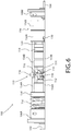
- an input shaft 102 and an output shaft 104 in a downhole application may be rotatably connected to each other by a transmission system 100.
- a CVT system 110 may be rotatably connected to input shaft 102 at a first or input end, and CVT system 110 may be rotatably connected to an intermediary output shaft 120 at a second or output end opposed to the first end of CVT 110.
- Intermediary output shaft 120 may thereby be rotatably connected to output shaft 104 in order to transitively connect input shaft 102 with output shaft 104 through transmission system 100.
- the input shaft 102, output shaft 104, CVT system 110, and intermediary output shaft 120 may be individually rotatable about a central axis 200 extending longitudinally through transmission system 100.
- Transmission system 100 may include a transmission housing 106 for covering or protecting the internal components of transmission system 100.
- transmission housing 106 is rotationally stable or secure while many of the internal or partially internal components, including input shaft 102, output shaft 104, CVT system 110, and intermediary output shaft 120 are freely rotatable.
- a housing end 108A may be provided on a first or input end of housing 106.
- a housing end 108B may also be provided on a second or output end of housing 106 for securing output shaft 102 with transmission system 100.
- Each housing end 108A, 108B may include any number of bearings 122 in order to permit the free rotation of input shaft 102 and output shaft 104 about central axis 200.
- transmission system 100 may have small dimensions. Some downhole applications, such as wireline tractors, may have small dimensions due to the narrowness of the hole and operating space. Embodiments of the transmission system 100 may be manufactured to accommodate small operating dimensions. For instance, one embodiment of transmission system 100 features a housing 106 with a diameter of approximately 4.6 cm (1.8 inches). In some embodiments the diameter of the housing 106 can be less than 8 cm (3 inches) in order to accommodate small downhole applications. Additionally, the longitudinal length of transmission system 100, measured from housing end 108A to housing end 108B, may be approximately 15 cm (6 inches) in one embodiment. In some embodiments, the length of transmission system 100 may be between 10 and 25 cm (4 and 10 inches).
- CVT system 110 may be a toroidal disc CVT system, as shown for instance in the illustrated embodiment, however other known or to be developed CVT systems for rotatably connecting input shaft 102 with intermediary output shaft 104 are contemplated within the disclosure. Illustrative CVT systems can include those that use balls, discs, and the like.
- Toroidal CVT system 110 may include a first or input rotating member 112, a second or output rotating member 114, and any number of toroidal discs 116 provided between first and second rotating members 112, 114.
- the toroidal discs 116 may be held between first and second rotating members 112, 114 by a disc arm 118. In the illustrated embodiment, two toroidal discs 116 are provided.
- CVT system 110 may operate to provide an infinite number of gear ratios between first and second rotating members 112, 114 depending on the position of the toroidal discs 116.
- the rolling or moving between gear positions of toroidal discs 116 may be accomplished in part by the swinging of disc arm 118.
- Each disc arm may be pivotally secured to a portion of system 110.
- a space or window 124 may be provided in housing 106 so that disc arm 118 will not contact or be interfered with by housing 106 as disc arm 118 swings between gears ratios.
- Fasteners 130 may be provided for securing input shaft 102 with first rotating member 112. The fasteners 130 may also be provided for securing intermediary output shaft 120 with second rotating member 114. Fasteners 130 may be bolts, screws or any other known or to be developed fastening devices.
- an output torque sensing control mechanism 150 may be integrated into transmission system 100.
- Output torque sensing control mechanism 150 may include a spring or other biasing member 152, arms or longitudinal members 154, and an intermediary output shaft housing 156.
- Intermediary output shaft housing 156 may be provided to secure intermediary output shaft 120 as well as to engage with the longitudinal members 154.
- Intermediary output shaft housing 156 may include a first portion 156A and a second portion 156B, each clampable together and including an aligned aperture for receiving a portion of intermediary output shaft 120 as well as output shaft 104.
- Bearings 122 may be provided between intermediary output shaft housing portions 156A, 156B and intermediary output shaft 120 in order to permit free rotation of intermediary output shaft 120.
- Intermediary output shaft 120 may also include wings 162 which extend away radially away from the intermediary output shaft 120, and at least a distal portion of wings 162 may be clamped by a pair of bearings 122 provided within intermediary output shaft housing 156.
- Intermediary output shaft 120 may be coupled to rotating member 114 at a first end, and connected with output shaft 104 at a second end.
- Intermediary output shaft 120 may include a bore 158 for receiving an end of output shaft 104. Bore 158 may be internally threaded while the end of output shaft 104 may be externally threaded and matable with the internal threading of bore 158.
- intermediary output shaft housing 156 and intermediary output shaft 120 may be operable to move or translate longitudinally along axis 200 as intermediary output shaft 120 is threaded onto output shaft 104. This threading operation enables output torque sensing control mechanism 150 to function as described herein, in accordance with the disclosure.
- spring 152 which may be coiled or wrapped about a portion of input shaft 102, may operate to provide a longitudinal translation force against intermediary output shaft housing 156 through arms 154.
- arms 154 are composed of a first arm 154A and a second arm 154B.
- First arm 154A may be provided between spring 152 and pivotable disc arm 118
- second arm 154B may be provided between the opposed side of pivotable disc arm 118 and intermediary output shaft housing 156, and connected to first intermediary output shaft housing portion 156A.
- the ends of first and second arms 154A, 154B, which contact pivotable disc arm 118 may be rounded so as to as to permit disc arm 118 to pivot or swing between gear ratios.
- First and second arms 154A, 154B may be provided between each disc arm 118 included in any particular embodiment.
- an intermediary disc 158 may be provided between spring 152 and arm 154.
- the pivotable disc arm may have a unique shape to mitigate or create a linear relationship to the gear ratio; for example, the pivotable disc arm 118 can have a shape to allow the disc arm 118 to maintain contact with the arm 154.
- a longitudinal rod 160 may be insertable through first and second rotating members 112, 114 along longitudinal axis 200. Bearings 122 may be provided on either end of rod 160 in order to permit the rod to freely rotate with respect to the CVT transmission 110.
- An output end 162 of rod 160 may be matable with intermediary output shaft 120 in order to permit mutual rotation of rod 160 and intermediary output shaft 120 when they are mated.
- the rod 160 can ensure that the first and second rotating members 112, 114 are in full compression, binding the toroidal disc 116.
- FIG. 7 illustrates a schematic of a downhole tractor having the transmission system of FIG.1 .
- a downhole tractor 700 includes a drive motor 300, input drive shaft 102, transmission system 100, and an output shaft 104 for driving wheels, grippers, or tracks (not shown) of the downhole tractor.
- the drive motor 300 may be connected to input drive shaft 102.
- the drive motor 300 can be a direct current motor or an alternating current motor.
- the drive motor 300 can be a three-phase motor.
- the input drive shaft 102 is connected to transmission system 100, comprising CVT 110 and output torque sensing control mechanism 150, which is connected to output shaft 104.
- Transmission system 100 may thus operate using the output torque sensing control mechanism 150 as a mechanism that determines how much torque is desired and mechanically adjusts the CVT 110 to provide the optimum results of the gear ratio.
- the CVT 110 may then operate as the mechanism that enables the gear ratio between the input shaft 102 and the output shaft 104 to be altered, for instance between 0.5:1 and 2.0:1 in accordance with one embodiment.
- FIGS. 8A-8E illustrate the functional concept of output torque sensing control mechanism 150 in accordance with one embodiment.
- FIGS. 8A-8D are sequentially ordered to illustrate the longitudinal translation, which occurs as rolling resistances are changed between a first end 400A of a shaft and a second end 400B of a shaft.
- second end 400B experiences an increase in rolling resistance from a previous equilibrium state.
- translation of the nut occurs due to its threadable engagement with the shaft.
- the nut stops once the rolling resistances 400A, 400B have reached an equilibrium.
- FIG. 8C the rolling resistance of 400B has decreased and, by operation of spring 152, the nut is translated back to equilibrium in FIG. 8D .
- input drive shaft is threaded on the end and screwed into an adjoining tubular output drive shaft
- the output shaft 104 may threaded on the end and screwed into an adjoining tubular shaft 158.
- the threading causes the threaded tubular shaft 158 to move with linear motion towards the threaded shaft 104.
- This linear motion can be mechanically linked to the CVT 110, for instance by contact between arms 154A, 154B and disc shafts 118.
- This matable threading of the shafts of output torque sensing control mechanism 150 can be variably designed to establish a relationship between the motor peak power setting and the output torque.
- a fine thread pitch may be utilized to offer greater mechanical leverage, while a coarser thread may be utilized to offer greater linear motion (which in embodiment where arms 154A, 154B are linked with disc shaft 118, may in turn offer greater maximum gear ratios for CVT 110 by increasing the maximum pitch angle of disc shaft 118).
- the shifting spring 152 may operate to move the tubular shaft back to a known position when no torque is applied by the output shaft. The known position would return the mechanically connected CVT 110 to a position where the gear ratio is less than 1; for example, the gear ratio can be about 0.5. This would happen, for instance, if the motor was turned off or experiencing minimal loading.
- transmission system 100 may be implemented with a wireline tractor.
- a motor spins a drive shaft that is connected to a series of gearboxes, which mechanically drive a wheel that is in contact with a downhole casing or borehole. Based on the amount of tractor force to be applied to convey or push payload services in horizontal environments, the desired torque may be outputted. Where gear ratios are fixed, and not variable, the tractors may be limited on downhole tractor speed by the amount of maximum expected applied torque or tractor force.
- CVT 110 allows the motor 300 under light torque loading to increase the overall drive shaft RPM, which thereby increases the forward tractor linear speed.
- the CVT 110 can be designed to ensure that as the torque loading increases the gear ratio is increased to reduce tractor speed and maintain the drive motor operating in the peak power position for highest efficiency.
- the highest efficiency position is factor to be considered as the demands on surface power supplies, limitations on electrical transmission through collectors and cables, and motor equipment safety may be considered.
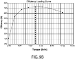
- FIGS. 9A and 9B graphic illustrations are provided to show attainable improved performance utilizing the disclosed transmission system in downhole applications.
- a tractor power curve downhole illustrates the relationship between tractor force (or load) and speed. As a drive motor speed increases, the tractor load capability decreases.
- the tractor power curve represents the fixed operating environment for known embodiments where it was previously impossible to go faster than 1.0668 kmph (3500 fph) or slower than 0.1524 kmph (500 fph).
- the speed may be further increased as shown by the extrapolated line, while maintaining the same or nearly the same motor power level.
- the gear ratio decreases more and more to allow the output shaft to spin fast while the motor rotations per minute stay at its maximum physical capability. Conversely, as the output shaft becomes more loaded, the gear ratio is increased which thereby slows the shaft, but increases the loading capacity. Essentially, the power curve becomes dynamic, which allows it to expand into operating envelopes that have been otherwise inaccessible due to downhole hardware limitations of fixed gear ratio systems.
- the transmission system 100 can be utilized to drive the loading to stay within a drive motor's peak power position. That is, the gear ratio can change in order to maintain maximum efficiency of a downhole motor for peak performance.
- the efficiency loading curve of FIG. 9B illustrates a peak efficiency, for one embodiment of a downhole application, at approximately 0.5649 N-m (5 lb-in). If the motor outputs any more or less loading, the loss of operating efficiency results in wasted energy.
- the variable gear ratio can be used to reduce or increase the motor torque to be the highest efficiency.
- An example of this in practice would be a downhole tractor conveying a tool in an openhole well.
- the load on the downhole tractor will change when washouts, obstructions, or other abnormalities are encountered, by utilizing transmission system 100, the gear ratio can continuously change to increase or decrease the amount of torque in order to maintain peak power efficiency through the various naturally occurring torque fluctuations of downhole conveyance.
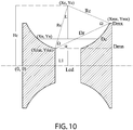
- FIG 10 illustrates a conceptualization of a toroidal disc CVT, which may be CVT 110 in embodiments of the disclosure.
- the toroidal disc illustrated on the left side is the input shaft while the toroidal disc on the right side is the output shaft. These discs are connected by a roller disc, labeled as D R .
- D R roller disc
- the D R disc touches the input shaft at point (X MN , Y MN ) and the output shaft at point (X MX , Y MX ).
- the gear ratio is created by the diameter D MX divided by D MN .
- the output torque sensing control mechanism 150 may be mechanically linked to the roller disc D R and creates the pivot motion. As illustrated in FIGS. 1-6 , this mechanical linkage may occur at arms 154A, 154B. By configuring the ends of arms 154A, 154B to be rounded, the disc D R is may freely pivot as arms 154 are longitudinally displaced. As output torque sensing control mechanism 150 demands more or less torque, a corresponding pivoting motion of the D R about (Xc, Yc) is created.
Landscapes
- Engineering & Computer Science (AREA)
- General Engineering & Computer Science (AREA)
- Mechanical Engineering (AREA)
- Mining & Mineral Resources (AREA)
- Life Sciences & Earth Sciences (AREA)
- Geology (AREA)
- Combustion & Propulsion (AREA)
- Chemical & Material Sciences (AREA)
- Fluid Mechanics (AREA)
- General Life Sciences & Earth Sciences (AREA)
- Geochemistry & Mineralogy (AREA)
- Environmental & Geological Engineering (AREA)
- Physics & Mathematics (AREA)
- Transportation (AREA)
- Friction Gearing (AREA)
Claims (5)
- Getriebesystem (100) zum drehbeweglichen Koppeln einer Eingangswelle (102) mit einer Ausgangswelle (104) um eine Längsachse zur Verwendung in einem Bohrloch-Traktor, wobei das Getriebe umfasst:ein stufenloses Getriebe (110), das umfasst: ein drehbar mit der Eingangswelle verbundenes Eingangsdrehglied; ein Ausgangsdrehglied; eine zwischen dem Eingangsdrehglied und dem Ausgangsdrehglied bereitgestellte Toroidscheibe; und einen mit der Toroidscheibe verbundenen Toroidscheibenarm, der ausgelegt ist, die Toroidscheibe zwischen mehreren Stellungen zwischen dem Eingangsdrehglied und dem Ausgangsdrehglied zu verschwenken; undeine Regelvorrichtung mit Ausgangsmomenterfassung (150), die umfasst: eine der Eingangswelle benachbart positionierte Feder; und eine drehbar mit dem Ausgangsdrehglied verbundene Zwischenausgangswelle, wobei die Zwischenausgangswelle einen mit einem Außengewindeabschnitt der Ausgangswelle zusammenpassend aufhehmbaren Innengewindeabschnitt aufweist, wobei die Zwischenausgangswelle in Längsrichtung beweglich ist, wenn die Zwischenausgangswelle mit der Ausgangswelle schraubend bewegt wird; ein Enden aufweisendes erstes Längsglied, das zwischen der Feder und dem Toroidscheibenarm bereitgestellt ist; und ein Enden aufweisendes zweites Längsglied, das zwischen dem Toroidscheibenarm und der Zwischenausgangswelle bereitgestellt ist.
- Getriebesystem nach Anspruch 1, wobei wenigstens ein Abschnitt der Ausgangswelle mit einem Außengewinde versehen ist, und die Regelvorrichtung mit Ausgangsmomenterfassung umfasst:eine Feder; undeine Zwischenausgangswelle, die einen mit einem Außengewindeabschnitt der Ausgangswelle zusammenpassend aufhehmbaren Innengewindeabschnitt aufweist, wobei die Zwischenausgangswelle in Längsrichtung beweglich ist, wenn die Zwischenausgangswelle mit der Ausgangswelle schraubend bewegt wird.
- Getriebesystem nach Anspruch 1, wobei die Feder um wenigstens einen Abschnitt der Eingangswelle herum bereitgestellt ist.
- Verfahren zum Transport im Bohrloch, das umfasst:Bereitstellen eines Bohrloch-Traktors, der umfasst:einen Motor,eine von dem Motor drehangetriebene Eingangswelle,ein mit der Eingangswelle verbundenes Getriebesystem, wobei das Getriebesystem umfasst:ein stufenloses Getriebe, das umfasst: ein drehbar mit der Eingangswelle verbundenes Eingangsdrehglied; ein Ausgangsdrehglied; eine zwischen dem Eingangsdrehglied und dem Ausgangsdrehglied bereitgestellte Toroidscheibe; und einen mit der Toroidscheibe verbundenen Toroidscheibenarm, der ausgelegt ist, die Toroidscheibe zwischen mehreren Stellungen zwischen dem Eingangsdrehglied und dem Ausgangsdrehglied zu verschwenken, undeine Regelvorrichtung mit Ausgangsmomenterfassung, die umfasst: eine der Eingangswelle benachbart positionierte Feder; und eine drehbar mit dem Ausgangsdrehglied verbundene Zwischenausgangswelle, wobei die Zwischenausgangswelle einen mit einem Außengewindeabschnitt einer mit dem Getriebesystem verbundenen Ausgangswelle zusammenpassend aufnehmbaren Innengewindeabschnitt aufweist, wobei die Zwischenausgangswelle in Längsrichtung beweglich ist, wenn die Zwischenausgangswelle mit der Ausgangswelle schraubend bewegt wird; ein Enden aufweisendes erstes Längsglied, das zwischen der Feder und dem Toroidscheibenarm bereitgestellt ist; und ein Enden aufweisendes zweites Längsglied, das zwischen dem Toroidscheibenarm und der Zwischenausgangswelle bereitgestellt ist; undeinen mit der Ausgangswelle verbundenen Bohrloch-Traktor;Einsetzen des Bohrloch-Traktors, der Ausgangswelle und des Getriebesystems in ein Loch;und Betreiben des Motors, wodurch der Bohrloch-Traktor angetrieben wird.
- Verfahren nach Anspruch 4, das ferner umfasst, das Getriebesystem, die Ausgangswelle und den Bohrloch-Traktor horizontal zur Erde auszurichten, um Bohrlochmessungen mit einem in Funktionsverbindung mit dem Bohrloch-Traktor verbundenen Bohrlochmessgerät durchzuführen.
Applications Claiming Priority (1)
| Application Number | Priority Date | Filing Date | Title |
|---|---|---|---|
| US14/054,386 US9115793B2 (en) | 2013-10-15 | 2013-10-15 | Controllable mechanical transmission for downhole applications |
Publications (3)
| Publication Number | Publication Date |
|---|---|
| EP2863002A2 EP2863002A2 (de) | 2015-04-22 |
| EP2863002A3 EP2863002A3 (de) | 2016-01-06 |
| EP2863002B1 true EP2863002B1 (de) | 2018-06-27 |
Family
ID=51703057
Family Applications (1)
| Application Number | Title | Priority Date | Filing Date |
|---|---|---|---|
| EP14189071.5A Not-in-force EP2863002B1 (de) | 2013-10-15 | 2014-10-15 | Steuerbares mechanisches Getriebe für Bohrlochanwendungen |
Country Status (2)
| Country | Link |
|---|---|
| US (2) | US9115793B2 (de) |
| EP (1) | EP2863002B1 (de) |
Families Citing this family (4)
| Publication number | Priority date | Publication date | Assignee | Title |
|---|---|---|---|---|
| CN105793513B (zh) * | 2013-12-23 | 2018-06-22 | 哈里伯顿能源服务公司 | 钻柱部分旋转速度的独立修改 |
| CN106323676A (zh) * | 2016-08-19 | 2017-01-11 | 王启先 | 一种太阳能供电的地质样品取样装置 |
| US10385657B2 (en) | 2016-08-30 | 2019-08-20 | General Electric Company | Electromagnetic well bore robot conveyance system |
| NO20240502A1 (en) * | 2024-05-16 | 2025-11-17 | Pipesnake As | A tractor for propelling an apparatus inside a cylindrical body |
Family Cites Families (24)
| Publication number | Priority date | Publication date | Assignee | Title |
|---|---|---|---|---|
| US1139433A (en) * | 1912-11-18 | 1915-05-11 | Arthur R Monro | Automatically-variable gearing. |
| US1629902A (en) * | 1924-08-07 | 1927-05-24 | Arter Jakob | Power-transmitting device |
| US1772593A (en) * | 1928-04-10 | 1930-08-12 | Robertson John Hogg | Friction gearing |
| US1880217A (en) * | 1929-10-22 | 1932-10-04 | Richard P Simmons | Motor driven well drilling apparatus |
| US2030203A (en) * | 1934-05-31 | 1936-02-11 | Gen Motors Corp | Torque loading lash adjusting device for friction roller transmissions |
| US2108083A (en) * | 1934-08-25 | 1938-02-15 | John S Sharpe | Transmission mechanism |
| US2445066A (en) * | 1946-10-22 | 1948-07-13 | Frank A Hayes | Thrust sustaining means for variable speed drive mechanism |
| US2588408A (en) * | 1947-05-08 | 1952-03-11 | Charles M O'leary | Oil well drilling transmission |
| US2743084A (en) * | 1952-09-10 | 1956-04-24 | Arutunoff Armais | Drilling apparatus with sedimentation reservoir |
| US2822148A (en) * | 1954-02-23 | 1958-02-04 | Robert W Murray | Electric boring apparatus |
| US2711655A (en) * | 1954-05-13 | 1955-06-28 | Roller Gear Company Inc | Ball bearing screw device |
| US2959063A (en) * | 1956-09-11 | 1960-11-08 | Perbury Engineering Ltd | Infinitely variable change speed gears |
| US3033048A (en) * | 1958-01-09 | 1962-05-08 | Fabrications Unicum Soc D | Power transmission devices |
| US3048056A (en) * | 1958-04-10 | 1962-08-07 | Gen Motors Corp | Drive system |
| US2949800A (en) * | 1959-05-11 | 1960-08-23 | Neuschotz Robert | Tool for installing threaded elements |
| US3183741A (en) * | 1963-04-11 | 1965-05-18 | Lucas Industries Ltd | Variable speed power transmission mechanism |
| US3184983A (en) * | 1963-10-30 | 1965-05-25 | Excelermatic | Toroidal transmission mechanism with torque loading cam means |
| JPS521048B2 (de) * | 1973-09-01 | 1977-01-12 | ||
| JP2578448Y2 (ja) * | 1992-03-13 | 1998-08-13 | 日産自動車株式会社 | ローディングカム装置 |
| US5170852A (en) * | 1992-05-11 | 1992-12-15 | Nitto Seiko Co., Ltd. | Automatic screw fastening machine |
| CN101526127B (zh) * | 2001-04-26 | 2011-08-17 | 瀑溪技术公司 | 连续可变变速器及部件支撑件、支撑框架及框架制作方法 |
| CA2523092C (en) * | 2003-04-25 | 2012-10-23 | Stuart Schaaf | Systems and methods using a continuously variable transmission to control one or more system components |
| US8033328B2 (en) * | 2004-11-05 | 2011-10-11 | Schlumberger Technology Corporation | Downhole electric power generator |
| EP1811202A1 (de) * | 2005-12-30 | 2007-07-25 | Fallbrook Technologies, Inc. | Stufenloses Getriebe |
-
2013
- 2013-10-15 US US14/054,386 patent/US9115793B2/en not_active Expired - Fee Related
-
2014
- 2014-10-15 EP EP14189071.5A patent/EP2863002B1/de not_active Not-in-force
-
2015
- 2015-08-06 US US14/820,394 patent/US20150345598A1/en not_active Abandoned
Non-Patent Citations (1)
| Title |
|---|
| None * |
Also Published As
| Publication number | Publication date |
|---|---|
| US20150105219A1 (en) | 2015-04-16 |
| US9115793B2 (en) | 2015-08-25 |
| EP2863002A3 (de) | 2016-01-06 |
| EP2863002A2 (de) | 2015-04-22 |
| US20150345598A1 (en) | 2015-12-03 |
Similar Documents
| Publication | Publication Date | Title |
|---|---|---|
| EP0811111B1 (de) | Bohrlochwerkzeug | |
| US8827856B1 (en) | Infinitely variable transmission with an IVT stator controlling assembly | |
| US9115793B2 (en) | Controllable mechanical transmission for downhole applications | |
| CN1791731B (zh) | 使用连续可变传动装置来控制一个或多个系统部件的系统和方法 | |
| US9890602B2 (en) | Well runner | |
| US12000458B2 (en) | Reversible variable drives and systems and methods for control in forward and reverse directions | |
| US11008809B2 (en) | Bent housing drilling motor with counter-rotating lower end | |
| AU2016266082A1 (en) | Well tractor | |
| US20150108767A1 (en) | Constant velocity device for downhole power generation | |
| CN107002830B (zh) | 基于具有螺旋齿状过渡部分的齿轮传动装置 | |
| US6053840A (en) | Gear transmission with automatic continuously variable mechanical advantage | |
| CN1890488A (zh) | 改进的无级变速器装置 | |
| CA2726969C (en) | Systems and methods using a continuously variable transmission to control one or more system components | |
| GB2363811A (en) | Steerable drilling tool | |
| US6910984B1 (en) | Positive engagement continuously variable transmission | |
| NO20240502A1 (en) | A tractor for propelling an apparatus inside a cylindrical body | |
| HK1093360B (en) | Systems and methods using a continuously variable transmission to control one or more system components | |
| MXPA97006335A (en) | Tool located in the fund of the perforac |
Legal Events
| Date | Code | Title | Description |
|---|---|---|---|
| PUAI | Public reference made under article 153(3) epc to a published international application that has entered the european phase |
Free format text: ORIGINAL CODE: 0009012 |
|
| 17P | Request for examination filed |
Effective date: 20141015 |
|
| AK | Designated contracting states |
Kind code of ref document: A2 Designated state(s): AL AT BE BG CH CY CZ DE DK EE ES FI FR GB GR HR HU IE IS IT LI LT LU LV MC MK MT NL NO PL PT RO RS SE SI SK SM TR |
|
| AX | Request for extension of the european patent |
Extension state: BA ME |
|
| PUAL | Search report despatched |
Free format text: ORIGINAL CODE: 0009013 |
|
| AK | Designated contracting states |
Kind code of ref document: A3 Designated state(s): AL AT BE BG CH CY CZ DE DK EE ES FI FR GB GR HR HU IE IS IT LI LT LU LV MC MK MT NL NO PL PT RO RS SE SI SK SM TR |
|
| AX | Request for extension of the european patent |
Extension state: BA ME |
|
| RIC1 | Information provided on ipc code assigned before grant |
Ipc: E21B 4/00 20060101ALI20151130BHEP Ipc: E21B 3/02 20060101AFI20151130BHEP |
|
| RAP1 | Party data changed (applicant data changed or rights of an application transferred) |
Owner name: SCHLUMBERGER HOLDINGS LIMITED Owner name: SCHLUMBERGER TECHNOLOGY B.V. (STBV) Owner name: SERVICES PETROLIERS SCHLUMBERGER |
|
| GRAP | Despatch of communication of intention to grant a patent |
Free format text: ORIGINAL CODE: EPIDOSNIGR1 |
|
| INTG | Intention to grant announced |
Effective date: 20170925 |
|
| GRAS | Grant fee paid |
Free format text: ORIGINAL CODE: EPIDOSNIGR3 |
|
| GRAJ | Information related to disapproval of communication of intention to grant by the applicant or resumption of examination proceedings by the epo deleted |
Free format text: ORIGINAL CODE: EPIDOSDIGR1 |
|
| GRAL | Information related to payment of fee for publishing/printing deleted |
Free format text: ORIGINAL CODE: EPIDOSDIGR3 |
|
| GRAP | Despatch of communication of intention to grant a patent |
Free format text: ORIGINAL CODE: EPIDOSNIGR1 |
|
| INTC | Intention to grant announced (deleted) | ||
| INTG | Intention to grant announced |
Effective date: 20180108 |
|
| GRAA | (expected) grant |
Free format text: ORIGINAL CODE: 0009210 |
|
| AK | Designated contracting states |
Kind code of ref document: B1 Designated state(s): AL AT BE BG CH CY CZ DE DK EE ES FI FR GB GR HR HU IE IS IT LI LT LU LV MC MK MT NL NO PL PT RO RS SE SI SK SM TR |
|
| REG | Reference to a national code |
Ref country code: GB Ref legal event code: FG4D |
|
| REG | Reference to a national code |
Ref country code: AT Ref legal event code: REF Ref document number: 1012519 Country of ref document: AT Kind code of ref document: T Effective date: 20180715 |
|
| REG | Reference to a national code |
Ref country code: DE Ref legal event code: R096 Ref document number: 602014027469 Country of ref document: DE |
|
| REG | Reference to a national code |
Ref country code: IE Ref legal event code: FG4D |
|
| PG25 | Lapsed in a contracting state [announced via postgrant information from national office to epo] |
Ref country code: SE Free format text: LAPSE BECAUSE OF FAILURE TO SUBMIT A TRANSLATION OF THE DESCRIPTION OR TO PAY THE FEE WITHIN THE PRESCRIBED TIME-LIMIT Effective date: 20180627 Ref country code: FI Free format text: LAPSE BECAUSE OF FAILURE TO SUBMIT A TRANSLATION OF THE DESCRIPTION OR TO PAY THE FEE WITHIN THE PRESCRIBED TIME-LIMIT Effective date: 20180627 Ref country code: BG Free format text: LAPSE BECAUSE OF FAILURE TO SUBMIT A TRANSLATION OF THE DESCRIPTION OR TO PAY THE FEE WITHIN THE PRESCRIBED TIME-LIMIT Effective date: 20180927 Ref country code: LT Free format text: LAPSE BECAUSE OF FAILURE TO SUBMIT A TRANSLATION OF THE DESCRIPTION OR TO PAY THE FEE WITHIN THE PRESCRIBED TIME-LIMIT Effective date: 20180627 |
|
| REG | Reference to a national code |
Ref country code: NL Ref legal event code: MP Effective date: 20180627 |
|
| REG | Reference to a national code |
Ref country code: LT Ref legal event code: MG4D Ref country code: NO Ref legal event code: T2 Effective date: 20180627 |
|
| PG25 | Lapsed in a contracting state [announced via postgrant information from national office to epo] |
Ref country code: GR Free format text: LAPSE BECAUSE OF FAILURE TO SUBMIT A TRANSLATION OF THE DESCRIPTION OR TO PAY THE FEE WITHIN THE PRESCRIBED TIME-LIMIT Effective date: 20180928 Ref country code: HR Free format text: LAPSE BECAUSE OF FAILURE TO SUBMIT A TRANSLATION OF THE DESCRIPTION OR TO PAY THE FEE WITHIN THE PRESCRIBED TIME-LIMIT Effective date: 20180627 Ref country code: LV Free format text: LAPSE BECAUSE OF FAILURE TO SUBMIT A TRANSLATION OF THE DESCRIPTION OR TO PAY THE FEE WITHIN THE PRESCRIBED TIME-LIMIT Effective date: 20180627 Ref country code: RS Free format text: LAPSE BECAUSE OF FAILURE TO SUBMIT A TRANSLATION OF THE DESCRIPTION OR TO PAY THE FEE WITHIN THE PRESCRIBED TIME-LIMIT Effective date: 20180627 |
|
| PGFP | Annual fee paid to national office [announced via postgrant information from national office to epo] |
Ref country code: GB Payment date: 20180927 Year of fee payment: 5 |
|
| REG | Reference to a national code |
Ref country code: AT Ref legal event code: MK05 Ref document number: 1012519 Country of ref document: AT Kind code of ref document: T Effective date: 20180627 |
|
| PG25 | Lapsed in a contracting state [announced via postgrant information from national office to epo] |
Ref country code: NL Free format text: LAPSE BECAUSE OF FAILURE TO SUBMIT A TRANSLATION OF THE DESCRIPTION OR TO PAY THE FEE WITHIN THE PRESCRIBED TIME-LIMIT Effective date: 20180627 |
|
| PG25 | Lapsed in a contracting state [announced via postgrant information from national office to epo] |
Ref country code: RO Free format text: LAPSE BECAUSE OF FAILURE TO SUBMIT A TRANSLATION OF THE DESCRIPTION OR TO PAY THE FEE WITHIN THE PRESCRIBED TIME-LIMIT Effective date: 20180627 Ref country code: CZ Free format text: LAPSE BECAUSE OF FAILURE TO SUBMIT A TRANSLATION OF THE DESCRIPTION OR TO PAY THE FEE WITHIN THE PRESCRIBED TIME-LIMIT Effective date: 20180627 Ref country code: EE Free format text: LAPSE BECAUSE OF FAILURE TO SUBMIT A TRANSLATION OF THE DESCRIPTION OR TO PAY THE FEE WITHIN THE PRESCRIBED TIME-LIMIT Effective date: 20180627 Ref country code: AT Free format text: LAPSE BECAUSE OF FAILURE TO SUBMIT A TRANSLATION OF THE DESCRIPTION OR TO PAY THE FEE WITHIN THE PRESCRIBED TIME-LIMIT Effective date: 20180627 Ref country code: IS Free format text: LAPSE BECAUSE OF FAILURE TO SUBMIT A TRANSLATION OF THE DESCRIPTION OR TO PAY THE FEE WITHIN THE PRESCRIBED TIME-LIMIT Effective date: 20181027 Ref country code: PL Free format text: LAPSE BECAUSE OF FAILURE TO SUBMIT A TRANSLATION OF THE DESCRIPTION OR TO PAY THE FEE WITHIN THE PRESCRIBED TIME-LIMIT Effective date: 20180627 Ref country code: SK Free format text: LAPSE BECAUSE OF FAILURE TO SUBMIT A TRANSLATION OF THE DESCRIPTION OR TO PAY THE FEE WITHIN THE PRESCRIBED TIME-LIMIT Effective date: 20180627 |
|
| PGFP | Annual fee paid to national office [announced via postgrant information from national office to epo] |
Ref country code: NO Payment date: 20180928 Year of fee payment: 5 |
|
| PG25 | Lapsed in a contracting state [announced via postgrant information from national office to epo] |
Ref country code: SM Free format text: LAPSE BECAUSE OF FAILURE TO SUBMIT A TRANSLATION OF THE DESCRIPTION OR TO PAY THE FEE WITHIN THE PRESCRIBED TIME-LIMIT Effective date: 20180627 Ref country code: IT Free format text: LAPSE BECAUSE OF FAILURE TO SUBMIT A TRANSLATION OF THE DESCRIPTION OR TO PAY THE FEE WITHIN THE PRESCRIBED TIME-LIMIT Effective date: 20180627 Ref country code: ES Free format text: LAPSE BECAUSE OF FAILURE TO SUBMIT A TRANSLATION OF THE DESCRIPTION OR TO PAY THE FEE WITHIN THE PRESCRIBED TIME-LIMIT Effective date: 20180627 |
|
| REG | Reference to a national code |
Ref country code: DE Ref legal event code: R097 Ref document number: 602014027469 Country of ref document: DE |
|
| REG | Reference to a national code |
Ref country code: DE Ref legal event code: R119 Ref document number: 602014027469 Country of ref document: DE |
|
| PLBE | No opposition filed within time limit |
Free format text: ORIGINAL CODE: 0009261 |
|
| STAA | Information on the status of an ep patent application or granted ep patent |
Free format text: STATUS: NO OPPOSITION FILED WITHIN TIME LIMIT |
|
| PG25 | Lapsed in a contracting state [announced via postgrant information from national office to epo] |
Ref country code: DK Free format text: LAPSE BECAUSE OF FAILURE TO SUBMIT A TRANSLATION OF THE DESCRIPTION OR TO PAY THE FEE WITHIN THE PRESCRIBED TIME-LIMIT Effective date: 20180627 |
|
| REG | Reference to a national code |
Ref country code: CH Ref legal event code: PL |
|
| 26N | No opposition filed |
Effective date: 20190328 |
|
| REG | Reference to a national code |
Ref country code: BE Ref legal event code: MM Effective date: 20181031 |
|
| PG25 | Lapsed in a contracting state [announced via postgrant information from national office to epo] |
Ref country code: LU Free format text: LAPSE BECAUSE OF NON-PAYMENT OF DUE FEES Effective date: 20181015 Ref country code: MC Free format text: LAPSE BECAUSE OF FAILURE TO SUBMIT A TRANSLATION OF THE DESCRIPTION OR TO PAY THE FEE WITHIN THE PRESCRIBED TIME-LIMIT Effective date: 20180627 |
|
| REG | Reference to a national code |
Ref country code: IE Ref legal event code: MM4A |
|
| PG25 | Lapsed in a contracting state [announced via postgrant information from national office to epo] |
Ref country code: DE Free format text: LAPSE BECAUSE OF NON-PAYMENT OF DUE FEES Effective date: 20190501 |
|
| PG25 | Lapsed in a contracting state [announced via postgrant information from national office to epo] |
Ref country code: LI Free format text: LAPSE BECAUSE OF NON-PAYMENT OF DUE FEES Effective date: 20181031 Ref country code: CH Free format text: LAPSE BECAUSE OF NON-PAYMENT OF DUE FEES Effective date: 20181031 Ref country code: FR Free format text: LAPSE BECAUSE OF NON-PAYMENT OF DUE FEES Effective date: 20181031 Ref country code: BE Free format text: LAPSE BECAUSE OF NON-PAYMENT OF DUE FEES Effective date: 20181031 Ref country code: SI Free format text: LAPSE BECAUSE OF FAILURE TO SUBMIT A TRANSLATION OF THE DESCRIPTION OR TO PAY THE FEE WITHIN THE PRESCRIBED TIME-LIMIT Effective date: 20180627 |
|
| PG25 | Lapsed in a contracting state [announced via postgrant information from national office to epo] |
Ref country code: IE Free format text: LAPSE BECAUSE OF NON-PAYMENT OF DUE FEES Effective date: 20181015 |
|
| PG25 | Lapsed in a contracting state [announced via postgrant information from national office to epo] |
Ref country code: AL Free format text: LAPSE BECAUSE OF FAILURE TO SUBMIT A TRANSLATION OF THE DESCRIPTION OR TO PAY THE FEE WITHIN THE PRESCRIBED TIME-LIMIT Effective date: 20180627 |
|
| PG25 | Lapsed in a contracting state [announced via postgrant information from national office to epo] |
Ref country code: MT Free format text: LAPSE BECAUSE OF NON-PAYMENT OF DUE FEES Effective date: 20181015 |
|
| PG25 | Lapsed in a contracting state [announced via postgrant information from national office to epo] |
Ref country code: TR Free format text: LAPSE BECAUSE OF FAILURE TO SUBMIT A TRANSLATION OF THE DESCRIPTION OR TO PAY THE FEE WITHIN THE PRESCRIBED TIME-LIMIT Effective date: 20180627 |
|
| REG | Reference to a national code |
Ref country code: NO Ref legal event code: MMEP |
|
| PG25 | Lapsed in a contracting state [announced via postgrant information from national office to epo] |
Ref country code: PT Free format text: LAPSE BECAUSE OF FAILURE TO SUBMIT A TRANSLATION OF THE DESCRIPTION OR TO PAY THE FEE WITHIN THE PRESCRIBED TIME-LIMIT Effective date: 20180627 |
|
| PG25 | Lapsed in a contracting state [announced via postgrant information from national office to epo] |
Ref country code: HU Free format text: LAPSE BECAUSE OF FAILURE TO SUBMIT A TRANSLATION OF THE DESCRIPTION OR TO PAY THE FEE WITHIN THE PRESCRIBED TIME-LIMIT; INVALID AB INITIO Effective date: 20141015 Ref country code: MK Free format text: LAPSE BECAUSE OF NON-PAYMENT OF DUE FEES Effective date: 20180627 Ref country code: CY Free format text: LAPSE BECAUSE OF FAILURE TO SUBMIT A TRANSLATION OF THE DESCRIPTION OR TO PAY THE FEE WITHIN THE PRESCRIBED TIME-LIMIT Effective date: 20180627 |
|
| PG25 | Lapsed in a contracting state [announced via postgrant information from national office to epo] |
Ref country code: NO Free format text: LAPSE BECAUSE OF NON-PAYMENT OF DUE FEES Effective date: 20191031 |
|
| GBPC | Gb: european patent ceased through non-payment of renewal fee |
Effective date: 20191015 |
|
| PG25 | Lapsed in a contracting state [announced via postgrant information from national office to epo] |
Ref country code: GB Free format text: LAPSE BECAUSE OF NON-PAYMENT OF DUE FEES Effective date: 20191015 |
|
| P01 | Opt-out of the competence of the unified patent court (upc) registered |
Effective date: 20231208 |