EP2862801A1 - Integral clamp hubcap for wheel system and apparatus - Google Patents
Integral clamp hubcap for wheel system and apparatus Download PDFInfo
- Publication number
- EP2862801A1 EP2862801A1 EP20140170781 EP14170781A EP2862801A1 EP 2862801 A1 EP2862801 A1 EP 2862801A1 EP 20140170781 EP20140170781 EP 20140170781 EP 14170781 A EP14170781 A EP 14170781A EP 2862801 A1 EP2862801 A1 EP 2862801A1
- Authority
- EP
- European Patent Office
- Prior art keywords
- hubcap
- clamp
- wheel
- assembly
- retaining device
- Prior art date
- Legal status (The legal status is an assumption and is not a legal conclusion. Google has not performed a legal analysis and makes no representation as to the accuracy of the status listed.)
- Withdrawn
Links
- 239000000853 adhesive Substances 0.000 claims description 5
- 230000001070 adhesive effect Effects 0.000 claims description 5
- 230000008878 coupling Effects 0.000 abstract description 5
- 238000010168 coupling process Methods 0.000 abstract description 5
- 238000005859 coupling reaction Methods 0.000 abstract description 5
- 238000000034 method Methods 0.000 description 9
- 230000007246 mechanism Effects 0.000 description 8
- 230000008901 benefit Effects 0.000 description 6
- 238000012423 maintenance Methods 0.000 description 5
- 239000000463 material Substances 0.000 description 4
- 230000000717 retained effect Effects 0.000 description 3
- 230000000712 assembly Effects 0.000 description 2
- 238000000429 assembly Methods 0.000 description 2
- 229910052751 metal Inorganic materials 0.000 description 2
- 239000002184 metal Substances 0.000 description 2
- 206010070245 Foreign body Diseases 0.000 description 1
- 239000004677 Nylon Substances 0.000 description 1
- 229910000831 Steel Inorganic materials 0.000 description 1
- RTAQQCXQSZGOHL-UHFFFAOYSA-N Titanium Chemical compound [Ti] RTAQQCXQSZGOHL-UHFFFAOYSA-N 0.000 description 1
- 229910045601 alloy Inorganic materials 0.000 description 1
- 239000000956 alloy Substances 0.000 description 1
- 229910052782 aluminium Inorganic materials 0.000 description 1
- XAGFODPZIPBFFR-UHFFFAOYSA-N aluminium Chemical compound [Al] XAGFODPZIPBFFR-UHFFFAOYSA-N 0.000 description 1
- 239000002131 composite material Substances 0.000 description 1
- 238000010586 diagram Methods 0.000 description 1
- 230000014759 maintenance of location Effects 0.000 description 1
- 229920001778 nylon Polymers 0.000 description 1
- 229920000642 polymer Polymers 0.000 description 1
- 239000010959 steel Substances 0.000 description 1
- 239000000126 substance Substances 0.000 description 1
- 239000010936 titanium Substances 0.000 description 1
- 229910052719 titanium Inorganic materials 0.000 description 1
Images



Classifications
-
- B—PERFORMING OPERATIONS; TRANSPORTING
- B60—VEHICLES IN GENERAL
- B60B—VEHICLE WHEELS; CASTORS; AXLES FOR WHEELS OR CASTORS; INCREASING WHEEL ADHESION
- B60B7/00—Wheel cover discs, rings, or the like, for ornamenting, protecting, venting, or obscuring, wholly or in part, the wheel body, rim, hub, or tyre sidewall, e.g. wheel cover discs, wheel cover discs with cooling fins
- B60B7/06—Fastening arrangements therefor
- B60B7/10—Fastening arrangements therefor comprising a plurality of spaced spring clips individually mounted on the cover, e.g. riveted, welded or readily releasable
-
- B—PERFORMING OPERATIONS; TRANSPORTING
- B60—VEHICLES IN GENERAL
- B60B—VEHICLE WHEELS; CASTORS; AXLES FOR WHEELS OR CASTORS; INCREASING WHEEL ADHESION
- B60B7/00—Wheel cover discs, rings, or the like, for ornamenting, protecting, venting, or obscuring, wholly or in part, the wheel body, rim, hub, or tyre sidewall, e.g. wheel cover discs, wheel cover discs with cooling fins
- B60B7/04—Wheel cover discs, rings, or the like, for ornamenting, protecting, venting, or obscuring, wholly or in part, the wheel body, rim, hub, or tyre sidewall, e.g. wheel cover discs, wheel cover discs with cooling fins built-up of several main parts
-
- B—PERFORMING OPERATIONS; TRANSPORTING
- B60—VEHICLES IN GENERAL
- B60B—VEHICLE WHEELS; CASTORS; AXLES FOR WHEELS OR CASTORS; INCREASING WHEEL ADHESION
- B60B7/00—Wheel cover discs, rings, or the like, for ornamenting, protecting, venting, or obscuring, wholly or in part, the wheel body, rim, hub, or tyre sidewall, e.g. wheel cover discs, wheel cover discs with cooling fins
- B60B7/0013—Hub caps
-
- B—PERFORMING OPERATIONS; TRANSPORTING
- B60—VEHICLES IN GENERAL
- B60B—VEHICLE WHEELS; CASTORS; AXLES FOR WHEELS OR CASTORS; INCREASING WHEEL ADHESION
- B60B7/00—Wheel cover discs, rings, or the like, for ornamenting, protecting, venting, or obscuring, wholly or in part, the wheel body, rim, hub, or tyre sidewall, e.g. wheel cover discs, wheel cover discs with cooling fins
- B60B7/06—Fastening arrangements therefor
- B60B7/061—Fastening arrangements therefor characterised by the part of the wheels to which the discs, rings or the like are mounted
- B60B7/063—Fastening arrangements therefor characterised by the part of the wheels to which the discs, rings or the like are mounted to the rim
-
- B—PERFORMING OPERATIONS; TRANSPORTING
- B64—AIRCRAFT; AVIATION; COSMONAUTICS
- B64C—AEROPLANES; HELICOPTERS
- B64C25/00—Alighting gear
- B64C25/32—Alighting gear characterised by elements which contact the ground or similar surface
- B64C25/34—Alighting gear characterised by elements which contact the ground or similar surface wheeled type, e.g. multi-wheeled bogies
- B64C25/36—Arrangements or adaptations of wheels, tyres or axles in general
Definitions
- the present disclosure relates to wheel hubcaps and, more specifically, to an integral clamp hubcap for retention of the hubcap on a wheel.
- Aircraft wheels may include a hubcap that is retained on the wheel with a retaining device such as a clamp. During maintenance operations the hubcap and retaining device may be removed to service and/or to remove the wheel. When removed, the hubcap and retaining device may be separate pieces that may be misplaced, increasing the risk of foreign object damage ("FOD”) and/or requiring replacement after loss.
- FOD foreign object damage
- a hubcap assembly may comprise a hubcap, a clamp and a retaining device.
- the retaining device may be configured to connect the hubcap and the clamp.
- a wheel assembly may comprise an aircraft wheel, a hubcap, a clamp, and a retaining device.
- the hubcap may be installable on the aircraft wheel.
- the clamp may be configured to engage the wheel and the hubcap.
- the retaining device may be fixedly attached to the hubcap and the clamp.
- a clamp assembly comprises a clamp and a retaining device.
- the retaining device may be attached to the clamp.
- the retaining device may also be configured to couple to a hubcap.
- the retaining device may be configured to pass through the clamp and engage the hubcap.
- any reference to singular includes plural embodiments, and any reference to more than one component or step may include a singular embodiment or step.
- Vehicles that comprise wheels often include hubcaps that protect internal rotating components in the wheel, such as for example, bearings, bushings, and/or the like.
- the hubcap may be retained by a clamp that ties, couples and/or otherwise clamps the hubcap to the wheel.
- the hubcap and clamp may be removed to perform maintenance operations and/or the like. During these maintenance operations the clamp and/or hubcap are removed and place aside (e.g., set on the ground so that a technician may access the wheel or other structures to conduct the maintenance operation).
- the clamp may be any suitable structure, shape, and/or configuration suitable for retaining a hubcap on a wheel.
- the clamp may be a v-clamp (e.g., a clamp having a substantially "v" shaped portion), a u-clamp (e.g., a clamp having a substantially "u” shaped portion), an o-clamp, a u-bolt (e.g., a bolt having a substantially "u” shaped portion), a band clamp, an asymmetric clamp, and/or the like.
- the retaining devices described herein provide cost effective, reliable, and efficient mechanisms for creating hubcap/clamp assemblies.
- the clamp and hubcap may be coupled or fixed together to form an assembly.
- the assembly is less likely to be lost or displaced (e.g., kicked) during a maintenance operation, which reduces the risk of FOD in an aircraft operating environment.
- the assembly may be provided as a single line-replaceable unit ("LRU"), as opposed to multiple LRUs (e.g., for the clamp and hubcap, separately).
- LRU line-replaceable unit
- a vehicle such as an aircraft may comprise landing gear or a drive train with a wheel 110 and a hubcap 120.
- Hubcap 120 may be installable on wheel 110.
- Hubcap 120 may be retained and/or secured to wheel 110 with a clamp 130.
- Hubcap 120 and clamp 130 may be coupled to one another by a retaining device 140.
- retaining device 140 may be any suitable structure that is capable of coupling, attaching, securing and/or otherwise joining hubcap 120 and clamp 130.
- retaining device 140 may be a tab, a cable, a bond (e.g., a weld, a braze, an adhesive, and/or the like), a fastener (e.g., a screw, rivet, pin, and/or the like), and/or a bracket.
- clamp 230 may have a generally circular shape.
- Clamp 230 may have free ends (e.g., a first free end 231 and a second free end 233) that couple to one another when installed on wheel 110, as shown in FIG. 1 , and/or hubcap 220.
- Free ends 231 and 233 may be coupled and/or held together with a coupling mechanism 232.
- first free end 231 may comprise a bolt and second free end 233 may receive a nut (e.g., coupling mechanism 232 comprises a bolt and a nut).
- the bolt may be coupled to the nut to secure first free end 231 to the second free end 233, and similarly, secure and/or couple hubcap 220 to a wheel.
- a retaining mechanism such as retaining mechanisms 240A through 240C may affix and/or fixedly attach clamp 230 to hubcap 220.
- retaining mechanisms 240A through 240C may be fixedly attached to both clamp 230 and hubcap 220, but may allow movement between clamp 230 and hubcap 220 (e.g., where the retaining device is a wire or cable).
- Retaining mechanisms 240A through 240C may be installed at any suitable location of clamp 230 and/or hubcap 220.
- retaining mechanisms 240A through 240C may be installed along a portion of the generally circular diameter such that free ends 231 and 233 are able to move sufficiently to surround the wheel diameter when the clamp 230/hubcap 220 assembly is installed on the wheel.
- the retaining device may be a tab 240A.
- Tab 240A may comprise a first end 241 A and a second end 243A.
- the first end 241A may be attached to clamp 230 and the second end 243A may be attached to hubcap 220.
- the first end 241A may be attached with a fastener or bond.
- the second end 243A may be attached with a fastener or bond.
- the retaining device may comprise cable 240B (e.g., a wire, cord and/or the like).
- Cable 240B may comprise a first end 241B and a second end 243B.
- the first end 241B may be attached to clamp 230 and the second end 243B may be attached to hubcap 220.
- the first end 241B may be attached with a fastener or bond.
- the second end 243B may be attached with a fastener or bond.
- Cable 240B may be any suitable materials such as for example, a metal (e.g., aluminum, steel, titanium, and/or any other suitable metal or alloy), a polymer (e.g., nylon), a composite, and/or any other suitable material.
- the retaining device may be a bond 240C.
- Bond 240C may be a weld, braze, adhesive and/or the like bonding hubcap 220 to clamp 230.
- bond 240C may couple and/or attach hubcap 220 to at least a portion of clamp 230.
- the retaining device may be a fastener 340D.
- Fastener 340D may be screw, rivet, pin, and/or the like.
- fastener 340D may be configured to pass through a portion (such as an opening) of clamp 330 and engage hubcap 320.
- fastener 340D may be configured to pass through a portion of hubcap 320 and engage clamp 330.
- fastener 340D may attach or rigidly couple clamp 330 and hubcap 320 together such that they assembly is installable on wheel 310.
- the retaining device may be a bracket 340E.
- Bracket 340E may comprise a first end 341E and a second end 343E.
- the first end 341E may be attached to clamp 330 and the second end 343E may be attached to hubcap 320.
- the first end 341E may be attached with a fastener or bond.
- the second end 343E may be attached with a fastener or bond.
- clamp 430 may be any suitable shape or geometry.
- clamp 430 may be asymmetric and/or may have a non-uniform or un-equal profile.
- a first portion 431 of clamp 430 may be larger than a second portion 433 of clamp 430.
- First portion 431 may be coupled to or fixed to hubcap 420.
- Second portion 433 may be installable on wheel 410.
- second portion 433 may be sized to be easily installed on wheel 410 and then tightened to secure hubcap 420 to wheel 410.
- clamp 430 (e.g., first portion 431) may be coupled to hubcap 420 by retaining device 440 (e.g., a tab, a cable, a bond (e.g., a weld, a braze, an adhesive, and/or the like), a fastener (e.g., a screw, rivet, pin, and/or the like), and/or a bracket as described herein).
- retaining device 440 e.g., a tab, a cable, a bond (e.g., a weld, a braze, an adhesive, and/or the like), a fastener (e.g., a screw, rivet, pin, and/or the like), and/or a bracket as described herein).
- references to "various embodiments”, “one embodiment”, “an embodiment”, “an example embodiment”, etc. indicate that the embodiment described may include a particular feature, structure, or characteristic, but every embodiment may not necessarily include the particular feature, structure, or characteristic. Moreover, such phrases are not necessarily referring to the same embodiment. Further, when a particular feature, structure, or characteristic is described in connection with an embodiment, it is submitted that it is within the knowledge of one skilled in the art to affect such feature, structure, or characteristic in connection with other embodiments whether or not explicitly described. After reading the description, it will be apparent to one skilled in the relevant art(s) how to implement the disclosure in alternative embodiments.
Landscapes
- Engineering & Computer Science (AREA)
- Mechanical Engineering (AREA)
- Aviation & Aerospace Engineering (AREA)
- Connection Of Plates (AREA)
- Clamps And Clips (AREA)
Abstract
Description
- The present disclosure relates to wheel hubcaps and, more specifically, to an integral clamp hubcap for retention of the hubcap on a wheel.
- Aircraft wheels may include a hubcap that is retained on the wheel with a retaining device such as a clamp. During maintenance operations the hubcap and retaining device may be removed to service and/or to remove the wheel. When removed, the hubcap and retaining device may be separate pieces that may be misplaced, increasing the risk of foreign object damage ("FOD") and/or requiring replacement after loss.
- A hubcap assembly is provided herein that may comprise a hubcap, a clamp and a retaining device. The retaining device may be configured to connect the hubcap and the clamp.
- In various embodiments, a wheel assembly may comprise an aircraft wheel, a hubcap, a clamp, and a retaining device. The hubcap may be installable on the aircraft wheel. The clamp may be configured to engage the wheel and the hubcap. The retaining device may be fixedly attached to the hubcap and the clamp.
- In further various embodiments, a clamp assembly comprises a clamp and a retaining device. The retaining device may be attached to the clamp. The retaining device may also be configured to couple to a hubcap. The retaining device may be configured to pass through the clamp and engage the hubcap.
- The subject matter of the present disclosure is particularly pointed out and distinctly claimed in the concluding portion of the specification. A more complete understanding of the present disclosure, however, may best be obtained by referring to the detailed description and claims when considered in connection with the drawing figures, wherein like numerals denote like elements.
-
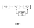
FIG. 1 is a block diagram that illustrates exemplary elements of a clamp-hubcap assembly, in accordance with various embodiments. -
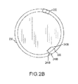
FIGs. 2A-2C illustrate profile views of clamp-hubcap assemblies, in accordance with various embodiments. -
FIGs. 3A-3B illustrate partial cross-sectional views of a portion of a clamp-hubcap assembly installed on a wheel, in accordance with various embodiments. -
FIGs. 4A-4B illustrate partial cross-sectional views of a portion of a clamp-hubcap assembly installed on a wheel, in accordance with various embodiments. - The detailed description of exemplary embodiments herein makes reference to the accompanying drawings, which show exemplary embodiments by way of illustration and their best mode. While these exemplary embodiments are described in sufficient detail to enable those skilled in the art to practice the inventions, it should be understood that other embodiments may be realized and that logical, chemical and mechanical changes may be made without departing from the scope of the disclosure. Thus, the detailed description herein is presented for purposes of illustration only and not of limitation. For example, the steps recited in any of the method or process descriptions may be executed in any order and are not necessarily limited to the order presented.
- Furthermore, any reference to singular includes plural embodiments, and any reference to more than one component or step may include a singular embodiment or step.
- Surface shading lines may be used throughout the figures to denote different parts but not necessarily to denote the same or different materials.
- Vehicles that comprise wheels often include hubcaps that protect internal rotating components in the wheel, such as for example, bearings, bushings, and/or the like. The hubcap may be retained by a clamp that ties, couples and/or otherwise clamps the hubcap to the wheel. The hubcap and clamp may be removed to perform maintenance operations and/or the like. During these maintenance operations the clamp and/or hubcap are removed and place aside (e.g., set on the ground so that a technician may access the wheel or other structures to conduct the maintenance operation).
- In various embodiments, the clamp may be any suitable structure, shape, and/or configuration suitable for retaining a hubcap on a wheel. For example, the clamp may be a v-clamp (e.g., a clamp having a substantially "v" shaped portion), a u-clamp (e.g., a clamp having a substantially "u" shaped portion), an o-clamp, a u-bolt (e.g., a bolt having a substantially "u" shaped portion), a band clamp, an asymmetric clamp, and/or the like.
- The retaining devices described herein provide cost effective, reliable, and efficient mechanisms for creating hubcap/clamp assemblies. In various embodiments, the clamp and hubcap may be coupled or fixed together to form an assembly. In this regard, the assembly is less likely to be lost or displaced (e.g., kicked) during a maintenance operation, which reduces the risk of FOD in an aircraft operating environment. The assembly may be provided as a single line-replaceable unit ("LRU"), as opposed to multiple LRUs (e.g., for the clamp and hubcap, separately).
- In various embodiments and with reference to
FIG. 1 , a vehicle such as an aircraft may comprise landing gear or a drive train with awheel 110 and ahubcap 120. Hubcap 120 may be installable onwheel 110. Hubcap 120 may be retained and/or secured towheel 110 with aclamp 130. Hubcap 120 andclamp 130 may be coupled to one another by aretaining device 140. - In various embodiments,
retaining device 140 may be any suitable structure that is capable of coupling, attaching, securing and/or otherwise joininghubcap 120 andclamp 130. For example,retaining device 140 may be a tab, a cable, a bond (e.g., a weld, a braze, an adhesive, and/or the like), a fastener (e.g., a screw, rivet, pin, and/or the like), and/or a bracket. - In various embodiments and with reference to
FIG. 2A ,clamp 230 may have a generally circular shape.Clamp 230 may have free ends (e.g., a firstfree end 231 and a second free end 233) that couple to one another when installed onwheel 110, as shown inFIG. 1 , and/orhubcap 220.Free ends coupling mechanism 232. For example, firstfree end 231 may comprise a bolt and secondfree end 233 may receive a nut (e.g.,coupling mechanism 232 comprises a bolt and a nut). In this regard the bolt may be coupled to the nut to secure firstfree end 231 to the secondfree end 233, and similarly, secure and/orcouple hubcap 220 to a wheel. - In various embodiments shown in
FIGS. 2A-2C , a retaining mechanism, such asretaining mechanisms 240A through 240C may affix and/or fixedly attachclamp 230 to hubcap 220. In this regard,retaining mechanisms 240A through 240C may be fixedly attached to bothclamp 230 andhubcap 220, but may allow movement betweenclamp 230 and hubcap 220 (e.g., where the retaining device is a wire or cable). Retainingmechanisms 240A through 240C may be installed at any suitable location ofclamp 230 and/orhubcap 220. In this regard,retaining mechanisms 240A through 240C may be installed along a portion of the generally circular diameter such thatfree ends clamp 230/hubcap 220 assembly is installed on the wheel. - In various embodiments and with continued reference to
FIG. 2A , the retaining device may be atab 240A.Tab 240A may comprise afirst end 241 A and asecond end 243A. Thefirst end 241A may be attached toclamp 230 and thesecond end 243A may be attached tohubcap 220. For example, thefirst end 241A may be attached with a fastener or bond. Similarly, thesecond end 243A may be attached with a fastener or bond. - In various embodiments and with reference to
FIG. 2B , the retaining device may comprisecable 240B (e.g., a wire, cord and/or the like).Cable 240B may comprise afirst end 241B and asecond end 243B. Thefirst end 241B may be attached to clamp 230 and thesecond end 243B may be attached tohubcap 220. For example, thefirst end 241B may be attached with a fastener or bond. Similarly, thesecond end 243B may be attached with a fastener or bond.Cable 240B may be any suitable materials such as for example, a metal (e.g., aluminum, steel, titanium, and/or any other suitable metal or alloy), a polymer (e.g., nylon), a composite, and/or any other suitable material. - In various embodiments and with reference to
FIG. 2C , the retaining device may be abond 240C.Bond 240C may be a weld, braze, adhesive and/or thelike bonding hubcap 220 to clamp 230. Moreover,bond 240C may couple and/or attachhubcap 220 to at least a portion ofclamp 230. - In various embodiments and with reference to
FIG. 3A , the retaining device may be afastener 340D.Fastener 340D may be screw, rivet, pin, and/or the like. For example,fastener 340D may be configured to pass through a portion (such as an opening) ofclamp 330 and engagehubcap 320. Similarly,fastener 340D may be configured to pass through a portion ofhubcap 320 and engageclamp 330. In this regard,fastener 340D may attach or rigidlycouple clamp 330 andhubcap 320 together such that they assembly is installable onwheel 310. - In various embodiments and with reference to
FIG. 3B , the retaining device may be abracket 340E.Bracket 340E may comprise afirst end 341E and asecond end 343E. Thefirst end 341E may be attached to clamp 330 and thesecond end 343E may be attached tohubcap 320. For example, thefirst end 341E may be attached with a fastener or bond. Similarly, thesecond end 343E may be attached with a fastener or bond. - In various embodiments and with reference to
FIGs. 4A-4B , clamp 430 may be any suitable shape or geometry. For example, clamp 430 may be asymmetric and/or may have a non-uniform or un-equal profile. In this regard, afirst portion 431 ofclamp 430 may be larger than asecond portion 433 ofclamp 430.First portion 431 may be coupled to or fixed tohubcap 420.Second portion 433 may be installable onwheel 410. Moreover,second portion 433 may be sized to be easily installed onwheel 410 and then tightened to securehubcap 420 towheel 410. Moreover, clamp 430 (e.g., first portion 431) may be coupled tohubcap 420 by retaining device 440 (e.g., a tab, a cable, a bond (e.g., a weld, a braze, an adhesive, and/or the like), a fastener (e.g., a screw, rivet, pin, and/or the like), and/or a bracket as described herein). - Benefits, other advantages, and solutions to problems have been described herein with regard to specific embodiments. Furthermore, the connecting lines shown in the various figures contained herein are intended to represent exemplary functional relationships and/or physical couplings between the various elements. It should be noted that many alternative or additional functional relationships or physical connections may be present in a practical system. However, the benefits, advantages, solutions to problems, and any elements that may cause any benefit, advantage, or solution to occur or become more pronounced are not to be construed as critical, required, or essential features or elements of the inventions. The scope of the inventions is accordingly to be limited by nothing other than the appended claims, in which reference to an element in the singular is not intended to mean "one and only one" unless explicitly so stated, but rather "one or more." Moreover, where a phrase similar to "at least one of A, B, or C" is used in the claims, it is intended that the phrase be interpreted to mean that A alone may be present in an embodiment, B alone may be present in an embodiment, C alone may be present in an embodiment, or that any combination of the elements A, B and C may be present in a single embodiment; for example, A and B, A and C, B and C, or A and B and C. Different cross-hatching is used throughout the figures to denote different parts but not necessarily to denote the same or different materials.
- Systems, methods and apparatus are provided herein. In the detailed description herein, references to "various embodiments", "one embodiment", "an embodiment", "an example embodiment", etc., indicate that the embodiment described may include a particular feature, structure, or characteristic, but every embodiment may not necessarily include the particular feature, structure, or characteristic. Moreover, such phrases are not necessarily referring to the same embodiment. Further, when a particular feature, structure, or characteristic is described in connection with an embodiment, it is submitted that it is within the knowledge of one skilled in the art to affect such feature, structure, or characteristic in connection with other embodiments whether or not explicitly described. After reading the description, it will be apparent to one skilled in the relevant art(s) how to implement the disclosure in alternative embodiments.
- Furthermore, no element, component, or method step in the present disclosure is intended to be dedicated to the public regardless of whether the element, component, or method step is explicitly recited in the claims. No claim element herein is to be construed under the provisions of 35 U.S.C. 112, sixth paragraph, unless the element is expressly recited using the phrase "means for." As used herein, the terms "comprises", "comprising", or any other variation thereof, are intended to cover a non-exclusive inclusion, such that a process, method, article, or apparatus that comprises a list of elements does not include only those elements but may include other elements not expressly listed or inherent to such process, method, article, or apparatus.
Claims (15)
- A wheel assembly, comprising:an aircraft wheel (110; 210; 310; 410);a hubcap (120; 220; 320; 420) installable on the aircraft wheel (110; 210; 310; 410);a clamp (130; 230; 330; 430) configured to engage the wheel (110; 210; 310 410) and the hubcap (120; 220; 320; 420); anda retaining device (140; 240A; 240B; 240C; 340D; 340E; 440) fixedly attached to the hubcap (120; 220; 320; 420) and the clamp (130; 230; 330; 430).
- The wheel assembly of claim 1, wherein the retaining device (140; 240A; 240B; 240C; 340D; 340E; 440) comprises a first end (24 1 A; 241B; 341 E) coupled to the clamp (130; 230; 330; 430) and a second end (243A; 243B; 243E) coupled to the hubcap (120; 220; 320; 420).
- The wheel assembly of claim 1 or 2, wherein the retaining device (140; 240A; 240B; 240C; 340D; 340E; 440) is at least one of a bracket (340E), a tab (240A), a cable (240B), a cord, and a wire.
- The wheel assembly of claim 1 or 2, wherein the retaining device (140; 240A; 240B; 240C; 340D; 340E; 440) is a bond (240C), or alternatively a fastener (340D).
- The wheel assembly of claim 4, wherein the bond (240C) is at least one of a weld, a braze, and an adhesive.
- The wheel assembly of claim 4, wherein the fastener (340D) is at least one of a screw, a pin, and a rivet.
- The wheel assembly of claim 4 or 6, wherein the fastener (340D) is configured to pass through the clamp (130; 230; 330; 430) and engage the hubcap (120; 220; 320; 420).
- A hubcap assembly, comprising:a hubcap (120; 220; 320; 420);a clamp (130; 230; 330; 430); anda retaining device (140; 240A; 240B; 240C; 340D; 340E; 440) comprising a first end (241A; 241B; 341E) and a second end (243A; 243B; 343E), the first end (241A; 241B; 341E) coupled to the clamp (130; 230; 330; 430) and the second end (243A; 243B; 343E) coupled to the hubcap (120; 220; 320; 420).
- The hubcap assembly of claim 8, wherein the hubcap assembly is installable on a wheel (110; 210; 310; 410).
- The hubcap assembly of claim 8 or 9, wherein the retaining device (140; 240A; 240B; 240C; 340D; 340E; 440) is a fastener (340D).
- The hubcap assembly of claim 10, wherein the fastener (340D) is at least one of a screw, a pin, and a rivet.
- The hubcap assembly of claim 8 or 9, wherein the retaining device (140; 240A; 240B; 240C; 340D; 340E; 440) is at least one of a bracket (340E) and a tab (240A).
- The hubcap assembly of claim 8 or 9, wherein the retaining device (140; 240A; 240B; 240C; 340D; 340E; 440) is a bond (240C).
- The hubcap assembly of claim 13, wherein the bond (240C) is at least one of a weld, a braze, and an adhesive.
- The hubcap assembly of claim 8 or 9, wherein the retaining device (140; 240A; 240B; 240C; 340D; 340E; 440) is at least one of a cable (240B), a wire, and a cord.
Applications Claiming Priority (1)
| Application Number | Priority Date | Filing Date | Title |
|---|---|---|---|
| US13/952,146 US9272570B2 (en) | 2013-07-26 | 2013-07-26 | Integral clamp hubcap for wheel system and apparatus |
Publications (1)
| Publication Number | Publication Date |
|---|---|
| EP2862801A1 true EP2862801A1 (en) | 2015-04-22 |
Family
ID=50842147
Family Applications (1)
| Application Number | Title | Priority Date | Filing Date |
|---|---|---|---|
| EP20140170781 Withdrawn EP2862801A1 (en) | 2013-07-26 | 2014-06-02 | Integral clamp hubcap for wheel system and apparatus |
Country Status (2)
| Country | Link |
|---|---|
| US (1) | US9272570B2 (en) |
| EP (1) | EP2862801A1 (en) |
Families Citing this family (2)
| Publication number | Priority date | Publication date | Assignee | Title |
|---|---|---|---|---|
| AU2020376913A1 (en) | 2019-10-31 | 2022-05-19 | Otr Wheel Engineering, Inc. | Wheel assembly, lock-ring for wheel assembly, handle engageable with lock-ring, and related methods |
| USD981316S1 (en) | 2019-10-31 | 2023-03-21 | Otr Wheel Engineering, Inc. | Wheel lock ring assembly |
Citations (8)
| Publication number | Priority date | Publication date | Assignee | Title |
|---|---|---|---|---|
| US2460784A (en) * | 1944-04-10 | 1949-02-01 | Lyon George Albert | Wheel cover |
| US2601209A (en) * | 1948-10-15 | 1952-06-17 | Lyon George Albert | Wheel cover |
| US2601017A (en) * | 1948-10-07 | 1952-06-17 | Products Mfg Co Inc | Hubcap retainer |
| US2695195A (en) * | 1952-01-10 | 1954-11-23 | James W O'day | Antitheft hubcap |
| FR61026E (en) * | 1950-04-24 | 1955-03-23 | Wheel fixing cover for automobiles | |
| US3883181A (en) * | 1972-04-05 | 1975-05-13 | Plastaspec Inc | Decorative wheel cover and retaining assembly therefor |
| US4116490A (en) * | 1977-06-29 | 1978-09-26 | Eddie Huff | Cable type lock for wire wheel hubcaps |
| FR2979581A1 (en) * | 2011-09-07 | 2013-03-08 | Peugeot Citroen Automobiles Sa | Wheel for car, has cover for partially covering outer face of shell of rim and comprising central portion and set of side portions that hide fastening screws and give access to fastening screws by elastic deformation |
Family Cites Families (5)
| Publication number | Priority date | Publication date | Assignee | Title |
|---|---|---|---|---|
| US1889070A (en) * | 1930-05-29 | 1932-11-29 | Auld D L Co | Hub cap fastener |
| US7438367B2 (en) * | 2003-02-13 | 2008-10-21 | Allsop M Sid | Hub cap having an air valve for bearing cavity pressurization |
| US20070290548A1 (en) * | 2006-06-14 | 2007-12-20 | Lundy Larry L | Wheel Rim Protector |
| US9039101B1 (en) * | 2012-02-29 | 2015-05-26 | Peter Danto | Aircraft hubcap structure |
| US9199508B2 (en) * | 2012-06-18 | 2015-12-01 | Brian S. Kronemeyer | Wheel cover |
-
2013
- 2013-07-26 US US13/952,146 patent/US9272570B2/en not_active Expired - Fee Related
-
2014
- 2014-06-02 EP EP20140170781 patent/EP2862801A1/en not_active Withdrawn
Patent Citations (8)
| Publication number | Priority date | Publication date | Assignee | Title |
|---|---|---|---|---|
| US2460784A (en) * | 1944-04-10 | 1949-02-01 | Lyon George Albert | Wheel cover |
| US2601017A (en) * | 1948-10-07 | 1952-06-17 | Products Mfg Co Inc | Hubcap retainer |
| US2601209A (en) * | 1948-10-15 | 1952-06-17 | Lyon George Albert | Wheel cover |
| FR61026E (en) * | 1950-04-24 | 1955-03-23 | Wheel fixing cover for automobiles | |
| US2695195A (en) * | 1952-01-10 | 1954-11-23 | James W O'day | Antitheft hubcap |
| US3883181A (en) * | 1972-04-05 | 1975-05-13 | Plastaspec Inc | Decorative wheel cover and retaining assembly therefor |
| US4116490A (en) * | 1977-06-29 | 1978-09-26 | Eddie Huff | Cable type lock for wire wheel hubcaps |
| FR2979581A1 (en) * | 2011-09-07 | 2013-03-08 | Peugeot Citroen Automobiles Sa | Wheel for car, has cover for partially covering outer face of shell of rim and comprising central portion and set of side portions that hide fastening screws and give access to fastening screws by elastic deformation |
Also Published As
| Publication number | Publication date |
|---|---|
| US20150028661A1 (en) | 2015-01-29 |
| US9272570B2 (en) | 2016-03-01 |
Similar Documents
| Publication | Publication Date | Title |
|---|---|---|
| US9254908B2 (en) | Fixing means | |
| EP3421362B1 (en) | Frangible fasteners with flexible connectors for unmanned aircraft, and associated systems and methods | |
| EP3480072A1 (en) | Shield attachment device | |
| EP3327308A1 (en) | Bridged clip retainer for brake system | |
| US9789948B2 (en) | Tool for simultaneously holding several attachment clips in contact with an aircraft fuselage frame element | |
| US9561700B2 (en) | Connecting arrangement between a wheel-guiding link of a vehicle wheel suspension and a flange | |
| US10077818B2 (en) | Scalloped aircraft wheel rotor drive bar attachment boss for reduced thermal conduction | |
| US20170297185A1 (en) | Non-destructive cold extractions of press fit bushings | |
| US9272570B2 (en) | Integral clamp hubcap for wheel system and apparatus | |
| EP2492455A3 (en) | A gas turbine joint assembly | |
| CN108291524A (en) | Wind energy facility rotor blade and wind energy facility | |
| EP3020999A1 (en) | Aircraft brake puck assembly | |
| US9931688B2 (en) | Blind tack bolt with higher clamp-up strength | |
| US9963234B2 (en) | Energy absorbing assembly for aircraft seat | |
| EP3053758A2 (en) | Wheel assembly tie bolt retention system | |
| US20170157696A1 (en) | Fastening System and Method for Producing a Fastening System | |
| EP3324059B1 (en) | Nut retention system | |
| US20090072115A1 (en) | Wind-resistant sign assembly | |
| US20210245564A1 (en) | Axle mounting unit | |
| CN204548077U (en) | A kind of brake cable pull and brake system of car | |
| US9890662B2 (en) | Ram air turbine stow lock pin | |
| US10830376B2 (en) | Composite structure having an integrated support | |
| JP2003113828A (en) | Bolt scattering prevention device | |
| CN203996269U (en) | Alleviate the manual handle component of braking | |
| WO2010062970A1 (en) | Service adapter kit |
Legal Events
| Date | Code | Title | Description |
|---|---|---|---|
| PUAI | Public reference made under article 153(3) epc to a published international application that has entered the european phase |
Free format text: ORIGINAL CODE: 0009012 |
|
| 17P | Request for examination filed |
Effective date: 20140602 |
|
| AK | Designated contracting states |
Kind code of ref document: A1 Designated state(s): AL AT BE BG CH CY CZ DE DK EE ES FI FR GB GR HR HU IE IS IT LI LT LU LV MC MK MT NL NO PL PT RO RS SE SI SK SM TR |
|
| AX | Request for extension of the european patent |
Extension state: BA ME |
|
| R17P | Request for examination filed (corrected) |
Effective date: 20151022 |
|
| RBV | Designated contracting states (corrected) |
Designated state(s): AL AT BE BG CH CY CZ DE DK EE ES FI FR GB GR HR HU IE IS IT LI LT LU LV MC MK MT NL NO PL PT RO RS SE SI SK SM TR |
|
| STAA | Information on the status of an ep patent application or granted ep patent |
Free format text: STATUS: THE APPLICATION IS DEEMED TO BE WITHDRAWN |
|
| 18D | Application deemed to be withdrawn |
Effective date: 20180103 |