EP2862751A1 - Tractor - Google Patents
Tractor Download PDFInfo
- Publication number
- EP2862751A1 EP2862751A1 EP20140188312 EP14188312A EP2862751A1 EP 2862751 A1 EP2862751 A1 EP 2862751A1 EP 20140188312 EP20140188312 EP 20140188312 EP 14188312 A EP14188312 A EP 14188312A EP 2862751 A1 EP2862751 A1 EP 2862751A1
- Authority
- EP
- European Patent Office
- Prior art keywords
- frame
- roof
- attachment
- tractor
- safety
- Prior art date
- Legal status (The legal status is an assumption and is not a legal conclusion. Google has not performed a legal analysis and makes no representation as to the accuracy of the status listed.)
- Granted
Links
- 230000008878 coupling Effects 0.000 description 13
- 238000010168 coupling process Methods 0.000 description 13
- 238000005859 coupling reaction Methods 0.000 description 13
- 230000005540 biological transmission Effects 0.000 description 6
- 230000002787 reinforcement Effects 0.000 description 5
- 238000005452 bending Methods 0.000 description 4
- 230000001133 acceleration Effects 0.000 description 3
- 241000219122 Cucurbita Species 0.000 description 2
- 235000009852 Cucurbita pepo Nutrition 0.000 description 2
- 239000005357 flat glass Substances 0.000 description 2
- 238000010276 construction Methods 0.000 description 1
- 239000000446 fuel Substances 0.000 description 1
- 239000002420 orchard Substances 0.000 description 1
- 239000002689 soil Substances 0.000 description 1
Images




Classifications
-
- B—PERFORMING OPERATIONS; TRANSPORTING
- B62—LAND VEHICLES FOR TRAVELLING OTHERWISE THAN ON RAILS
- B62D—MOTOR VEHICLES; TRAILERS
- B62D33/00—Superstructures for load-carrying vehicles
- B62D33/06—Drivers' cabs
- B62D33/0617—Drivers' cabs for tractors or off-the-road vehicles
-
- B—PERFORMING OPERATIONS; TRANSPORTING
- B60—VEHICLES IN GENERAL
- B60R—VEHICLES, VEHICLE FITTINGS, OR VEHICLE PARTS, NOT OTHERWISE PROVIDED FOR
- B60R21/00—Arrangements or fittings on vehicles for protecting or preventing injuries to occupants or pedestrians in case of accidents or other traffic risks
- B60R21/02—Occupant safety arrangements or fittings, e.g. crash pads
- B60R21/13—Roll-over protection
- B60R21/131—Protective devices for drivers in case of overturning of tractors
-
- B—PERFORMING OPERATIONS; TRANSPORTING
- B62—LAND VEHICLES FOR TRAVELLING OTHERWISE THAN ON RAILS
- B62D—MOTOR VEHICLES; TRAILERS
- B62D33/00—Superstructures for load-carrying vehicles
- B62D33/06—Drivers' cabs
Definitions
- the present invention relates to a tractor equipped with a two-strut type safety frame that has two struts.
- a well-known conventional tractor is equipped with a reverse U-shaped two-strut safety frame that has two struts erected from right and left side portions rearward from an operator's seat.
- Right and left frames may be optionally mounted on the tractor so as to extend from a portion forward from the seat to an upper portion of the safety frame.
- the right and left frames mounted on the tractor are rotatable laterally distally.
- the right and left frames are advantageous to protect an operator sitting on the seat from branches of trees during traveling of the tractor in an orchard. Even if the tractor turns over and lies on its side, an operator can rotate the right or left frame laterally distally so as to ensure a way for escape of the operator from the tractor.
- the right and left frames are not adaptable so as to be provided thereon with any additional members, e.g., a roof or a door, for constituting a cabin or a canopy for weatherproofing or sun-shading an operator sitting on the seat.
- An object of the invention is to provide a tractor equipped with a two-strut safety frame, which is improved so as to be able to be used for optionally mounting a cabin or canopy having four struts on the tractor.
- a tractor comprises a seat, a safety frame, a vehicle body frame, right and left attachment brackets, a front frame and a roof frame.
- the safety frame has two struts standing from right and left side portions rearward from the seat.
- the right and left attachment brackets are fixed on both right and left outer surfaces of the vehicle body frame.
- the front frame is formed in a gate shape in front view so as to have right and left lower portions detachably attached to the right and left attachment brackets.
- the roof frame is detachably attached so as to connect a right or left upper portion of the front frame to a right or left upper portion of the safety frame.
- the front frame and the roof frame can be optionally attached to the two-strut type safety frame so that the two-strut type safety frame and the front frame and the roof frame attached to the safety frame serve as a safety frame having four struts (hereinafter referred to as four-strut type safety frame), which is adaptable as a fundamental framework of a canopy or a cabin.
- four-strut type safety frame which is adaptable as a fundamental framework of a canopy or a cabin.
- the tractor further comprises a roof attachment member and a roof.
- the roof attachment member is provided on an outer side of the roof frame.
- the roof is attached to the roof attachment member.
- the four-strut type safety frame having the roof mounted on the roof frame via the roof attachment member serves as a canopy for sun-shading and rain-proofing an operator sitting on the seat, and can serve as a cabin for sun-shading and weatherproofing the operator if only it is further provided with additional members for constituting a cabin, e.g., a door and a window glass.
- the tractor further comprises a hinge attachment portion and a door.
- the hinge attachment portion is provided on an outer surface of the right or left upper portion of the safety frame.
- the door is attached to the hinge attachment portion via a hinge so as to cover a side surface defined by the safety frame, the front frame and the roof frame.
- the four-strut type safety frame having the door attached to the hinge attachment portion can serve as a cabin if only it is further provided with other members for constituting a cabin, e.g., a roof and a window glass.
- a tractor of the present invention is applicable to a working vehicle such as agricultural machinery and construction machinery including a safety frame that protects an operation portion.
- FIG. 1 shows the overall structure of the tractor 100.
- F indicates the front direction of the tractor 100.
- the tractor 100 mainly includes a vehicle body frame 1, an engine 2, a mission casing 3, a front axle casing 4, and a rear axle casing 5.
- the tractor 100 includes a front loader 6 on the front portion.
- the vehicle body frame 1 serves as the main structure for the tractor 100.
- the frame structure is not limited, and an engine frame, a clutch housing, and a mission casing may integrally form the vehicle body frame.
- the vehicle body frame 1 has a shape of a rectangular frame with a pair of left and right longitudinal frames 1a and 1a and lateral frames 1b, 1b, and 1b laid between the left and the right longitudinal frames 1a and 1a.
- the engine 2 is placed and fixed on a front upper portion of the vehicle body frame 1.
- the front axle casing 4 is attached to a front lower portion of the vehicle body frame 1.
- the mission casing 3 is attached to a rear portion of the vehicle body frame 1.
- An operation portion 8 is disposed on the center portion of the vehicle body frame 1 in the front and rear direction.
- the engine 2 converts energy obtained by burning a fuel into rotational movement.
- an acceleration pedal or an acceleration lever disposed in the operation portion 8
- the engine 2 changes the driving state in accordance with the operation.
- the engine 2 maintains the rotational speed at a constant level even when the load changes.
- the mission casing 3 accommodates a transmission for switching between forward and backward movement of the tractor 100 and shifting the speed of the tractor 100.
- the transmission includes a hydromechanical continuously variable transmission (HMT or I-HMT) as a transmission device.
- HMT hydromechanical continuously variable transmission
- a base portion of a safety frame 20 described later is attached to a rear portion of the mission casing 3.
- the safety frame 20 can be attached to the rear axle casing 5.
- a PTO output mechanism is provided to the rear portion of the mission casing 3. The rotational energy can be transmitted to an implement through the PTO output mechanism.
- the front axle casing 4 accommodates an input shaft, a front differential device, and the like that transmit the rotational energy from the engine 2 to front wheels 11.
- the rotational energy from the engine 2 is input to the front axle casing 4 through the transmission.
- the front axle casing 4 is disposed next to a steering device. When the operator operates a handle 15, the steering device changes a steering angle of the front wheels 11 in accordance with the operation.
- the rear axle casing 5 includes a reducing gear, a rear axle, and the like, and transmits the rotational energy from the engine 2 to rear wheels 12.
- the operation portion 8 includes the handle 15, the seat 16, an acceleration lever, a gear lever, an operation lever, a loader lever 17, and the like.
- the front loader 6 includes loader struts 31, a loader arm 32, an arm cylinder 33, a bucket 34, and a bucket cylinder 35.
- the bucket 34 disposed on the front side of the tractor 100 can be rotated upward and downward by the arm cylinder 33 and the bucket cylinder 35.
- the bucket 34 can scoop, move, and place soil and the like.
- the pair of left and right loader struts 31 stand from attachment brackets 30 fixed on side surfaces at an intermediate portion, of the vehicle body frame 1, in the front and rear direction.
- the attachment brackets 30 are disposed on front left and right outer sides of the step of the operation portion 8.
- the loader struts 31 are disposed on the sides of the rear portion of a hood covering the engine 2.
- the loader struts 31 are attached to upper portions of the attachment brackets 30 in a removable manner.
- a base portion of the loader arm 32 is supported on the upper portions of the loader struts 31 in a rotatable manner.
- a base portion of the arm cylinder 33 is supported on an intermediate portion of the loader strut 31 in the upper and lower direction, in a rotatable manner.
- the loader arm 32 has a dogleg shape in side view.
- the base portion of the loader arm 32 is pivotally supported on the upper portion of the loader strut 31.
- the arm cylinder 33 is interposed between an intermediate portion of the loader arm 32 and the loader strut 31.
- the loader arm 32 can be moved upward and downward by extending and contracting the arm cylinder 33.
- a rear lower portion of the bucket 34 is pivotally supported on a distal end of the loader arm 32.
- the bucket cylinder 35 is interposed between the rear upper portion of the bucket 34 and an intermediate portion of the loader arm 32 in the front and rear direction.
- the bucket 34 can be rotated by extending and contracting the bucket cylinder 35.
- Attachment brackets 30 each include an attachment plate 30a, a supporting pipe 30b, and a base plate 30c, as shown in FIG. 5 .
- the attachment bracket 30 protrudes outward from an intermediate portion of the side plate of the vehicle body frame 1, in the front and rear direction. Screw holes are formed in the base plate 30c. The screw holes are used to fix the base plates 30c to the vehicle body frame 1 with bolts.
- the supporting pipes 30b with the axial center in the left and right direction are welded and fixed on to the side surfaces of the base plates 30c.
- a lower inner side surface of the attachment plate 30a is welded and fixed on the outer side of the supporting pipe 30b.
- the lower outer side surface of the attachment plate 30a is provided with screw holes for fixing a strut bracket 25 disposed on the lower end of a front strut 24 described later by bolts.
- the attachment plate 30a includes an engagement recess and a bolt fixing portion, at an upper portion. A lower portion of the loader strut 31 is engaged with the engagement recess and the bolt fixing portion, so that the loader strut 31 is easily attached and detached.
- a gate shaped front frame 21 and roof frames 23 and 23 are able to be attached and detached between the attachment bracket 30 and the safety frame 20.
- the front frame 21 includes the front struts 24 and 24 standing from the left and the right attachment brackets 30 and an upper frame 26 coupling between the front struts 24 and 24.
- the safety frame 20 is formed by bending a square pipe into a reversed U shape in rear view.
- a reinforcement frame 29 is laterally disposed to horizontally extend in the left and right direction at a lower portion of the safety frame 20.
- Lower ends of the safety frame 20 are attached and fixed on to side surfaces of the mission casing 3 via attachment plates 22 and 22.
- the attachment plate 22 is formed to have an approximately triangular shape in side view.
- a rear portion of the attachment plate 22 is fixed on the lower inner surface of the safety frame 20.
- a lower portion of the attachment plate 22 is fixed by bolts on the corresponding one of the left and the right side surfaces of the mission casing 3.
- FIG. 8 Left and right front surfaces of an upper portion of the safety frame 20 are provided with screw holes.
- a rear portion of the roof frame 23 is able to be fixed to the front surfaces with bolts.
- a hinge attachment portion 20b is disposed on an upper side surface of the safety frame 20.
- screw holes 20a are formed in the hinge attachment portion 20b, and thus, a hinge 42 ( FIG. 3 ) is attached to the hinge attachment portion 20b, and a door 41 is attached to the hinge 42.
- Upper portions of the front struts 24 are respectively fixed to front portions of roof frames 23 and left and right ends of the upper frame 26. Lower ends of the front struts 24 are respectively fixed to the attachment brackets 30 via the strut brackets 25.
- the front strut 24 is formed of a pipe having an approximately gourd shape in cross-sectional view.
- the upper portion of the front strut 24 is fixed by bolts, with the front coupling stay 23d disposed on the front portion of the roof frame 23 to be described later in contact with the upper inner diagonal surface of the front strut 24.
- One end of the upper frame 26 is welded to be fixed on the inner surface of the front strut 24.
- the upper frame 26 is formed by bending a plate body into an arc shape bulging toward the front.
- the left and the right ends of the upper frame 26 are brought into contact along recess portions of side surfaces of the front struts 24, to be welded to be fixed thereon.
- the upper frame 26 and the left and the right front struts 24 and 24 form the gate shape in front view.
- the strut bracket 25 includes a fixing plate 25a, side plates 25b and 25c, and an upper plate 25d.
- the side plates 25b and 25c protrude sideways on the front and the rear sides of the fixing plate 25a. Upper surfaces of the side plates 25b and 25c are covered by the upper plate 25d.
- a lower portion of the front strut 24 is welded and fixed on the outer ends of the side plates 25b and 25c and the upper plates 25d.
- the fixing plate 25a is provided with screw holes 25e, 25e, ..., through which bolts are screwed in and fastened so that the fixing plate 25a is fixed.
- a lower side of the strut bracket 25 is opened. Thus, the bolt is able to be easily screwed into one of the screw holes 25e on the lower side of the fixing plate 25 and fastened.
- the roof frame 23 couples and fixes the upper portion of the safety frame 20 with the upper portion of the front strut 24, and makes a roof 40 attachable.
- the roof frame 23 includes a main plate 23a, a reinforcement frame 23b, a rear coupling stay 23c, a front coupling stay 23d, and a roof attachment body 23e.
- the main plate 23a extends in the front and rear direction and is formed of a plate having an approximately dogleg shape in side view.
- the reinforcement frame 23b is formed by bending a square pipe to have the shape corresponding to that of the main plate 23a, and is fixed on the inner surface of the main plate 23a.
- the rear coupling stay 23c is fixed on the rear inner surfaces of the main plate 23a and the reinforcement frame 23b.
- the front coupling stay 23d is fixed on the front inner surfaces of the main plate 23a and the reinforcement frame 23b.
- the roof attachment body 23e is disposed on a center portion of the outer surface of the main plate 23a in the front and rear direction.
- the rear coupling stay 23c and the front coupling stay 23d are fixed on a plate surface of the main plate 23a while being perpendicular with respect to the main plate 23a.
- the rear coupling stay 23c and the front coupling stay 23d are provided with screw holes to be fixed by bolts.
- the rear coupling stay 23c is fixed on the corresponding one of the left and right side surfaces of the upper portion of the safety frame 20 by bolts ( FIG. 8 ).
- the front coupling stay 23d is fixed on the corresponding one of the left and right side surfaces of the inner diagonal surface of the upper portion of the front strut 24 by bolts ( FIG. 10 ).
- the left and right front struts 24 and 24 forming the gate shape together with the upper frame 26 are respectively fixed on the strut brackets 25 and 25.
- the roof frames 23 and 23 are laid across and coupled between the upper portions of the left and right front struts 24 and 24 and the both sides of the upper portion of the safety frame 20.
- the roof 40 is fixed on the roof attachment body 23e disposed on each of the roof frames 23 and 23.
- the vehicle type is able to be changed from that of the tractor including the roof 40 shown in FIG. 2 to the cabin type shown in FIG. 3 .
- the safety frame 20 is formed by bending a square pipe having an approximately rectangular cross sectional shape, and thus has a flat rear surface.
- a periphery of a rear window 44 (excluding a lower portion) is able to come into surface contact with the safety frame 20. Therefore, a closed space with no gap is able to be formed.
- the rear window 44 has an upper portion supported by a hinge to have a lower end rotatable toward the front and back. Thus, the rear window 44 is able to be opened backward.
- the side surface of the safety frame 20 is also a flat surface.
- the side surface of the safety frame 20 is provided with the hinge attachment portion 20b.
- the hinge attachment portion 20b is provided with screw holes, to which the hinges 42 are attached.
- the rear portion of the door 41 is fixed on the hinges 42.
- the front strut 24 has an approximately gourd shape in cross sectional view. Grooves are formed on the rear and inner surfaces of the front strut 24.
- the front window 43 has a convex surface bulging toward the front.
- the tractor 100 includes the two-strut type safety frame 20 standing from right and left side portions rearward from the seat 16.
- the attachment brackets 30 are fixed on both left and right outer surfaces of the vehicle body frame 1.
- the lower portions of the front frame 21 having a gate shape in front view are able to be respectively attached to and detached from the left and the right attachment brackets 30.
- the roof frames 23 and 23 coupling between the left and right upper portions of front frame 21 and the left and right upper portions of the safety frame 20 are attachable and detachable.
- the two-strut type safety frame 20 is able to be easily turned into the four-strut type safety frame by attaching the front frame 21 and the roof frames 23.
- the tractor 100 is able to be easily turned into the cabin type.
- the two-strut type safety frame is able to be used as it is, and thus, the number of parts is able to be reduced, and cost increase for changing to the cabin type is able to be held down.
- the roof attachment bodies 23e are disposed on outer sides of the roof frames 23.
- the roof 40 is attached to the roof attachment bodies 23e.
- the roof is able to be easily attached and detached.
- the sunlight and rain are able to be easily blocked by the roof.
- the hinge attachment portions 20b are disposed on the left and right outer surfaces of the upper portion of the safety frame 20.
- the door 41 is attached to the hinge attachment portions 20b via the hinges 42.
- the door 41 covers the side surface defined by the safety frame 20, the front frame 21, and the roof frame 23.
- the door 41 is able to be easily attached, and the side surface of the four-strut type safety frame is able to be easily covered.
Landscapes
- Engineering & Computer Science (AREA)
- Mechanical Engineering (AREA)
- Chemical & Material Sciences (AREA)
- Combustion & Propulsion (AREA)
- Transportation (AREA)
- Body Structure For Vehicles (AREA)
Abstract
Description
- The present invention relates to a tractor equipped with a two-strut type safety frame that has two struts.
- As disclosed by
JP H11-115661 A - The right and left frames are advantageous to protect an operator sitting on the seat from branches of trees during traveling of the tractor in an orchard. Even if the tractor turns over and lies on its side, an operator can rotate the right or left frame laterally distally so as to ensure a way for escape of the operator from the tractor. However, the right and left frames are not adaptable so as to be provided thereon with any additional members, e.g., a roof or a door, for constituting a cabin or a canopy for weatherproofing or sun-shading an operator sitting on the seat.
- An object of the invention is to provide a tractor equipped with a two-strut safety frame, which is improved so as to be able to be used for optionally mounting a cabin or canopy having four struts on the tractor.
- To achieve the object, a tractor comprises a seat, a safety frame, a vehicle body frame, right and left attachment brackets, a front frame and a roof frame. The safety frame has two struts standing from right and left side portions rearward from the seat. The right and left attachment brackets are fixed on both right and left outer surfaces of the vehicle body frame. The front frame is formed in a gate shape in front view so as to have right and left lower portions detachably attached to the right and left attachment brackets. The roof frame is detachably attached so as to connect a right or left upper portion of the front frame to a right or left upper portion of the safety frame.
- Therefore, the front frame and the roof frame can be optionally attached to the two-strut type safety frame so that the two-strut type safety frame and the front frame and the roof frame attached to the safety frame serve as a safety frame having four struts (hereinafter referred to as four-strut type safety frame), which is adaptable as a fundamental framework of a canopy or a cabin.
- Preferably, the tractor further comprises a roof attachment member and a roof. The roof attachment member is provided on an outer side of the roof frame. The roof is attached to the roof attachment member.
- Therefore, the four-strut type safety frame having the roof mounted on the roof frame via the roof attachment member serves as a canopy for sun-shading and rain-proofing an operator sitting on the seat, and can serve as a cabin for sun-shading and weatherproofing the operator if only it is further provided with additional members for constituting a cabin, e.g., a door and a window glass.
- Preferably, the tractor further comprises a hinge attachment portion and a door. The hinge attachment portion is provided on an outer surface of the right or left upper portion of the safety frame. The door is attached to the hinge attachment portion via a hinge so as to cover a side surface defined by the safety frame, the front frame and the roof frame.
- Therefore, the four-strut type safety frame having the door attached to the hinge attachment portion can serve as a cabin if only it is further provided with other members for constituting a cabin, e.g., a roof and a window glass.
- These, further and other objects, features and advantages of the invention will appear more fully from the following detailed description of the invention with reference to the attached drawings.
-
-
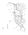
FIG. 1 is a side view of a tractor including a two-strut type safety frame. -
FIG. 2 is a side view of a tractor in which a roof is attached to a four-strut type safety frame. -
FIG. 3 is a side view of a tractor turned into to a cabin type by attaching a door. -
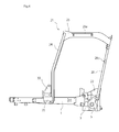
FIG. 4 is a side view of a structure where the safety frame and a front strut are attached to a vehicle body frame. -
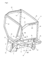
FIG. 5 is a rear perspective view of the same. -
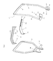
FIG. 6 is an exploded perspective view of the safety frame, the front strut, and a roof frame. -
FIG. 7 is a perspective view showing a lower attachment portion of the safety frame. -
FIG. 8 is a perspective view showing an attachment portion between an upper portion of the safety frame and a rear portion of the roof frame. -
FIG. 9 is a perspective view showing an attachment portion of the front strut. -
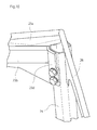
FIG. 10 is a perspective view showing an attachment portion among the upper portion of the front strut, a front portion of the roof frame, and an upper frame. - A tractor of the present invention is applicable to a working vehicle such as agricultural machinery and construction machinery including a safety frame that protects an operation portion.
- First, an overall structure of a
tractor 100 is described.FIG. 1 shows the overall structure of thetractor 100. In the figure, F indicates the front direction of thetractor 100. - The
tractor 100 mainly includes avehicle body frame 1, anengine 2, amission casing 3, afront axle casing 4, and arear axle casing 5. Thetractor 100 includes afront loader 6 on the front portion. - The
vehicle body frame 1 serves as the main structure for thetractor 100. The frame structure is not limited, and an engine frame, a clutch housing, and a mission casing may integrally form the vehicle body frame. As shown inFIG. 5 , thevehicle body frame 1 has a shape of a rectangular frame with a pair of left and rightlongitudinal frames lateral frames longitudinal frames - The
engine 2 is placed and fixed on a front upper portion of thevehicle body frame 1. Thefront axle casing 4 is attached to a front lower portion of thevehicle body frame 1. Themission casing 3 is attached to a rear portion of thevehicle body frame 1. Anoperation portion 8 is disposed on the center portion of thevehicle body frame 1 in the front and rear direction. - The
engine 2 converts energy obtained by burning a fuel into rotational movement. When an operator operates an acceleration pedal (or an acceleration lever) disposed in theoperation portion 8, theengine 2 changes the driving state in accordance with the operation. Theengine 2 maintains the rotational speed at a constant level even when the load changes. - The
mission casing 3 accommodates a transmission for switching between forward and backward movement of thetractor 100 and shifting the speed of thetractor 100. When the operator operates a shift lever, the operation state of the transmission changes in accordance with the operation. The transmission includes a hydromechanical continuously variable transmission (HMT or I-HMT) as a transmission device. A base portion of asafety frame 20 described later is attached to a rear portion of themission casing 3. Alternatively, thesafety frame 20 can be attached to therear axle casing 5. A PTO output mechanism is provided to the rear portion of themission casing 3. The rotational energy can be transmitted to an implement through the PTO output mechanism. - The
front axle casing 4 accommodates an input shaft, a front differential device, and the like that transmit the rotational energy from theengine 2 tofront wheels 11. The rotational energy from theengine 2 is input to thefront axle casing 4 through the transmission. Thefront axle casing 4 is disposed next to a steering device. When the operator operates ahandle 15, the steering device changes a steering angle of thefront wheels 11 in accordance with the operation. Therear axle casing 5 includes a reducing gear, a rear axle, and the like, and transmits the rotational energy from theengine 2 torear wheels 12. - The
operation portion 8 includes thehandle 15, theseat 16, an acceleration lever, a gear lever, an operation lever, aloader lever 17, and the like. - The
front loader 6 includes loader struts 31, aloader arm 32, anarm cylinder 33, abucket 34, and abucket cylinder 35. Thebucket 34 disposed on the front side of thetractor 100 can be rotated upward and downward by thearm cylinder 33 and thebucket cylinder 35. Thus, thebucket 34 can scoop, move, and place soil and the like. - The pair of left and right loader struts 31 stand from
attachment brackets 30 fixed on side surfaces at an intermediate portion, of thevehicle body frame 1, in the front and rear direction. Theattachment brackets 30 are disposed on front left and right outer sides of the step of theoperation portion 8. The loader struts 31 are disposed on the sides of the rear portion of a hood covering theengine 2. The loader struts 31 are attached to upper portions of theattachment brackets 30 in a removable manner. A base portion of theloader arm 32 is supported on the upper portions of the loader struts 31 in a rotatable manner. A base portion of thearm cylinder 33 is supported on an intermediate portion of theloader strut 31 in the upper and lower direction, in a rotatable manner. - The
loader arm 32 has a dogleg shape in side view. The base portion of theloader arm 32 is pivotally supported on the upper portion of theloader strut 31. Thearm cylinder 33 is interposed between an intermediate portion of theloader arm 32 and theloader strut 31. Theloader arm 32 can be moved upward and downward by extending and contracting thearm cylinder 33. - A rear lower portion of the
bucket 34 is pivotally supported on a distal end of theloader arm 32. Thebucket cylinder 35 is interposed between the rear upper portion of thebucket 34 and an intermediate portion of theloader arm 32 in the front and rear direction. Thebucket 34 can be rotated by extending and contracting thebucket cylinder 35. -
Attachment brackets 30 each include anattachment plate 30a, a supportingpipe 30b, and abase plate 30c, as shown inFIG. 5 . Theattachment bracket 30 protrudes outward from an intermediate portion of the side plate of thevehicle body frame 1, in the front and rear direction. Screw holes are formed in thebase plate 30c. The screw holes are used to fix thebase plates 30c to thevehicle body frame 1 with bolts. The supportingpipes 30b with the axial center in the left and right direction are welded and fixed on to the side surfaces of thebase plates 30c. A lower inner side surface of theattachment plate 30a is welded and fixed on the outer side of the supportingpipe 30b. The lower outer side surface of theattachment plate 30a is provided with screw holes for fixing astrut bracket 25 disposed on the lower end of afront strut 24 described later by bolts. Theattachment plate 30a includes an engagement recess and a bolt fixing portion, at an upper portion. A lower portion of theloader strut 31 is engaged with the engagement recess and the bolt fixing portion, so that theloader strut 31 is easily attached and detached. - A gate shaped
front frame 21 and roof frames 23 and 23 are able to be attached and detached between theattachment bracket 30 and thesafety frame 20. Thefront frame 21 includes the front struts 24 and 24 standing from the left and theright attachment brackets 30 and anupper frame 26 coupling between the front struts 24 and 24. - The
safety frame 20 is formed by bending a square pipe into a reversed U shape in rear view. Areinforcement frame 29 is laterally disposed to horizontally extend in the left and right direction at a lower portion of thesafety frame 20. Lower ends of thesafety frame 20 are attached and fixed on to side surfaces of themission casing 3 viaattachment plates FIG. 7 , theattachment plate 22 is formed to have an approximately triangular shape in side view. A rear portion of theattachment plate 22 is fixed on the lower inner surface of thesafety frame 20. As shown inFIG. 4 , a lower portion of theattachment plate 22 is fixed by bolts on the corresponding one of the left and the right side surfaces of themission casing 3. - Left and right front surfaces of an upper portion of the
safety frame 20 are provided with screw holes. Thus, as shown inFIG. 8 , a rear portion of theroof frame 23 is able to be fixed to the front surfaces with bolts. As shown inFIG. 4 , ahinge attachment portion 20b is disposed on an upper side surface of thesafety frame 20. In this embodiment, screw holes 20a are formed in thehinge attachment portion 20b, and thus, a hinge 42 (FIG. 3 ) is attached to thehinge attachment portion 20b, and adoor 41 is attached to thehinge 42. - Upper portions of the front struts 24 are respectively fixed to front portions of roof frames 23 and left and right ends of the
upper frame 26. Lower ends of the front struts 24 are respectively fixed to theattachment brackets 30 via thestrut brackets 25. As shown inFIGs. 9 and10 , thefront strut 24 is formed of a pipe having an approximately gourd shape in cross-sectional view. The upper portion of thefront strut 24 is fixed by bolts, with thefront coupling stay 23d disposed on the front portion of theroof frame 23 to be described later in contact with the upper inner diagonal surface of thefront strut 24. One end of theupper frame 26 is welded to be fixed on the inner surface of thefront strut 24. Theupper frame 26 is formed by bending a plate body into an arc shape bulging toward the front. The left and the right ends of theupper frame 26 are brought into contact along recess portions of side surfaces of the front struts 24, to be welded to be fixed thereon. Thus, theupper frame 26 and the left and the right front struts 24 and 24 form the gate shape in front view. - As shown in
FIGs. 6 and9 , thestrut bracket 25 includes a fixingplate 25a,side plates upper plate 25d. Theside plates plate 25a. Upper surfaces of theside plates upper plate 25d. A lower portion of thefront strut 24 is welded and fixed on the outer ends of theside plates upper plates 25d. The fixingplate 25a is provided withscrew holes plate 25a is fixed. A lower side of thestrut bracket 25 is opened. Thus, the bolt is able to be easily screwed into one of the screw holes 25e on the lower side of the fixingplate 25 and fastened. - The
roof frame 23 couples and fixes the upper portion of thesafety frame 20 with the upper portion of thefront strut 24, and makes aroof 40 attachable. As shown inFIG. 6 , theroof frame 23 includes amain plate 23a, areinforcement frame 23b, arear coupling stay 23c, afront coupling stay 23d, and aroof attachment body 23e. Themain plate 23a extends in the front and rear direction and is formed of a plate having an approximately dogleg shape in side view. Thereinforcement frame 23b is formed by bending a square pipe to have the shape corresponding to that of themain plate 23a, and is fixed on the inner surface of themain plate 23a. Therear coupling stay 23c is fixed on the rear inner surfaces of themain plate 23a and thereinforcement frame 23b. Thefront coupling stay 23d is fixed on the front inner surfaces of themain plate 23a and thereinforcement frame 23b. Theroof attachment body 23e is disposed on a center portion of the outer surface of themain plate 23a in the front and rear direction. - The
rear coupling stay 23c and thefront coupling stay 23d are fixed on a plate surface of themain plate 23a while being perpendicular with respect to themain plate 23a. Therear coupling stay 23c and thefront coupling stay 23d are provided with screw holes to be fixed by bolts. Thus, therear coupling stay 23c is fixed on the corresponding one of the left and right side surfaces of the upper portion of thesafety frame 20 by bolts (FIG. 8 ). Thefront coupling stay 23d is fixed on the corresponding one of the left and right side surfaces of the inner diagonal surface of the upper portion of thefront strut 24 by bolts (FIG. 10 ). - As described above, when the vehicle type is changed from that of the
tractor 100 including thesafety frame 20 shown inFIG. 1 to that of the tractor including theroof 40 shown inFIG. 2 , the left and right front struts 24 and 24 forming the gate shape together with theupper frame 26 are respectively fixed on thestrut brackets safety frame 20. Theroof 40 is fixed on theroof attachment body 23e disposed on each of the roof frames 23 and 23. Thus, the configuration where theroof 40 is attached on the four-strut type safety frame is able to be achieved. - The vehicle type is able to be changed from that of the tractor including the
roof 40 shown inFIG. 2 to the cabin type shown inFIG. 3 . Thesafety frame 20 is formed by bending a square pipe having an approximately rectangular cross sectional shape, and thus has a flat rear surface. Thus, a periphery of a rear window 44 (excluding a lower portion) is able to come into surface contact with thesafety frame 20. Therefore, a closed space with no gap is able to be formed. Therear window 44 has an upper portion supported by a hinge to have a lower end rotatable toward the front and back. Thus, therear window 44 is able to be opened backward. - The side surface of the
safety frame 20 is also a flat surface. The side surface of thesafety frame 20 is provided with thehinge attachment portion 20b. Thehinge attachment portion 20b is provided with screw holes, to which thehinges 42 are attached. The rear portion of thedoor 41 is fixed on thehinges 42. Thus, a surface contact is achieved when thedoor 41 is closed. Thefront strut 24 has an approximately gourd shape in cross sectional view. Grooves are formed on the rear and inner surfaces of thefront strut 24. Thus, the periphery of thedoor 41 and thefront window 43 are able to come into surface contact with the groove. Thefront window 43 has a convex surface bulging toward the front. - As described above, the
tractor 100 includes the two-struttype safety frame 20 standing from right and left side portions rearward from theseat 16. Theattachment brackets 30 are fixed on both left and right outer surfaces of thevehicle body frame 1. The lower portions of thefront frame 21 having a gate shape in front view are able to be respectively attached to and detached from the left and theright attachment brackets 30. The roof frames 23 and 23 coupling between the left and right upper portions offront frame 21 and the left and right upper portions of thesafety frame 20 are attachable and detachable. Thus, the two-struttype safety frame 20 is able to be easily turned into the four-strut type safety frame by attaching thefront frame 21 and the roof frames 23. Thus, thetractor 100 is able to be easily turned into the cabin type. The two-strut type safety frame is able to be used as it is, and thus, the number of parts is able to be reduced, and cost increase for changing to the cabin type is able to be held down. - The
roof attachment bodies 23e are disposed on outer sides of the roof frames 23. Theroof 40 is attached to theroof attachment bodies 23e. Thus, the roof is able to be easily attached and detached. The sunlight and rain are able to be easily blocked by the roof. - The
hinge attachment portions 20b are disposed on the left and right outer surfaces of the upper portion of thesafety frame 20. Thedoor 41 is attached to thehinge attachment portions 20b via the hinges 42. Thedoor 41 covers the side surface defined by thesafety frame 20, thefront frame 21, and theroof frame 23. Thus, thedoor 41 is able to be easily attached, and the side surface of the four-strut type safety frame is able to be easily covered.
Claims (3)
- A tractor comprising:a seat;a safety frame having two struts standing from right and left side portions rearward from the seat;a vehicle body frame;right and left attachment brackets fixed on both right and left outer surfaces of the vehicle body frame;a front frame formed in a gate shape in front view so as to have right and left lower portions detachably attached to the right and left attachment brackets; anda roof frame detachably attached so as to connect a right or left upper portion of the front frame to a right or left upper portion of the safety frame.
- The tractor according to claim 1, further comprising:a roof attachment member provided on an outer side of the roof frame; anda roof attached to the roof attachment member.
- The tractor according to claim 1, further comprising:a hinge attachment portion provided on an outer surface of the right or left upper portion of the safety frame; anda door attached to the hinge attachment portion via a hinge so as to cover a side surface defined by the safety frame, the front frame and the roof frame.
Applications Claiming Priority (2)
| Application Number | Priority Date | Filing Date | Title |
|---|---|---|---|
| US201361892578P | 2013-10-18 | 2013-10-18 | |
| US14/318,102 US9315219B2 (en) | 2013-10-18 | 2014-06-27 | Tractor |
Publications (2)
| Publication Number | Publication Date |
|---|---|
| EP2862751A1 true EP2862751A1 (en) | 2015-04-22 |
| EP2862751B1 EP2862751B1 (en) | 2018-01-03 |
Family
ID=51690877
Family Applications (1)
| Application Number | Title | Priority Date | Filing Date |
|---|---|---|---|
| EP14188312.4A Not-in-force EP2862751B1 (en) | 2013-10-18 | 2014-10-09 | Tractor |
Country Status (2)
| Country | Link |
|---|---|
| US (1) | US9315219B2 (en) |
| EP (1) | EP2862751B1 (en) |
Cited By (2)
| Publication number | Priority date | Publication date | Assignee | Title |
|---|---|---|---|---|
| JP2017114329A (en) * | 2015-12-24 | 2017-06-29 | 株式会社クボタ | Tractor |
| EP3193232A3 (en) * | 2015-12-24 | 2017-10-25 | Kubota Corporation | Tractor and work vehicle |
Families Citing this family (5)
| Publication number | Priority date | Publication date | Assignee | Title |
|---|---|---|---|---|
| US9346495B2 (en) * | 2014-04-21 | 2016-05-24 | Caterpillar Inc. | Machine cabin having improved operator visibility |
| US10144273B2 (en) | 2016-12-21 | 2018-12-04 | Paul M. Carlson | Removable vehicle panel system |
| US10604194B2 (en) | 2018-04-09 | 2020-03-31 | Synoptic Designs LLC | Apparatus for the modification of vehicles |
| AU2019400384C1 (en) | 2018-12-19 | 2023-10-26 | Kubota Corporation | Cabin |
| JP7335206B2 (en) * | 2020-06-29 | 2023-08-29 | 株式会社クボタ | work vehicle |
Citations (5)
| Publication number | Priority date | Publication date | Assignee | Title |
|---|---|---|---|---|
| FR1564979A (en) * | 1967-03-28 | 1969-04-25 | ||
| GB1182282A (en) * | 1967-03-28 | 1970-02-25 | Massey Ferguson Perkins Ltd | Improvements in Safety Cabs for Tractors. |
| US4094545A (en) * | 1975-08-19 | 1978-06-13 | Klockner-Humboldt-Deutz Aktiengesellschaft | Vehicle cab structure, especially for the tractors of the agricultural or construction type |
| EP1008493A2 (en) * | 1998-12-09 | 2000-06-14 | Deere & Company | Safety arrangement and operator stand |
| JP2008062743A (en) * | 2006-09-06 | 2008-03-21 | Kubota Corp | Agricultural tractor frame structure |
Family Cites Families (14)
| Publication number | Priority date | Publication date | Assignee | Title |
|---|---|---|---|---|
| US3632134A (en) * | 1969-09-04 | 1972-01-04 | Caterpillar Tractor Co | Rollover protective structure for tractors |
| US4184712A (en) * | 1978-05-16 | 1980-01-22 | J. I. Case Company | Enclosure mechanism for roll over protective structure |
| DE3460643D1 (en) * | 1984-01-30 | 1986-10-16 | Deere & Co | Driver station for a vehicle |
| US4669565A (en) * | 1984-12-20 | 1987-06-02 | Kubota, Ltd. | Agricultural tractor with a driver's cabin |
| JPH11115661A (en) | 1997-10-13 | 1999-04-27 | Iseki & Co Ltd | Safety frame for small tractors |
| US6325449B1 (en) * | 2000-06-08 | 2001-12-04 | Deere & Company | ROPS structure for work vehicle |
| US6419304B1 (en) * | 2000-10-06 | 2002-07-16 | O-R Fab, Inc. | Interior enclosure for vehicles |
| JP4820646B2 (en) * | 2003-02-27 | 2011-11-24 | 株式会社小松製作所 | ROPS canopy of hydraulic excavator |
| US7429075B2 (en) * | 2004-08-03 | 2008-09-30 | Moffett Research And Development Limited | Drivers cab for a load-handling vehicle |
| JP4257276B2 (en) * | 2004-08-24 | 2009-04-22 | ヤンマー株式会社 | Backhoe loader canopy |
| DE102005015978A1 (en) * | 2005-04-07 | 2006-10-12 | Linde Ag | Industrial truck driver`s protective cover, has frame provided with two pre-mounted components connecting with one another, where each component has two supporting rods and roof rods to connect supporting rods with one another |
| KR100702179B1 (en) * | 2005-05-06 | 2007-04-02 | 볼보 컨스트럭션 이키프먼트 홀딩 스웨덴 에이비 | Heavy Equipment Cab Protection Structure |
| JP4467595B2 (en) * | 2007-03-28 | 2010-05-26 | 株式会社クボタ | Work vehicle canopy equipment |
| WO2008127590A1 (en) * | 2007-04-13 | 2008-10-23 | Curtis Industries Llc | Quick-attach/detach cab for vehicle |
-
2014
- 2014-06-27 US US14/318,102 patent/US9315219B2/en not_active Expired - Fee Related
- 2014-10-09 EP EP14188312.4A patent/EP2862751B1/en not_active Not-in-force
Patent Citations (5)
| Publication number | Priority date | Publication date | Assignee | Title |
|---|---|---|---|---|
| FR1564979A (en) * | 1967-03-28 | 1969-04-25 | ||
| GB1182282A (en) * | 1967-03-28 | 1970-02-25 | Massey Ferguson Perkins Ltd | Improvements in Safety Cabs for Tractors. |
| US4094545A (en) * | 1975-08-19 | 1978-06-13 | Klockner-Humboldt-Deutz Aktiengesellschaft | Vehicle cab structure, especially for the tractors of the agricultural or construction type |
| EP1008493A2 (en) * | 1998-12-09 | 2000-06-14 | Deere & Company | Safety arrangement and operator stand |
| JP2008062743A (en) * | 2006-09-06 | 2008-03-21 | Kubota Corp | Agricultural tractor frame structure |
Cited By (3)
| Publication number | Priority date | Publication date | Assignee | Title |
|---|---|---|---|---|
| JP2017114329A (en) * | 2015-12-24 | 2017-06-29 | 株式会社クボタ | Tractor |
| EP3193232A3 (en) * | 2015-12-24 | 2017-10-25 | Kubota Corporation | Tractor and work vehicle |
| EP3734401A1 (en) * | 2015-12-24 | 2020-11-04 | Kubota Corporation | Tractor and work vehicle |
Also Published As
| Publication number | Publication date |
|---|---|
| US20150108789A1 (en) | 2015-04-23 |
| EP2862751B1 (en) | 2018-01-03 |
| US9315219B2 (en) | 2016-04-19 |
Similar Documents
| Publication | Publication Date | Title |
|---|---|---|
| EP2862751B1 (en) | Tractor | |
| US6889782B2 (en) | Tractor | |
| JP5009933B2 (en) | Wheel loader | |
| EP3248846B1 (en) | Work vehicle | |
| JP5827793B2 (en) | Agricultural machine | |
| US20100200323A1 (en) | Work vehicle | |
| JP2011230693A (en) | Tractor | |
| JP2009083525A (en) | Work vehicle | |
| EP3299264B1 (en) | Crawler tractor | |
| US9725016B2 (en) | Supporting structure of a seat for working vehicle | |
| US4304315A (en) | Tractor | |
| JP2012126209A (en) | Working vehicle | |
| US20180273119A1 (en) | Riding Work Vehicle | |
| JP2019047758A (en) | Riding lawn mower | |
| JP2023095632A (en) | electric work vehicle | |
| JP6515009B2 (en) | Work vehicle | |
| JP2009262727A (en) | Hood opening and closing device of working vehicle | |
| JP6552936B2 (en) | Work vehicle | |
| JP2010006268A (en) | Working vehicle | |
| JP2005348654A (en) | Paddy field work vehicle | |
| JP6515008B2 (en) | Work vehicle | |
| KR102713421B1 (en) | Handle apparatus for wheel excavator | |
| JP2647765B2 (en) | Front loader mounting structure | |
| JP2002225752A (en) | Fender part of tractor | |
| JP4106298B2 (en) | Fender part of tractor |
Legal Events
| Date | Code | Title | Description |
|---|---|---|---|
| PUAI | Public reference made under article 153(3) epc to a published international application that has entered the european phase |
Free format text: ORIGINAL CODE: 0009012 |
|
| 17P | Request for examination filed |
Effective date: 20141009 |
|
| AK | Designated contracting states |
Kind code of ref document: A1 Designated state(s): AL AT BE BG CH CY CZ DE DK EE ES FI FR GB GR HR HU IE IS IT LI LT LU LV MC MK MT NL NO PL PT RO RS SE SI SK SM TR |
|
| AX | Request for extension of the european patent |
Extension state: BA ME |
|
| R17P | Request for examination filed (corrected) |
Effective date: 20151022 |
|
| RBV | Designated contracting states (corrected) |
Designated state(s): AL AT BE BG CH CY CZ DE DK EE ES FI FR GB GR HR HU IE IS IT LI LT LU LV MC MK MT NL NO PL PT RO RS SE SI SK SM TR |
|
| 17Q | First examination report despatched |
Effective date: 20151209 |
|
| STAA | Information on the status of an ep patent application or granted ep patent |
Free format text: STATUS: EXAMINATION IS IN PROGRESS |
|
| GRAP | Despatch of communication of intention to grant a patent |
Free format text: ORIGINAL CODE: EPIDOSNIGR1 |
|
| STAA | Information on the status of an ep patent application or granted ep patent |
Free format text: STATUS: GRANT OF PATENT IS INTENDED |
|
| INTG | Intention to grant announced |
Effective date: 20170727 |
|
| GRAS | Grant fee paid |
Free format text: ORIGINAL CODE: EPIDOSNIGR3 |
|
| GRAA | (expected) grant |
Free format text: ORIGINAL CODE: 0009210 |
|
| STAA | Information on the status of an ep patent application or granted ep patent |
Free format text: STATUS: THE PATENT HAS BEEN GRANTED |
|
| AK | Designated contracting states |
Kind code of ref document: B1 Designated state(s): AL AT BE BG CH CY CZ DE DK EE ES FI FR GB GR HR HU IE IS IT LI LT LU LV MC MK MT NL NO PL PT RO RS SE SI SK SM TR |
|
| REG | Reference to a national code |
Ref country code: GB Ref legal event code: FG4D |
|
| RAP2 | Party data changed (patent owner data changed or rights of a patent transferred) |
Owner name: YANMAR CO., LTD. |
|
| RIN2 | Information on inventor provided after grant (corrected) |
Inventor name: GOTO, TAKASHI Inventor name: MATSUI, YUTAKA Inventor name: IIDA, TETSUYA Inventor name: KNOBLETT, MICHAEL |
|
| REG | Reference to a national code |
Ref country code: CH Ref legal event code: EP Ref country code: AT Ref legal event code: REF Ref document number: 959931 Country of ref document: AT Kind code of ref document: T Effective date: 20180115 |
|
| RIN2 | Information on inventor provided after grant (corrected) |
Inventor name: GOTO, TAKASHI Inventor name: KNOBLETT, MICHAEL Inventor name: MATSUI, YUTAKA Inventor name: IIDA, TETSUYA |
|
| REG | Reference to a national code |
Ref country code: IE Ref legal event code: FG4D |
|
| REG | Reference to a national code |
Ref country code: DE Ref legal event code: R096 Ref document number: 602014019305 Country of ref document: DE |
|
| REG | Reference to a national code |
Ref country code: NL Ref legal event code: MP Effective date: 20180103 |
|
| REG | Reference to a national code |
Ref country code: LT Ref legal event code: MG4D |
|
| REG | Reference to a national code |
Ref country code: AT Ref legal event code: MK05 Ref document number: 959931 Country of ref document: AT Kind code of ref document: T Effective date: 20180103 |
|
| PG25 | Lapsed in a contracting state [announced via postgrant information from national office to epo] |
Ref country code: NL Free format text: LAPSE BECAUSE OF FAILURE TO SUBMIT A TRANSLATION OF THE DESCRIPTION OR TO PAY THE FEE WITHIN THE PRESCRIBED TIME-LIMIT Effective date: 20180103 |
|
| PG25 | Lapsed in a contracting state [announced via postgrant information from national office to epo] |
Ref country code: CY Free format text: LAPSE BECAUSE OF FAILURE TO SUBMIT A TRANSLATION OF THE DESCRIPTION OR TO PAY THE FEE WITHIN THE PRESCRIBED TIME-LIMIT Effective date: 20180103 Ref country code: LT Free format text: LAPSE BECAUSE OF FAILURE TO SUBMIT A TRANSLATION OF THE DESCRIPTION OR TO PAY THE FEE WITHIN THE PRESCRIBED TIME-LIMIT Effective date: 20180103 Ref country code: FI Free format text: LAPSE BECAUSE OF FAILURE TO SUBMIT A TRANSLATION OF THE DESCRIPTION OR TO PAY THE FEE WITHIN THE PRESCRIBED TIME-LIMIT Effective date: 20180103 Ref country code: HR Free format text: LAPSE BECAUSE OF FAILURE TO SUBMIT A TRANSLATION OF THE DESCRIPTION OR TO PAY THE FEE WITHIN THE PRESCRIBED TIME-LIMIT Effective date: 20180103 Ref country code: NO Free format text: LAPSE BECAUSE OF FAILURE TO SUBMIT A TRANSLATION OF THE DESCRIPTION OR TO PAY THE FEE WITHIN THE PRESCRIBED TIME-LIMIT Effective date: 20180403 Ref country code: ES Free format text: LAPSE BECAUSE OF FAILURE TO SUBMIT A TRANSLATION OF THE DESCRIPTION OR TO PAY THE FEE WITHIN THE PRESCRIBED TIME-LIMIT Effective date: 20180103 |
|
| PG25 | Lapsed in a contracting state [announced via postgrant information from national office to epo] |
Ref country code: PL Free format text: LAPSE BECAUSE OF FAILURE TO SUBMIT A TRANSLATION OF THE DESCRIPTION OR TO PAY THE FEE WITHIN THE PRESCRIBED TIME-LIMIT Effective date: 20180103 Ref country code: RS Free format text: LAPSE BECAUSE OF FAILURE TO SUBMIT A TRANSLATION OF THE DESCRIPTION OR TO PAY THE FEE WITHIN THE PRESCRIBED TIME-LIMIT Effective date: 20180103 Ref country code: AT Free format text: LAPSE BECAUSE OF FAILURE TO SUBMIT A TRANSLATION OF THE DESCRIPTION OR TO PAY THE FEE WITHIN THE PRESCRIBED TIME-LIMIT Effective date: 20180103 Ref country code: BG Free format text: LAPSE BECAUSE OF FAILURE TO SUBMIT A TRANSLATION OF THE DESCRIPTION OR TO PAY THE FEE WITHIN THE PRESCRIBED TIME-LIMIT Effective date: 20180403 Ref country code: GR Free format text: LAPSE BECAUSE OF FAILURE TO SUBMIT A TRANSLATION OF THE DESCRIPTION OR TO PAY THE FEE WITHIN THE PRESCRIBED TIME-LIMIT Effective date: 20180404 Ref country code: IS Free format text: LAPSE BECAUSE OF FAILURE TO SUBMIT A TRANSLATION OF THE DESCRIPTION OR TO PAY THE FEE WITHIN THE PRESCRIBED TIME-LIMIT Effective date: 20180503 Ref country code: LV Free format text: LAPSE BECAUSE OF FAILURE TO SUBMIT A TRANSLATION OF THE DESCRIPTION OR TO PAY THE FEE WITHIN THE PRESCRIBED TIME-LIMIT Effective date: 20180103 Ref country code: SE Free format text: LAPSE BECAUSE OF FAILURE TO SUBMIT A TRANSLATION OF THE DESCRIPTION OR TO PAY THE FEE WITHIN THE PRESCRIBED TIME-LIMIT Effective date: 20180103 |
|
| REG | Reference to a national code |
Ref country code: DE Ref legal event code: R097 Ref document number: 602014019305 Country of ref document: DE |
|
| REG | Reference to a national code |
Ref country code: FR Ref legal event code: PLFP Year of fee payment: 5 |
|
| PG25 | Lapsed in a contracting state [announced via postgrant information from national office to epo] |
Ref country code: AL Free format text: LAPSE BECAUSE OF FAILURE TO SUBMIT A TRANSLATION OF THE DESCRIPTION OR TO PAY THE FEE WITHIN THE PRESCRIBED TIME-LIMIT Effective date: 20180103 Ref country code: EE Free format text: LAPSE BECAUSE OF FAILURE TO SUBMIT A TRANSLATION OF THE DESCRIPTION OR TO PAY THE FEE WITHIN THE PRESCRIBED TIME-LIMIT Effective date: 20180103 Ref country code: IT Free format text: LAPSE BECAUSE OF FAILURE TO SUBMIT A TRANSLATION OF THE DESCRIPTION OR TO PAY THE FEE WITHIN THE PRESCRIBED TIME-LIMIT Effective date: 20180103 Ref country code: RO Free format text: LAPSE BECAUSE OF FAILURE TO SUBMIT A TRANSLATION OF THE DESCRIPTION OR TO PAY THE FEE WITHIN THE PRESCRIBED TIME-LIMIT Effective date: 20180103 |
|
| PLBE | No opposition filed within time limit |
Free format text: ORIGINAL CODE: 0009261 |
|
| STAA | Information on the status of an ep patent application or granted ep patent |
Free format text: STATUS: NO OPPOSITION FILED WITHIN TIME LIMIT |
|
| PG25 | Lapsed in a contracting state [announced via postgrant information from national office to epo] |
Ref country code: SK Free format text: LAPSE BECAUSE OF FAILURE TO SUBMIT A TRANSLATION OF THE DESCRIPTION OR TO PAY THE FEE WITHIN THE PRESCRIBED TIME-LIMIT Effective date: 20180103 Ref country code: CZ Free format text: LAPSE BECAUSE OF FAILURE TO SUBMIT A TRANSLATION OF THE DESCRIPTION OR TO PAY THE FEE WITHIN THE PRESCRIBED TIME-LIMIT Effective date: 20180103 Ref country code: DK Free format text: LAPSE BECAUSE OF FAILURE TO SUBMIT A TRANSLATION OF THE DESCRIPTION OR TO PAY THE FEE WITHIN THE PRESCRIBED TIME-LIMIT Effective date: 20180103 Ref country code: SM Free format text: LAPSE BECAUSE OF FAILURE TO SUBMIT A TRANSLATION OF THE DESCRIPTION OR TO PAY THE FEE WITHIN THE PRESCRIBED TIME-LIMIT Effective date: 20180103 |
|
| 26N | No opposition filed |
Effective date: 20181005 |
|
| PG25 | Lapsed in a contracting state [announced via postgrant information from national office to epo] |
Ref country code: SI Free format text: LAPSE BECAUSE OF FAILURE TO SUBMIT A TRANSLATION OF THE DESCRIPTION OR TO PAY THE FEE WITHIN THE PRESCRIBED TIME-LIMIT Effective date: 20180103 |
|
| REG | Reference to a national code |
Ref country code: CH Ref legal event code: PL |
|
| GBPC | Gb: european patent ceased through non-payment of renewal fee |
Effective date: 20181009 |
|
| REG | Reference to a national code |
Ref country code: BE Ref legal event code: MM Effective date: 20181031 |
|
| PG25 | Lapsed in a contracting state [announced via postgrant information from national office to epo] |
Ref country code: LU Free format text: LAPSE BECAUSE OF NON-PAYMENT OF DUE FEES Effective date: 20181009 Ref country code: MC Free format text: LAPSE BECAUSE OF FAILURE TO SUBMIT A TRANSLATION OF THE DESCRIPTION OR TO PAY THE FEE WITHIN THE PRESCRIBED TIME-LIMIT Effective date: 20180103 |
|
| REG | Reference to a national code |
Ref country code: IE Ref legal event code: MM4A |
|
| PG25 | Lapsed in a contracting state [announced via postgrant information from national office to epo] |
Ref country code: CH Free format text: LAPSE BECAUSE OF NON-PAYMENT OF DUE FEES Effective date: 20181031 Ref country code: LI Free format text: LAPSE BECAUSE OF NON-PAYMENT OF DUE FEES Effective date: 20181031 Ref country code: BE Free format text: LAPSE BECAUSE OF NON-PAYMENT OF DUE FEES Effective date: 20181031 |
|
| PG25 | Lapsed in a contracting state [announced via postgrant information from national office to epo] |
Ref country code: IE Free format text: LAPSE BECAUSE OF NON-PAYMENT OF DUE FEES Effective date: 20181009 Ref country code: GB Free format text: LAPSE BECAUSE OF NON-PAYMENT OF DUE FEES Effective date: 20181009 |
|
| PG25 | Lapsed in a contracting state [announced via postgrant information from national office to epo] |
Ref country code: MT Free format text: LAPSE BECAUSE OF NON-PAYMENT OF DUE FEES Effective date: 20181009 |
|
| PG25 | Lapsed in a contracting state [announced via postgrant information from national office to epo] |
Ref country code: TR Free format text: LAPSE BECAUSE OF FAILURE TO SUBMIT A TRANSLATION OF THE DESCRIPTION OR TO PAY THE FEE WITHIN THE PRESCRIBED TIME-LIMIT Effective date: 20180103 |
|
| PG25 | Lapsed in a contracting state [announced via postgrant information from national office to epo] |
Ref country code: PT Free format text: LAPSE BECAUSE OF FAILURE TO SUBMIT A TRANSLATION OF THE DESCRIPTION OR TO PAY THE FEE WITHIN THE PRESCRIBED TIME-LIMIT Effective date: 20180103 |
|
| PG25 | Lapsed in a contracting state [announced via postgrant information from national office to epo] |
Ref country code: HU Free format text: LAPSE BECAUSE OF FAILURE TO SUBMIT A TRANSLATION OF THE DESCRIPTION OR TO PAY THE FEE WITHIN THE PRESCRIBED TIME-LIMIT; INVALID AB INITIO Effective date: 20141009 Ref country code: MK Free format text: LAPSE BECAUSE OF NON-PAYMENT OF DUE FEES Effective date: 20180103 |
|
| REG | Reference to a national code |
Ref country code: DE Ref legal event code: R082 Ref document number: 602014019305 Country of ref document: DE Representative=s name: JOSTARNDT PATENTANWALTS-AG, DE Ref country code: DE Ref legal event code: R081 Ref document number: 602014019305 Country of ref document: DE Owner name: YANMAR POWER TECHNOLOGY CO., LTD., JP Free format text: FORMER OWNER: YANMAR CO., LTD., OSAKA-SHI, JP |
|
| PGFP | Annual fee paid to national office [announced via postgrant information from national office to epo] |
Ref country code: FR Payment date: 20221031 Year of fee payment: 9 |
|
| PGFP | Annual fee paid to national office [announced via postgrant information from national office to epo] |
Ref country code: DE Payment date: 20221019 Year of fee payment: 9 |
|
| REG | Reference to a national code |
Ref country code: DE Ref legal event code: R119 Ref document number: 602014019305 Country of ref document: DE |
|
| PG25 | Lapsed in a contracting state [announced via postgrant information from national office to epo] |
Ref country code: FR Free format text: LAPSE BECAUSE OF NON-PAYMENT OF DUE FEES Effective date: 20231031 Ref country code: DE Free format text: LAPSE BECAUSE OF NON-PAYMENT OF DUE FEES Effective date: 20240501 |