EP2862660A2 - Wire electric discharge machine with means for detecting fluid pressure - Google Patents
Wire electric discharge machine with means for detecting fluid pressure Download PDFInfo
- Publication number
- EP2862660A2 EP2862660A2 EP20140182593 EP14182593A EP2862660A2 EP 2862660 A2 EP2862660 A2 EP 2862660A2 EP 20140182593 EP20140182593 EP 20140182593 EP 14182593 A EP14182593 A EP 14182593A EP 2862660 A2 EP2862660 A2 EP 2862660A2
- Authority
- EP
- European Patent Office
- Prior art keywords
- working fluid
- head section
- nozzle
- support portion
- electric discharge
- Prior art date
- Legal status (The legal status is an assumption and is not a legal conclusion. Google has not performed a legal analysis and makes no representation as to the accuracy of the status listed.)
- Withdrawn
Links
- 239000012530 fluid Substances 0.000 title claims abstract description 140
- 230000005540 biological transmission Effects 0.000 claims abstract description 11
- 239000004020 conductor Substances 0.000 claims description 4
- 230000005611 electricity Effects 0.000 claims description 2
- 238000003754 machining Methods 0.000 description 12
- 238000009434 installation Methods 0.000 description 5
- 238000005259 measurement Methods 0.000 description 5
- 238000009530 blood pressure measurement Methods 0.000 description 3
- 230000015556 catabolic process Effects 0.000 description 2
- 238000006731 degradation reaction Methods 0.000 description 2
- 238000001514 detection method Methods 0.000 description 2
- 239000007788 liquid Substances 0.000 description 2
- 239000000463 material Substances 0.000 description 2
- 238000000034 method Methods 0.000 description 2
- 239000010865 sewage Substances 0.000 description 2
- 239000010802 sludge Substances 0.000 description 2
- XLYOFNOQVPJJNP-UHFFFAOYSA-N water Substances O XLYOFNOQVPJJNP-UHFFFAOYSA-N 0.000 description 2
- NWUYHJFMYQTDRP-UHFFFAOYSA-N 1,2-bis(ethenyl)benzene;1-ethenyl-2-ethylbenzene;styrene Chemical compound C=CC1=CC=CC=C1.CCC1=CC=CC=C1C=C.C=CC1=CC=CC=C1C=C NWUYHJFMYQTDRP-UHFFFAOYSA-N 0.000 description 1
- 238000010276 construction Methods 0.000 description 1
- 238000007599 discharging Methods 0.000 description 1
- 239000003456 ion exchange resin Substances 0.000 description 1
- 229920003303 ion-exchange polymer Polymers 0.000 description 1
- 238000012423 maintenance Methods 0.000 description 1
- 239000002184 metal Substances 0.000 description 1
- 239000011347 resin Substances 0.000 description 1
- 229920005989 resin Polymers 0.000 description 1
- 229920002545 silicone oil Polymers 0.000 description 1
Images




Classifications
-
- B—PERFORMING OPERATIONS; TRANSPORTING
- B23—MACHINE TOOLS; METAL-WORKING NOT OTHERWISE PROVIDED FOR
- B23H—WORKING OF METAL BY THE ACTION OF A HIGH CONCENTRATION OF ELECTRIC CURRENT ON A WORKPIECE USING AN ELECTRODE WHICH TAKES THE PLACE OF A TOOL; SUCH WORKING COMBINED WITH OTHER FORMS OF WORKING OF METAL
- B23H1/00—Electrical discharge machining, i.e. removing metal with a series of rapidly recurring electrical discharges between an electrode and a workpiece in the presence of a fluid dielectric
- B23H1/10—Supply or regeneration of working media
-
- B—PERFORMING OPERATIONS; TRANSPORTING
- B23—MACHINE TOOLS; METAL-WORKING NOT OTHERWISE PROVIDED FOR
- B23H—WORKING OF METAL BY THE ACTION OF A HIGH CONCENTRATION OF ELECTRIC CURRENT ON A WORKPIECE USING AN ELECTRODE WHICH TAKES THE PLACE OF A TOOL; SUCH WORKING COMBINED WITH OTHER FORMS OF WORKING OF METAL
- B23H7/00—Processes or apparatus applicable to both electrical discharge machining and electrochemical machining
- B23H7/02—Wire-cutting
-
- B—PERFORMING OPERATIONS; TRANSPORTING
- B23—MACHINE TOOLS; METAL-WORKING NOT OTHERWISE PROVIDED FOR
- B23H—WORKING OF METAL BY THE ACTION OF A HIGH CONCENTRATION OF ELECTRIC CURRENT ON A WORKPIECE USING AN ELECTRODE WHICH TAKES THE PLACE OF A TOOL; SUCH WORKING COMBINED WITH OTHER FORMS OF WORKING OF METAL
- B23H7/00—Processes or apparatus applicable to both electrical discharge machining and electrochemical machining
- B23H7/02—Wire-cutting
- B23H7/08—Wire electrodes
- B23H7/10—Supporting, winding or electrical connection of wire-electrode
- B23H7/101—Supply of working media
Definitions
- the present invention relates to a wire electric discharge machine with means for detecting the pressure of a working fluid in the vicinity of a nozzle.
- a working fluid is introduced between a wire electrode and a workpiece by a nozzle.
- the value of the pressure of the working fluid ejected from the nozzle serves as an important index for various modes of control during machining, such as the maintenance of a stable machining state, detection of gaps between the nozzle and the workpiece, etc.
- the pressure of the working fluid is usually detected by means of a pressure sensor or the like installed in a pipe between the nozzle and a pump for discharging the working fluid.
- Japanese Patent Application Laid-Open No. 10-43947 discloses a wire electric discharge machine in which the pressure of a working fluid in a pressure pocket of an upper working fluid supply nozzle is measured by a pressure sensor. Further, U.S. Patent No. 5,045,663 discloses a wire electric discharge machine in which the pressure of a working fluid is detected by a pressure sensor connected to a duct extending from a jet pump to a jet nozzle.
- the pressure sensor is installed in a working fluid passage at a distance from a working fluid supply nozzle, it sometimes cannot correctly detect the pressure of the working fluid ejected from the nozzle, due to a pressure loss caused by the resistance of the passage from the nozzle to the installation position of the pressure sensor.
- the pressure can be correctly detected if the pressure sensor is installed in the vicinity of the nozzle for ejecting the working fluid. Since the nozzle and its vicinity are located close to discharge points, however, the pressure sensor is liable to be affected by noise produced by electric discharge during machining. Thus, the pressure sensor cannot easily perform accurate pressure measurement. Further, the working fluid ejected from the nozzle or repelled by a workpiece produces a large splash. Thus, there is a problem that the pressure sensor must be waterproofed to avoid being affected by the splash of the working fluid.
- the present invention has been made to solve the above problems of the prior art, and it is an object of the invention to provide a wire electric discharge machine with an installation structure for a pressure sensor configured to accurately measure the pressure of a working fluid ejected from a nozzle and solve the problems of electric discharge noise and waterproof properties.
- a wire electric discharge machine is configured so that a wire electrode is stretched between an upper head section supported by an upper head support portion and a lower head section supported by a lower head support portion and serves to machine a workpiece.
- the wire electric discharge machine includes: a working fluid tank for storing a working fluid or preventing the working fluid from scattering; a pump configured to force the working fluid into the working fluid tank; a working fluid passage extending between an outlet of the pump and an outlet of a nozzle for ejecting the working fluid; a fluid pressure transmission duct capable of transmitting a fluid pressure; a connection port which connects the working fluid passage and the fluid pressure transmission duct and which is provided at the upper head section, the lower head section, the upper head support portion, or the lower head support portion; and a pressure sensor attached, outside the working fluid tank, to one end of the fluid pressure transmission duct, the other end of which is connected to the connection port.
- Each of the upper and lower head sections may comprise a wire guide portion supporting the wire electrode, a nozzle portion for ejecting the working fluid, a conductor portion configured to supply electricity to the wire electrode, and a working fluid duct portion for supplying the working fluid to the nozzle portion
- the upper head support portion may comprise a member configured to move in the same direction as the upper head section as the upper head section is moved in a direction in which the wire electrode is stretched
- the lower head support portion may comprise a member which is disposed extending from outside the working fluid tank to the lower head section in order to move the lower head section relative to the workpiece.
- a wire electric discharge machine with an installation structure for a pressure sensor configured to accurately measure the pressure of a working fluid ejected from a nozzle and solve the problems of electric discharge noise and waterproof properties.
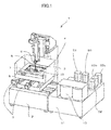
- FIG. 1 is a view illustrating a schematic configuration of a wire electric discharge machine.
- a working fluid tank 4 is disposed above a base 2 of a wire electric discharge machine 1 through a drive mechanism 3.
- a table 5 on which a workpiece (not shown) is removably secured is mounted in the working fluid tank 4.
- electro-discharge machining is made to the workpiece so that it is machined into a desired shape as a wire electrode 8 stretched between upper and lower head sections 6 and 7 moves relative to the workpiece.
- a working fluid such as water or oil
- the working fluid tank 4 the workpiece is immersed in the working fluid, and the working fluid is ejected for machining through upper and lower nozzles 9 and 10 attached to the upper and lower head sections 6 and 7, respectively, in order to discharge sludge produced during the machining and cool the wire electrode 8.
- the upper and lower nozzles 9 and 10 are immersed in the working fluid during the electric discharge machining lest the fluid scatter.
- the working fluid in the working fluid tank 4 is contaminated by the sludge produced during the machining, it is discharged into a sewage tank 11 through a drain outlet (not shown).
- the contaminated working fluid collected in the sewage tank 11 is pumped up by a filter pump 50 and delivered to a filter 13.
- the working fluid filtered by the filter 13 is collected in a clean fluid tank (not shown).
- a reservoir pump 51 pumps up the working fluid from the clean fluid tank and delivers it to the working fluid tank 4.
- a circulation pump 52 delivers the working fluid to a working fluid cooler (not shown) and an ionexchange resin (not shown), thereby adjusting the water temperature and specific resistance.
- a first working fluid pump 53a delivers the working fluid to the upper nozzle 9 so that the fluid is ejected from the upper nozzle 9.
- a second working fluid pump 53b delivers the working fluid to the lower nozzle 10 so that the fluid is ejected from the lower nozzle 10.
- FIG. 2 is a view illustrating the configurations of the upper head section 6 and an upper head support portion 16 of the wire electric discharge machine shown in FIG. 1 .
- the upper head section 6 comprises the upper nozzle 9 and an upper nozzle mounting portion 17 on which the upper nozzle 9 is mounted.
- the upper head section 6 is mounted on the upper head support portion 16.
- FIG. 3 is a view illustrating the configurations of the lower head section 7 and a lower head support portion 18 of the wire electric discharge machine shown in FIG. 1 .
- the lower head section 7 comprises the lower nozzle 10 and a lower nozzle mounting portion on which the lower nozzle 10 is mounted.
- the lower head section 7 is mounted on the lower head support portion 18.
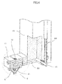
- FIG. 4 is a cross-section view illustrating a working fluid passage 20 in the upper head section 6 and the upper head support portion 16.
- An upper guide 21 is a member that supports the wire electrode 8.
- the wire electrode 8 is supplied with a machining current through a conductor 22.
- the working fluid forced by the pump 53a ( FIG. 1 ) is guided up to the upper head support portion 16 by a working fluid hose 23, which forms a part of the working fluid passage 20. Finally, the working fluid is ejected from the upper nozzle 9 through the passage 20 in the upper head support portion 16 and the upper head section 6.
- the working fluid hose 23 is connected to the working fluid passage 20 provided in the upper head support portion 16 by a joint 15.
- the hose 23 may be connected to the working fluid passage 20 provided in the upper head section 6 by a joint (not shown).
- FIG. 5 is a cross-section view illustrating a working fluid passage 24 in the lower head section 7 and the lower head support portion 18.
- a lower guide 25 is a member that supports the wire electrode 8.
- the wire electrode 8 is supplied with a machining current through a conductor 26.
- the working fluid forced by the pump 53b ( FIG. 1 ) is guided up to the lower head support portion 18 by a working fluid hose 27 and finally ejected from the lower nozzle 10 through the working fluid passage 24 provided in the lower head support portion 18 and the lower head section 7.
- the working fluid hose 27 is connected to the working fluid passage 24 provided in the lower head support portion 18 by a joint 35.
- the hose 27 may be connected to the working fluid passage 24 provided in the lower head section 7 by a joint (not shown).
- connection ports of a duct capable of transmitting the pressure of the working fluid forced by the pump are provided in positions (corresponding to the upper head section 6, upper head support portion 16, lower head section 7, and lower head support portion 18) relatively close to the upper and lower nozzles 9 and 10, where practically useful data can be obtained.
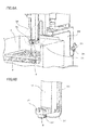
- FIG. 6A is a view illustrating an embodiment in which the duct capable of transmitting the pressure of the working fluid is connected to the upper nozzle 9 at the upper head section 6.
- FIG. 6B is an enlarged view of a portion designated by numeral 29 in FIG. 6A .
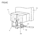
- FIG. 6C is an enlarged view, partially in section, of a portion designated by numeral 30 in FIG. 6A .
- a tube 31 for transmitting the working fluid pressure to a pressure sensor 34 and a joint 32 for connecting one end of the tube 31 to the upper nozzle 9 are used to measure the working fluid pressure in the upper nozzle 9.
- the joint 32 is secured to the upper nozzle 9 by means of a threaded hole 33 provided in the upper nozzle 9.
- the pressure sensor 34 is attached to the other end of the tube 31 by a joint 36.
- the pressure sensor 34 can detect the working fluid pressure in the upper nozzle 9 transmitted by a pressure transmission medium filled up in the tube 31.
- the installation position of the pressure sensor 34 can be freely selected by adjusting the length of the tube 31.
- the pressure sensor 34 can be installed at a distance from the noise sources and liquids, such as the working fluid, e.g., outside the working fluid tank 4.
- the pressure transmission medium that fills the tube 31 may be any material that does not affect the accuracy of practical pressure measurement. The easiest way is to directly use air in the tube as the transmission medium. Alternatively, the tube 31 may be previously filled with the working fluid so that the fluid can be used as the pressure transmission medium. In another alternative method, both the working fluid and air are used for the same purpose.
- a duct of the joint 32 on the side of the upper nozzle 9 is covered with a thin diaphragm of metal or the like capable of transmitting the working fluid pressure and the joint 36 and the tube 31 on the side of the pressure sensor 34 are filled with degradation-resistant silicone oil or the like lest the joint 32 and the tube 31 attached to the upper nozzle 9 be closed by foreign matter in the working fluid.
- the tube 31 may be of any material that does not affect the accuracy of practical pressure measurement. If leading of the tube 31 is to be minded, a highly flexible resin tube can be used as the tube 31. Furthermore, a metallic tube can be used if it is necessary to reduce degradation of the measurement accuracy by the expansion of the tube 31 or the like.
- FIG. 7A is a view illustrating an embodiment in which an upper head support portion 16 is provided directly with a duct capable of transmitting the pressure of a working fluid and a pressure sensor is attached to the upper head support portion 16.
- FIG. 7B is a sectional view corresponding to FIG. 7A and illustrating the duct capable of transmitting the working fluid pressure.
- the duct for transmitting the working fluid pressure is connected to a working fluid passage 20 in the upper head support portion 16, which is located slightly apart from the upper nozzle 9, without using the tube 31 as the duct.
- the upper head support portion 16 is provided directly with the duct for transmitting the working fluid pressure.
- the position of connection between the working fluid passage 20 and a duct 37 provided directly on the upper head support portion is located slightly apart from the upper nozzle 9, as shown in FIG. 7B , the measurement accuracy for the working fluid pressure in the upper nozzle 9 to be measured is somewhat reduced. If the duct is provided directly in the machine, however, the working fluid pressure can be easily measured without using an additional member, such as a joint or tube.
- a joint (not shown) may be connected in place of the pressure sensor 34 shown in FIGS. 7A and 7B , and a tube (not shown) may be provided extending from the joint, as shown in FIGS. 6A to 6C .
- a pressure sensor (not shown) may be installed on the distal end of the tube so that the working fluid pressure in the upper nozzle 9 can be detected by the pressure sensor.
- FIG. 8A is a view illustrating an embodiment in which a duct capable of transmitting a fluid pressure is connected to an upper nozzle mounting portion 17 at an upper head section 6.
- FIG. 8B is a sectional view of the upper nozzle mounting portion shown in FIG. 8A .
- the duct capable of transmitting the working fluid pressure is connected to the upper nozzle mounting portion 17 in the upper head section 6.
- a joint 32 is connected to the upper nozzle mounting portion 17.
- the nozzles are consumables and must be frequently detached for replacement. For the sake of measurement accuracy, it is the most effective to connect the tube 31 to the upper nozzle 9, as shown in FIGS. 6A to 6C , although it is not convenient for practical use.
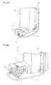
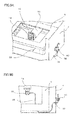
- FIG. 9A is a view illustrating an embodiment in which a duct capable of transmitting a fluid pressure is connected to a lower nozzle 10 in a lower head section 7.
- FIG. 9B is a top view of the lower head section 7 shown in FIG. 9A .
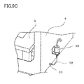
- FIG. 9C is an enlarged view of a pressure sensor mounting portion shown in FIG. 9A .
- FIGS. 9A to 9C show an example in which the pressure of a working fluid ejected from the lower nozzle 10 in the lower head section 7 is measured.
- a joint 39 is attached to the wall of a working fluid tank 4 so as to penetrate the wall, in order to lead a tube 38 extending from the lower nozzle 10 to the outside of the working fluid tank 4, and a pressure sensor 40 is installed outside the wall of the working fluid tank 4.
- the pressure sensor 40 is installed on a side portion of the working fluid tank 4.
- the tube 38 led out of the working fluid tank 4 may be extended and disposed side by side with the pressure sensor 34 for measuring the pressure of the working fluid ejected from the upper nozzle 9 in the upper head section 6. Since the pressure sensor 40 is installed outside the working fluid tank 4 in this embodiment, it can be prevented from being splashed with the working fluid.
- the position of detection of the working fluid pressure is separated from the position of installation of the pressure sensor 34.
- the pressure sensor 34 can be made less susceptible to noise due to electric discharge and can avoid being splashed with the working fluid. Consequently, there can be provided the high-performance, low-priced wire electric discharge machine 1.
Landscapes
- Engineering & Computer Science (AREA)
- Mechanical Engineering (AREA)
- Chemical & Material Sciences (AREA)
- Chemical Kinetics & Catalysis (AREA)
- Electrochemistry (AREA)
- Electrical Discharge Machining, Electrochemical Machining, And Combined Machining (AREA)
Abstract
Description
- The present invention relates to a wire electric discharge machine with means for detecting the pressure of a working fluid in the vicinity of a nozzle.
- In a wire electric discharge machine, a working fluid is introduced between a wire electrode and a workpiece by a nozzle. The value of the pressure of the working fluid ejected from the nozzle serves as an important index for various modes of control during machining, such as the maintenance of a stable machining state, detection of gaps between the nozzle and the workpiece, etc. In conventional wire electric discharge machines, the pressure of the working fluid is usually detected by means of a pressure sensor or the like installed in a pipe between the nozzle and a pump for discharging the working fluid.
- Japanese Patent Application Laid-Open No.
10-43947 U.S. Patent No. 5,045,663 discloses a wire electric discharge machine in which the pressure of a working fluid is detected by a pressure sensor connected to a duct extending from a jet pump to a jet nozzle. - If the pressure sensor is installed in a working fluid passage at a distance from a working fluid supply nozzle, it sometimes cannot correctly detect the pressure of the working fluid ejected from the nozzle, due to a pressure loss caused by the resistance of the passage from the nozzle to the installation position of the pressure sensor.
- In contrast, the pressure can be correctly detected if the pressure sensor is installed in the vicinity of the nozzle for ejecting the working fluid. Since the nozzle and its vicinity are located close to discharge points, however, the pressure sensor is liable to be affected by noise produced by electric discharge during machining. Thus, the pressure sensor cannot easily perform accurate pressure measurement. Further, the working fluid ejected from the nozzle or repelled by a workpiece produces a large splash. Thus, there is a problem that the pressure sensor must be waterproofed to avoid being affected by the splash of the working fluid.
- Accordingly, the present invention has been made to solve the above problems of the prior art, and it is an object of the invention to provide a wire electric discharge machine with an installation structure for a pressure sensor configured to accurately measure the pressure of a working fluid ejected from a nozzle and solve the problems of electric discharge noise and waterproof properties.
- A wire electric discharge machine according to the present invention is configured so that a wire electrode is stretched between an upper head section supported by an upper head support portion and a lower head section supported by a lower head support portion and serves to machine a workpiece. The wire electric discharge machine includes: a working fluid tank for storing a working fluid or preventing the working fluid from scattering; a pump configured to force the working fluid into the working fluid tank; a working fluid passage extending between an outlet of the pump and an outlet of a nozzle for ejecting the working fluid; a fluid pressure transmission duct capable of transmitting a fluid pressure; a connection port which connects the working fluid passage and the fluid pressure transmission duct and which is provided at the upper head section, the lower head section, the upper head support portion, or the lower head support portion; and a pressure sensor attached, outside the working fluid tank, to one end of the fluid pressure transmission duct, the other end of which is connected to the connection port.
- Each of the upper and lower head sections may comprise a wire guide portion supporting the wire electrode, a nozzle portion for ejecting the working fluid, a conductor portion configured to supply electricity to the wire electrode, and a working fluid duct portion for supplying the working fluid to the nozzle portion, the upper head support portion may comprise a member configured to move in the same direction as the upper head section as the upper head section is moved in a direction in which the wire electrode is stretched, and the lower head support portion may comprise a member which is disposed extending from outside the working fluid tank to the lower head section in order to move the lower head section relative to the workpiece.
- According to the present invention, there can be provided a wire electric discharge machine with an installation structure for a pressure sensor configured to accurately measure the pressure of a working fluid ejected from a nozzle and solve the problems of electric discharge noise and waterproof properties.
- The above and other objects and features of the present invention will be obvious from the ensuing description of embodiments with reference to the accompanying drawings, in which:
-
FIG. 1 is a view illustrating a schematic configuration of a wire electric discharge machine; -
FIG. 2 is a view illustrating the configurations of an upper head section and an upper head support portion of the wire electric discharge machine shown inFIG. 1 ; -
FIG. 3 is a view illustrating the configurations of a lower head section and a lower head support portion of the wire electric discharge machine shown inFIG. 1 ; -
FIG. 4 is a cross-section view illustrating a working fluid passage in the upper head section and the upper head support portion; -
FIG. 5 is a cross-section view illustrating a working fluid passage in the lower head section and the lower head support portion; -
FIG. 6A is a view illustrating an embodiment in which a duct capable of transmitting the pressure of a working fluid is connected to a nozzle in the upper head section; -
FIG. 6B is an enlarged view of a portion designated bynumeral 29 inFIG. 6A ; -
FIG. 6C is an enlarged view, partially in section, of a portion designated bynumeral 30 inFIG. 6A ; -
FIG. 7A is a view illustrating an embodiment in which an upper head support portion is provided directly with a duct capable of transmitting the pressure of a working fluid and a pressure sensor is attached to the upper head support portion; -
FIG. 7B is a sectional view corresponding toFIG. 7A and illustrating the duct capable of transmitting the working fluid pressure; -
FIG. 8A is a view illustrating an embodiment in which a duct capable of transmitting a fluid pressure is connected to an upper nozzle mounting portion in an upper head section; -
FIG. 8B is a sectional view of the upper nozzle mounting portion shown inFIG. 8A ; -
FIG. 9A is a view illustrating an embodiment in which a duct capable of transmitting a fluid pressure is connected to a lower nozzle in a lower head section; -
FIG. 9B is a top view of thelower head section 7 shown inFIG. 9A ; and -
FIG. 9C is an enlarged view of a pressure sensor mounting portion shown inFIG. 9A . -
FIG. 1 is a view illustrating a schematic configuration of a wire electric discharge machine. - A working
fluid tank 4 is disposed above abase 2 of a wireelectric discharge machine 1 through adrive mechanism 3. A table 5 on which a workpiece (not shown) is removably secured is mounted in theworking fluid tank 4. Thedrive mechanism 3, which is composed of a servomotor or the like, serves to move theworking fluid tank 4 in two horizontal axial directions. Thus, electro-discharge machining is made to the workpiece so that it is machined into a desired shape as awire electrode 8 stretched between upper andlower head sections - In normal wire electric discharge machining, a working fluid, such as water or oil, is stored in the
working fluid tank 4, the workpiece is immersed in the working fluid, and the working fluid is ejected for machining through upper andlower nozzles lower head sections wire electrode 8. The upper andlower nozzles - Since the working fluid in the
working fluid tank 4 is contaminated by the sludge produced during the machining, it is discharged into asewage tank 11 through a drain outlet (not shown). The contaminated working fluid collected in thesewage tank 11 is pumped up by afilter pump 50 and delivered to afilter 13. The working fluid filtered by thefilter 13 is collected in a clean fluid tank (not shown). Areservoir pump 51 pumps up the working fluid from the clean fluid tank and delivers it to the workingfluid tank 4. Acirculation pump 52 delivers the working fluid to a working fluid cooler (not shown) and an ionexchange resin (not shown), thereby adjusting the water temperature and specific resistance. A first workingfluid pump 53a delivers the working fluid to theupper nozzle 9 so that the fluid is ejected from theupper nozzle 9. A second workingfluid pump 53b delivers the working fluid to thelower nozzle 10 so that the fluid is ejected from thelower nozzle 10. -
FIG. 2 is a view illustrating the configurations of theupper head section 6 and an upperhead support portion 16 of the wire electric discharge machine shown inFIG. 1 . - The
upper head section 6 comprises theupper nozzle 9 and an uppernozzle mounting portion 17 on which theupper nozzle 9 is mounted. Theupper head section 6 is mounted on the upperhead support portion 16. -
FIG. 3 is a view illustrating the configurations of thelower head section 7 and a lowerhead support portion 18 of the wire electric discharge machine shown inFIG. 1 . - The
lower head section 7 comprises thelower nozzle 10 and a lower nozzle mounting portion on which thelower nozzle 10 is mounted. Thelower head section 7 is mounted on the lowerhead support portion 18. -
FIG. 4 is a cross-section view illustrating a workingfluid passage 20 in theupper head section 6 and the upperhead support portion 16. - An
upper guide 21 is a member that supports thewire electrode 8. Thewire electrode 8 is supplied with a machining current through aconductor 22. The working fluid forced by thepump 53a (FIG. 1 ) is guided up to the upperhead support portion 16 by a workingfluid hose 23, which forms a part of the workingfluid passage 20. Finally, the working fluid is ejected from theupper nozzle 9 through thepassage 20 in the upperhead support portion 16 and theupper head section 6. - In
FIG. 4 , the workingfluid hose 23 is connected to the workingfluid passage 20 provided in the upperhead support portion 16 by a joint 15. Alternatively, however, thehose 23 may be connected to the workingfluid passage 20 provided in theupper head section 6 by a joint (not shown). -
FIG. 5 is a cross-section view illustrating a workingfluid passage 24 in thelower head section 7 and the lowerhead support portion 18. - A
lower guide 25 is a member that supports thewire electrode 8. Thewire electrode 8 is supplied with a machining current through aconductor 26. As in the case of theupper head section 6, the working fluid forced by thepump 53b (FIG. 1 ) is guided up to the lowerhead support portion 18 by a workingfluid hose 27 and finally ejected from thelower nozzle 10 through the workingfluid passage 24 provided in the lowerhead support portion 18 and thelower head section 7. - In
FIG. 5 , the workingfluid hose 27 is connected to the workingfluid passage 24 provided in the lowerhead support portion 18 by a joint 35. Alternatively, however, thehose 27 may be connected to the workingfluid passage 24 provided in thelower head section 7 by a joint (not shown). - The configurations described above are the same as those of a conventional wire electric discharge machine. The influence of pressure losses in the working fluid passage 20 (
FIG. 4 ) and the working fluid passage 24 (FIG. 5 ) increases with distance from the upper andlower nozzles upper head section 6, upperhead support portion 16,lower head section 7, and lower head support portion 18) relatively close to the upper andlower nozzles -
FIG. 6A is a view illustrating an embodiment in which the duct capable of transmitting the pressure of the working fluid is connected to theupper nozzle 9 at theupper head section 6.FIG. 6B is an enlarged view of a portion designated by numeral 29 inFIG. 6A .FIG. 6C is an enlarged view, partially in section, of a portion designated by numeral 30 inFIG. 6A . - In the embodiment of the present invention shown in
FIGS. 6A to 6C , atube 31 for transmitting the working fluid pressure to apressure sensor 34 and a joint 32 for connecting one end of thetube 31 to theupper nozzle 9 are used to measure the working fluid pressure in theupper nozzle 9. The joint 32 is secured to theupper nozzle 9 by means of a threadedhole 33 provided in theupper nozzle 9. - As shown in
FIG. 6A , thepressure sensor 34 is attached to the other end of thetube 31 by a joint 36. Thepressure sensor 34 can detect the working fluid pressure in theupper nozzle 9 transmitted by a pressure transmission medium filled up in thetube 31. - In the wire
electric discharge machine 1, discharge points and power cables constitute strong sources of noise. For accurate measurement of the working fluid pressure, therefore, it is essential to keep electronic devices, such as the pressure sensor, away from the noise sources as much as possible. Further, the electronic devices are seldom waterproof and are more costly than regular components if they are waterproof, so that they should be located as far from a part that tends to have contact with liquid as possible. - With the construction shown in
FIGS. 6A to 6C , the installation position of thepressure sensor 34 can be freely selected by adjusting the length of thetube 31. Thus, thepressure sensor 34 can be installed at a distance from the noise sources and liquids, such as the working fluid, e.g., outside the workingfluid tank 4. - The pressure transmission medium that fills the
tube 31 may be any material that does not affect the accuracy of practical pressure measurement. The easiest way is to directly use air in the tube as the transmission medium. Alternatively, thetube 31 may be previously filled with the working fluid so that the fluid can be used as the pressure transmission medium. In another alternative method, both the working fluid and air are used for the same purpose. - Also, there is a method in which a duct of the joint 32 on the side of the
upper nozzle 9 is covered with a thin diaphragm of metal or the like capable of transmitting the working fluid pressure and the joint 36 and thetube 31 on the side of thepressure sensor 34 are filled with degradation-resistant silicone oil or the like lest the joint 32 and thetube 31 attached to theupper nozzle 9 be closed by foreign matter in the working fluid. Further, thetube 31 may be of any material that does not affect the accuracy of practical pressure measurement. If leading of thetube 31 is to be minded, a highly flexible resin tube can be used as thetube 31. Furthermore, a metallic tube can be used if it is necessary to reduce degradation of the measurement accuracy by the expansion of thetube 31 or the like. -
FIG. 7A is a view illustrating an embodiment in which an upperhead support portion 16 is provided directly with a duct capable of transmitting the pressure of a working fluid and a pressure sensor is attached to the upperhead support portion 16.FIG. 7B is a sectional view corresponding toFIG. 7A and illustrating the duct capable of transmitting the working fluid pressure. - In this embodiment, the duct for transmitting the working fluid pressure is connected to a working
fluid passage 20 in the upperhead support portion 16, which is located slightly apart from theupper nozzle 9, without using thetube 31 as the duct. Thus, the upperhead support portion 16 is provided directly with the duct for transmitting the working fluid pressure. - Since the position of connection between the working
fluid passage 20 and aduct 37 provided directly on the upper head support portion is located slightly apart from theupper nozzle 9, as shown inFIG. 7B , the measurement accuracy for the working fluid pressure in theupper nozzle 9 to be measured is somewhat reduced. If the duct is provided directly in the machine, however, the working fluid pressure can be easily measured without using an additional member, such as a joint or tube. - Alternatively, a joint (not shown) may be connected in place of the
pressure sensor 34 shown inFIGS. 7A and7B , and a tube (not shown) may be provided extending from the joint, as shown inFIGS. 6A to 6C . Further, a pressure sensor (not shown) may be installed on the distal end of the tube so that the working fluid pressure in theupper nozzle 9 can be detected by the pressure sensor. -
FIG. 8A is a view illustrating an embodiment in which a duct capable of transmitting a fluid pressure is connected to an uppernozzle mounting portion 17 at anupper head section 6.FIG. 8B is a sectional view of the upper nozzle mounting portion shown inFIG. 8A . - In the embodiment shown in
FIGS. 8A and 8B , the duct capable of transmitting the working fluid pressure is connected to the uppernozzle mounting portion 17 in theupper head section 6. In this embodiment, unlike the embodiment ofFIGS. 6A to 6C in which the joint 32 is connected to theupper nozzle 9, a joint 32 is connected to the uppernozzle mounting portion 17. In many of conventional wire electric discharge machines, the nozzles are consumables and must be frequently detached for replacement. For the sake of measurement accuracy, it is the most effective to connect thetube 31 to theupper nozzle 9, as shown inFIGS. 6A to 6C , although it is not convenient for practical use. For making the measurement accuracy for the working fluid pressure and the convenience of practical use compatible, therefore, it is effective to provide the duct in a member that is detached less frequently than theupper nozzle 9 and locate it as close to theupper nozzle 9 as possible, as in the embodiment shown inFIGS. 8A and 8B . -
FIG. 9A is a view illustrating an embodiment in which a duct capable of transmitting a fluid pressure is connected to alower nozzle 10 in alower head section 7.FIG. 9B is a top view of thelower head section 7 shown inFIG. 9A .FIG. 9C is an enlarged view of a pressure sensor mounting portion shown inFIG. 9A . -
FIGS. 9A to 9C show an example in which the pressure of a working fluid ejected from thelower nozzle 10 in thelower head section 7 is measured. In the example ofFIGS. 9A to 9C , a joint 39 is attached to the wall of a workingfluid tank 4 so as to penetrate the wall, in order to lead atube 38 extending from thelower nozzle 10 to the outside of the workingfluid tank 4, and apressure sensor 40 is installed outside the wall of the workingfluid tank 4. Thus, thepressure sensor 40 is installed on a side portion of the workingfluid tank 4. Alternatively, thetube 38 led out of the workingfluid tank 4 may be extended and disposed side by side with thepressure sensor 34 for measuring the pressure of the working fluid ejected from theupper nozzle 9 in theupper head section 6. Since thepressure sensor 40 is installed outside the workingfluid tank 4 in this embodiment, it can be prevented from being splashed with the working fluid. - Thus, in order to accurately measure the pressure of the working fluid ejected from the upper and
lower nozzles electric discharge machine 1, the position of detection of the working fluid pressure is separated from the position of installation of thepressure sensor 34. In this way, thepressure sensor 34 can be made less susceptible to noise due to electric discharge and can avoid being splashed with the working fluid. Consequently, there can be provided the high-performance, low-priced wireelectric discharge machine 1.
Claims (2)
- A wire electric discharge machine, in which a wire electrode is stretched between an upper head section supported by an upper head support portion and a lower head section supported by a lower head support portion and serves to machine a workpiece, the wire electric discharge machine comprising:a working fluid tank for storing a working fluid or preventing the working fluid from scattering;a pump configured to force the working fluid into the working fluid tank;a working fluid passage extending between an outlet of the pump and an outlet of a nozzle for ejecting the working fluid;a fluid pressure transmission duct capable of transmitting a fluid pressure;a connection port which connects the working fluid passage and the fluid pressure transmission duct and which is provided at the upper head section, the lower head section, the upper head support portion, or the lower head support portion; anda pressure sensor attached, outside the working fluid tank, to one end of the fluid pressure transmission duct, the other end of which is connected to the connection port.
- The wire electric discharge machine according to claim 1, wherein
each of the upper and lower head sections comprises a wire guide portion supporting the wire electrode, a nozzle portion for ejecting the working fluid, a conductor portion configured to supply electricity to the wire electrode, and a working fluid duct portion for supplying the working fluid to the nozzle portion,
the upper head support portion comprises a member configured to move in the same direction as the upper head section as the upper head section is moved in a direction in which the wire electrode is stretched, and
the lower head support portion comprises a member which is disposed extending from outside the working fluid tank to the lower head section in order to move the lower head section relative to the workpiece.
Applications Claiming Priority (1)
| Application Number | Priority Date | Filing Date | Title |
|---|---|---|---|
| JP2013218578A JP2015080826A (en) | 2013-10-21 | 2013-10-21 | Wire electric discharge machine including means for detecting fluid pressure |
Publications (2)
| Publication Number | Publication Date |
|---|---|
| EP2862660A2 true EP2862660A2 (en) | 2015-04-22 |
| EP2862660A3 EP2862660A3 (en) | 2015-05-27 |
Family
ID=51399570
Family Applications (1)
| Application Number | Title | Priority Date | Filing Date |
|---|---|---|---|
| EP14182593.5A Withdrawn EP2862660A3 (en) | 2013-10-21 | 2014-08-28 | Wire electric discharge machine with means for detecting fluid pressure |
Country Status (4)
| Country | Link |
|---|---|
| US (1) | US20150108093A1 (en) |
| EP (1) | EP2862660A3 (en) |
| JP (1) | JP2015080826A (en) |
| CN (1) | CN104551275A (en) |
Cited By (1)
| Publication number | Priority date | Publication date | Assignee | Title |
|---|---|---|---|---|
| CN116493690A (en) * | 2023-06-27 | 2023-07-28 | 泰州市特锐数控机床有限公司 | Precise medium-speed wire cutting machine tool |
Families Citing this family (4)
| Publication number | Priority date | Publication date | Assignee | Title |
|---|---|---|---|---|
| BE1025016B1 (en) * | 2017-03-02 | 2018-10-03 | Safran Aero Boosters S.A. | MACHINE AND METHOD FOR ELECTROEROSION MACHINING OF GEROTOR PUMP |
| JP6707303B2 (en) * | 2017-12-15 | 2020-06-10 | 株式会社ソディック | Wire cut electrical discharge machine |
| JP1680858S (en) * | 2020-04-20 | 2021-03-15 | ||
| CN112404617B (en) * | 2020-11-18 | 2021-11-19 | 上海交通大学 | Electricity liquid allies oneself with confession device |
Citations (2)
| Publication number | Priority date | Publication date | Assignee | Title |
|---|---|---|---|---|
| US5045663A (en) | 1990-02-27 | 1991-09-03 | Elox Corporation | System for control of flushing flow in a spark discharge (EDM) machine |
| JPH1043947A (en) | 1996-07-26 | 1998-02-17 | Japax Inc | Work liquid supply nozzle and work liquid jet device using this |
Family Cites Families (8)
| Publication number | Priority date | Publication date | Assignee | Title |
|---|---|---|---|---|
| US4481095A (en) * | 1982-02-03 | 1984-11-06 | Inoue-Japax Research Incorporated | Apparatus for supplying a working fluid and a wire electrode to a work portion of a wire-cut electrical discharge machine |
| DE3317826C2 (en) * | 1982-05-19 | 1994-04-07 | Amada Co | Cutting wire spark erosion machine |
| JPH0716825B2 (en) * | 1986-08-18 | 1995-03-01 | フアナツク株式会社 | Wire electric discharge machine |
| CH670061A5 (en) * | 1986-11-26 | 1989-05-12 | Charmilles Technologies | |
| JPH01177918A (en) * | 1988-01-09 | 1989-07-14 | Fanuc Ltd | Processing liquid flow controller in wire cut discharge processor |
| EP0383370B1 (en) * | 1989-01-13 | 1995-07-26 | Charmilles Technologies S.A. | Control and method for electroerosion wire cutting avoiding wire breakage |
| CN1137796C (en) * | 1999-08-20 | 2004-02-11 | 三菱电机株式会社 | Wire cutting processing device |
| CN1121295C (en) * | 1999-11-17 | 2003-09-17 | 沙迪克株式会社 | Liquid feeder for electrodischarge machining |
-
2013
- 2013-10-21 JP JP2013218578A patent/JP2015080826A/en active Pending
-
2014
- 2014-08-28 EP EP14182593.5A patent/EP2862660A3/en not_active Withdrawn
- 2014-10-17 CN CN201410553095.XA patent/CN104551275A/en active Pending
- 2014-10-20 US US14/518,004 patent/US20150108093A1/en not_active Abandoned
Patent Citations (2)
| Publication number | Priority date | Publication date | Assignee | Title |
|---|---|---|---|---|
| US5045663A (en) | 1990-02-27 | 1991-09-03 | Elox Corporation | System for control of flushing flow in a spark discharge (EDM) machine |
| JPH1043947A (en) | 1996-07-26 | 1998-02-17 | Japax Inc | Work liquid supply nozzle and work liquid jet device using this |
Cited By (2)
| Publication number | Priority date | Publication date | Assignee | Title |
|---|---|---|---|---|
| CN116493690A (en) * | 2023-06-27 | 2023-07-28 | 泰州市特锐数控机床有限公司 | Precise medium-speed wire cutting machine tool |
| CN116493690B (en) * | 2023-06-27 | 2023-08-29 | 泰州市特锐数控机床有限公司 | Precise medium-speed wire cutting machine tool |
Also Published As
| Publication number | Publication date |
|---|---|
| CN104551275A (en) | 2015-04-29 |
| JP2015080826A (en) | 2015-04-27 |
| US20150108093A1 (en) | 2015-04-23 |
| EP2862660A3 (en) | 2015-05-27 |
Similar Documents
| Publication | Publication Date | Title |
|---|---|---|
| US20150108093A1 (en) | Wire electric discharge machine with means for detecting fluid pressure | |
| US8292035B2 (en) | Oil/air lubrication system | |
| US20140144884A1 (en) | Small-hole electrical discharge machining device | |
| JP7395105B2 (en) | Coolant quality management system and coolant quality detection unit | |
| EP3667262B1 (en) | Fluid sensor assembly | |
| US9752916B2 (en) | Probe for monitoring the surface level of a fluid in a vessel and a method of installing the probe in the vessel | |
| EP3315784B1 (en) | Submersible pump unit and method of operating a submersible pump unit | |
| CN101723063A (en) | Controlled self-lifting floating body | |
| JP5039002B2 (en) | Wire cut electric discharge machining apparatus, wire guide assembly and cleaning method thereof | |
| JP6993679B2 (en) | Lubricating oil sensor head and sensor system | |
| JP2016200597A (en) | Sensor, drive device component including sensor, drive device including drive device component, and determination method | |
| JP2008273168A5 (en) | ||
| CN101285819B (en) | Pipeline section type automatic erasing moisture analyzer | |
| CN213516100U (en) | Temperature sensor with protection device at front end | |
| JP4905833B2 (en) | Inner diameter measuring device and inner diameter measuring method | |
| JP2020159163A (en) | Water faucet device | |
| CN211501592U (en) | Oil temperature and oil level monitoring device of speed reducer | |
| KR20210015310A (en) | Device for discharging liquid | |
| CN104018909B (en) | A kind of engine oil scaleplate pipe and motor | |
| JP7329176B2 (en) | faucet device | |
| CN208663290U (en) | Lathe with lubricating arrangement | |
| CN1864903B (en) | Chemical Etching Assisted EDM Head | |
| CN217504644U (en) | Self-centering roughness measuring device and measuring machine | |
| KR20150072039A (en) | Electrostatic capacitance type system for sensing liquid level | |
| CN212391092U (en) | Liquid level detection system and unmanned aerial vehicle thereof |
Legal Events
| Date | Code | Title | Description |
|---|---|---|---|
| PUAI | Public reference made under article 153(3) epc to a published international application that has entered the european phase |
Free format text: ORIGINAL CODE: 0009012 |
|
| 17P | Request for examination filed |
Effective date: 20140828 |
|
| AK | Designated contracting states |
Kind code of ref document: A2 Designated state(s): AL AT BE BG CH CY CZ DE DK EE ES FI FR GB GR HR HU IE IS IT LI LT LU LV MC MK MT NL NO PL PT RO RS SE SI SK SM TR |
|
| AX | Request for extension of the european patent |
Extension state: BA ME |
|
| PUAL | Search report despatched |
Free format text: ORIGINAL CODE: 0009013 |
|
| AK | Designated contracting states |
Kind code of ref document: A3 Designated state(s): AL AT BE BG CH CY CZ DE DK EE ES FI FR GB GR HR HU IE IS IT LI LT LU LV MC MK MT NL NO PL PT RO RS SE SI SK SM TR |
|
| AX | Request for extension of the european patent |
Extension state: BA ME |
|
| RIC1 | Information provided on ipc code assigned before grant |
Ipc: B23H 7/10 20060101AFI20150420BHEP Ipc: B23H 1/10 20060101ALN20150420BHEP |
|
| STAA | Information on the status of an ep patent application or granted ep patent |
Free format text: STATUS: THE APPLICATION IS DEEMED TO BE WITHDRAWN |
|
| 18D | Application deemed to be withdrawn |
Effective date: 20151128 |