EP2862588A1 - Drug injection device - Google Patents
Drug injection device Download PDFInfo
- Publication number
- EP2862588A1 EP2862588A1 EP20130804334 EP13804334A EP2862588A1 EP 2862588 A1 EP2862588 A1 EP 2862588A1 EP 20130804334 EP20130804334 EP 20130804334 EP 13804334 A EP13804334 A EP 13804334A EP 2862588 A1 EP2862588 A1 EP 2862588A1
- Authority
- EP
- European Patent Office
- Prior art keywords
- cover
- mounting portion
- pharmaceutical
- injection needle
- opening
- Prior art date
- Legal status (The legal status is an assumption and is not a legal conclusion. Google has not performed a legal analysis and makes no representation as to the accuracy of the status listed.)
- Granted
Links
- 0 C*1C2C(*)*(CCC3)C3CC12 Chemical compound C*1C2C(*)*(CCC3)C3CC12 0.000 description 1
Images











Classifications
-
- A—HUMAN NECESSITIES
- A61—MEDICAL OR VETERINARY SCIENCE; HYGIENE
- A61M—DEVICES FOR INTRODUCING MEDIA INTO, OR ONTO, THE BODY; DEVICES FOR TRANSDUCING BODY MEDIA OR FOR TAKING MEDIA FROM THE BODY; DEVICES FOR PRODUCING OR ENDING SLEEP OR STUPOR
- A61M5/00—Devices for bringing media into the body in a subcutaneous, intra-vascular or intramuscular way; Accessories therefor, e.g. filling or cleaning devices, arm-rests
- A61M5/178—Syringes
- A61M5/20—Automatic syringes, e.g. with automatically actuated piston rod, with automatic needle injection, filling automatically
-
- A—HUMAN NECESSITIES
- A61—MEDICAL OR VETERINARY SCIENCE; HYGIENE
- A61M—DEVICES FOR INTRODUCING MEDIA INTO, OR ONTO, THE BODY; DEVICES FOR TRANSDUCING BODY MEDIA OR FOR TAKING MEDIA FROM THE BODY; DEVICES FOR PRODUCING OR ENDING SLEEP OR STUPOR
- A61M5/00—Devices for bringing media into the body in a subcutaneous, intra-vascular or intramuscular way; Accessories therefor, e.g. filling or cleaning devices, arm-rests
- A61M5/178—Syringes
- A61M5/24—Ampoule syringes, i.e. syringes with needle for use in combination with replaceable ampoules or carpules, e.g. automatic
- A61M2005/2403—Ampoule inserted into the ampoule holder
- A61M2005/2414—Ampoule inserted into the ampoule holder from the side
-
- A—HUMAN NECESSITIES
- A61—MEDICAL OR VETERINARY SCIENCE; HYGIENE
- A61M—DEVICES FOR INTRODUCING MEDIA INTO, OR ONTO, THE BODY; DEVICES FOR TRANSDUCING BODY MEDIA OR FOR TAKING MEDIA FROM THE BODY; DEVICES FOR PRODUCING OR ENDING SLEEP OR STUPOR
- A61M5/00—Devices for bringing media into the body in a subcutaneous, intra-vascular or intramuscular way; Accessories therefor, e.g. filling or cleaning devices, arm-rests
- A61M5/178—Syringes
- A61M5/31—Details
- A61M2005/3103—Leak prevention means for distal end of syringes, i.e. syringe end for mounting a needle
- A61M2005/3104—Caps for syringes without needle
-
- A—HUMAN NECESSITIES
- A61—MEDICAL OR VETERINARY SCIENCE; HYGIENE
- A61M—DEVICES FOR INTRODUCING MEDIA INTO, OR ONTO, THE BODY; DEVICES FOR TRANSDUCING BODY MEDIA OR FOR TAKING MEDIA FROM THE BODY; DEVICES FOR PRODUCING OR ENDING SLEEP OR STUPOR
- A61M5/00—Devices for bringing media into the body in a subcutaneous, intra-vascular or intramuscular way; Accessories therefor, e.g. filling or cleaning devices, arm-rests
- A61M5/178—Syringes
- A61M5/31—Details
- A61M2005/3125—Details specific display means, e.g. to indicate dose setting
-
- A—HUMAN NECESSITIES
- A61—MEDICAL OR VETERINARY SCIENCE; HYGIENE
- A61M—DEVICES FOR INTRODUCING MEDIA INTO, OR ONTO, THE BODY; DEVICES FOR TRANSDUCING BODY MEDIA OR FOR TAKING MEDIA FROM THE BODY; DEVICES FOR PRODUCING OR ENDING SLEEP OR STUPOR
- A61M2205/00—General characteristics of the apparatus
- A61M2205/18—General characteristics of the apparatus with alarm
-
- A—HUMAN NECESSITIES
- A61—MEDICAL OR VETERINARY SCIENCE; HYGIENE
- A61M—DEVICES FOR INTRODUCING MEDIA INTO, OR ONTO, THE BODY; DEVICES FOR TRANSDUCING BODY MEDIA OR FOR TAKING MEDIA FROM THE BODY; DEVICES FOR PRODUCING OR ENDING SLEEP OR STUPOR
- A61M2205/00—General characteristics of the apparatus
- A61M2205/50—General characteristics of the apparatus with microprocessors or computers
- A61M2205/52—General characteristics of the apparatus with microprocessors or computers with memories providing a history of measured variating parameters of apparatus or patient
-
- A—HUMAN NECESSITIES
- A61—MEDICAL OR VETERINARY SCIENCE; HYGIENE
- A61M—DEVICES FOR INTRODUCING MEDIA INTO, OR ONTO, THE BODY; DEVICES FOR TRANSDUCING BODY MEDIA OR FOR TAKING MEDIA FROM THE BODY; DEVICES FOR PRODUCING OR ENDING SLEEP OR STUPOR
- A61M2205/00—General characteristics of the apparatus
- A61M2205/58—Means for facilitating use, e.g. by people with impaired vision
- A61M2205/581—Means for facilitating use, e.g. by people with impaired vision by audible feedback
-
- A—HUMAN NECESSITIES
- A61—MEDICAL OR VETERINARY SCIENCE; HYGIENE
- A61M—DEVICES FOR INTRODUCING MEDIA INTO, OR ONTO, THE BODY; DEVICES FOR TRANSDUCING BODY MEDIA OR FOR TAKING MEDIA FROM THE BODY; DEVICES FOR PRODUCING OR ENDING SLEEP OR STUPOR
- A61M2205/00—General characteristics of the apparatus
- A61M2205/82—Internal energy supply devices
- A61M2205/8206—Internal energy supply devices battery-operated
-
- A—HUMAN NECESSITIES
- A61—MEDICAL OR VETERINARY SCIENCE; HYGIENE
- A61M—DEVICES FOR INTRODUCING MEDIA INTO, OR ONTO, THE BODY; DEVICES FOR TRANSDUCING BODY MEDIA OR FOR TAKING MEDIA FROM THE BODY; DEVICES FOR PRODUCING OR ENDING SLEEP OR STUPOR
- A61M5/00—Devices for bringing media into the body in a subcutaneous, intra-vascular or intramuscular way; Accessories therefor, e.g. filling or cleaning devices, arm-rests
- A61M5/178—Syringes
- A61M5/24—Ampoule syringes, i.e. syringes with needle for use in combination with replaceable ampoules or carpules, e.g. automatic
-
- A—HUMAN NECESSITIES
- A61—MEDICAL OR VETERINARY SCIENCE; HYGIENE
- A61M—DEVICES FOR INTRODUCING MEDIA INTO, OR ONTO, THE BODY; DEVICES FOR TRANSDUCING BODY MEDIA OR FOR TAKING MEDIA FROM THE BODY; DEVICES FOR PRODUCING OR ENDING SLEEP OR STUPOR
- A61M5/00—Devices for bringing media into the body in a subcutaneous, intra-vascular or intramuscular way; Accessories therefor, e.g. filling or cleaning devices, arm-rests
- A61M5/178—Syringes
- A61M5/31—Details
- A61M5/315—Pistons; Piston-rods; Guiding, blocking or restricting the movement of the rod or piston; Appliances on the rod for facilitating dosing ; Dosing mechanisms
- A61M5/31565—Administration mechanisms, i.e. constructional features, modes of administering a dose
- A61M5/31566—Means improving security or handling thereof
- A61M5/31573—Accuracy improving means
- A61M5/31575—Accuracy improving means using scaling up or down transmissions, e.g. gearbox
Definitions
- the present invention relates to a pharmaceutical injection device for injecting a pharmaceutical into a human body, etc.
- a pharmaceutical injection device typically comprises a main body case having an injection needle mounting portion at a first end, a pharmaceutical syringe mounting portion provided inside the main body case, a piston provided movably with respect to a pharmaceutical syringe mounted to the pharmaceutical syringe mounting portion, and a drive mechanism for driving the piston.
- the pharmaceutical syringe is mounted to the pharmaceutical syringe mounting portion, and then the injection needle is mounted to the injection needle mounting portion. After this, the injection needle pierces the skin of the patient, and then a packing inside the pharmaceutical syringe is pushed by the piston under drive from the drive mechanism, which injects the pharmaceutical inside the pharmaceutical syringe through the injection needle and into the patient's body.
- a cover that covers the injection needle mounting portion is removably mounted to the main body case in order to prevent soiling of the injection needle mounting portion (see Patent Literature 1, for example).
- Patent Literature 1 Japanese Unexamined Patent Application Publication (Translation of PCT Application) No. 2008-514249
- the cover that covers the injection needle mounting portion is removably mounted to the main body case. This prevents the injection needle mounting portion from being soiled, but since the cover can be removed from the main body case, the cover may be lost, so this system can be inconvenient to use.
- the pharmaceutical injection device of the present invention comprises a main body case, a pharmaceutical syringe mounting portion, a piston, a drive mechanism, and a cover.
- the main body case has at a first end an injection needle mounting portion to which an injection needle is mounted.
- the pharmaceutical syringe mounting portion is provided inside the main body case, and a pharmaceutical syringe is mounted thereto.
- the piston is provided movably with respect to the pharmaceutical syringe that is mounted to the pharmaceutical syringe mounting portion.
- the drive mechanism drives the piston.
- the cover covers the pharmaceutical syringe mounting portion in an openable and closeable state so as to expose the injection needle mounting portion to the outside, while the cover is still attached to the first end side of the main body case.
- the cover is provided on the first end side of the main body case in an openable and closeable state so as to cover the injection needle mounting portion. That is, since the cover is always mounted to the main body case, it will not be lost, making the device more convenient to use.
- the pharmaceutical injection device in this embodiment comprises a columnar main body case 1, an injection needle mounting portion 2 provided on the first end side thereof (the piercing side), and a pharmaceutical syringe mounting portion 3 provided inside the main body case 1.
- the pharmaceutical syringe mounting portion 3 can stick out from the main body case 1, and as shown in FIG. 1A , a pharmaceutical syringe 4 is mounted to it in a state in which it has been pulled out from the main body case 1. After this, as shown in FIG. 1B , the pharmaceutical syringe mounting portion 3 is pushed into the main body case 1, so that the pharmaceutical syringe 4 is disposed at a specific position within the main body case 1 as shown in FIG. 3 .
- a piston 5 is disposed in a state of being movable with respect to the pharmaceutical syringe 4 mounted inside the pharmaceutical syringe mounting portion 3.
- a motor (drive mechanism) 8 is linked to the piston 5 via a piston feed screw (drive mechanism) 6 and a gear (drive mechanism) 7. Therefore, when the motor 8 is actuated, the piston 5 is pushed to the pharmaceutical syringe mounting portion 3 side via the gear 7 and the piston feed screw 6. This allows the pharmaceutical inside the pharmaceutical syringe 4 to be injected into a patient's body, etc. (discussed in detail below).
- the pharmaceutical syringe 4 is usually in the form of a circular cylinder, and a gasket (not shown) that is pushed in by the piston 5 is disposed in the interior on the rear end side (the piston 5 side) in the piercing direction.
- a packing (not shown) at which the rear end side (the piston 5 side) of an injection needle 9 is pushed in is disposed on the distal end side (the first end side) of the pharmaceutical syringe 4.
- the distal end side (the opposite side from the piston 5) of the pharmaceutical syringe 4 becomes the injection needle mounting portion 2.
- the injection needle 9 is mounted to the injection needle mounting portion 2, the pharmaceutical in the pharmaceutical syringe 4 is injected through the injection needle 9 into the body.
- the battery 10 shown in FIG. 3 is provided to supply power to the various components.
- a power button 11, a pharmaceutical injection button 12, a setting button 13 for setting pharmaceutical injection quantities and so forth, and a display section 14 that displays the operating state and so forth are provided to the front of the main body case 1 (see FIGS. 1A, 1B , and FIGS. 2A , 2B ).
- FIG. 4 shows the control blocks of this pharmaceutical injection device.
- the battery 10, the power button 11, the pharmaceutical injection button 12, the setting button 13, and the display section 14 are connected to a controller 15.
- the controller 15 is connected to the motor 8 via a drive circuit 16. Consequently, the amount of rotation of the motor 8, that is, the amount the piston 5 is pushed in, is sensed by an encoder 17 and a piston movement distance sensor 18.
- the rotational control of the motor 8 is performed by a motor rotation controller 19, via the drive circuit 16. Over-current in the motor 8 is detected by an over-current detection circuit 20. Thus, the drive of the motor 8 is quickly stopped when an abnormality due to over-current is detected.
- a central processing unit 21 and a ROM 22 containing programs are provided inside the controller 15.
- the controller 15 is also connected to a memory 23 that stores operational states, setting data, injection history, and so forth, and a sounder 24 that emits operating sounds, warning sounds, audio output, and so forth.
- the injection needle mounting portion 2 (also serves as the distal end side of the pharmaceutical syringe 4) is provided on the first end side of the main body case 1.
- the injection needle mounting portion 2 is covered by a cover 25 mounted to the main body case 1 in a state of being openable and closeable.
- the cover 25 is opened (see FIG. 2B ), and in this state, as shown in FIGS. 5 to 11 , the injection needle 9 is mounted to the injection needle mounting portion 2.
- the cover 25 is opened, and then, as shown in FIG. 6 , a needle unit 26 is threaded into the injection needle mounting portion 2 (also serves as the distal end side of the pharmaceutical syringe 4).
- the needle unit 26 is made up of the injection needle 9, a needle cap 27 that covers the injection needle 9, and a needle cover 28 on the outside of the needle cap 27. Therefore, as shown in FIG. 6 , after the needle unit 26 has been threaded into the injection needle mounting portion 2 (also serves as the distal end side of the pharmaceutical syringe 4), as shown in FIG. 7 , just the needle cover 28 is pulled off. Next, as shown in FIG. 8 , the needle cap 27 is pulled off as shown in FIG. 8 from the state in FIG. 10 . This exposes the injection needle 9 as shown in FIGS. 9 and 11 .
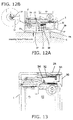
- FIG. 3 A state in which the injection needle 9 is exposed is shown in FIG. 3 , and in this state, the injection needle 9 is stuck into the skin 29 of the patient as shown in FIGS. 12A and 12B .
- the outer surface of the cover 25 is the skin contact face at the outer peripheral position of the injection needle mounting portion 2.
- the injection needle 9 can be pushed by the proper amount (the proper depth in this case) into the skin 29 as long as the cover 25 is pressed far enough to hit the skin 29.
- a stepped part 9a of the injection needle 9 is formed on the rear side of the injection needle 9 in the piercing direction, in a larger diameter than the injection needle 9.
- the distal end face of the stepped part 9a on the injection needle 9 side is substantially the same height as the front of the cover 25 (see FIG. 11 ). Accordingly, as long as the cover 25 is pressed against the skin 29, the injection needle 9 can be pushed the proper amount into the skin 29 (see FIGS. 12A and 12B ).
- the motor 8 is actuated, and the piston 5 is pushed to the pharmaceutical syringe mounting portion 3 side via the gear 7 and the piston feed screw 6. This allows the pharmaceutical inside the pharmaceutical syringe 4 to be injected into the patient via the injection needle 9.
- a cap 30 is removably mounted as shown in FIGS. 28 and 29 on the first end side (the piercing direction side) of the main body case 1. As shown in FIG. 5 , etc., the cap 30 is provided with an opening 31 that exposes the injection needle mounting portion 2.
- the cover 25 is disposed so as to be capable of opening and closing with respect to the opening 31.
- An opening and closing mechanism for opening and closing the cover 25 with respect to the opening 31 is provided inside the cap 30.
- the cap 30 is in the form of a cylinder having an upper face, and the above-mentioned opening 31, which is elliptical, is formed in this upper face (see FIGS. 5 , 25 , etc.).
- the cover 25 that covers the opening 31 in a state of being openable and closeable is in the form of an elliptical plate. As shown in FIG. 18 , two substantially L-shaped arms 32 formed from spring material are provided to the rear side of the cover 25 (the inner side of the cap 30).
- the substantially L-shaped arms 32 are disposed in parallel at a specific spacing along the opening and closing direction of the cover 25, and substantially L-shaped first ends are each fixed to the rear side of the cover 25.
- Slide pins 33 and 34 are provided substantially perpendicularly on the face in the middle portion of the substantially L-shaped arms 32 and the face on the second end side (the opposite side from the first end).
- the slide pins 34 are provided more to the main body case 1 side than the slide pins 33. As shown in FIG. 15 , the first end side of slide springs 35 is mounted to the slide pins 34. Meanwhile, the second end side of the slide springs 35 is mounted to engagement components (not shown) provided near the injection needle mounting portion 2 on the inside of the cap 30.
- the cover 25 is biased by the slide springs 35 in the closing direction.
- two slide grooves 36 and 37 are provided to the portions opposite the left and right slide pins 33 and 34 on the inner face side of the 30.
- the slide grooves 36 guide the slide pins 33 when the cover 25 is slid in the outer peripheral direction (outside direction) of the injection needle mounting portion 2.
- the slide grooves 37 guide the slide pins 34 when the cover 25 is slid in the outer peripheral direction (outside direction) of the injection needle mounting portion 2.
- the slide pins 33 and 34 are mounted in these slide grooves 36 and 37, the fact that the substantially L-shaped arms 32 are formed from spring material is taken advantage of, and the substantially L-shaped arms 32 are elastically deformed to the inside (the direction in which the two substantially L-shaped arms 32 approach each other). This allows the slide pins 33 and 34 to be engaged with the slide grooves 36 and 37 by elastic recovery after the slide pins 33 and 34 have been disposed on the inside of the slide grooves 36 and 37.
- the slide pins 33 and 34 are slid and guided along the slide grooves 36 and 37. Consequently, the cover 25 is opened and shut with respect to the opening 31. As a result, the injection needle mounting portion 2 can be exposed from the opening 31, or covered by the cover 25.
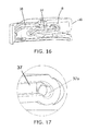
- the outer peripheral end side (the outer peripheral direction of the injection needle mounting portion 2) of the slide groove 37 is bent to the second end side (the power button 11 side) of the main body case 1, as shown in FIG. 17 .
- FIG. 17 is an enlarged view of the B portion in FIG. 16 (the circled portion, on the outer peripheral end side of the slide groove 37).
- the configuration shown in FIG. 17 is employed so that the cover 25 will not be opened accidentally in a state in which the opening 31 is not covered by the cover 25 (when it is open).
- the slide grooves 37 are provided with a bent part 37a at which the end on the side where the slide pins 34 move in a state of opening the cover 25 is bent to the second end side (the power button 11 side) of the main body case 1.
- the injection needle 9 is mounted to the injection needle mounting portion 2. After this, as shown in FIGS. 12A and 12B , the injection needle 9 is stuck into the skin 29 of the patient.
- the surface of the cover 25 becomes the skin contact face at the outer peripheral position of the injection needle mounting portion 2.
- the injection needle 9 can be pushed by the proper amount (the proper depth in this case) into the skin 29 as long as the cover 25 is pressed far enough to hit the skin 29.
- the distal end face on the injection needle 9 side of the stepped part 9a of the injection needle 9 is the same height as the front of the cover 25 (see FIG. 11 ). Accordingly, as long as the cover 25 is pressed against the skin 29, the injection needle 9 can be pushed the proper amount into the skin 29 (see FIGS. 12A and 12B ).
- the injection needle 9 is removed from the injection needle mounting portion 2 (also serves as the distal end side of the pharmaceutical syringe 4).
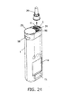
- the needle cover 28 is pushed into the injection needle 9, and then, as shown in FIG. 25 , the needle cover 28 rotates, and the needle unit 26 including the injection needle 9 is removed from the injection needle mounting portion 2 (also serves as the distal end side of the pharmaceutical syringe 4).
- the injection needle mounting portion 2 is covered by the cover 25, which is more sanitary.
- FIGS. 27 to 31 show the state when the cap 30 is removed from the main body case 1.
- the cap 30 can be removed from the main body case 1 as shown in FIGS. 27 to 31 .
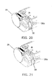
- a locking mechanism 38a rotates in conjunction with the operation of the lever 38 to release the lock, as shown in FIGS. 20 and 21 . More specifically, when the lever 38 is slid along the outer peripheral face of the cap 30, the locking mechanism 38a also rotates in conjunction with this, as shown in FIGS. 20 and 21 . In the state shown in FIG. 21 , because the lock by the locking mechanism 38a has been released, the cap 30 can be removed from the main body case 1.
- the locking mechanism should be used to ensure that the cap 30 and the main body case 1 are in a locked state.
- the cover 25, which covers the injection needle mounting portion 2 in an openable and closeable state while still attached to the main body case 1, is provided on the first end side of the main body case 1.
- the front of the cover 25 becomes the skin contact face at the outer peripheral position of the injection needle mounting portion 2 when the opening is open.
- the cover 25 is always attached to the main body case 1 regardless of whether the opening is open or closed. Consequently, unlike with a conventional cover in which the injection needle mounting portion is exposed by removing the cover from the main body case, the cover 25 will never be lost, which makes the pharmaceutical injection device more convenient to use.
- the cover 25 serves as the skin contact face at the outer peripheral position of the injection needle mounting portion 2, so the injection needle insertion depth during pharmaceutical injection can be stabilized. And since the operating orientation during pharmaceutical injection is also stable, the pharmaceutical injection device is more convenient to use in this respect as well.
- the pharmaceutical injection device pertaining to another embodiment of the present invention will now be described through reference to FIGS. 32A to 32C .
- the pharmaceutical injection device in this embodiment differs from the configuration in Embodiment 1 above in how the cover 25 is opened and closed.
- the configuration differs from that in Embodiment 1 in that an opening and closing mechanism is employed which opens and closes the cover 25 by sliding it parallel to the upper end face of the cap 30, along horizontal grooves 30a formed in the cap 30.
- the two horizontal grooves 30a are formed parallel to the upper end face of the cap 30, on mutually opposite faces of the inner peripheral face of the cylindrical cap 30.
- the cover 25 is attached to the upper end face of the cap 30 in a state in which it can be opened and closed with respect to the cap 30.
- the side face portions of the cover 25 can be slid along the two horizontal grooves 30a to open and close the cover, making it easy to switch between a state in which the injection needle mounting portion 2 is exposed and a state in which it is covered by the cover 25, without having to remove the cover 25 from the main body case 1.
- the pharmaceutical injection device pertaining to yet another embodiment of the present invention will now be described through reference to FIGS. 33A to 33C .
- the pharmaceutical injection device in this embodiment differs from the configuration in Embodiments 1 and 2 above in how the cover 25 is opened and closed.
- the configuration differs from that in Embodiments 1 and 2 in that an opening and closing mechanism is employed which opens and closes the cover 25 by horizontally turning it around a shaft 25a.
- the shaft 25a which is the turning center of the cover 25, is disposed along the lengthwise direction of the main body case 1.
- the cover 25 is attached to the upper end face of the cap 30 in a state in which it can be opened and closed with respect to the cap 30.
- FIGS. 33A to 33C it is easy to switch between a state in which the injection needle mounting portion 2 is exposed and a state in which it is covered by the cover 25, by turning the cover 25 horizontally to open and close it, without having to remove it from the main body case 1.
- the pharmaceutical injection device in this embodiment differs from the configuration in Embodiments 1 to 3 above in how the cover 25 is opened and closed.
- the configuration differs from that in Embodiments 1 to 3 in that an opening and closing mechanism is employed which switches the cover 25, in which an opening 25b is formed, between a state in which the injection needle mounting portion 2 is covered from the opening 25b (see FIG. 34A ) and a state in which it is exposed (see FIG. 34C ), by horizontally turning the cover 25 around the shaft 25a.
- the shaft 25a which is the horizontal turning center of the cover 25, is disposed along the lengthwise direction of the main body case 1, in the approximate center of the upper end face of the cap 30.
- the opening 25b formed in the cover 25 is formed large enough to expose the injection needle mounting portion 2 in a state in which the cover 25 has been horizontally turned and disposed over the injection needle mounting portion 2.
- the cover 25 is attached to the upper end face of the cap 30 in a state in which it can be opened and closed with respect to the cap 30.
- FIGS. 34A to 34C it is easy to switch between a state in which the injection needle mounting portion 2 is exposed and a state in which it is covered by the cover 25, by turning the cover 25 horizontally to open and close it, without having to remove it from the main body case 1.
- the pharmaceutical injection device pertaining to yet another embodiment of the present invention will now be described through reference to FIGS. 35A to 35C .
- the pharmaceutical injection device in this embodiment differs from the configuration in Embodiments 1 to 4 above in how the cover 25 is opened and closed.
- the configuration differs from that in Embodiments 1 to 4 in that an opening and closing mechanism is employed which opens and closes the cover by opening and closing a part of the cover 25 that covers above the injection needle mounting portion 2, via a hinge member 39.
- the hinge member 39 for opening and closing the cover 25 is disposed in the approximate center of the upper end face of the cap 30.
- the cover 25 is attached to the upper end face of the cap 30 in a state in which it can be opened and closed with respect to the cap 30.
- FIGS. 35A to 35C it is easy to switch between a state in which the injection needle mounting portion 2 is exposed and a state in which it is covered by the cover 25, by opening and closing the cover 25 via the hinge member 39, without having to remove it from the main body case 1.
- the pharmaceutical injection device pertaining to yet another embodiment of the present invention will now be described through reference to FIGS. 36A to 36C .
- the pharmaceutical injection device in this embodiment differs from the configuration in Embodiments 1 to 5 above in how the cover 25 is opened and closed.
- the members have basically the same function, shape, etc., so they will be numbered the same as in Embodiments 1 to 5, and will not be described in detail again.
- a stopper member 40 is disposed substantially in the horizontal direction, and at a height position that interferes with the L-shaped arms 32.
- the stopper member 40 here rotates around a rotational shape 40a and is thereby disposed (moved) at heights that interfere and do not interfere with the L-shaped arms 32. This rotation of the stopper member 40 happens in conjunction with the operation to open up the pharmaceutical syringe mounting portion 3.
- the cover is always mounted to the main body case, so it will not be lost, and the device can be used more conveniently, and therefore the present invention is expected to find wide application in the field of various kinds of pharmaceutical injection device, etc.
Landscapes
- Health & Medical Sciences (AREA)
- Vascular Medicine (AREA)
- Engineering & Computer Science (AREA)
- Anesthesiology (AREA)
- Biomedical Technology (AREA)
- Heart & Thoracic Surgery (AREA)
- Hematology (AREA)
- Life Sciences & Earth Sciences (AREA)
- Animal Behavior & Ethology (AREA)
- General Health & Medical Sciences (AREA)
- Public Health (AREA)
- Veterinary Medicine (AREA)
- Infusion, Injection, And Reservoir Apparatuses (AREA)
Abstract
Description
- The present invention relates to a pharmaceutical injection device for injecting a pharmaceutical into a human body, etc.
- A pharmaceutical injection device typically comprises a main body case having an injection needle mounting portion at a first end, a pharmaceutical syringe mounting portion provided inside the main body case, a piston provided movably with respect to a pharmaceutical syringe mounted to the pharmaceutical syringe mounting portion, and a drive mechanism for driving the piston.
- That is, with a conventional pharmaceutical injection device, first the pharmaceutical syringe is mounted to the pharmaceutical syringe mounting portion, and then the injection needle is mounted to the injection needle mounting portion. After this, the injection needle pierces the skin of the patient, and then a packing inside the pharmaceutical syringe is pushed by the piston under drive from the drive mechanism, which injects the pharmaceutical inside the pharmaceutical syringe through the injection needle and into the patient's body.
- Sometimes a cover that covers the injection needle mounting portion is removably mounted to the main body case in order to prevent soiling of the injection needle mounting portion (see
Patent Literature 1, for example). - Patent Literature 1: Japanese Unexamined Patent Application Publication (Translation of PCT Application) No.
2008-514249 - With the conventional example given above, the cover that covers the injection needle mounting portion is removably mounted to the main body case. This prevents the injection needle mounting portion from being soiled, but since the cover can be removed from the main body case, the cover may be lost, so this system can be inconvenient to use.
- In view of this, it is an object of the present invention to provide a pharmaceutical injection device that is more convenient to use.
- To achieve the stated object, the pharmaceutical injection device of the present invention comprises a main body case, a pharmaceutical syringe mounting portion, a piston, a drive mechanism, and a cover. The main body case has at a first end an injection needle mounting portion to which an injection needle is mounted. The pharmaceutical syringe mounting portion is provided inside the main body case, and a pharmaceutical syringe is mounted thereto. The piston is provided movably with respect to the pharmaceutical syringe that is mounted to the pharmaceutical syringe mounting portion. The drive mechanism drives the piston. The cover covers the pharmaceutical syringe mounting portion in an openable and closeable state so as to expose the injection needle mounting portion to the outside, while the cover is still attached to the first end side of the main body case.
- Consequently, the cover is provided on the first end side of the main body case in an openable and closeable state so as to cover the injection needle mounting portion. That is, since the cover is always mounted to the main body case, it will not be lost, making the device more convenient to use.
-
-
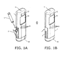
FIGS. 1A and 1B are oblique views of the pharmaceutical injection device pertaining to an embodiment of the present invention; -
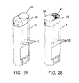
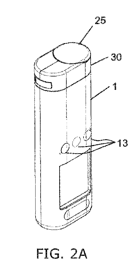
FIGS. 2A and 2B are oblique views of the pharmaceutical injection device in whichFIGS. 1A and 1B are flipped upside-down; -
FIG. 3 is a cross section of the pharmaceutical injection device inFIG. 1B ; -
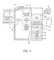
FIG. 4 is a control block diagram of the pharmaceutical injection device inFIG. 1B ; -
FIG. 5 is an oblique view of the usage state of the pharmaceutical injection device inFIG. 1B ; -
FIG. 6 is an oblique view of the usage state of the pharmaceutical injection device inFIG. 1B ; -
FIG. 7 is an oblique view of the usage state of the pharmaceutical injection device inFIG. 1B ; -
FIG. 8 is an oblique view of the usage state of the pharmaceutical injection device inFIG. 1B ; -
FIG. 9 is an oblique view of the usage state of the pharmaceutical injection device inFIG. 1B ; -
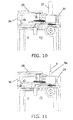
FIG. 10 is a detail cross section of the pharmaceutical injection device inFIG. 1B ; -
FIG. 11 is a detail cross section of the pharmaceutical injection device inFIG. 1B ; -
FIG. 12A is a detail cross section of the pharmaceutical injection device inFIGS. 1A and 1B , andFIG. 12B is an enlarged detail view of the A portion inFIG. 12A ; -
FIG. 13 is a detail cross section of the pharmaceutical injection device inFIG. 1A ; -
FIG. 14 is a detail cross section of the pharmaceutical injection device inFIG. 1A ; -
FIG. 15 is an oblique view of the pharmaceutical injection device inFIG. 1A ; -
FIG. 16 is a detail cross section of the pharmaceutical injection device inFIG. 1A ; -
FIG. 17 is an enlarged view of the B portion inFIG. 16 ; -
FIG. 18 is a detail oblique view of the pharmaceutical injection device inFIG. 1A ; -
FIG. 19 is a detail oblique view of the pharmaceutical injection device inFIG. 1A ; -
FIG. 20 is a detail oblique view of the pharmaceutical injection device inFIG. 1A ; -
FIG. 21 is a detail oblique view of the pharmaceutical injection device inFIG. 1A ; -
FIG. 22 is an oblique view of the usage state of the pharmaceutical injection device inFIG. 1A ; -
FIG. 23 is an oblique view of the usage state of the pharmaceutical injection device inFIG. 1A ; -
FIG. 24 is an oblique view of the usage state of the pharmaceutical injection device inFIG. 1A ; -
FIG. 25 is an oblique view of the usage state of the pharmaceutical injection device inFIG. 1A ; -
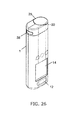
FIG. 26 is an oblique view of the usage state of the pharmaceutical injection device inFIG. 1A ; -
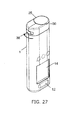
FIG. 27 is an oblique view of the usage state of the pharmaceutical injection device inFIG. 1A ; -
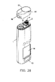
FIG. 28 is an oblique view of the usage state of the pharmaceutical injection device inFIG. 1A ; -
FIG. 29 is an oblique view of the usage state of the pharmaceutical injection device inFIG. 1A ; -
FIG. 30 is an oblique view of the usage state of the pharmaceutical injection device inFIG. 1A ; -
FIG. 31 is an oblique view of the usage state of the pharmaceutical injection device inFIG. 1A ; -
FIGS. 32A to 32C are oblique views of the configuration of the pharmaceutical injection device pertaining to another embodiment of the present invention; -
FIGS. 33A to 33C are oblique views of the configuration of the main components of the pharmaceutical injection device pertaining to yet another embodiment of the present invention; -
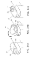
FIGS. 34A to 34C are oblique views of the configuration of the main components of the pharmaceutical injection device pertaining to yet another embodiment of the present invention; -
FIGS. 35A to 35C are oblique views of the configuration of the main components of the pharmaceutical injection device pertaining to yet another embodiment of the present invention; and -
FIGS. 36A to 36B are oblique views of the configuration of the main components of the pharmaceutical injection device pertaining to yet another embodiment of the present invention. - The pharmaceutical injection device pertaining to an embodiment of the present invention will now be described through reference to the appended drawings.
- As shown in
FIGS. 1A to 3 , the pharmaceutical injection device in this embodiment comprises a columnarmain body case 1, an injectionneedle mounting portion 2 provided on the first end side thereof (the piercing side), and a pharmaceuticalsyringe mounting portion 3 provided inside themain body case 1. - As shown in
FIGS. 1A and 1B , the pharmaceuticalsyringe mounting portion 3 can stick out from themain body case 1, and as shown inFIG. 1A , apharmaceutical syringe 4 is mounted to it in a state in which it has been pulled out from themain body case 1. After this, as shown inFIG. 1B , the pharmaceuticalsyringe mounting portion 3 is pushed into themain body case 1, so that thepharmaceutical syringe 4 is disposed at a specific position within themain body case 1 as shown inFIG. 3 . - In the state shown in
FIG. 3 , apiston 5 is disposed in a state of being movable with respect to thepharmaceutical syringe 4 mounted inside the pharmaceuticalsyringe mounting portion 3. - That is, a motor (drive mechanism) 8 is linked to the
piston 5 via a piston feed screw (drive mechanism) 6 and a gear (drive mechanism) 7. Therefore, when themotor 8 is actuated, thepiston 5 is pushed to the pharmaceuticalsyringe mounting portion 3 side via thegear 7 and thepiston feed screw 6. This allows the pharmaceutical inside thepharmaceutical syringe 4 to be injected into a patient's body, etc. (discussed in detail below). - The
pharmaceutical syringe 4 is usually in the form of a circular cylinder, and a gasket (not shown) that is pushed in by thepiston 5 is disposed in the interior on the rear end side (thepiston 5 side) in the piercing direction. - Also, a packing (not shown) at which the rear end side (the
piston 5 side) of aninjection needle 9 is pushed in is disposed on the distal end side (the first end side) of thepharmaceutical syringe 4. - In this embodiment, as shown in
FIGS. 2A to 3 , the distal end side (the opposite side from the piston 5) of thepharmaceutical syringe 4 becomes the injectionneedle mounting portion 2. When theinjection needle 9 is mounted to the injectionneedle mounting portion 2, the pharmaceutical in thepharmaceutical syringe 4 is injected through theinjection needle 9 into the body. - The
battery 10 shown inFIG. 3 is provided to supply power to the various components. - Furthermore, a
power button 11, apharmaceutical injection button 12, asetting button 13 for setting pharmaceutical injection quantities and so forth, and adisplay section 14 that displays the operating state and so forth are provided to the front of the main body case 1 (seeFIGS. 1A, 1B , andFIGS. 2A , 2B ). -
FIG. 4 shows the control blocks of this pharmaceutical injection device. - The
battery 10, thepower button 11, thepharmaceutical injection button 12, thesetting button 13, and thedisplay section 14 are connected to acontroller 15. - The
controller 15 is connected to themotor 8 via adrive circuit 16. Consequently, the amount of rotation of themotor 8, that is, the amount thepiston 5 is pushed in, is sensed by anencoder 17 and a pistonmovement distance sensor 18. - The rotational control of the
motor 8 is performed by amotor rotation controller 19, via thedrive circuit 16. Over-current in themotor 8 is detected by anover-current detection circuit 20. Thus, the drive of themotor 8 is quickly stopped when an abnormality due to over-current is detected. - A
central processing unit 21 and aROM 22 containing programs are provided inside thecontroller 15. Thecontroller 15 is also connected to amemory 23 that stores operational states, setting data, injection history, and so forth, and a sounder 24 that emits operating sounds, warning sounds, audio output, and so forth. - Now that the basic configuration of this embodiment has been understood from the above description, the main characteristics of this embodiment will be described.
- As shown in
FIGS. 2A and 2B , in this embodiment the injection needle mounting portion 2 (also serves as the distal end side of the pharmaceutical syringe 4) is provided on the first end side of themain body case 1. The injectionneedle mounting portion 2 is covered by acover 25 mounted to themain body case 1 in a state of being openable and closeable. - That is, when the
injection needle 9 is mounted, thecover 25 is opened (seeFIG. 2B ), and in this state, as shown inFIGS. 5 to 11 , theinjection needle 9 is mounted to the injectionneedle mounting portion 2. - First, as shown in
FIG. 5 , thecover 25 is opened, and then, as shown inFIG. 6 , aneedle unit 26 is threaded into the injection needle mounting portion 2 (also serves as the distal end side of the pharmaceutical syringe 4). - As shown in
FIGS. 5 to 11 , theneedle unit 26 is made up of theinjection needle 9, aneedle cap 27 that covers theinjection needle 9, and aneedle cover 28 on the outside of theneedle cap 27. Therefore, as shown inFIG. 6 , after theneedle unit 26 has been threaded into the injection needle mounting portion 2 (also serves as the distal end side of the pharmaceutical syringe 4), as shown inFIG. 7 , just theneedle cover 28 is pulled off. Next, as shown inFIG. 8 , theneedle cap 27 is pulled off as shown inFIG. 8 from the state inFIG. 10 . This exposes theinjection needle 9 as shown inFIGS. 9 and11 . - A state in which the
injection needle 9 is exposed is shown inFIG. 3 , and in this state, theinjection needle 9 is stuck into theskin 29 of the patient as shown inFIGS. 12A and 12B . - At this point, in this embodiment, the outer surface of the
cover 25 is the skin contact face at the outer peripheral position of the injectionneedle mounting portion 2. - That is, the
injection needle 9 can be pushed by the proper amount (the proper depth in this case) into theskin 29 as long as thecover 25 is pressed far enough to hit theskin 29. - A stepped
part 9a of theinjection needle 9 is formed on the rear side of theinjection needle 9 in the piercing direction, in a larger diameter than theinjection needle 9. The distal end face of the steppedpart 9a on theinjection needle 9 side is substantially the same height as the front of the cover 25 (seeFIG. 11 ). Accordingly, as long as thecover 25 is pressed against theskin 29, theinjection needle 9 can be pushed the proper amount into the skin 29 (seeFIGS. 12A and 12B ). - Therefore, if the
pharmaceutical injection button 12 is pressed in this state, themotor 8 is actuated, and thepiston 5 is pushed to the pharmaceuticalsyringe mounting portion 3 side via thegear 7 and thepiston feed screw 6. This allows the pharmaceutical inside thepharmaceutical syringe 4 to be injected into the patient via theinjection needle 9. - Next, the
cover 25, which can be opened and closed while still mounted to themain body case 1 so that the injectionneedle mounting portion 2 can be exposed to the outside, will be described in detail through reference toFIGS. 12A to 15 andFIGS. 28 and29 . - In this embodiment, a
cap 30 is removably mounted as shown inFIGS. 28 and29 on the first end side (the piercing direction side) of themain body case 1. As shown inFIG. 5 , etc., thecap 30 is provided with anopening 31 that exposes the injectionneedle mounting portion 2. - The
cover 25 is disposed so as to be capable of opening and closing with respect to theopening 31. An opening and closing mechanism for opening and closing thecover 25 with respect to theopening 31 is provided inside thecap 30. - That is, the
cap 30 is in the form of a cylinder having an upper face, and the above-mentionedopening 31, which is elliptical, is formed in this upper face (seeFIGS. 5 ,25 , etc.). - The
cover 25 that covers theopening 31 in a state of being openable and closeable is in the form of an elliptical plate. As shown inFIG. 18 , two substantially L-shapedarms 32 formed from spring material are provided to the rear side of the cover 25 (the inner side of the cap 30). - The substantially L-shaped
arms 32 are disposed in parallel at a specific spacing along the opening and closing direction of thecover 25, and substantially L-shaped first ends are each fixed to the rear side of thecover 25. - Slide pins 33 and 34 are provided substantially perpendicularly on the face in the middle portion of the substantially L-shaped
arms 32 and the face on the second end side (the opposite side from the first end). - Of these, the slide pins 34 are provided more to the
main body case 1 side than the slide pins 33. As shown inFIG. 15 , the first end side of slide springs 35 is mounted to the slide pins 34. Meanwhile, the second end side of the slide springs 35 is mounted to engagement components (not shown) provided near the injectionneedle mounting portion 2 on the inside of thecap 30. - With the configuration shown in
FIG. 15 , since two substantially L-shapedarms 32 are provided in parallel, two of the slide springs 35 are also provided in parallel. - That is, the
cover 25 is biased by the slide springs 35 in the closing direction. - As shown in
FIG. 16 , twoslide grooves - Of these, the
slide grooves 36 guide the slide pins 33 when thecover 25 is slid in the outer peripheral direction (outside direction) of the injectionneedle mounting portion 2. Theslide grooves 37 guide the slide pins 34 when thecover 25 is slid in the outer peripheral direction (outside direction) of the injectionneedle mounting portion 2. - When the slide pins 33 and 34 are mounted in these
slide grooves arms 32 are formed from spring material is taken advantage of, and the substantially L-shapedarms 32 are elastically deformed to the inside (the direction in which the two substantially L-shapedarms 32 approach each other). This allows the slide pins 33 and 34 to be engaged with theslide grooves slide grooves - That is, in this state, the slide pins 33 and 34 are slid and guided along the
slide grooves cover 25 is opened and shut with respect to theopening 31. As a result, the injectionneedle mounting portion 2 can be exposed from theopening 31, or covered by thecover 25. - In this embodiment, the outer peripheral end side (the outer peripheral direction of the injection needle mounting portion 2) of the
slide groove 37 is bent to the second end side (thepower button 11 side) of themain body case 1, as shown inFIG. 17 . -
FIG. 17 is an enlarged view of the B portion inFIG. 16 (the circled portion, on the outer peripheral end side of the slide groove 37). - That is, as discussed above, since the
cover 25 is biased in the closing direction by the slide springs 35, thecover 25 will not accidentally come open. - When the
cover 25 is pushed against the biasing force of the slide springs 35 (the operation to open the cover 25), theopening 31 is opened and the injectionneedle mounting portion 2 is exposed. The mounting of theinjection needle 9 is performed in this state, as discussed above, but in this case since thecover 25 is biased in the closing direction by the slide springs 35 as mentioned above, something has to be done to keep the cover from being accidentally closed. - In view of this, in this embodiment, the configuration shown in
FIG. 17 is employed so that thecover 25 will not be opened accidentally in a state in which theopening 31 is not covered by the cover 25 (when it is open). Specifically, theslide grooves 37 are provided with abent part 37a at which the end on the side where the slide pins 34 move in a state of opening thecover 25 is bent to the second end side (thepower button 11 side) of themain body case 1. - Consequently, the slide pins 34 are pulled against the
bent parts 37a on the outer peripheral end side of the slide grooves 37 (the outer peripheral direction of the injection needle mounting portion 2) by the slide springs 35. This prevents accidental closing even if thecover 25 is pulled in the closing direction by the slide springs 35. - As shown in
FIGS. 22 to 26 , if the outside of the cover 25 (the opposite side from the injection needle mounting portion 2) is lifted after the pharmaceutical is injected and theinjection needle 9 has been removed, the slide pins 34 will be lifted up from thebent parts 37a. As a result, the slide pins 34 are pulled by the slide springs 35, and thecover 25 can be closed from the state inFIG. 14 to that inFIG. 13 . - As shown in
FIGS. 5 to 12B , once thecover 25 is opened, as discussed above, theinjection needle 9 is mounted to the injectionneedle mounting portion 2. After this, as shown inFIGS. 12A and 12B , theinjection needle 9 is stuck into theskin 29 of the patient. - At this point, in this embodiment, as shown in
FIGS. 12A and 12B , the surface of thecover 25 becomes the skin contact face at the outer peripheral position of the injectionneedle mounting portion 2. - That is, the
injection needle 9 can be pushed by the proper amount (the proper depth in this case) into theskin 29 as long as thecover 25 is pressed far enough to hit theskin 29. - As discussed above, the distal end face on the
injection needle 9 side of the steppedpart 9a of theinjection needle 9 is the same height as the front of the cover 25 (seeFIG. 11 ). Accordingly, as long as thecover 25 is pressed against theskin 29, theinjection needle 9 can be pushed the proper amount into the skin 29 (seeFIGS. 12A and 12B ). - When the pharmaceutical is being injected in the state in
FIGS. 12A and 12B , thecover 25 has been pushed toward themain body case 1, so the slide pins 34 are pressed against thebent parts 37a on the outer peripheral end side (the outer peripheral direction of the injection needle mounting portion 2) of theslide grooves 37. Consequently, even if thecover 25 is pulled in the closing direction by the slide springs 35, thecover 25 can be prevented from accidentally closing. - Once this pharmaceutical injection is complete, as shown in
FIGS. 22 to 25 , theinjection needle 9 is removed from the injection needle mounting portion 2 (also serves as the distal end side of the pharmaceutical syringe 4). - At this point, the
needle cover 28 is pushed into theinjection needle 9, and then, as shown inFIG. 25 , theneedle cover 28 rotates, and theneedle unit 26 including theinjection needle 9 is removed from the injection needle mounting portion 2 (also serves as the distal end side of the pharmaceutical syringe 4). - In the state in
FIG. 25 , if the outside of the main body case 1 (the opposite side from the injection needle mounting portion 2) is lifted, the slide pins 34 are lifted up from the above-mentionedbent parts 37a. As a result, the slide pins 34 are pulled by the slide springs 35, and thecover 25 can be closed from its state inFIG. 25 to that inFIG. 26 . - In this state, the injection
needle mounting portion 2 is covered by thecover 25, which is more sanitary. -
FIGS. 27 to 31 show the state when thecap 30 is removed from themain body case 1. - That is, as shown in
FIG. 30 , when the injectionneedle mounting portion 2 is to be cleaned, or when thebattery 10 in themain body case 1 is to be replaced, thecap 30 can be removed from themain body case 1 as shown inFIGS. 27 to 31 . - In the removal of the
cap 30 from themain body case 1, when alever 38 provided to the outer peripheral face of thecap 30 is operated, alocking mechanism 38a rotates in conjunction with the operation of thelever 38 to release the lock, as shown inFIGS. 20 and 21 . More specifically, when thelever 38 is slid along the outer peripheral face of thecap 30, thelocking mechanism 38a also rotates in conjunction with this, as shown inFIGS. 20 and 21 . In the state shown inFIG. 21 , because the lock by thelocking mechanism 38a has been released, thecap 30 can be removed from themain body case 1. - Naturally, in the remounting of the
cap 30 to themain body case 1, the locking mechanism should be used to ensure that thecap 30 and themain body case 1 are in a locked state. - As discussed above, in this embodiment, the
cover 25, which covers the injectionneedle mounting portion 2 in an openable and closeable state while still attached to themain body case 1, is provided on the first end side of themain body case 1. - The front of the
cover 25 becomes the skin contact face at the outer peripheral position of the injectionneedle mounting portion 2 when the opening is open. - That is, the
cover 25 is always attached to themain body case 1 regardless of whether the opening is open or closed. Consequently, unlike with a conventional cover in which the injection needle mounting portion is exposed by removing the cover from the main body case, thecover 25 will never be lost, which makes the pharmaceutical injection device more convenient to use. - Also, during pharmaceutical injection, the
cover 25 serves as the skin contact face at the outer peripheral position of the injectionneedle mounting portion 2, so the injection needle insertion depth during pharmaceutical injection can be stabilized. And since the operating orientation during pharmaceutical injection is also stable, the pharmaceutical injection device is more convenient to use in this respect as well. - The pharmaceutical injection device pertaining to another embodiment of the present invention will now be described through reference to
FIGS. 32A to 32C . - The pharmaceutical injection device in this embodiment differs from the configuration in
Embodiment 1 above in how thecover 25 is opened and closed. - Other than this difference, the members have basically the same function, etc., so they will be numbered the same as in
Embodiment 1, and will not be described in detail again. - With the pharmaceutical injection device in this embodiment, as shown in
FIGS. 32A to 32C , the configuration differs from that inEmbodiment 1 in that an opening and closing mechanism is employed which opens and closes thecover 25 by sliding it parallel to the upper end face of thecap 30, alonghorizontal grooves 30a formed in thecap 30. - More specifically, as shown in
FIG. 32A and elsewhere, the twohorizontal grooves 30a are formed parallel to the upper end face of thecap 30, on mutually opposite faces of the inner peripheral face of thecylindrical cap 30. - Again in this embodiment, just as in
Embodiment 1 above, thecover 25 is attached to the upper end face of thecap 30 in a state in which it can be opened and closed with respect to thecap 30. - Consequently, as shown in
FIGS. 32A to 32C , the side face portions of thecover 25 can be slid along the twohorizontal grooves 30a to open and close the cover, making it easy to switch between a state in which the injectionneedle mounting portion 2 is exposed and a state in which it is covered by thecover 25, without having to remove thecover 25 from themain body case 1. - As a result, the same effect as in
Embodiment 1 above can be obtained. - The pharmaceutical injection device pertaining to yet another embodiment of the present invention will now be described through reference to
FIGS. 33A to 33C . - The pharmaceutical injection device in this embodiment differs from the configuration in
Embodiments cover 25 is opened and closed. - Other than this difference, the members have basically the same function, etc., so they will be numbered the same as in
Embodiments - Specifically, with the pharmaceutical injection device in this embodiment, as shown in
FIGS. 33A to 33C , the configuration differs from that inEmbodiments cover 25 by horizontally turning it around ashaft 25a. - More specifically, as shown in
FIG. 33A and elsewhere, theshaft 25a, which is the turning center of thecover 25, is disposed along the lengthwise direction of themain body case 1. - Again in this embodiment, just as in
Embodiment 1 above, thecover 25 is attached to the upper end face of thecap 30 in a state in which it can be opened and closed with respect to thecap 30. - Consequently, as shown in
FIGS. 33A to 33C , it is easy to switch between a state in which the injectionneedle mounting portion 2 is exposed and a state in which it is covered by thecover 25, by turning thecover 25 horizontally to open and close it, without having to remove it from themain body case 1. - As a result, the same effect as in
Embodiments - The pharmaceutical injection device pertaining to yet another embodiment of the present invention will now be described through reference to
FIGS. 34A to 34C . - The pharmaceutical injection device in this embodiment differs from the configuration in
Embodiments 1 to 3 above in how thecover 25 is opened and closed. - Other than this difference, the members have basically the same function, etc., so they will be numbered the same as in
Embodiments 1 to 3, and will not be described in detail again. - Specifically, with the pharmaceutical injection device in this embodiment, as shown in
FIGS. 34A to 34C , the configuration differs from that inEmbodiments 1 to 3 in that an opening and closing mechanism is employed which switches thecover 25, in which anopening 25b is formed, between a state in which the injectionneedle mounting portion 2 is covered from theopening 25b (seeFIG. 34A ) and a state in which it is exposed (seeFIG. 34C ), by horizontally turning thecover 25 around theshaft 25a. - More specifically, as shown in
FIG. 34A and elsewhere, theshaft 25a, which is the horizontal turning center of thecover 25, is disposed along the lengthwise direction of themain body case 1, in the approximate center of the upper end face of thecap 30. Also, theopening 25b formed in thecover 25 is formed large enough to expose the injectionneedle mounting portion 2 in a state in which thecover 25 has been horizontally turned and disposed over the injectionneedle mounting portion 2. - Again in this embodiment, just as in
Embodiment 1 above, thecover 25 is attached to the upper end face of thecap 30 in a state in which it can be opened and closed with respect to thecap 30. - Consequently, as shown in
FIGS. 34A to 34C , it is easy to switch between a state in which the injectionneedle mounting portion 2 is exposed and a state in which it is covered by thecover 25, by turning thecover 25 horizontally to open and close it, without having to remove it from themain body case 1. - As a result, the same effect as in
Embodiments 1 to 3 can be obtained. - The pharmaceutical injection device pertaining to yet another embodiment of the present invention will now be described through reference to
FIGS. 35A to 35C . - The pharmaceutical injection device in this embodiment differs from the configuration in
Embodiments 1 to 4 above in how thecover 25 is opened and closed. - Other than this difference, the members have basically the same function, etc., so they will be numbered the same as in
Embodiments 1 to 4, and will not be described in detail again. - Specifically, with the pharmaceutical injection device in this embodiment, as shown in
FIGS. 35A to 35C , the configuration differs from that inEmbodiments 1 to 4 in that an opening and closing mechanism is employed which opens and closes the cover by opening and closing a part of thecover 25 that covers above the injectionneedle mounting portion 2, via ahinge member 39. - More specifically, as shown in
FIG. 35A and elsewhere, thehinge member 39 for opening and closing thecover 25 is disposed in the approximate center of the upper end face of thecap 30. - Again in this embodiment, just as in
Embodiment 1 above, thecover 25 is attached to the upper end face of thecap 30 in a state in which it can be opened and closed with respect to thecap 30. - Consequently, as shown in
FIGS. 35A to 35C , it is easy to switch between a state in which the injectionneedle mounting portion 2 is exposed and a state in which it is covered by thecover 25, by opening and closing thecover 25 via thehinge member 39, without having to remove it from themain body case 1. - As a result, the same effect as in
Embodiments 1 to 4 can be obtained. - The pharmaceutical injection device pertaining to yet another embodiment of the present invention will now be described through reference to
FIGS. 36A to 36C . - The pharmaceutical injection device in this embodiment differs from the configuration in
Embodiments 1 to 5 above in how thecover 25 is opened and closed. - Other than this difference, the members have basically the same function, shape, etc., so they will be numbered the same as in
Embodiments 1 to 5, and will not be described in detail again. - Specifically, with the pharmaceutical injection device in this embodiment, as shown in
FIG. 36B , when the pharmaceuticalsyringe mounting portion 3 has been opened in order to replace thepharmaceutical syringe 4, astopper member 40 is disposed substantially in the horizontal direction, and at a height position that interferes with the L-shapedarms 32. - The
stopper member 40 here rotates around arotational shape 40a and is thereby disposed (moved) at heights that interfere and do not interfere with the L-shapedarms 32. This rotation of thestopper member 40 happens in conjunction with the operation to open up the pharmaceuticalsyringe mounting portion 3. - Consequently, movement of the L-shaped
arms 32 in the opening and closing direction of thecover 25 can be restricted by thestopper member 40 so that thecover 25 will not accidentally come open during replacement of thepharmaceutical syringe 4, etc. - Meanwhile, when the pharmaceutical
syringe mounting portion 3 is closed, as shown inFIG. 36A , thestopper member 40 is rotated downward and located lower than the L-shapedarms 32. - Consequently, movement of the L-shaped
arms 32 in the opening and closing direction of thecover 25 is not restricted by thestopper member 40, allowing thecover 25 to be opened with no problem. - This prevents the
cover 25 from accidentally coming open during pharmaceutical syringe replacement, so a pharmaceutical injection device can be obtained in which handling safety is further improved. - As discussed above, with the present invention, the cover is always mounted to the main body case, so it will not be lost, and the device can be used more conveniently, and therefore the present invention is expected to find wide application in the field of various kinds of pharmaceutical injection device, etc.
-
- 1 main body case
- 2 injection needle mounting portion
- 3 pharmaceutical syringe mounting portion
- 4 pharmaceutical syringe
- 5 piston
- 6 piston feed screw (drive mechanism)
- 7 gear (drive mechanism)
- 8 motor (drive mechanism)
- 9 injection needle
- 9a stepped part
- 10 battery
- 11 power button
- 12 pharmaceutical injection button
- 13 setting button
- 14 display section
- 15 controller
- 16 drive circuit
- 17 encoder
- 18 piston movement distance sensor
- 19 motor rotation controller
- 20 over-current detection circuit
- 21 central processing unit
- 22 ROM
- 23 memory
- 24 sounder
- 25 cover
- 25a shaft
- 25b opening
- 26 needle unit
- 27 needle cap
- 28 needle cover
- 29 skin
- 30 cap
- 30a horizontal groove
- 31 opening
- 32 L-shaped arm
- 33, 34 slide pin
- 35 slide spring
- 36, 37 slide groove
- 37a bent part
- 38 lever
- 38a locking mechanism
- 39 hinge member
- 40 stopper member
- 40a rotational shaft
Claims (9)
- A pharmaceutical injection device, comprising:a main body case having at a first end an injection needle mounting portion to which an injection needle is mounted;a pharmaceutical syringe mounting portion that is provided inside the main body case and to which a pharmaceutical syringe is mounted;a piston that is provided movably with respect to the pharmaceutical syringe mounted to the pharmaceutical syringe mounting portion;a drive mechanism configured to drive the piston; anda cover that covers the injection needle mounting portion in an openable and closeable state so as to expose the injection needle mounting portion to the outside, while the cover is still attached to the first end side of the main body case.
- The pharmaceutical injection device according to Claim 1,
further comprising an opening and closing mechanism for the cover, provided on the first end side of the main body case,
wherein the opening and closing mechanism has a slide pin provided to the cover, a slide groove configured to guide a sliding of the slide pin in an outer peripheral direction of the injection needle mounting portion, and a slide spring configured to bias the slide pin in a direction of closing the cover. - The pharmaceutical injection device according to Claim 2,
wherein the slide groove has a bent part that is bent to a second end side on the opposite side from the first end of the main body case, at an end on a side where the slide pin moves in a state of opening the cover. - The pharmaceutical injection device according to Claim 2 or 3,
wherein the opening and closing mechanism:has a first slide pin provided on the injection needle mounting portion side of the cover, and a second slide pin provided on an outer peripheral side of the injection needle mounting portion, as the slide pin,has a first slide groove that guides the sliding of the first slide pin in the outer peripheral direction of the injection needle mounting portion, and a second slide groove that guides the sliding of the second slide pin in the outer peripheral direction of the injection needle mounting portion, as the slide groove, andfurther has a slide spring that is linked to the second slide pin and is configured to bias in the direction of closing the cover. - The pharmaceutical injection device according to any of Claims 2 to 4,
further comprising a cap that is removably mounted on the first end side of the main body case,
wherein the cap has an opening that exposes the injection needle mounting portion, the cover is attached to the opening in a state of being openable and closeable, and the opening and closing mechanism is provided inside the cap. - The pharmaceutical injection device according to any of Claims 1 to 5,
wherein a surface of the cover is a face that comes into contact with the skin at an outer peripheral position of the injection needle mounting portion in a state of opening cover. - The pharmaceutical injection device according to Claim 1,
further comprising an opening and closing mechanism that has a shaft provided to the cover, and is configured to open and close the cover by turning the cover substantially horizontally around the shaft. - The pharmaceutical injection device according to Claim 1,
further comprising an opening and closing mechanism configured to open and close the cover via a hinge member provided to an end of the cover. - The pharmaceutical injection device according to any of Claims 1 to 8, further comprising:an opening and closing mechanism for the cover, provided on the first end side of the main body case; anda locking mechanism configured to restrict movement of the opening and closing mechanism so that the cover will not open in a state of opening the syringe mounting portion.
Applications Claiming Priority (2)
| Application Number | Priority Date | Filing Date | Title |
|---|---|---|---|
| JP2012133446 | 2012-06-13 | ||
| PCT/JP2013/003295 WO2013186997A1 (en) | 2012-06-13 | 2013-05-23 | Drug injection device |
Publications (3)
| Publication Number | Publication Date |
|---|---|
| EP2862588A1 true EP2862588A1 (en) | 2015-04-22 |
| EP2862588A4 EP2862588A4 (en) | 2015-07-29 |
| EP2862588B1 EP2862588B1 (en) | 2018-09-19 |
Family
ID=49757846
Family Applications (1)
| Application Number | Title | Priority Date | Filing Date |
|---|---|---|---|
| EP13804334.4A Active EP2862588B1 (en) | 2012-06-13 | 2013-05-23 | Drug injection device |
Country Status (4)
| Country | Link |
|---|---|
| US (2) | US10188797B2 (en) |
| EP (1) | EP2862588B1 (en) |
| JP (1) | JP6212486B2 (en) |
| WO (1) | WO2013186997A1 (en) |
Cited By (6)
| Publication number | Priority date | Publication date | Assignee | Title |
|---|---|---|---|---|
| WO2016196934A1 (en) * | 2015-06-04 | 2016-12-08 | Medimop Medical Projects Ltd. | Cartridge insertion for drug delivery device |
| US9861768B2 (en) | 2014-01-28 | 2018-01-09 | Panasonic Healthcare Holdings Co., Ltd. | Pharmaceutical injection device, and pharmaceutical management system |
| GB2578129A (en) * | 2018-10-17 | 2020-04-22 | My Invu Ltd | Injection apparatus |
| US11819666B2 (en) | 2017-05-30 | 2023-11-21 | West Pharma. Services IL, Ltd. | Modular drive train for wearable injector |
| US11857767B2 (en) | 2017-12-22 | 2024-01-02 | West Pharma. Services IL, Ltd. | Injector usable with different dimension cartridges |
| US12357767B2 (en) | 2016-08-01 | 2025-07-15 | West Pharma. Services IL, Ltd. | Partial door closure prevention spring |
Families Citing this family (32)
| Publication number | Priority date | Publication date | Assignee | Title |
|---|---|---|---|---|
| US10188797B2 (en) * | 2012-06-13 | 2019-01-29 | Phc Holdings Corporation | Pharmaceutical injection device |
| US10335550B2 (en) | 2014-04-25 | 2019-07-02 | Phc Holdings Corporation | Pharmaceutical injection device |
| AU2015372441A1 (en) | 2014-12-23 | 2017-08-10 | Automed Pty Ltd | Delivery apparatus, system and associated methods |
| WO2016145206A1 (en) | 2015-03-10 | 2016-09-15 | Regeneron Pharmaceuticals, Inc. | Aseptic piercing system and method |
| US10576207B2 (en) | 2015-10-09 | 2020-03-03 | West Pharma. Services IL, Ltd. | Angled syringe patch injector |
| US11311674B2 (en) | 2016-01-21 | 2022-04-26 | West Pharma. Services IL, Ltd. | Medicament delivery device comprising a visual indicator |
| US10603445B2 (en) * | 2016-06-09 | 2020-03-31 | Becton, Dickinson And Company | Needle actuator assembly for drug delivery system |
| USD805189S1 (en) | 2016-09-26 | 2017-12-12 | West Pharmaceutical Services, Inc. | Injector device |
| USD805187S1 (en) | 2016-09-26 | 2017-12-12 | West Pharmaceutical Services, Inc. | Injector device |
| USD804019S1 (en) | 2016-09-26 | 2017-11-28 | West Pharmaceutical Services, Inc. | Injector device |
| USD805188S1 (en) | 2016-09-26 | 2017-12-12 | West Pharmaceutical Services, Inc. | Injector device |
| USD804650S1 (en) | 2016-09-26 | 2017-12-05 | West Pharmaceutical Services, Inc. | Injector device |
| USD805186S1 (en) | 2016-09-26 | 2017-12-12 | West Pharmaceutical Services, Inc. | Injector device |
| USD805190S1 (en) | 2016-09-26 | 2017-12-12 | West Pharmaceutical Services, Inc. | Injector device |
| USD882765S1 (en) | 2016-10-26 | 2020-04-28 | West Pharmaceutical Services, Inc. | Injector device |
| USD805633S1 (en) | 2016-10-26 | 2017-12-19 | West Pharmaceutical Services, Inc. | Injector device |
| USD878556S1 (en) | 2016-10-26 | 2020-03-17 | West Pharmaceutical Services, Inc. | Injector device |
| USD807499S1 (en) | 2016-10-26 | 2018-01-09 | West Pharmaceutical Services, Inc. | Injector device |
| USD805632S1 (en) | 2016-10-26 | 2017-12-19 | West Pharmaceutical Services, Inc. | Injector device |
| USD878555S1 (en) | 2016-10-26 | 2020-03-17 | West Pharmaceutical Services, Inc. | Injector device |
| USD878557S1 (en) | 2016-10-26 | 2020-03-17 | West Pharmaceutical Services, Inc. | Injector device |
| USD808011S1 (en) | 2016-10-26 | 2018-01-16 | West Pharmaceutical Services, Inc. | Injector device |
| USD806234S1 (en) | 2016-10-26 | 2017-12-26 | West Pharmaceutical Services, Inc. | Injector device |
| USD806863S1 (en) | 2016-10-26 | 2018-01-02 | West Pharmaceutical Services, Inc. | Injector device |
| USD806235S1 (en) | 2016-10-26 | 2017-12-26 | West Pharmaceutical Services, Inc. | Injector device |
| EP3398630A1 (en) * | 2017-05-03 | 2018-11-07 | Sanofi-Aventis Deutschland GmbH | Auto-injector storage device |
| ES2919934T3 (en) | 2017-05-05 | 2022-07-29 | Regeneron Pharma | Autoinjector and related procedures for use |
| JP7009190B2 (en) * | 2017-12-06 | 2022-01-25 | Phcホールディングス株式会社 | Drug infusion system |
| US11957542B2 (en) | 2020-04-30 | 2024-04-16 | Automed Patent Holdco, Llc | Sensing complete injection for animal injection device |
| USD1007676S1 (en) | 2021-11-16 | 2023-12-12 | Regeneron Pharmaceuticals, Inc. | Wearable autoinjector |
| CN115400290B (en) * | 2022-09-01 | 2023-08-04 | 四川省医学科学院·四川省人民医院 | Insulin injection device |
| CN120459456A (en) * | 2025-07-04 | 2025-08-12 | 中国人民解放军空军军医大学 | A portable emergency drug storage and injection device |
Family Cites Families (21)
| Publication number | Priority date | Publication date | Assignee | Title |
|---|---|---|---|---|
| UA42066C2 (en) | 1995-06-02 | 2001-10-15 | Ново Нордіск А/С | Syringe for metered injections of drug |
| US6186982B1 (en) * | 1998-05-05 | 2001-02-13 | Elan Corporation, Plc | Subcutaneous drug delivery device with improved filling system |
| IE970782A1 (en) * | 1997-10-22 | 1999-05-05 | Elan Corp | An improved automatic syringe |
| US6334857B1 (en) * | 1999-01-11 | 2002-01-01 | Sims Portex Inc. | Needle protection apparatus used with a vial |
| US6547764B2 (en) * | 2000-05-31 | 2003-04-15 | Novo Nordisk A/S | Double pointed injection needle |
| JPWO2003057286A1 (en) | 2001-12-13 | 2005-05-12 | 松下電器産業株式会社 | Medical dosing device |
| JP4448448B2 (en) | 2002-09-24 | 2010-04-07 | エス・ホー・エル・グループ・アクチボラゲット | Injection device |
| US20040116863A1 (en) * | 2002-12-12 | 2004-06-17 | Chang-Ming Yang | Intra-venous catheter structure |
| CA2767916C (en) * | 2004-02-18 | 2014-04-15 | Ares Trading S.A. | Hand-held electronically controlled injection device for injecting liquid medications |
| JP4549079B2 (en) * | 2004-03-05 | 2010-09-22 | パナソニック株式会社 | Medical dosing device |
| EP1640029A1 (en) | 2004-09-24 | 2006-03-29 | Novo Nordisk A/S | Injection device with cap |
| US7186958B1 (en) * | 2005-09-01 | 2007-03-06 | Zhao Wei, Llc | Inhaler |
| JP4216842B2 (en) * | 2005-10-21 | 2009-01-28 | さよ子 森川 | Injection needle attachment / detachment jig |
| PL2337597T3 (en) | 2008-09-18 | 2019-10-31 | Becton Dickinson Co | Medical injector with coupled body portions |
| US8556862B2 (en) | 2008-09-18 | 2013-10-15 | Becton Dickinson And Company | Needle mounting feature for ensuring proper reconstitution sequence |
| DE202009001836U1 (en) * | 2009-02-13 | 2009-05-20 | Dieter Hölzle Technik-Projekte GmbH | Electromechanical injection device |
| US8157769B2 (en) * | 2009-09-15 | 2012-04-17 | Medimop Medical Projects Ltd. | Cartridge insertion assembly for drug delivery system |
| EP2364739A1 (en) | 2010-03-09 | 2011-09-14 | Sanofi-Aventis Deutschland GmbH | Re-usable autoinjector |
| CN103328026B (en) | 2010-07-02 | 2015-05-13 | 卡勒贝控股有限公司,公司编号:681498 | Preservative-free follicle stimulating hormone solution delivery device |
| RU2572738C2 (en) * | 2010-07-02 | 2016-01-20 | Санофи-Авентис Дойчланд Гмбх | Safety device for prefilled syringe and injection device |
| US10188797B2 (en) * | 2012-06-13 | 2019-01-29 | Phc Holdings Corporation | Pharmaceutical injection device |
-
2013
- 2013-05-23 US US14/404,013 patent/US10188797B2/en active Active
- 2013-05-23 JP JP2014520892A patent/JP6212486B2/en active Active
- 2013-05-23 WO PCT/JP2013/003295 patent/WO2013186997A1/en not_active Ceased
- 2013-05-23 EP EP13804334.4A patent/EP2862588B1/en active Active
-
2018
- 2018-11-20 US US16/196,555 patent/US10967127B2/en active Active
Cited By (11)
| Publication number | Priority date | Publication date | Assignee | Title |
|---|---|---|---|---|
| US9861768B2 (en) | 2014-01-28 | 2018-01-09 | Panasonic Healthcare Holdings Co., Ltd. | Pharmaceutical injection device, and pharmaceutical management system |
| WO2016196934A1 (en) * | 2015-06-04 | 2016-12-08 | Medimop Medical Projects Ltd. | Cartridge insertion for drug delivery device |
| CN107683158A (en) * | 2015-06-04 | 2018-02-09 | 麦迪麦珀医疗工程有限公司 | Cartridge insertion for drug release devices |
| US11207465B2 (en) | 2015-06-04 | 2021-12-28 | West Pharma. Services Il. Ltd. | Cartridge insertion for drug delivery device |
| EP4252798A3 (en) * | 2015-06-04 | 2023-10-25 | Medimop Medical Projects Ltd. | Cartridge insertion for drug delivery device |
| US11931552B2 (en) | 2015-06-04 | 2024-03-19 | West Pharma Services Il, Ltd. | Cartridge insertion for drug delivery device |
| US12357767B2 (en) | 2016-08-01 | 2025-07-15 | West Pharma. Services IL, Ltd. | Partial door closure prevention spring |
| US11819666B2 (en) | 2017-05-30 | 2023-11-21 | West Pharma. Services IL, Ltd. | Modular drive train for wearable injector |
| US11857767B2 (en) | 2017-12-22 | 2024-01-02 | West Pharma. Services IL, Ltd. | Injector usable with different dimension cartridges |
| GB2578129A (en) * | 2018-10-17 | 2020-04-22 | My Invu Ltd | Injection apparatus |
| WO2020079104A1 (en) * | 2018-10-17 | 2020-04-23 | My Invu Limited | Injection apparatus |
Also Published As
| Publication number | Publication date |
|---|---|
| US10188797B2 (en) | 2019-01-29 |
| US10967127B2 (en) | 2021-04-06 |
| EP2862588A4 (en) | 2015-07-29 |
| US20150165121A1 (en) | 2015-06-18 |
| JP6212486B2 (en) | 2017-10-11 |
| JPWO2013186997A1 (en) | 2016-02-04 |
| US20190083707A1 (en) | 2019-03-21 |
| EP2862588B1 (en) | 2018-09-19 |
| WO2013186997A1 (en) | 2013-12-19 |
Similar Documents
| Publication | Publication Date | Title |
|---|---|---|
| US10967127B2 (en) | Pharmaceutical injection device | |
| JP6979119B2 (en) | Delayed cartridge perforation mechanism for syringes | |
| JP7137004B2 (en) | Auto-injector with efficient insertion system | |
| JP6254714B2 (en) | Drug cartridge holding unit and drug injection device including the same | |
| EP3498323B1 (en) | Autoinjector apparatus | |
| EP3178505B1 (en) | Medicament injection device | |
| JP5437343B2 (en) | Hand-held electronically controlled injection machine for liquid drug injection | |
| JP5917854B2 (en) | Pen injection device needle supply and storage device | |
| EP3202445B1 (en) | Pharmaceutical syringe unit, pharmaceutical injection device equipped with said unit, injection needle attachment and removal fixture, and storage case | |
| EP2945664B1 (en) | Lock for drug injection device | |
| KR20030093285A (en) | Improvements in and relating to an injection device | |
| US7785338B2 (en) | Lancing aid comprising a lancet system that is protected against re-use | |
| CN111246902B (en) | Premature activation prevention mechanism for syringe | |
| CN104284689A (en) | Injection device | |
| KR20210143830A (en) | Activation Mechanisms for On-Body Drug Delivery Devices | |
| CN117881442A (en) | Automatic injection device and cassette system with a cap removal mechanism | |
| CN111194228A (en) | Syringe energizing mechanism | |
| JP6819234B2 (en) | Lancet | |
| RU2781570C1 (en) | Autoinjector with a needle casing | |
| KR101548458B1 (en) | Syringe type device for injecting medical fluid | |
| CN117881441A (en) | Box with syringe holder cover |
Legal Events
| Date | Code | Title | Description |
|---|---|---|---|
| PUAI | Public reference made under article 153(3) epc to a published international application that has entered the european phase |
Free format text: ORIGINAL CODE: 0009012 |
|
| 17P | Request for examination filed |
Effective date: 20150113 |
|
| AK | Designated contracting states |
Kind code of ref document: A1 Designated state(s): AL AT BE BG CH CY CZ DE DK EE ES FI FR GB GR HR HU IE IS IT LI LT LU LV MC MK MT NL NO PL PT RO RS SE SI SK SM TR |
|
| AX | Request for extension of the european patent |
Extension state: BA ME |
|
| RA4 | Supplementary search report drawn up and despatched (corrected) |
Effective date: 20150701 |
|
| RIC1 | Information provided on ipc code assigned before grant |
Ipc: A61M 5/20 20060101ALI20150625BHEP Ipc: A61M 5/315 20060101ALI20150625BHEP Ipc: A61M 5/31 20060101AFI20150625BHEP Ipc: A61M 5/24 20060101ALI20150625BHEP |
|
| DAX | Request for extension of the european patent (deleted) | ||
| RIC1 | Information provided on ipc code assigned before grant |
Ipc: A61M 5/315 20060101ALI20180214BHEP Ipc: A61M 5/20 20060101ALI20180214BHEP Ipc: A61M 5/31 20060101AFI20180214BHEP Ipc: A61M 5/24 20060101ALI20180214BHEP |
|
| GRAP | Despatch of communication of intention to grant a patent |
Free format text: ORIGINAL CODE: EPIDOSNIGR1 |
|
| STAA | Information on the status of an ep patent application or granted ep patent |
Free format text: STATUS: GRANT OF PATENT IS INTENDED |
|
| INTG | Intention to grant announced |
Effective date: 20180403 |
|
| RAP1 | Party data changed (applicant data changed or rights of an application transferred) |
Owner name: PHC HOLDINGS CORPORATION |
|
| GRAS | Grant fee paid |
Free format text: ORIGINAL CODE: EPIDOSNIGR3 |
|
| GRAA | (expected) grant |
Free format text: ORIGINAL CODE: 0009210 |
|
| STAA | Information on the status of an ep patent application or granted ep patent |
Free format text: STATUS: THE PATENT HAS BEEN GRANTED |
|
| AK | Designated contracting states |
Kind code of ref document: B1 Designated state(s): AL AT BE BG CH CY CZ DE DK EE ES FI FR GB GR HR HU IE IS IT LI LT LU LV MC MK MT NL NO PL PT RO RS SE SI SK SM TR |
|
| REG | Reference to a national code |
Ref country code: GB Ref legal event code: FG4D |
|
| REG | Reference to a national code |
Ref country code: CH Ref legal event code: EP |
|
| REG | Reference to a national code |
Ref country code: AT Ref legal event code: REF Ref document number: 1042519 Country of ref document: AT Kind code of ref document: T Effective date: 20181015 |
|
| REG | Reference to a national code |
Ref country code: IE Ref legal event code: FG4D |
|
| REG | Reference to a national code |
Ref country code: DE Ref legal event code: R096 Ref document number: 602013043964 Country of ref document: DE |
|
| REG | Reference to a national code |
Ref country code: NL Ref legal event code: MP Effective date: 20180919 |
|
| PG25 | Lapsed in a contracting state [announced via postgrant information from national office to epo] |
Ref country code: SE Free format text: LAPSE BECAUSE OF FAILURE TO SUBMIT A TRANSLATION OF THE DESCRIPTION OR TO PAY THE FEE WITHIN THE PRESCRIBED TIME-LIMIT Effective date: 20180919 Ref country code: BG Free format text: LAPSE BECAUSE OF FAILURE TO SUBMIT A TRANSLATION OF THE DESCRIPTION OR TO PAY THE FEE WITHIN THE PRESCRIBED TIME-LIMIT Effective date: 20181219 Ref country code: RS Free format text: LAPSE BECAUSE OF FAILURE TO SUBMIT A TRANSLATION OF THE DESCRIPTION OR TO PAY THE FEE WITHIN THE PRESCRIBED TIME-LIMIT Effective date: 20180919 Ref country code: LT Free format text: LAPSE BECAUSE OF FAILURE TO SUBMIT A TRANSLATION OF THE DESCRIPTION OR TO PAY THE FEE WITHIN THE PRESCRIBED TIME-LIMIT Effective date: 20180919 Ref country code: NO Free format text: LAPSE BECAUSE OF FAILURE TO SUBMIT A TRANSLATION OF THE DESCRIPTION OR TO PAY THE FEE WITHIN THE PRESCRIBED TIME-LIMIT Effective date: 20181219 Ref country code: FI Free format text: LAPSE BECAUSE OF FAILURE TO SUBMIT A TRANSLATION OF THE DESCRIPTION OR TO PAY THE FEE WITHIN THE PRESCRIBED TIME-LIMIT Effective date: 20180919 Ref country code: GR Free format text: LAPSE BECAUSE OF FAILURE TO SUBMIT A TRANSLATION OF THE DESCRIPTION OR TO PAY THE FEE WITHIN THE PRESCRIBED TIME-LIMIT Effective date: 20181220 |
|
| REG | Reference to a national code |
Ref country code: LT Ref legal event code: MG4D |
|
| PG25 | Lapsed in a contracting state [announced via postgrant information from national office to epo] |
Ref country code: LV Free format text: LAPSE BECAUSE OF FAILURE TO SUBMIT A TRANSLATION OF THE DESCRIPTION OR TO PAY THE FEE WITHIN THE PRESCRIBED TIME-LIMIT Effective date: 20180919 Ref country code: HR Free format text: LAPSE BECAUSE OF FAILURE TO SUBMIT A TRANSLATION OF THE DESCRIPTION OR TO PAY THE FEE WITHIN THE PRESCRIBED TIME-LIMIT Effective date: 20180919 Ref country code: AL Free format text: LAPSE BECAUSE OF FAILURE TO SUBMIT A TRANSLATION OF THE DESCRIPTION OR TO PAY THE FEE WITHIN THE PRESCRIBED TIME-LIMIT Effective date: 20180919 |
|
| REG | Reference to a national code |
Ref country code: AT Ref legal event code: MK05 Ref document number: 1042519 Country of ref document: AT Kind code of ref document: T Effective date: 20180919 |
|
| PG25 | Lapsed in a contracting state [announced via postgrant information from national office to epo] |
Ref country code: IT Free format text: LAPSE BECAUSE OF FAILURE TO SUBMIT A TRANSLATION OF THE DESCRIPTION OR TO PAY THE FEE WITHIN THE PRESCRIBED TIME-LIMIT Effective date: 20180919 Ref country code: RO Free format text: LAPSE BECAUSE OF FAILURE TO SUBMIT A TRANSLATION OF THE DESCRIPTION OR TO PAY THE FEE WITHIN THE PRESCRIBED TIME-LIMIT Effective date: 20180919 Ref country code: PL Free format text: LAPSE BECAUSE OF FAILURE TO SUBMIT A TRANSLATION OF THE DESCRIPTION OR TO PAY THE FEE WITHIN THE PRESCRIBED TIME-LIMIT Effective date: 20180919 Ref country code: IS Free format text: LAPSE BECAUSE OF FAILURE TO SUBMIT A TRANSLATION OF THE DESCRIPTION OR TO PAY THE FEE WITHIN THE PRESCRIBED TIME-LIMIT Effective date: 20190119 Ref country code: ES Free format text: LAPSE BECAUSE OF FAILURE TO SUBMIT A TRANSLATION OF THE DESCRIPTION OR TO PAY THE FEE WITHIN THE PRESCRIBED TIME-LIMIT Effective date: 20180919 Ref country code: EE Free format text: LAPSE BECAUSE OF FAILURE TO SUBMIT A TRANSLATION OF THE DESCRIPTION OR TO PAY THE FEE WITHIN THE PRESCRIBED TIME-LIMIT Effective date: 20180919 Ref country code: CZ Free format text: LAPSE BECAUSE OF FAILURE TO SUBMIT A TRANSLATION OF THE DESCRIPTION OR TO PAY THE FEE WITHIN THE PRESCRIBED TIME-LIMIT Effective date: 20180919 Ref country code: NL Free format text: LAPSE BECAUSE OF FAILURE TO SUBMIT A TRANSLATION OF THE DESCRIPTION OR TO PAY THE FEE WITHIN THE PRESCRIBED TIME-LIMIT Effective date: 20180919 Ref country code: AT Free format text: LAPSE BECAUSE OF FAILURE TO SUBMIT A TRANSLATION OF THE DESCRIPTION OR TO PAY THE FEE WITHIN THE PRESCRIBED TIME-LIMIT Effective date: 20180919 |
|
| PG25 | Lapsed in a contracting state [announced via postgrant information from national office to epo] |
Ref country code: SM Free format text: LAPSE BECAUSE OF FAILURE TO SUBMIT A TRANSLATION OF THE DESCRIPTION OR TO PAY THE FEE WITHIN THE PRESCRIBED TIME-LIMIT Effective date: 20180919 Ref country code: SK Free format text: LAPSE BECAUSE OF FAILURE TO SUBMIT A TRANSLATION OF THE DESCRIPTION OR TO PAY THE FEE WITHIN THE PRESCRIBED TIME-LIMIT Effective date: 20180919 Ref country code: PT Free format text: LAPSE BECAUSE OF FAILURE TO SUBMIT A TRANSLATION OF THE DESCRIPTION OR TO PAY THE FEE WITHIN THE PRESCRIBED TIME-LIMIT Effective date: 20190119 |
|
| REG | Reference to a national code |
Ref country code: DE Ref legal event code: R097 Ref document number: 602013043964 Country of ref document: DE |
|
| PLBE | No opposition filed within time limit |
Free format text: ORIGINAL CODE: 0009261 |
|
| STAA | Information on the status of an ep patent application or granted ep patent |
Free format text: STATUS: NO OPPOSITION FILED WITHIN TIME LIMIT |
|
| PG25 | Lapsed in a contracting state [announced via postgrant information from national office to epo] |
Ref country code: DK Free format text: LAPSE BECAUSE OF FAILURE TO SUBMIT A TRANSLATION OF THE DESCRIPTION OR TO PAY THE FEE WITHIN THE PRESCRIBED TIME-LIMIT Effective date: 20180919 |
|
| 26N | No opposition filed |
Effective date: 20190620 |
|
| PG25 | Lapsed in a contracting state [announced via postgrant information from national office to epo] |
Ref country code: SI Free format text: LAPSE BECAUSE OF FAILURE TO SUBMIT A TRANSLATION OF THE DESCRIPTION OR TO PAY THE FEE WITHIN THE PRESCRIBED TIME-LIMIT Effective date: 20180919 |
|
| REG | Reference to a national code |
Ref country code: CH Ref legal event code: PL |
|
| PG25 | Lapsed in a contracting state [announced via postgrant information from national office to epo] |
Ref country code: MC Free format text: LAPSE BECAUSE OF FAILURE TO SUBMIT A TRANSLATION OF THE DESCRIPTION OR TO PAY THE FEE WITHIN THE PRESCRIBED TIME-LIMIT Effective date: 20180919 Ref country code: CH Free format text: LAPSE BECAUSE OF NON-PAYMENT OF DUE FEES Effective date: 20190531 Ref country code: LI Free format text: LAPSE BECAUSE OF NON-PAYMENT OF DUE FEES Effective date: 20190531 |
|
| REG | Reference to a national code |
Ref country code: BE Ref legal event code: MM Effective date: 20190531 |
|
| PG25 | Lapsed in a contracting state [announced via postgrant information from national office to epo] |
Ref country code: LU Free format text: LAPSE BECAUSE OF NON-PAYMENT OF DUE FEES Effective date: 20190523 |
|
| PG25 | Lapsed in a contracting state [announced via postgrant information from national office to epo] |
Ref country code: TR Free format text: LAPSE BECAUSE OF FAILURE TO SUBMIT A TRANSLATION OF THE DESCRIPTION OR TO PAY THE FEE WITHIN THE PRESCRIBED TIME-LIMIT Effective date: 20180919 |
|
| PG25 | Lapsed in a contracting state [announced via postgrant information from national office to epo] |
Ref country code: IE Free format text: LAPSE BECAUSE OF NON-PAYMENT OF DUE FEES Effective date: 20190523 |
|
| PG25 | Lapsed in a contracting state [announced via postgrant information from national office to epo] |
Ref country code: BE Free format text: LAPSE BECAUSE OF NON-PAYMENT OF DUE FEES Effective date: 20190531 |
|
| PG25 | Lapsed in a contracting state [announced via postgrant information from national office to epo] |
Ref country code: FR Free format text: LAPSE BECAUSE OF NON-PAYMENT OF DUE FEES Effective date: 20190531 |
|
| PG25 | Lapsed in a contracting state [announced via postgrant information from national office to epo] |
Ref country code: CY Free format text: LAPSE BECAUSE OF FAILURE TO SUBMIT A TRANSLATION OF THE DESCRIPTION OR TO PAY THE FEE WITHIN THE PRESCRIBED TIME-LIMIT Effective date: 20180919 |
|
| PG25 | Lapsed in a contracting state [announced via postgrant information from national office to epo] |
Ref country code: HU Free format text: LAPSE BECAUSE OF FAILURE TO SUBMIT A TRANSLATION OF THE DESCRIPTION OR TO PAY THE FEE WITHIN THE PRESCRIBED TIME-LIMIT; INVALID AB INITIO Effective date: 20130523 Ref country code: MT Free format text: LAPSE BECAUSE OF FAILURE TO SUBMIT A TRANSLATION OF THE DESCRIPTION OR TO PAY THE FEE WITHIN THE PRESCRIBED TIME-LIMIT Effective date: 20180919 |
|
| PG25 | Lapsed in a contracting state [announced via postgrant information from national office to epo] |
Ref country code: MK Free format text: LAPSE BECAUSE OF FAILURE TO SUBMIT A TRANSLATION OF THE DESCRIPTION OR TO PAY THE FEE WITHIN THE PRESCRIBED TIME-LIMIT Effective date: 20180919 |
|
| PGFP | Annual fee paid to national office [announced via postgrant information from national office to epo] |
Ref country code: DE Payment date: 20250529 Year of fee payment: 13 |
|
| PGFP | Annual fee paid to national office [announced via postgrant information from national office to epo] |
Ref country code: GB Payment date: 20250527 Year of fee payment: 13 |