EP2862396B1 - Method and apparatus for dynamically configuring a cell update message - Google Patents
Method and apparatus for dynamically configuring a cell update message Download PDFInfo
- Publication number
- EP2862396B1 EP2862396B1 EP13742792.8A EP13742792A EP2862396B1 EP 2862396 B1 EP2862396 B1 EP 2862396B1 EP 13742792 A EP13742792 A EP 13742792A EP 2862396 B1 EP2862396 B1 EP 2862396B1
- Authority
- EP
- European Patent Office
- Prior art keywords
- update message
- cell update
- support
- cell
- drx
- Prior art date
- Legal status (The legal status is an assumption and is not a legal conclusion. Google has not performed a legal analysis and makes no representation as to the accuracy of the status listed.)
- Active
Links
- 238000000034 method Methods 0.000 title claims description 38
- 230000004044 response Effects 0.000 claims description 9
- 238000004590 computer program Methods 0.000 claims description 6
- 238000004891 communication Methods 0.000 description 32
- 238000012545 processing Methods 0.000 description 15
- 230000006870 function Effects 0.000 description 14
- 238000010586 diagram Methods 0.000 description 12
- 230000005540 biological transmission Effects 0.000 description 11
- 238000005516 engineering process Methods 0.000 description 8
- 230000011664 signaling Effects 0.000 description 5
- 230000001960 triggered effect Effects 0.000 description 5
- 238000013461 design Methods 0.000 description 4
- 238000001228 spectrum Methods 0.000 description 3
- 230000001413 cellular effect Effects 0.000 description 2
- 239000003795 chemical substances by application Substances 0.000 description 2
- 230000006835 compression Effects 0.000 description 2
- 238000007906 compression Methods 0.000 description 2
- 238000005259 measurement Methods 0.000 description 2
- 230000007246 mechanism Effects 0.000 description 2
- 238000010295 mobile communication Methods 0.000 description 2
- 238000012986 modification Methods 0.000 description 2
- 230000004048 modification Effects 0.000 description 2
- 230000003287 optical effect Effects 0.000 description 2
- 230000008520 organization Effects 0.000 description 2
- 230000008569 process Effects 0.000 description 2
- 238000012546 transfer Methods 0.000 description 2
- 230000007704 transition Effects 0.000 description 2
- 101000741965 Homo sapiens Inactive tyrosine-protein kinase PRAG1 Proteins 0.000 description 1
- 102100038659 Inactive tyrosine-protein kinase PRAG1 Human genes 0.000 description 1
- 230000003044 adaptive effect Effects 0.000 description 1
- 238000013459 approach Methods 0.000 description 1
- 238000003491 array Methods 0.000 description 1
- 238000013475 authorization Methods 0.000 description 1
- 230000008859 change Effects 0.000 description 1
- 238000005562 fading Methods 0.000 description 1
- 230000002349 favourable effect Effects 0.000 description 1
- 230000008713 feedback mechanism Effects 0.000 description 1
- 230000003116 impacting effect Effects 0.000 description 1
- 230000000977 initiatory effect Effects 0.000 description 1
- 239000005022 packaging material Substances 0.000 description 1
- 230000002093 peripheral effect Effects 0.000 description 1
- 230000011218 segmentation Effects 0.000 description 1
Images


Classifications
-
- H—ELECTRICITY
- H04—ELECTRIC COMMUNICATION TECHNIQUE
- H04W—WIRELESS COMMUNICATION NETWORKS
- H04W60/00—Affiliation to network, e.g. registration; Terminating affiliation with the network, e.g. de-registration
- H04W60/02—Affiliation to network, e.g. registration; Terminating affiliation with the network, e.g. de-registration by periodical registration
-
- H—ELECTRICITY
- H04—ELECTRIC COMMUNICATION TECHNIQUE
- H04W—WIRELESS COMMUNICATION NETWORKS
- H04W28/00—Network traffic management; Network resource management
- H04W28/02—Traffic management, e.g. flow control or congestion control
- H04W28/06—Optimizing the usage of the radio link, e.g. header compression, information sizing, discarding information
Definitions
- aspects of the present disclosure relate generally to wireless communication systems, and more particularly, to configuration of cell update message.
- Wireless communication networks are widely deployed to provide various communication services such as telephony, video, data, messaging, broadcasts, and so on.
- Such networks which are usually multiple access networks, support communications for multiple users by sharing the available network resources.
- UTRAN UMTS Terrestrial Radio Access Network
- the UTRAN is the radio access network (RAN) defined as a part of the Universal Mobile Telecommunications System (UMTS), a third generation (3G) mobile phone technology supported by the 3rd Generation Partnership Project (3GPP).
- UMTS Universal Mobile Telecommunications System
- 3GPP 3rd Generation Partnership Project
- the UMTS which is the successor to Global System for Mobile Communications (GSM) technologies, currently supports various air interface standards, such as Wideband-Code Division Multiple Access (W-CDMA), Time Division-Code Division Multiple Access (TD-CDMA), and Time Division-Synchronous Code Division Multiple Access (TD-SCDMA).
- W-CDMA Wideband-Code Division Multiple Access
- TD-CDMA Time Division-Code Division Multiple Access
- TD-SCDMA Time Division-Synchronous Code Division Multiple Access
- the UMTS also supports enhanced 3G data communications protocols, such as High Speed Packet Access (HSPA), which provides higher data transfer speeds and capacity to associated UMTS networks.
- HSPA High Speed Packet Access
- a user equipment indicates the capabilities of the UE to a base station and/or a network in a cell update message.
- the size of the cell update message is generally configured by the network, for example, to 21 bytes.
- the UEs can support additional features and indicate these new capabilities in a cell update message to the network.
- the size of the cell update message from the UE may exceed the size configured by the network and may result in failure of cell update procedure.
- One approach to address this problem is to reduce the size of the cell update message by removing a "Measured Results on RACH" information element (IE) from the cell update message. But, the size of the cell update message may still exceed the size configured by the network even after the "Measured Results on RACH" IE is removed from the cell update message.
- IE information element
- KR 2010 0110033 relates to a user equipment (UE) transmitting a cell update message to a network. If a RACH measurement is included in the message, the UE calculates the size of the message. If the message is below 166 bits the message is sent and if it is above 166 bits the UE reduces the message size by one.
- WO 2008/072005 relates to a method for fitting a message response into a frame size. A maximum permitted frame size for a network response is determined. If the response exceeds the maximum frame size, the information elements with the lowest priority are removed until the response is within the maximum frame size.
- WO 2005/079085 relates to a method for reducing information delay when a data transfer is initiated.
- US 2005/009527 relates to a wireless transmit/receive unit (WTRU) having a selectively configurable transceiver with various modes of operation.
- WTRU wireless transmit/receive unit
- US 2005/0266846 A1 relates to a method and apparatus for providing new configurations for transmitting control information between a mobile terminal and a radio network controller using common control channel logical channel/transport channel.
- the present disclosure provides a method, an apparatus and a computer program product, for dynamically configuring a cell update message at a user equipment by determining that a size of the cell update message at the UE is above a threshold value after a "measured results on random access channel (RACH)" information element (IE) is excluded from the cell update message, and removing one or more IEs from the cell update message until the size of the cell update message is at or below the threshold value.
- RACH random access channel
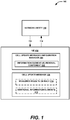
- System 100 includes a user equipment (UE) 102 that can communicate with one or more network entities 110, which may include one or more macro cell and/or femtocell network entities via one or more over-the-air links 112 and/or 114. Furthermore, the one or more network entities 110 may each be associated with a macro cell or a femtocell, each of which may be a candidate for receiving a cell update message 108 from UE 102.
- UE user equipment
- UE 102 may be configured to transmit one or more messages to network entity 110 over the link 114 and/or receive one or more message from network entity 110 over the link 112.
- the messages transmitted from UE 102 to network entity 110 may include, but are not limited to, cell update messages 108, measurement reports, data packets, signaling messages, cell discovery indicators, cell ranking information, handover target cell selection, etc.
- UE 102 may include cell update message configuration manager 104 to dynamically configure a cell update message 108 at UE 102.
- UE 102 may be configured to include an information element (IE) removal component 106 to remove or exclude one or more IEs, for example, additional information elements 112, from cell update message 108 until the size of the cell update message is at or below a threshold value configured by the network entity 110.
- IE information element
- IE removal component 106 may be configured remove one or more additional IEs 112 from the cell update message when a size of the cell update message at the UE is above a threshold value after a "measured results on random access channel (RACH)" information element (IE) 110 is excluded from the cell update message.
- the threshold value may be configured by an operator of network entity 110. For example, the operator of network entity 110 may configure the threshold size to twenty one bytes.
- UE 102 may be a mobile apparatus and may also be referred to by those skilled in the art as a mobile station, a subscriber station, a mobile unit, a subscriber unit, a wireless unit, a remote unit, a mobile device, a wireless device, a wireless communications device, a remote device, a mobile subscriber station, an access terminal, a mobile terminal, a wireless terminal, a remote terminal, a handset, a terminal, a user agent, a mobile client, a client, or some other suitable terminology.
- network entity 110 of system 100 may include one or more of any type of network components, such as an access point, including a base station (BS) or a Node B, eNodeB, a macro base station, a small base station, for example, a microcell, a femtocell, or a pico cell, a relay, a peer-to-peer device, an authentication, authorization and accounting (AAA) server, a mobile switching center (MSC), a radio network controller (RNC), etc.
- BS base station
- eNodeB eNodeB
- macro base station for example, a microcell, a femtocell, or a pico cell
- AAA authentication, authorization and accounting
- MSC mobile switching center
- RNC radio network controller
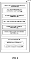
- FIG. 2 illustrates, for example, a more detailed aspect of cell update message configuration manager 104, which may be configured to dynamically configure a cell update message 108 at UE 102 by determining that the size of a cell update message at the UE is above a threshold value after a "measured results on random access channel (RACH)" information element (IE) 110 is excluded from cell update message 108, and by removing one or more additional IEs 112 from cell update message 108 until the size of the cell update message is at or below the threshold value.
- cell update message configuration manager 104 may be configured to include cell update message size determining component 202, information element (IE) removal component 106, call type determining component 206, domain status determining component 208, and establishment cause determining component 210.
- IE information element
- cell update message size determining component 202 can be configured to determine the size of cell update message 108 and compare the determined size with a threshold value. For example, the cell update message size determining component 202 can calculate the size of the cell update message prior to sending the cell update message to network entity 110. If the size of the cell update message is higher than the size configured/recognized by network entity 110, the network entity 110 may not receive and/or process the cell update message from UE 102, resulting in a failure of the cell update procedure which may impact the performance of UE 102 and/or network entity 110.
- information element (IE) removal component 204 checks if a "measured results on random access channel (RACH)" information element (IE) 110 is removed from cell update message 108. If not, information element (IE) removal component 204 removes "measured results on random access channel (RACH)" IE 110 from the cell update message, and the size of the cell update message is measured again by cell update message size determining component 202 prior to sending the cell update message to network entity 110.
- RACH random access channel
- IE removal component 204 is configured to remove one or more additional IEs 112 until the size of cell update message 108 is at or below the threshold value.
- IE removal component 204 may be configured to select the one or more additional IEs 112 to be removed from the cell update message from a list that includes one or more of a "Support for Two DRX schemes in URA_PCH and CELL_PCH” IE, a "High-Speed Physical Downlink Shared Channel (HS-PDSCH) in CELL_FACH” IE, a "Support of High Speed Downlink Shared Channel (HS-DSCH) DRX operation” IE, a "Support of common Enhanced uplink Dedicated Channel (E-DCH)" IE, a "Support of Media Access Control (MAC)-i/is” IE, a "Support of Semi-Persistent scheduling (SPS) operation” IE, a "Support of Control Channel discontinuous reception (DRX) operation” IE, a "HS-PDSCH in CELL_FACH” IE, a “START value” IE for an inactive domain, and an "establ
- IE removal component 204 may be configured to remove the one or more additional IEs 112 in a certain order, or based on a relative priority associated with each of the one or more additional IEs 112, where the order or priority may be defined by an operator and/or determined based on a given network configuration.
- cell update message size determining component 202 checks the size of cell update message 108 after "measured results on RACH" IE 110 is removed from the cell update message. If the size of the cell update message is above the threshold value, IE removal component 204 removes "Support for Two DRX schemes in URA_PCH and CELL_PCH” IE from the cell update message. The size of the cell update message is checked after removes "Support for Two DRX schemes in URA_PCH and CELL_PCH" IE is removed from the cell update message.
- call type determining component 206 may be configured to determine whether the cell update procedure that triggered the cell update message is initiated due a circuit switched (CS) call, for example, based on information from the cell update procedure.
- CS circuit switched
- IE removal component 204 removes or excludes one or more of "HS-PDSCH In CELL_FACH” IE, "Support of HS-DSCH DRX operation” IE, "Support of common .E-DCH” IE, "Support of MAC-i/is” IE and “Support of SPS operation” IE from the cell update message.
- call type determining component 206 may be configured determines whether the cell update procedure that triggered the cell update message is initiated due a packet switched (PS) call, for example, based on information from the cell update procedure. If the cell type determining component 206 determines that the cell update message is triggered due to a PS call, call type determining component 206 further determines whether network entity 106 to which the cell update message is being sent supports HS-DSCH in CELL_FACH mode.
- PS packet switched
- IE removal component 204 removes or excludes one or more of "Support of HS-DSCH DRX operation" IE, "Support of common E-DCH” IE, “Support of MAC-i/is” IE, “Support of SPS operation” IE, "Support of Control Channel DRX operation” IE from the cell update message.
- call type determining component 206 determines that the cell update message is triggered due to a PS call
- call type determining component 206 further determines whether network entity 110 to which the cell update message is being sent supports enhanced uplink in CELL FACH model.
- IE removal component 204 removes or excludes "Support of HS-DSCH DRX operation" IE, "Support of common E-DCH” IE, "HS-PDSCH in CELL FACH” IE, "Support of MAC-i/is” IE, "Support of SPS operation” IE, and "Support of Control Channel DRX operation” IE from the cell update message.
- domain status determining component 208 determines whether a circuit switched or a packet switched domain is inactive. When domain status determining component 208 determines that the circuit switched domain is inactive, "START value" IE for the circuit switched domain is removed or excluded from the cell update message as the IE associated with the inactive domain may not be required. When domain status determining component 208 determines that the packet switched domain is inactive, "START value" IE for the packet switched domain is removed or excluded from the cell update message.
- establishment cause determining component 210 may determine whether establishment cause IE is included in the cell update message. If it is included, IE removal component 202 may remove or exclude establishment cause IE from the cell update message. Additionally, if the cell update message is still above the threshold, the UE could transition to an idle mode.
- the order in which the IEs are removed from the cell update message may be pre-determined or pre-configured by the network operator of network entity 110.
- the functional aspects and/or structure of the UE 102 and/or cell update configuration manager 104 ( FIGS. 1 and 2 ) described above may be utilized for dynamically configuring a cell update message at a user equipment to improve performance of a UE 102 and/or network entity 110.
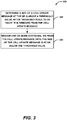
- FIG. 3 illustrates an example methodology 300 for dynamically configuring a cell update message at a user equipment (UE).
- UE user equipment
- methodology 300 may include determining that a size of the cell update message at the UE is above a threshold value after "measured results on random access channel (RACH)" information element (IE) is excluded from the cell update message.
- RACH random access channel
- UE 102 and/or cell update message configuration manager 104 and/or cell update message size determining component 202 may determine the size of a cell update message is above a threshold value after "measured results on RACH" IE 110 is removed from the cell update message.
- methodology 300 may include removing one or more IEs from the cell update message until the size of the cell update message is at or below the threshold value.
- UE 102 and/or cell update message configuration manager 104 and/or information element (IE) removal component 106 may remove one or more IEs from the cell update message until the size of the cell update message is at or below the threshold value.
- IE information element
- the one or more IEs to be removed from the cell update message can be selected from a list that includes "Support for Two DRX schemes in URA_PCH and CELL_PCH” IE, a "High-Speed Physical Downlink Shared Channel (HS-PDSCH) in CELL_FACH” IE, a “Support of High Speed Downlink Shared Channel (HS-DSCH) DRX operation” IE, a "Support of common Enhanced uplink Dedicated Channel (E-DCH)" IE, a “Support of Media Access Control (MAC)-i/is” IE, a “Support of Semi-Persistent scheduling (SPS) operation” IE, a "Support of Control Channel discontinuous reception (DRX) operation” IE, a "HS-PDSCH in CELL_FACH” IE, a “START value” IE for an inactive domain, and an “establishment cause” IE as described in Fig. 2 above.
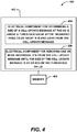
- System 400 is displayed for dynamically configuring a cell update message at a user equipment (UE).
- system 400 can reside at least partially within UE 102 ( FIG. 1 ).
- system 400 is represented as including functional blocks, which can be functional blocks that represent functions implemented by a processor, software, or a combination thereof (for example, firmware).
- System 400 includes a logical grouping 402 of electrical components that can act in conjunction.
- logical grouping 402 can include an electrical component 404 for determining that a size of the cell update message at the UE is above a threshold value after a "measured results on random access channel (RACH)" information element (IE) is excluded from the cell update message.
- electrical component 404 may comprise cell update message size determining component 202 ( FIG. 2 ).
- logical grouping 402 can include an electrical component 406 for removing one or more IEs from the cell update message until the size of the cell update message is at or below the threshold value.
- electrical component may comprise information element removal component 106 ( FIG. 1 and FIG. 2 ).
- system 400 can include a memory 408 that retains instructions for executing functions associated with the electrical components 404 and 406, stores data used or obtained by the electrical components 404 and 406. While shown as being external to memory 408, it is to be understood that one or more of the electrical components 404 and 406 can exist within memory 408.
- electrical components 404 and 406 can comprise at least one processor, or each electrical component 404 and 406 can be a corresponding module of at least one processor.
- electrical components 404 and 406 can be a computer program product including a computer readable medium, where each electrical component 404 and 406 can be corresponding code.
- any of UE 102 or network entity 110 may be represented by a specially programmed or configured computer device 500.
- computer device 500 may include cell update message configuration manager 104 and/or information element (IE) removal component 106 ( FIGS. 1 and 2 ), such as in specially programmed computer readable instructions or code, firmware, hardware, or some combination thereof.
- Computer device 500 includes a processor 502 for carrying out processing functions associated with one or more of components and functions described herein.
- Processor 502 can include a single or multiple set of processors or multi-core processors.
- processor 502 can be implemented as an integrated processing system and/or a distributed processing system.
- Computer device 500 further includes a memory 504, such as for storing data used herein and/or local versions of applications being executed by processor 502.
- Memory 504 can include any type of memory usable by a computer, such as random access memory (RAM), read only memory (ROM), tapes, magnetic discs, optical discs, volatile memory, non-volatile memory, and any combination thereof.
- computer device 500 includes a communications component 506 that provides for establishing and maintaining communications with one or more parties utilizing hardware, software, and services as described herein.
- Communications component 506 may carry communications between components on computer device 500, as well as between computer device 500 and external devices, such as devices located across a communications network and/or devices serially or locally connected to computer device 500.
- communications component 506 may include one or more buses, and may further include transmit chain components and receive chain components associated with a transmitter and receiver, respectively, or a transceiver, operable for interfacing with external devices.
- communications component 506 may be configured to receive one or more pages from one or more subscriber networks. In a further aspect, such a page may correspond to the second subscription and may be received via the first technology type communication services.
- computer device 500 may further include a data store 508, which can be any suitable combination of hardware and/or software, that provides for mass storage of information, databases, and programs employed in connection with aspects described herein.
- data store 508 may be a data repository for applications not currently being executed by processor 502 and/or any threshold values or finger position values.
- Computer device 500 may additionally include a user interface component 510 operable to receive inputs from a user of computer device 500 and further operable to generate outputs for presentation to the user.
- User interface component 510 may include one or more input devices, including but not limited to a keyboard, a number pad, a mouse, a touch-sensitive display, a navigation key, a function key, a microphone, a voice recognition component, any other mechanism capable of receiving an input from a user, or any combination thereof.
- user interface component 510 may include one or more output devices, including but not limited to a display, a speaker, a haptic feedback mechanism, a printer, any other mechanism capable of presenting an output to a user, or any combination thereof.
- FIG. 6 is a block diagram illustrating an example of a hardware implementation for an apparatus 600 employing a processing system 614 for carrying out aspects of the present disclosure, such as methods for dynamically configuring a cell update message at a user equipment (UE), including cell update message configuration manager 104 and/or information element (IE) removal component 106 ( FIGS. 1 and 2 ).
- the processing system 614 may be implemented with bus architecture, represented generally by a bus 602.
- the bus 602 may include any number of interconnecting buses and bridges depending on the specific application of the processing system 614 and the overall design constraints.
- the bus 602 links together various circuits including one or more processors, represented generally by the processor 604, computer-readable media, represented generally by the computer-readable medium 606, and one or more components described herein, such as, but not limited to, cell update message configuration manager 104 ( FIGS. 1 and 2 ).
- the bus 602 may also link various other circuits such as timing sources, peripherals, voltage regulators, and power management circuits, which are well known in the art, and therefore, will not be described any further.
- a bus interface 608 provides an interface between the bus 602 and a transceiver 610.
- the transceiver 610 provides a means for communicating with various other apparatus over a transmission medium.
- a user interface 612 e.g., keypad, display, speaker, microphone, joystick
- the processor 604 is responsible for managing the bus 602 and general processing, including the execution of software stored on the computer-readable medium 606.
- the software when executed by the processor 604, causes the processing system 614 to perform the various functions described infra for any particular apparatus.
- the computer-readable medium 606 may also be used for storing data that is manipulated by the processor 604 when executing software.
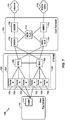
- FIG. 7 A UMTS network includes three interacting domains: a Core Network (CN) 704, a UMTS Terrestrial Radio Access Network (UTRAN) 702, and UE 104.
- CN Core Network
- UTRAN UMTS Terrestrial Radio Access Network
- UE 710 may be UE 102 ( FIG.
- UTRAN 702 may be configured to perform functions thereof, for example, including dynamically configuring a cell update message by cell update message configuration manager 104.
- UTRAN 702 may comprise a RAT network entity 106 ( FIG. 1 ), which in this case may be respective ones of the Node Bs 708.
- UTRAN 702 provides various wireless services including telephony, video, data, messaging, broadcasts, and/or other services.
- the UTRAN 702 may include a plurality of Radio Network Subsystems (RNSs) such as an RNS 707, each controlled by a respective Radio Network Controller (RNC) such as an RNC 706.
- RNSs Radio Network Subsystems
- RNC Radio Network Controller
- the UTRAN 702 may include any number of RNCs 706 and RNSs 707 in addition to the RNCs 706 and RNSs 707 illustrated herein.
- the RNC 706 is an apparatus responsible for, among other things, assigning, reconfiguring, and releasing radio resources within the RNS 707.
- the RNC 706 may be interconnected to other RNCs (not shown) in the UTRAN 702 through various types of interfaces such as a direct physical connection, a virtual network, or the like, using any suitable transport network.
- Communication between UE 710 and Node B 708 may be considered as including a physical (PHY) layer and a medium access control (MAC) layer. Further, communication between UE 710 and RNC 706 by way of a respective Node B 708 may be considered as including a radio resource control (RRC) layer.
- RRC radio resource control
- the PHY layer may be considered layer 1; the MAC layer may be considered layer 7; and the RRC layer may be considered layer 3.
- Information herein below utilizes terminology introduced in the RRC Protocol Specification, 3GPP TS 75.331 v9.1.0, incorporated herein by reference.
- the geographic region covered by the RNS 707 may be divided into a number of cells, with a radio transceiver apparatus serving each cell.
- a radio transceiver apparatus is commonly referred to as a NodeB in UMTS applications, but may also be referred to by those skilled in the art as a base station (BS), a base transceiver station (BTS), a radio base station, a radio transceiver, a transceiver function, a basic service set (BSS), an extended service set (ESS), an access point (AP), or some other suitable terminology.
- BS basic service set
- ESS extended service set
- AP access point
- three Node Bs 708 are shown in each RNS 707; however, the RNSs 707 may include any number of wireless Node Bs.
- the Node Bs 708 provide wireless access points to a CN 704 for any number of mobile apparatuses, such as UE 102 or 710, and may be macro cell network entity 106 or optional femtocell network entity 108 of FIG. 1 .
- Examples of a mobile apparatus include a cellular phone, a smart phone, a session initiation protocol (SIP) phone, a laptop, a notebook, a netbook, a smartbook, a personal digital assistant (PDA), a satellite radio, a global positioning system (GPS) device, a multimedia device, a video device, a digital audio player (e.g., MP3 player), a camera, a game console, or any other similar functioning device.
- SIP session initiation protocol
- PDA personal digital assistant
- GPS global positioning system
- the mobile apparatus in this case is commonly referred to as a UE in UMTS applications, but may also be referred to by those skilled in the art as a mobile station, a subscriber station, a mobile unit, a subscriber unit, a wireless unit, a remote unit, a mobile device, a wireless device, a wireless communications device, a remote device, a mobile subscriber station, an access terminal, a mobile terminal, a wireless terminal, a remote terminal, a handset, a terminal, a user agent, a mobile client, a client, or some other suitable terminology.
- the UE 710 may further include a universal subscriber identity module (USIM) 711, which contains a user's subscription information to a network.
- USIM universal subscriber identity module
- one UE 710 is shown in communication with a number of the Node Bs 708.
- the DL also called the forward link, refers to the communication link from a NodeB 708 to a UE 710
- the UL also called the reverse link, refers to the communication link from a UE 710 to a NodeB 708.
- the CN 704 interfaces with one or more access networks, such as the UTRAN 702. As shown, the CN 704 is a GSM core network. However, as those skilled in the art will recognize, the various concepts presented throughout this disclosure may be implemented in a RAN, or other suitable access network, to provide UEs with access to types of CNs other than GSM networks.
- the CN 704 includes a circuit-switched (CS) domain and a packet-switched (PS) domain.
- Some of the circuit-switched elements are a Mobile services Switching Centre (MSC), a Visitor location register (VLR) and a Gateway MSC.
- Packet-switched elements include a Serving GPRS Support Node (SGSN) and a Gateway GPRS Support Node (GGSN).
- Some network elements, like EIR, HLR, VLR and AuC may be shared by both of the circuit-switched and packet-switched domains.
- the CN 704 supports circuit-switched services with a MSC 712 and a GMSC 714.
- the GMSC 714 may be referred to as a media gateway (MGW).
- MGW media gateway
- One or more RNCs, such as the RNC 706, may be connected to the MSC 712.
- the MSC 712 is an apparatus that controls call setup, call routing, and UE mobility functions.
- the MSC 712 also includes a VLR that contains subscriber-related information for the duration that a UE is in the coverage area of the MSC 712.
- the GMSC 714 provides a gateway through the MSC 712 for the UE to access a circuit-switched network 716.
- the GMSC 714 includes a home location register (HLR) 715 containing subscriber data, such as the data reflecting the details of the services to which a particular user has subscribed.
- HLR home location register
- the HLR is also associated with an authentication center (AuC) that contains subscriber-specific authentication data.
- AuC authentication center
- the GMSC 714 queries the HLR 715 to determine the UE's location and forwards the call to the particular MSC serving that location.
- the CN 704 also supports packet-data services with a serving GPRS support node (SGSN) 718 and a gateway GPRS support node (GGSN) 720.
- GPRS which stands for General Packet Radio Service, is designed to provide packet-data services at speeds higher than those available with standard circuit-switched data services.
- the GGSN 720 provides a connection for the UTRAN 702 to a packet-based network 722.
- the packet-based network 722 may be the Internet, a private data network, or some other suitable packet-based network.
- the primary function of the GGSN 720 is to provide the UEs 710 with packet-based network connectivity. Data packets may be transferred between the GGSN 720 and the UEs 710 through the SGSN 718, which performs primarily the same functions in the packet-based domain as the MSC 712 performs in the circuit-switched domain.
- An air interface for UMTS may utilize a spread spectrum Direct-Sequence Code Division Multiple Access (DS-CDMA) system.
- the spread spectrum DS-CDMA spreads user data through multiplication by a sequence of pseudorandom bits called chips.
- the "wideband" W-CDMA air interface for UMTS is based on such direct sequence spread spectrum technology and additionally calls for a frequency division duplexing (FDD).
- FDD uses a different carrier frequency for the UL and DL between a NodeB 708 and a UE 710.
- Another air interface for UMTS that utilizes DS-CDMA, and uses time division duplexing (TDD), is the TD-SCDMA air interface.
- TD-SCDMA time division duplexing
- HSPA air interface includes a series of enhancements to the 3G/W-CDMA air interface, facilitating greater throughput and reduced latency.
- HSPA utilizes hybrid automatic repeat request (HARQ), shared channel transmission, and adaptive modulation and coding.
- HARQ hybrid automatic repeat request
- the standards that define HSPA include HSDPA (high speed downlink packet access) and HSUPA (high speed uplink packet access, also referred to as enhanced uplink, or EUL).
- HSDPA utilizes as its transport channel the high-speed downlink shared channel (HS-DSCH).
- the HS-DSCH is implemented by three physical channels: the high-speed physical downlink shared channel (HS-PDSCH), the high-speed shared control channel (HS-SCCH), and the high-speed dedicated physical control channel (HS-DPCCH).
- HS-PDSCH high-speed physical downlink shared channel
- HS-SCCH high-speed shared control channel
- HS-DPCCH high-speed dedicated physical control channel
- the HS-DPCCH carries the HARQ ACK/NACK signaling on the uplink to indicate whether a corresponding packet transmission was decoded successfully. That is, with respect to the downlink, the UE 710 provides feedback to Node B 708 over the HS-DPCCH to indicate whether it correctly decoded a packet on the downlink.
- HS-DPCCH further includes feedback signaling from the UE 710 to assist the Node B 708 in taking the right decision in terms of modulation and coding scheme and precoding weight selection, this feedback signaling including the CQI and PCI.
- HSPA Evolved or HSPA+ is an evolution of the HSPA standard that includes MIMO and 64-QAM, enabling increased throughput and higher performance. That is, in an aspect of the disclosure, the Node B 708 and/or the UE 710 may have multiple antennas supporting MIMO technology. The use of MIMO technology enables the Node B 708 to exploit the spatial domain to support spatial multiplexing, beamforming, and transmit diversity.
- MIMO Multiple Input Multiple Output
- MIMO systems generally enhance data transmission performance, enabling diversity gains to reduce multipath fading and increase transmission quality, and spatial multiplexing gains to increase data throughput.
- Spatial multiplexing may be used to transmit different streams of data simultaneously on the same frequency.
- the data steams may be transmitted to a single UE 710 to increase the data rate or to multiple UEs 710 to increase the overall system capacity. This is achieved by spatially precoding each data stream and then transmitting each spatially precoded stream through a different transmit antenna on the downlink.
- the spatially precoded data streams arrive at the UE(s) 710 with different spatial signatures, which enables each of the UE(s) 710 to recover the one or more the data streams destined for that UE 710.
- each UE 710 may transmit one or more spatially precoded data streams, which enables Node B 708 to identify the source of each spatially precoded data stream.
- Spatial multiplexing may be used when channel conditions are good.
- beamforming may be used to focus the transmission energy in one or more directions, or to improve transmission based on characteristics of the channel. This may be achieved by spatially precoding a data stream for transmission through multiple antennas. To achieve good coverage at the edges of the cell, a single stream beamforming transmission may be used in combination with transmit diversity.
- n transport blocks may be transmitted simultaneously over the same carrier utilizing the same channelization code. Note that the different transport blocks sent over the n transmit antennas may have the same or different modulation and coding schemes from one another.
- Single Input Multiple Output generally refers to a system utilizing a single transmit antenna (a single input to the channel) and multiple receive antennas (multiple outputs from the channel).
- a single transport block is sent over the respective carrier.
- an access network 800 in a UTRAN architecture may include one or more UEs configured to include cell update message configuration manager 104 and/or information element (IE) removal component 106 ( FIGs. 1 and 2 ) for determining reselection parameters for detected cells.
- the multiple access wireless communication system includes multiple cellular regions (cells), including cells 802, 804, and 806, each of which may include one or more sectors.
- the multiple sectors can be formed by groups of antennas with each antenna responsible for communication with UEs in a portion of the cell. For example, in cell 802, antenna groups 812, 814, and 816 may each correspond to a different sector. In cell 804, antenna groups 818, 820, and 822 each correspond to a different sector.
- antenna groups 824, 826, and 828 each correspond to a different sector.
- the cells 802, 804 and 806 may include several wireless communication devices, e.g., User Equipment or UEs, for example, including reselection manager 105 of Fig. 1 , which may be in communication with one or more sectors of each cell 802, 804 or 806.
- UEs 830 and 832 may be in communication with NodeB 842
- UEs 834 and 836 may be in communication with NodeB 844
- UEs 838 and 840 can be in communication with NodeB 846.
- each NodeB 842, 844, 846 is configured to provide an access point to a CN 704 ( FIG.
- each NodeB 842, 844, 846 and UEs 830, 832, 834, 836, 838, 840 may be UE 102 of FIG. 1 and may perform the methods outlined herein.
- a serving cell change (SCC) or handover may occur in which communication with the UE 834 transitions from the cell 804, which may be referred to as the source cell, to cell 806, which may be referred to as the target cell.
- Management of the handover procedure may take place at the UE 834, at the Node Bs corresponding to the respective cells, at a radio network controller 706 ( FIG. 7 ), or at another suitable node in the wireless network.
- the UE 834 may monitor various parameters of the source cell 804 as well as various parameters of neighboring cells such as cells 806 and 802.
- the UE 834 may maintain communication with one or more of the neighboring cells. During this time, the UE 834 may maintain an Active Set, that is, a list of cells that the UE 834 is simultaneously connected to (e.g., the UTRA cells that are currently assigning a downlink dedicated physical channel DPCH or fractional downlink dedicated physical channel F-DPCH to the UE 834 may constitute the Active Set). In any case, UE 834 may execute reselection manager 104 to perform the reselection operations described herein.
- an Active Set that is, a list of cells that the UE 834 is simultaneously connected to (e.g., the UTRA cells that are currently assigning a downlink dedicated physical channel DPCH or fractional downlink dedicated physical channel F-DPCH to the UE 834 may constitute the Active Set).
- UE 834 may execute reselection manager 104 to perform the reselection operations described herein.
- the modulation and multiple access scheme employed by the access network 700 may vary depending on the particular telecommunications standard being deployed.
- the standard may include Evolution-Data Optimized (EV-DO) or Ultra Mobile Broadband (UMB).
- EV-DO and UMB are air interface standards promulgated by the 3rd Generation Partnership Project 2 (3GPP2) as part of the CDMA2000 family of standards and employs CDMA to provide broadband Internet access to mobile stations.
- 3GPP2 3rd Generation Partnership Project 2
- the standard may alternately be Universal Terrestrial Radio Access (UTRA) employing Wideband-CDMA (W-CDMA) and other variants of CDMA, such as TD-SCDMA; Global System for Mobile Communications (GSM) employing TDMA; and Evolved UTRA (E-UTRA), Ultra Mobile Broadband (UMB), IEEE 802.11 (Wi-Fi), IEEE 802.16 (WiMAX), IEEE 802.20, and Flash-OFDM employing OFDMA.
- UTRA, E-UTRA, UMTS, LTE, LTE Advanced, and GSM are described in documents from the 3GPP organization.
- CDMA2000 and UMB are described in documents from the 3GPP2 organization.
- the actual wireless communication standard and the multiple access technology employed will depend on the specific application and the overall design constraints imposed on the system.
- the radio protocol architecture may take on various forms depending on the particular application.
- An example for an HSPA system will now be presented with reference to FIG. 9.
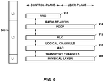
- FIG. 9 is a conceptual diagram illustrating an example of the radio protocol architecture for the user and control planes.
- the radio protocol architecture for the UE for example, UE 102 of Fig. 1 configured to include cell update message configuration manager 104 and/or information element (IE) removal component 106 ( FIGs. 1 and 2 ) for dynamically configuring a cell updating message, and a Node B is shown with three layers: Layer 1, Layer 2, and Layer 3.
- Layer 1 is the lowest lower and implements various physical layer signal processing functions. Layer 1 will be referred to herein as the physical layer 906.
- Layer 2 (L2 layer) 908 is above the physical layer 906 and is responsible for the link between the UE and node B over the physical layer 906.
- the L2 layer 908 includes a media access control (MAC) sublayer 910, a radio link control (RLC) sublayer 912, and a packet data convergence protocol (PDCP) 914 sublayer, which are terminated at the node B on the network side.
- MAC media access control
- RLC radio link control
- PDCP packet data convergence protocol
- the UE may have several upper layers above the L2 layer 908 including a network layer (e.g., IP layer) that is terminated at a PDN gateway on the network side, and an application layer that is terminated at the other end of the connection (e.g., far end UE, server, etc.).
- IP layer e.g., IP layer
- the PDCP sublayer 914 provides multiplexing between different radio bearers and logical channels.
- the PDCP sublayer 914 also provides header compression for upper layer data packets to reduce radio transmission overhead, security by ciphering the data packets, and handover support for UEs between NodeBs.
- the RLC sublayer 912 provides segmentation and reassembly of upper layer data packets, retransmission of lost data packets, and reordering of data packets to compensate for out-of-order reception due to hybrid automatic repeat request (HARQ).
- HARQ hybrid automatic repeat request
- the MAC sublayer 910 provides multiplexing between logical and transport channels.
- the MAC sublayer 910 is also responsible for allocating the various radio resources (e.g., resource blocks) in one cell among the UEs.
- the MAC sublayer 910 is also responsible for HARQ operations.
- the radio protocol architecture for the UE and eNB is substantially the same for the physical layer 906 and the L2 layer 908 with the exception that there is no header compression function for the control plane.
- the control plane also includes a radio resource control (RRC) sublayer 916 in Layer 3 (L3 layer).
- RRC sublayer 916 is responsible for obtaining radio resources (i.e., radio bearers) and for configuring the lower layers using RRC signaling between the eNB and the UE.
- processors include microprocessors, microcontrollers, digital signal processors (DSPs), field programmable gate arrays (FPGAs), programmable logic devices (PLDs), state machines, gated logic, discrete hardware circuits, and other suitable hardware configured to perform the various functionality described throughout this disclosure.
- DSPs digital signal processors
- FPGAs field programmable gate arrays
- PLDs programmable logic devices
- state machines gated logic, discrete hardware circuits, and other suitable hardware configured to perform the various functionality described throughout this disclosure.
- One or more processors in the processing system may execute software.
- Software shall be construed broadly to mean instructions, instruction sets, code, code segments, program code, programs, subprograms, software modules, applications, software applications, software packages, routines, subroutines, objects, executables, threads of execution, procedures, functions, etc., whether referred to as software, firmware, middleware, microcode, hardware description language, or otherwise.
- the software may reside on a computer-readable medium.
- the computer-readable medium may be a non-transitory computer-readable medium.
- a non-transitory computer-readable medium includes, by way of example, a magnetic storage device (e.g., hard disk, floppy disk, magnetic strip), an optical disk (e.g., compact disk (CD), digital versatile disk (DVD)), a smart card, a flash memory device (e.g., card, stick, key drive), random access memory (RAM), read only memory (ROM), programmable ROM (PROM), erasable PROM (EPROM), electrically erasable PROM (EEPROM), a register, a removable disk, and any other suitable medium for storing software and/or instructions that may be accessed and read by a computer.
- a magnetic storage device e.g., hard disk, floppy disk, magnetic strip
- an optical disk e.g., compact disk (CD), digital versatile disk (DVD)
- a smart card e.g., a flash memory device (e.g., card, stick, key drive), random access memory (RAM), read only memory (ROM), programmable ROM
- the computer-readable medium may also include, by way of example, a carrier wave, a transmission line, and any other suitable medium for transmitting software and/or instructions that may be accessed and read by a computer.
- the computer-readable medium may be resident in the processing system, external to the processing system, or distributed across multiple entities including the processing system.
- the computer-readable medium may be embodied in a computer-program product.
- a computer-program product may include a computer-readable medium in packaging materials.
Description
- Aspects of the present disclosure relate generally to wireless communication systems, and more particularly, to configuration of cell update message.
- Wireless communication networks are widely deployed to provide various communication services such as telephony, video, data, messaging, broadcasts, and so on. Such networks, which are usually multiple access networks, support communications for multiple users by sharing the available network resources. One example of such a network is the UMTS Terrestrial Radio Access Network (UTRAN). The UTRAN is the radio access network (RAN) defined as a part of the Universal Mobile Telecommunications System (UMTS), a third generation (3G) mobile phone technology supported by the 3rd Generation Partnership Project (3GPP). The UMTS, which is the successor to Global System for Mobile Communications (GSM) technologies, currently supports various air interface standards, such as Wideband-Code Division Multiple Access (W-CDMA), Time Division-Code Division Multiple Access (TD-CDMA), and Time Division-Synchronous Code Division Multiple Access (TD-SCDMA). The UMTS also supports enhanced 3G data communications protocols, such as High Speed Packet Access (HSPA), which provides higher data transfer speeds and capacity to associated UMTS networks.
- In UMTS networks, a user equipment (UE) indicates the capabilities of the UE to a base station and/or a network in a cell update message. In legacy networks, for example, networks based on 3GPP pre-release 8 standards, the size of the cell update message is generally configured by the network, for example, to 21 bytes.
- For UEs that can support 3GPP Release 8 (or later), the UEs can support additional features and indicate these new capabilities in a cell update message to the network. However, the size of the cell update message from the UE may exceed the size configured by the network and may result in failure of cell update procedure. One approach to address this problem is to reduce the size of the cell update message by removing a "Measured Results on RACH" information element (IE) from the cell update message. But, the size of the cell update message may still exceed the size configured by the network even after the "Measured Results on RACH" IE is removed from the cell update message.
-
KR 2010 0110033 WO 2008/072005 relates to a method for fitting a message response into a frame size. A maximum permitted frame size for a network response is determined. If the response exceeds the maximum frame size, the information elements with the lowest priority are removed until the response is within the maximum frame size.WO 2005/079085 relates to a method for reducing information delay when a data transfer is initiated.US 2005/009527 relates to a wireless transmit/receive unit (WTRU) having a selectively configurable transceiver with various modes of operation.US 2005/0266846 A1 relates to a method and apparatus for providing new configurations for transmitting control information between a mobile terminal and a radio network controller using common control channel logical channel/transport channel. - Thus, there is a need for a method, an apparatus and a computer program product, for dynamically configuring a cell update message that is within the size allowed by the network without negatively impacting the performance of the UE and/or network.
- Aspects of the invention are defined in the claims.
-
-
FIG. 1 is a block diagram illustrating an example wireless system of aspects of the present disclosure; -
FIG. 2 is a block diagram illustrating an example cell update message configuration manager in aspects of the present disclosure; -
FIG. 3 is a flow diagram illustrating aspects of a method for dynamically configuring a cell update message according to aspects of the present disclosure; -
FIG. 4 is a component diagram illustrating aspects of a logical grouping of electrical components as contemplated by the present disclosure; -
FIG. 5 is a block diagram illustrating aspects of a computer device according to the present disclosure; -
FIG. 6 is a block diagram illustrating an example of a hardware implementation for an apparatus employing a processing system; -
FIG. 7 is a block diagram conceptually illustrating an example of a telecommunications system; -
FIG. 8 is a conceptual diagram illustrating an example of an access network; and -
FIG. 9 is a conceptual diagram illustrating an example of a radio protocol architecture for the user and control plane. - The detailed description set forth below in connection with the appended drawings is intended as a description of various configurations and is not intended to represent the only configurations in which the concepts described herein may be practiced. The detailed description includes specific details for the purpose of providing a thorough understanding of various concepts. However, it will be apparent to those skilled in the art that these concepts may be practiced without these specific details. In some instances, well known structures and components are shown in block diagram form in order to avoid obscuring such concepts.
- The present disclosure provides a method, an apparatus and a computer program product, for dynamically configuring a cell update message at a user equipment by determining that a size of the cell update message at the UE is above a threshold value after a "measured results on random access channel (RACH)" information element (IE) is excluded from the cell update message, and removing one or more IEs from the cell update message until the size of the cell update message is at or below the threshold value.
- Referring to
FIG. 1 , awireless communication system 100 is illustrated that facilitates dynamically configuring a cell update message.System 100 includes a user equipment (UE) 102 that can communicate with one ormore network entities 110, which may include one or more macro cell and/or femtocell network entities via one or more over-the-air links 112 and/or 114. Furthermore, the one ormore network entities 110 may each be associated with a macro cell or a femtocell, each of which may be a candidate for receiving acell update message 108 from UE 102. - In an aspect, UE 102 may be configured to transmit one or more messages to
network entity 110 over thelink 114 and/or receive one or more message fromnetwork entity 110 over thelink 112. In an aspect, the messages transmitted from UE 102 tonetwork entity 110 may include, but are not limited to,cell update messages 108, measurement reports, data packets, signaling messages, cell discovery indicators, cell ranking information, handover target cell selection, etc. - In an aspect, UE 102 may include cell update
message configuration manager 104 to dynamically configure acell update message 108 at UE 102. In an aspect, for example, UE 102 may be configured to include an information element (IE)removal component 106 to remove or exclude one or more IEs, for example,additional information elements 112, fromcell update message 108 until the size of the cell update message is at or below a threshold value configured by thenetwork entity 110. - In an additional or optional aspect,
IE removal component 106 may be configured remove one or moreadditional IEs 112 from the cell update message when a size of the cell update message at the UE is above a threshold value after a "measured results on random access channel (RACH)" information element (IE) 110 is excluded from the cell update message. In an additional aspect, the threshold value may be configured by an operator ofnetwork entity 110. For example, the operator ofnetwork entity 110 may configure the threshold size to twenty one bytes. - In an additional aspect, UE 102 may be a mobile apparatus and may also be referred to by those skilled in the art as a mobile station, a subscriber station, a mobile unit, a subscriber unit, a wireless unit, a remote unit, a mobile device, a wireless device, a wireless communications device, a remote device, a mobile subscriber station, an access terminal, a mobile terminal, a wireless terminal, a remote terminal, a handset, a terminal, a user agent, a mobile client, a client, or some other suitable terminology.
- Additionally,
network entity 110 ofsystem 100 may include one or more of any type of network components, such as an access point, including a base station (BS) or a Node B, eNodeB, a macro base station, a small base station, for example, a microcell, a femtocell, or a pico cell, a relay, a peer-to-peer device, an authentication, authorization and accounting (AAA) server, a mobile switching center (MSC), a radio network controller (RNC), etc. -
FIG. 2 illustrates, for example, a more detailed aspect of cell updatemessage configuration manager 104, which may be configured to dynamically configure acell update message 108 at UE 102 by determining that the size of a cell update message at the UE is above a threshold value after a "measured results on random access channel (RACH)" information element (IE) 110 is excluded fromcell update message 108, and by removing one or moreadditional IEs 112 fromcell update message 108 until the size of the cell update message is at or below the threshold value. In an example aspect, cell updatemessage configuration manager 104 may be configured to include cell update messagesize determining component 202, information element (IE)removal component 106, calltype determining component 206, domain status determining component 208, and establishment cause determining component 210. - In an aspect, cell update message
size determining component 202 can be configured to determine the size ofcell update message 108 and compare the determined size with a threshold value. For example, the cell update messagesize determining component 202 can calculate the size of the cell update message prior to sending the cell update message tonetwork entity 110. If the size of the cell update message is higher than the size configured/recognized bynetwork entity 110, thenetwork entity 110 may not receive and/or process the cell update message from UE 102, resulting in a failure of the cell update procedure which may impact the performance of UE 102 and/ornetwork entity 110. - In an additional or optional aspect, if the size of the cell update message is above a threshold value, information element (IE) removal component 204 checks if a "measured results on random access channel (RACH)" information element (IE) 110 is removed from
cell update message 108. If not, information element (IE) removal component 204 removes "measured results on random access channel (RACH)"IE 110 from the cell update message, and the size of the cell update message is measured again by cell update messagesize determining component 202 prior to sending the cell update message tonetwork entity 110. If so, or if the cell update message is measured to exceed the threshold value after removal of "measured results on random access channel (RACH)" information element (IE) 110, then IE removal component 204 is configured to remove one or moreadditional IEs 112 until the size ofcell update message 108 is at or below the threshold value. - In an example aspect, IE removal component 204 may be configured to select the one or more
additional IEs 112 to be removed from the cell update message from a list that includes one or more of a "Support for Two DRX schemes in URA_PCH and CELL_PCH" IE, a "High-Speed Physical Downlink Shared Channel (HS-PDSCH) in CELL_FACH" IE, a "Support of High Speed Downlink Shared Channel (HS-DSCH) DRX operation" IE, a "Support of common Enhanced uplink Dedicated Channel (E-DCH)" IE, a "Support of Media Access Control (MAC)-i/is" IE, a "Support of Semi-Persistent scheduling (SPS) operation" IE, a "Support of Control Channel discontinuous reception (DRX) operation" IE, a "HS-PDSCH in CELL_FACH" IE, a "START value" IE for an inactive domain, and an "establishment cause" IE. In an optional aspect, the detailed description foradditional IEs 112 above can be found in 3GPP Specification. In an optional aspect, IE removal component 204 may be configured to remove the one or moreadditional IEs 112 in a certain order, or based on a relative priority associated with each of the one or moreadditional IEs 112, where the order or priority may be defined by an operator and/or determined based on a given network configuration. - As such, in an aspect, cell update message
size determining component 202 checks the size ofcell update message 108 after "measured results on RACH"IE 110 is removed from the cell update message. If the size of the cell update message is above the threshold value, IE removal component 204 removes "Support for Two DRX schemes in URA_PCH and CELL_PCH" IE from the cell update message. The size of the cell update message is checked after removes "Support for Two DRX schemes in URA_PCH and CELL_PCH" IE is removed from the cell update message. - In an aspect, once "Support for Two DRX schemes in URA_PCH and CELL PCH" IE is removed from the cell update message, and the size of the cell update message is determined to be above the threshold value, call
type determining component 206 may be configured to determine whether the cell update procedure that triggered the cell update message is initiated due a circuit switched (CS) call, for example, based on information from the cell update procedure. If the celltype determining component 206 determines that the cell update message is triggered due to a CS call, IE removal component 204 removes or excludes one or more of "HS-PDSCH In CELL_FACH" IE, "Support of HS-DSCH DRX operation" IE, "Support of common .E-DCH" IE, "Support of MAC-i/is" IE and "Support of SPS operation" IE from the cell update message. - In another aspect, call
type determining component 206 may be configured determines whether the cell update procedure that triggered the cell update message is initiated due a packet switched (PS) call, for example, based on information from the cell update procedure. If the celltype determining component 206 determines that the cell update message is triggered due to a PS call, calltype determining component 206 further determines whethernetwork entity 106 to which the cell update message is being sent supports HS-DSCH in CELL_FACH mode. If the calltype determining component 206 determines that thenetwork entity 110 does not support HS-DSCH in CELL FACH mode, IE removal component 204 removes or excludes one or more of "Support of HS-DSCH DRX operation" IE, "Support of common E-DCH" IE, "Support of MAC-i/is" IE, "Support of SPS operation" IE, "Support of Control Channel DRX operation" IE from the cell update message. - In an additional or alternative aspect, when call
type determining component 206 determines that the cell update message is triggered due to a PS call, calltype determining component 206 further determines whethernetwork entity 110 to which the cell update message is being sent supports enhanced uplink in CELL FACH model. If calltype determining component 206 determines thatnetwork entity 110 does not support enhanced uplink in CELL FACH mode, IE removal component 204 removes or excludes "Support of HS-DSCH DRX operation" IE, "Support of common E-DCH" IE, "HS-PDSCH in CELL FACH" IE, "Support of MAC-i/is" IE, "Support of SPS operation" IE, and "Support of Control Channel DRX operation" IE from the cell update message. - In an aspect, domain status determining component 208 determines whether a circuit switched or a packet switched domain is inactive. When domain status determining component 208 determines that the circuit switched domain is inactive, "START value" IE for the circuit switched domain is removed or excluded from the cell update message as the IE associated with the inactive domain may not be required. When domain status determining component 208 determines that the packet switched domain is inactive, "START value" IE for the packet switched domain is removed or excluded from the cell update message.
- In an aspect, establishment cause determining component 210 may determine whether establishment cause IE is included in the cell update message. If it is included,
IE removal component 202 may remove or exclude establishment cause IE from the cell update message. Additionally, if the cell update message is still above the threshold, the UE could transition to an idle mode. - In an aspect, the order in which the IEs are removed from the cell update message may be pre-determined or pre-configured by the network operator of
network entity 110. In addition, the functional aspects and/or structure of theUE 102 and/or cell update configuration manager 104 (FIGS. 1 and2 ) described above may be utilized for dynamically configuring a cell update message at a user equipment to improve performance of aUE 102 and/ornetwork entity 110. -
FIG. 3 illustrates anexample methodology 300 for dynamically configuring a cell update message at a user equipment (UE). - In an aspect, at
block 302,methodology 300 may include determining that a size of the cell update message at the UE is above a threshold value after "measured results on random access channel (RACH)" information element (IE) is excluded from the cell update message. For example, in an aspect,UE 102 and/or cell updatemessage configuration manager 104 and/or cell update messagesize determining component 202 may determine the size of a cell update message is above a threshold value after "measured results on RACH"IE 110 is removed from the cell update message. - In an aspect, at
block 304,methodology 300 may include removing one or more IEs from the cell update message until the size of the cell update message is at or below the threshold value. For example, in an aspect,UE 102 and/or cell updatemessage configuration manager 104 and/or information element (IE)removal component 106 may remove one or more IEs from the cell update message until the size of the cell update message is at or below the threshold value. - In an example aspect, the one or more IEs to be removed from the cell update message can be selected from a list that includes "Support for Two DRX schemes in URA_PCH and CELL_PCH" IE, a "High-Speed Physical Downlink Shared Channel (HS-PDSCH) in CELL_FACH" IE, a "Support of High Speed Downlink Shared Channel (HS-DSCH) DRX operation" IE, a "Support of common Enhanced uplink Dedicated Channel (E-DCH)" IE, a "Support of Media Access Control (MAC)-i/is" IE, a "Support of Semi-Persistent scheduling (SPS) operation" IE, a "Support of Control Channel discontinuous reception (DRX) operation" IE, a "HS-PDSCH in CELL_FACH" IE, a "START value" IE for an inactive domain, and an "establishment cause" IE as described in
Fig. 2 above. The cellupdate configuration manager 104 dynamically configures the cell update message by removing IEs as described above. - Referring to
FIG. 4 , anexample system 400 is displayed for dynamically configuring a cell update message at a user equipment (UE). For example,system 400 can reside at least partially within UE 102 (FIG. 1 ). It is to be appreciated thatsystem 400 is represented as including functional blocks, which can be functional blocks that represent functions implemented by a processor, software, or a combination thereof (for example, firmware).System 400 includes alogical grouping 402 of electrical components that can act in conjunction. For instance,logical grouping 402 can include anelectrical component 404 for determining that a size of the cell update message at the UE is above a threshold value after a "measured results on random access channel (RACH)" information element (IE) is excluded from the cell update message. In an aspect,electrical component 404 may comprise cell update message size determining component 202 (FIG. 2 ). - Additionally,
logical grouping 402 can include anelectrical component 406 for removing one or more IEs from the cell update message until the size of the cell update message is at or below the threshold value. In an aspect, electrical component may comprise information element removal component 106 (FIG. 1 andFIG. 2 ). - Furthermore,
system 400 can include amemory 408 that retains instructions for executing functions associated with theelectrical components electrical components memory 408, it is to be understood that one or more of theelectrical components memory 408. In one example,electrical components electrical component electrical components electrical component - Referring to
FIG. 5 , in an aspect, any ofUE 102 or network entity 110 (FIG. 1 ) may be represented by a specially programmed or configuredcomputer device 500. In one aspect of UE implementation (for example,UE 102 ofFIG. 1 ),computer device 500 may include cell updatemessage configuration manager 104 and/or information element (IE) removal component 106 (FIGS. 1 and2 ), such as in specially programmed computer readable instructions or code, firmware, hardware, or some combination thereof.Computer device 500 includes aprocessor 502 for carrying out processing functions associated with one or more of components and functions described herein.Processor 502 can include a single or multiple set of processors or multi-core processors. Moreover,processor 502 can be implemented as an integrated processing system and/or a distributed processing system. -
Computer device 500 further includes amemory 504, such as for storing data used herein and/or local versions of applications being executed byprocessor 502.Memory 504 can include any type of memory usable by a computer, such as random access memory (RAM), read only memory (ROM), tapes, magnetic discs, optical discs, volatile memory, non-volatile memory, and any combination thereof. - Further,
computer device 500 includes acommunications component 506 that provides for establishing and maintaining communications with one or more parties utilizing hardware, software, and services as described herein.Communications component 506 may carry communications between components oncomputer device 500, as well as betweencomputer device 500 and external devices, such as devices located across a communications network and/or devices serially or locally connected tocomputer device 500. For example,communications component 506 may include one or more buses, and may further include transmit chain components and receive chain components associated with a transmitter and receiver, respectively, or a transceiver, operable for interfacing with external devices. In an additional aspect,communications component 506 may be configured to receive one or more pages from one or more subscriber networks. In a further aspect, such a page may correspond to the second subscription and may be received via the first technology type communication services. - Additionally,
computer device 500 may further include adata store 508, which can be any suitable combination of hardware and/or software, that provides for mass storage of information, databases, and programs employed in connection with aspects described herein. For example,data store 508 may be a data repository for applications not currently being executed byprocessor 502 and/or any threshold values or finger position values. -
Computer device 500 may additionally include a user interface component 510 operable to receive inputs from a user ofcomputer device 500 and further operable to generate outputs for presentation to the user. User interface component 510 may include one or more input devices, including but not limited to a keyboard, a number pad, a mouse, a touch-sensitive display, a navigation key, a function key, a microphone, a voice recognition component, any other mechanism capable of receiving an input from a user, or any combination thereof. Further, user interface component 510 may include one or more output devices, including but not limited to a display, a speaker, a haptic feedback mechanism, a printer, any other mechanism capable of presenting an output to a user, or any combination thereof. -
FIG. 6 is a block diagram illustrating an example of a hardware implementation for anapparatus 600 employing aprocessing system 614 for carrying out aspects of the present disclosure, such as methods for dynamically configuring a cell update message at a user equipment (UE), including cell updatemessage configuration manager 104 and/or information element (IE) removal component 106 (FIGS. 1 and2 ). In this example, theprocessing system 614 may be implemented with bus architecture, represented generally by abus 602. Thebus 602 may include any number of interconnecting buses and bridges depending on the specific application of theprocessing system 614 and the overall design constraints. Thebus 602 links together various circuits including one or more processors, represented generally by theprocessor 604, computer-readable media, represented generally by the computer-readable medium 606, and one or more components described herein, such as, but not limited to, cell update message configuration manager 104 (FIGS. 1 and2 ). Thebus 602 may also link various other circuits such as timing sources, peripherals, voltage regulators, and power management circuits, which are well known in the art, and therefore, will not be described any further. Abus interface 608 provides an interface between thebus 602 and atransceiver 610. Thetransceiver 610 provides a means for communicating with various other apparatus over a transmission medium. Depending upon the nature of the apparatus, a user interface 612 (e.g., keypad, display, speaker, microphone, joystick) may also be provided. - The
processor 604 is responsible for managing thebus 602 and general processing, including the execution of software stored on the computer-readable medium 606. The software, when executed by theprocessor 604, causes theprocessing system 614 to perform the various functions described infra for any particular apparatus. The computer-readable medium 606 may also be used for storing data that is manipulated by theprocessor 604 when executing software. - The various concepts presented throughout this disclosure may be implemented across a broad variety of telecommunication systems, network architectures, and communication standards. By way of example and without limitation, the aspects of the present disclosure illustrated in
FIG. 7 are presented with reference to aUMTS system 700 employing a W-CDMA air interface, and may include aUE 102 executing an aspect of cell updatemessage configuration manager 104 and/or information element (IE)removal component 106 ofFigs. 1 and2 . A UMTS network includes three interacting domains: a Core Network (CN) 704, a UMTS Terrestrial Radio Access Network (UTRAN) 702, andUE 104. In an aspect, as noted,UE 710 may be UE 102 (FIG. 1 ) and may be configured to perform functions thereof, for example, including dynamically configuring a cell update message by cell updatemessage configuration manager 104. Further,UTRAN 702 may comprise a RAT network entity 106 (FIG. 1 ), which in this case may be respective ones of theNode Bs 708. In this example,UTRAN 702 provides various wireless services including telephony, video, data, messaging, broadcasts, and/or other services. TheUTRAN 702 may include a plurality of Radio Network Subsystems (RNSs) such as anRNS 707, each controlled by a respective Radio Network Controller (RNC) such as anRNC 706. Here, theUTRAN 702 may include any number ofRNCs 706 andRNSs 707 in addition to theRNCs 706 andRNSs 707 illustrated herein. TheRNC 706 is an apparatus responsible for, among other things, assigning, reconfiguring, and releasing radio resources within theRNS 707. TheRNC 706 may be interconnected to other RNCs (not shown) in theUTRAN 702 through various types of interfaces such as a direct physical connection, a virtual network, or the like, using any suitable transport network. - Communication between
UE 710 andNode B 708 may be considered as including a physical (PHY) layer and a medium access control (MAC) layer. Further, communication betweenUE 710 andRNC 706 by way of arespective Node B 708 may be considered as including a radio resource control (RRC) layer. In the instant specification, the PHY layer may be considered layer 1; the MAC layer may be considered layer 7; and the RRC layer may be considered layer 3. Information herein below utilizes terminology introduced in the RRC Protocol Specification, 3GPP TS 75.331 v9.1.0, incorporated herein by reference. - The geographic region covered by the
RNS 707 may be divided into a number of cells, with a radio transceiver apparatus serving each cell. A radio transceiver apparatus is commonly referred to as a NodeB in UMTS applications, but may also be referred to by those skilled in the art as a base station (BS), a base transceiver station (BTS), a radio base station, a radio transceiver, a transceiver function, a basic service set (BSS), an extended service set (ESS), an access point (AP), or some other suitable terminology. For clarity, threeNode Bs 708 are shown in eachRNS 707; however, theRNSs 707 may include any number of wireless Node Bs. TheNode Bs 708 provide wireless access points to aCN 704 for any number of mobile apparatuses, such asUE cell network entity 106 or optionalfemtocell network entity 108 ofFIG. 1 . Examples of a mobile apparatus include a cellular phone, a smart phone, a session initiation protocol (SIP) phone, a laptop, a notebook, a netbook, a smartbook, a personal digital assistant (PDA), a satellite radio, a global positioning system (GPS) device, a multimedia device, a video device, a digital audio player (e.g., MP3 player), a camera, a game console, or any other similar functioning device. The mobile apparatus in this case is commonly referred to as a UE in UMTS applications, but may also be referred to by those skilled in the art as a mobile station, a subscriber station, a mobile unit, a subscriber unit, a wireless unit, a remote unit, a mobile device, a wireless device, a wireless communications device, a remote device, a mobile subscriber station, an access terminal, a mobile terminal, a wireless terminal, a remote terminal, a handset, a terminal, a user agent, a mobile client, a client, or some other suitable terminology. - In a UMTS system, the
UE 710 may further include a universal subscriber identity module (USIM) 711, which contains a user's subscription information to a network. For illustrative purposes, oneUE 710 is shown in communication with a number of theNode Bs 708. The DL, also called the forward link, refers to the communication link from aNodeB 708 to aUE 710, and the UL, also called the reverse link, refers to the communication link from aUE 710 to aNodeB 708. - The
CN 704 interfaces with one or more access networks, such as theUTRAN 702. As shown, theCN 704 is a GSM core network. However, as those skilled in the art will recognize, the various concepts presented throughout this disclosure may be implemented in a RAN, or other suitable access network, to provide UEs with access to types of CNs other than GSM networks. - The
CN 704 includes a circuit-switched (CS) domain and a packet-switched (PS) domain. Some of the circuit-switched elements are a Mobile services Switching Centre (MSC), a Visitor location register (VLR) and a Gateway MSC. Packet-switched elements include a Serving GPRS Support Node (SGSN) and a Gateway GPRS Support Node (GGSN). Some network elements, like EIR, HLR, VLR and AuC may be shared by both of the circuit-switched and packet-switched domains. In the illustrated example, theCN 704 supports circuit-switched services with aMSC 712 and aGMSC 714. In some applications, theGMSC 714 may be referred to as a media gateway (MGW). One or more RNCs, such as theRNC 706, may be connected to theMSC 712. TheMSC 712 is an apparatus that controls call setup, call routing, and UE mobility functions. TheMSC 712 also includes a VLR that contains subscriber-related information for the duration that a UE is in the coverage area of theMSC 712. TheGMSC 714 provides a gateway through theMSC 712 for the UE to access a circuit-switchednetwork 716. TheGMSC 714 includes a home location register (HLR) 715 containing subscriber data, such as the data reflecting the details of the services to which a particular user has subscribed. The HLR is also associated with an authentication center (AuC) that contains subscriber-specific authentication data. When a call is received for a particular UE, theGMSC 714 queries theHLR 715 to determine the UE's location and forwards the call to the particular MSC serving that location. - The
CN 704 also supports packet-data services with a serving GPRS support node (SGSN) 718 and a gateway GPRS support node (GGSN) 720. GPRS, which stands for General Packet Radio Service, is designed to provide packet-data services at speeds higher than those available with standard circuit-switched data services. TheGGSN 720 provides a connection for theUTRAN 702 to a packet-basednetwork 722. The packet-basednetwork 722 may be the Internet, a private data network, or some other suitable packet-based network. The primary function of theGGSN 720 is to provide theUEs 710 with packet-based network connectivity. Data packets may be transferred between theGGSN 720 and theUEs 710 through theSGSN 718, which performs primarily the same functions in the packet-based domain as theMSC 712 performs in the circuit-switched domain. - An air interface for UMTS may utilize a spread spectrum Direct-Sequence Code Division Multiple Access (DS-CDMA) system. The spread spectrum DS-CDMA spreads user data through multiplication by a sequence of pseudorandom bits called chips. The "wideband" W-CDMA air interface for UMTS is based on such direct sequence spread spectrum technology and additionally calls for a frequency division duplexing (FDD). FDD uses a different carrier frequency for the UL and DL between a
NodeB 708 and aUE 710. Another air interface for UMTS that utilizes DS-CDMA, and uses time division duplexing (TDD), is the TD-SCDMA air interface. Those skilled in the art will recognize that although various examples described herein may refer to a W-CDMA air interface, the underlying principles may be equally applicable to a TD-SCDMA air interface. - An HSPA air interface includes a series of enhancements to the 3G/W-CDMA air interface, facilitating greater throughput and reduced latency. Among other modifications over prior releases, HSPA utilizes hybrid automatic repeat request (HARQ), shared channel transmission, and adaptive modulation and coding. The standards that define HSPA include HSDPA (high speed downlink packet access) and HSUPA (high speed uplink packet access, also referred to as enhanced uplink, or EUL).
- HSDPA utilizes as its transport channel the high-speed downlink shared channel (HS-DSCH). The HS-DSCH is implemented by three physical channels: the high-speed physical downlink shared channel (HS-PDSCH), the high-speed shared control channel (HS-SCCH), and the high-speed dedicated physical control channel (HS-DPCCH).
- Among these physical channels, the HS-DPCCH carries the HARQ ACK/NACK signaling on the uplink to indicate whether a corresponding packet transmission was decoded successfully. That is, with respect to the downlink, the
UE 710 provides feedback toNode B 708 over the HS-DPCCH to indicate whether it correctly decoded a packet on the downlink. - HS-DPCCH further includes feedback signaling from the
UE 710 to assist theNode B 708 in taking the right decision in terms of modulation and coding scheme and precoding weight selection, this feedback signaling including the CQI and PCI. - HSPA Evolved or HSPA+ is an evolution of the HSPA standard that includes MIMO and 64-QAM, enabling increased throughput and higher performance. That is, in an aspect of the disclosure, the
Node B 708 and/or theUE 710 may have multiple antennas supporting MIMO technology. The use of MIMO technology enables theNode B 708 to exploit the spatial domain to support spatial multiplexing, beamforming, and transmit diversity. - Multiple Input Multiple Output (MIMO) is a term generally used to refer to multi-antenna technology, that is, multiple transmit antennas (multiple inputs to the channel) and multiple receive antennas (multiple outputs from the channel). MIMO systems generally enhance data transmission performance, enabling diversity gains to reduce multipath fading and increase transmission quality, and spatial multiplexing gains to increase data throughput.
- Spatial multiplexing may be used to transmit different streams of data simultaneously on the same frequency. The data steams may be transmitted to a
single UE 710 to increase the data rate or tomultiple UEs 710 to increase the overall system capacity. This is achieved by spatially precoding each data stream and then transmitting each spatially precoded stream through a different transmit antenna on the downlink. The spatially precoded data streams arrive at the UE(s) 710 with different spatial signatures, which enables each of the UE(s) 710 to recover the one or more the data streams destined for thatUE 710. On the uplink, eachUE 710 may transmit one or more spatially precoded data streams, which enablesNode B 708 to identify the source of each spatially precoded data stream. - Spatial multiplexing may be used when channel conditions are good. When channel conditions are less favorable, beamforming may be used to focus the transmission energy in one or more directions, or to improve transmission based on characteristics of the channel. This may be achieved by spatially precoding a data stream for transmission through multiple antennas. To achieve good coverage at the edges of the cell, a single stream beamforming transmission may be used in combination with transmit diversity.
- Generally, for MIMO systems utilizing n transmit antennas, n transport blocks may be transmitted simultaneously over the same carrier utilizing the same channelization code. Note that the different transport blocks sent over the n transmit antennas may have the same or different modulation and coding schemes from one another.
- On the other hand, Single Input Multiple Output (SIMO) generally refers to a system utilizing a single transmit antenna (a single input to the channel) and multiple receive antennas (multiple outputs from the channel). Thus, in a SIMO system, a single transport block is sent over the respective carrier.
- Referring to
FIG. 8 , anaccess network 800 in a UTRAN architecture is illustrated, and may include one or more UEs configured to include cell updatemessage configuration manager 104 and/or information element (IE) removal component 106 (FIGs. 1 and2 ) for determining reselection parameters for detected cells. The multiple access wireless communication system includes multiple cellular regions (cells), includingcells cell 802,antenna groups cell 804,antenna groups cell 806,antenna groups cells Fig. 1 , which may be in communication with one or more sectors of eachcell UEs NodeB 842,UEs NodeB 844, andUEs NodeB 846. Here, eachNodeB FIG. 7 ) for all theUEs respective cells NodeB UEs UE 102 ofFIG. 1 and may perform the methods outlined herein. - As the
UE 834 moves from the illustrated location incell 804 intocell 806, a serving cell change (SCC) or handover may occur in which communication with theUE 834 transitions from thecell 804, which may be referred to as the source cell, tocell 806, which may be referred to as the target cell. Management of the handover procedure may take place at theUE 834, at the Node Bs corresponding to the respective cells, at a radio network controller 706 (FIG. 7 ), or at another suitable node in the wireless network. For example, during a call with thesource cell 804, or at any other time, theUE 834 may monitor various parameters of thesource cell 804 as well as various parameters of neighboring cells such ascells UE 834 may maintain communication with one or more of the neighboring cells. During this time, theUE 834 may maintain an Active Set, that is, a list of cells that theUE 834 is simultaneously connected to (e.g., the UTRA cells that are currently assigning a downlink dedicated physical channel DPCH or fractional downlink dedicated physical channel F-DPCH to theUE 834 may constitute the Active Set). In any case,UE 834 may executereselection manager 104 to perform the reselection operations described herein. - Further, the modulation and multiple access scheme employed by the
access network 700 may vary depending on the particular telecommunications standard being deployed. By way of example, the standard may include Evolution-Data Optimized (EV-DO) or Ultra Mobile Broadband (UMB). EV-DO and UMB are air interface standards promulgated by the 3rd Generation Partnership Project 2 (3GPP2) as part of the CDMA2000 family of standards and employs CDMA to provide broadband Internet access to mobile stations. The standard may alternately be Universal Terrestrial Radio Access (UTRA) employing Wideband-CDMA (W-CDMA) and other variants of CDMA, such as TD-SCDMA; Global System for Mobile Communications (GSM) employing TDMA; and Evolved UTRA (E-UTRA), Ultra Mobile Broadband (UMB), IEEE 802.11 (Wi-Fi), IEEE 802.16 (WiMAX), IEEE 802.20, and Flash-OFDM employing OFDMA. UTRA, E-UTRA, UMTS, LTE, LTE Advanced, and GSM are described in documents from the 3GPP organization. CDMA2000 and UMB are described in documents from the 3GPP2 organization. The actual wireless communication standard and the multiple access technology employed will depend on the specific application and the overall design constraints imposed on the system. - The radio protocol architecture may take on various forms depending on the particular application. An example for an HSPA system will now be presented with reference to
FIG. 9. FIG. 9 is a conceptual diagram illustrating an example of the radio protocol architecture for the user and control planes. - Turning to
FIG. 9 , the radio protocol architecture for the UE, for example,UE 102 ofFig. 1 configured to include cell updatemessage configuration manager 104 and/or information element (IE) removal component 106 (FIGs. 1 and2 ) for dynamically configuring a cell updating message, and a Node B is shown with three layers: Layer 1, Layer 2, and Layer 3. Layer 1 is the lowest lower and implements various physical layer signal processing functions. Layer 1 will be referred to herein as thephysical layer 906. Layer 2 (L2 layer) 908 is above thephysical layer 906 and is responsible for the link between the UE and node B over thephysical layer 906. - In the user plane, the
L2 layer 908 includes a media access control (MAC)sublayer 910, a radio link control (RLC)sublayer 912, and a packet data convergence protocol (PDCP) 914 sublayer, which are terminated at the node B on the network side. Although not shown, the UE may have several upper layers above theL2 layer 908 including a network layer (e.g., IP layer) that is terminated at a PDN gateway on the network side, and an application layer that is terminated at the other end of the connection (e.g., far end UE, server, etc.). - The
PDCP sublayer 914 provides multiplexing between different radio bearers and logical channels. ThePDCP sublayer 914 also provides header compression for upper layer data packets to reduce radio transmission overhead, security by ciphering the data packets, and handover support for UEs between NodeBs. TheRLC sublayer 912 provides segmentation and reassembly of upper layer data packets, retransmission of lost data packets, and reordering of data packets to compensate for out-of-order reception due to hybrid automatic repeat request (HARQ). TheMAC sublayer 910 provides multiplexing between logical and transport channels. TheMAC sublayer 910 is also responsible for allocating the various radio resources (e.g., resource blocks) in one cell among the UEs. TheMAC sublayer 910 is also responsible for HARQ operations. - In the control plane, the radio protocol architecture for the UE and eNB is substantially the same for the
physical layer 906 and theL2 layer 908 with the exception that there is no header compression function for the control plane. The control plane also includes a radio resource control (RRC)sublayer 916 in Layer 3 (L3 layer). TheRRC sublayer 916 is responsible for obtaining radio resources (i.e., radio bearers) and for configuring the lower layers using RRC signaling between the eNB and the UE. - In accordance with various aspects of the disclosure, an element, or any portion of an element, or any combination of elements may be implemented with a "processing system" that includes one or more processors. Examples of processors include microprocessors, microcontrollers, digital signal processors (DSPs), field programmable gate arrays (FPGAs), programmable logic devices (PLDs), state machines, gated logic, discrete hardware circuits, and other suitable hardware configured to perform the various functionality described throughout this disclosure. One or more processors in the processing system may execute software. Software shall be construed broadly to mean instructions, instruction sets, code, code segments, program code, programs, subprograms, software modules, applications, software applications, software packages, routines, subroutines, objects, executables, threads of execution, procedures, functions, etc., whether referred to as software, firmware, middleware, microcode, hardware description language, or otherwise. The software may reside on a computer-readable medium. The computer-readable medium may be a non-transitory computer-readable medium. A non-transitory computer-readable medium includes, by way of example, a magnetic storage device (e.g., hard disk, floppy disk, magnetic strip), an optical disk (e.g., compact disk (CD), digital versatile disk (DVD)), a smart card, a flash memory device (e.g., card, stick, key drive), random access memory (RAM), read only memory (ROM), programmable ROM (PROM), erasable PROM (EPROM), electrically erasable PROM (EEPROM), a register, a removable disk, and any other suitable medium for storing software and/or instructions that may be accessed and read by a computer. The computer-readable medium may also include, by way of example, a carrier wave, a transmission line, and any other suitable medium for transmitting software and/or instructions that may be accessed and read by a computer. The computer-readable medium may be resident in the processing system, external to the processing system, or distributed across multiple entities including the processing system. The computer-readable medium may be embodied in a computer-program product. By way of example, a computer-program product may include a computer-readable medium in packaging materials. Those skilled in the art will recognize how best to implement the described functionality presented throughout this disclosure depending on the particular application and the overall design constraints imposed on the overall system.
- It is to be understood that the specific order or hierarchy of steps in the methods disclosed is an illustration of exemplary processes. Based upon design preferences, it is understood that the specific order or hierarchy of steps in the methods may be rearranged. The accompanying method claims present elements of the various steps in a sample order, and are not meant to be limited to the specific order or hierarchy presented unless specifically recited therein.
- The previous description is provided to enable any person skilled in the art to practice the various aspects described herein. Various modifications to these aspects will be readily apparent to those skilled in the art, and the generic principles defined herein may be applied to other aspects. Thus, the claims are not intended to be limited to the aspects shown herein, but is to be accorded the full scope consistent with the language of the claims, wherein reference to an element in the singular is not intended to mean "one and only one" unless specifically so stated, but rather "one or more." Unless specifically stated otherwise, the term "some" refers to one or more. A phrase referring to "at least one of' a list of items refers to any combination of those items, including single members. As an example, "at least one of: a, b, or c" is intended to cover: a; b; c; a and b; a and c; b and c; and a, b and c.
Claims (13)
- A method for dynamically configuring a cell update message at a user equipment, UE, (102), comprising:determining that a size of the cell update message (108) at the UE is above a threshold value after "measured results on random access channel, RACH," information element, IE, is removed from the cell update message (302); andremoving one or more IEs from the cell update message until the size of the cell update message is at or below the threshold value (304), wherein the one or more IEs removed from the cell update message are selected from a list comprising a "Support for Two DRX schemes in URA_PCH and CELL_PCH" IE, a "High-Speed Physical Downlink Shared Channel, HS-PDSCH, in CELL_FACH" IE, a "Support of High Speed Downlink Shared Channel, HS-DSCH, DRX operation" IE, a "Support of common Enhanced uplink Dedicated Channel, E-DCH," IE, a "Support of Media Access Control, MAC,-i/is" IE, a "Support of Semi-Persistent scheduling, SPS, operation" IE, a "Support of Control Channel discontinuous reception, DRX, operation" IE, a "START value" IE for an inactive domain, and an "establishment cause" IE.
- The method of claim 1, further comprising:
removing the "Support for Two DRX schemes in URA_PCH and CELL PCH" IE from the cell update message. - The method of claim 1, further comprising:identifying whether a cell update procedure that triggers the cell update message is initiated due to a circuit switched, CS, call;removing the "HS-PDSCH in CELL_FACH" IE, the "Support of HS-DSCH DRX operation" IE, the "Support of common E-DCH" IE, the "Support of MAC-i/is" IE, the "Support of SPS operation" IE, and the "Support of Control Channel DRX operation" IE from the cell update message in response to the identifying.
- The method of claim 1, further comprising:identifying whether a cell update procedure that triggers the cell update message is initiated for a packet switched, PS, call;determining whether a network on which the cell update message is sent supports HS-DSCH in CELL_FACH mode in response to the identifying that the cell update message is initiated for the PS call; andremoving the "Support of HS-DSCH DRX operation" IE, the "Support of common E-DCH" IE, the "Support of MAC-i/is" IE, the "Support of SPS operation" IE, the "Support of Control Channel DRX operation" IE from the cell update message in response to the determining that the network does not support HS-DSCH in CEL FACH mode.
- The method of claim 4, further comprising:identifying whether the cell update procedure that triggers the cell update message is initiated for a packet switched, PS, call;determining whether the network on which the cell update message is sent supports enhanced uplink in CELL FACH mode in response to the identifying that the cell update message is initiated for the PS call; andremoving the "Support of HS-DSCH DRX operation" IE, the "Support of common E-DCH" IE, the "Support of MAC-i/is" IE, the "HS-PDSCH in CELL_FACH" IE, the "Support of MAC-i/is" IE, the "Support of SPS operation" IE, and the "Support of Control Channel DRX operation" IE from the cell update message in response to the determining that the network does not support enhanced uplink in CELL FACH mode.
- The method of claim 1, further comprising:identifying whether a packet switched, PS, or a circuit switched, CS, domain is inactive; andremoving the "START value" IE for the domain identified as inactive.
- The method of claim 1, further comprising:
removing the "establishment cause" IE from the cell update message when the establishment cause IE is included in the cell update message. - The method of claim 1, further comprising:
transitioning the UE to an idle mode. - The method of claim 1, wherein the threshold value is configured to 21 bytes.
- An apparatus for dynamically configuring a cell update message at a user equipment, UE, (102), comprising:means for determining that a size of the cell update message (108) at the UE is above a threshold value after "measured results on random access channel, RACH," information element, IE, is removed from the cell update message (302); andmeans for removing one or more IEs from the cell update message until the size of the cell update message is at or below the threshold value (304), wherein the one or more IEs removed from the cell update message are selected from a list comprising a "Support for Two DRX schemes in URA_PCH and CELL_PCH" IE, a "High-Speed Physical Downlink Shared Channel, HS-PDSCH, in CELL_FACH" IE, a "Support of High Speed Downlink Shared Channel, HS-DSCH, DRX operation" IE, a "Support of common Enhanced uplink Dedicated Channel, E-DCH," IE, a "Support of Media Access Control, MAC,-i/is" IE, a "Support of Semi-Persistent scheduling, SPS, operation" IE, a "Support of Control Channel discontinuous reception, DRX, operation" IE, a "START value" IE for an inactive domain, and an "establishment cause" IE.
- The apparatus of claim 10, wherein the means for removing is further configured to remove the "Support for Two DRX schemes in URA_PCH and CELL PCH" IE.
- The apparatus of claim 10, wherein the means for removing is further configured to remove
the "START value" IE for an inactive domain, and the "establishment cause" IE. - A computer program product for dynamically configuring a cell update message at a user equipment, UE, comprising instructions which, when executed by a computer device of the user equipment, UE cause the computer device of the user equipment, UE, to carry out the method of any one of claims 1 to 9.
Applications Claiming Priority (3)
| Application Number | Priority Date | Filing Date | Title |
|---|---|---|---|
| US201261673875P | 2012-07-20 | 2012-07-20 | |
| US13/908,710 US9294958B2 (en) | 2012-07-20 | 2013-06-03 | Method and apparatus for dynamically configuring a cell update message |
| PCT/US2013/050846 WO2014015013A2 (en) | 2012-07-20 | 2013-07-17 | Method and apparatus for dynamically configuring a cell update message |
Publications (2)
| Publication Number | Publication Date |
|---|---|
| EP2862396A2 EP2862396A2 (en) | 2015-04-22 |
| EP2862396B1 true EP2862396B1 (en) | 2020-05-06 |
Family
ID=49946490
Family Applications (1)
| Application Number | Title | Priority Date | Filing Date |
|---|---|---|---|
| EP13742792.8A Active EP2862396B1 (en) | 2012-07-20 | 2013-07-17 | Method and apparatus for dynamically configuring a cell update message |
Country Status (8)
| Country | Link |
|---|---|
| US (1) | US9294958B2 (en) |
| EP (1) | EP2862396B1 (en) |
| JP (1) | JP2015523033A (en) |
| CN (1) | CN104488338B (en) |
| ES (1) | ES2810223T3 (en) |
| HU (1) | HUE049578T2 (en) |
| IN (1) | IN2014MN02578A (en) |
| WO (1) | WO2014015013A2 (en) |
Families Citing this family (5)
| Publication number | Priority date | Publication date | Assignee | Title |
|---|---|---|---|---|
| JP5524291B2 (en) * | 2012-07-20 | 2014-06-18 | 株式会社Nttドコモ | Mobile station |
| US20150201411A1 (en) * | 2014-01-10 | 2015-07-16 | Qualcomm Incorporated | Handling invalid configurations for enhanced uplink in cell_fach state |
| US20150213018A1 (en) * | 2014-01-24 | 2015-07-30 | Google Inc. | Method for recommending videos to add to a playlist |
| US9622080B2 (en) * | 2014-10-21 | 2017-04-11 | Qualcomm Incorporated | Cell update message management |
| US20160242072A1 (en) * | 2015-02-18 | 2016-08-18 | Qualcomm Incorporated | Handling over-sized call setup messages |
Citations (1)
| Publication number | Priority date | Publication date | Assignee | Title |
|---|---|---|---|---|
| US20050266846A1 (en) * | 2004-06-01 | 2005-12-01 | Lg Electronics Inc. | Method and apparatus for providing enhanced messages on common control channel in wireless communication system |
Family Cites Families (29)
| Publication number | Priority date | Publication date | Assignee | Title |
|---|---|---|---|---|
| CA2195893C (en) * | 1997-01-24 | 2005-10-04 | John C. Burns | Switched connections diagnostics in a signalling network |
| DE19910239B4 (en) * | 1999-03-08 | 2011-01-05 | Ipcom Gmbh & Co. Kg | Method for assigning access rights to a telecommunications channel to subscriber stations of a telecommunications network and subscriber station |
| US7039014B1 (en) * | 2000-12-26 | 2006-05-02 | Cisco Technology, Inc. | Network-wide connection-based debug mechanism |
| EP1246394A1 (en) * | 2001-03-26 | 2002-10-02 | Koninklijke KPN N.V. | System for personalised information distribution |
| US7310348B2 (en) * | 2001-09-19 | 2007-12-18 | Bay Microsystems, Inc. | Network processor architecture |
| US7406314B2 (en) * | 2003-07-11 | 2008-07-29 | Interdigital Technology Corporation | Wireless transmit receive unit having a transition state for transitioning from monitoring to duplex connected states and method |
| SE0400341D0 (en) | 2004-02-13 | 2004-02-13 | Ericsson Telefon Ab L M | Direct transition to cell DCH |
| CN1989712B (en) * | 2004-06-01 | 2014-04-16 | Lg电子株式会社 | Method and apparatus for providing enhanced messages on common control channel in wireless communication system |
| WO2008072005A2 (en) | 2006-12-15 | 2008-06-19 | Nokia Siemens Networks Gmbh & Co. Kg | Message adaptation using information prioritisation |
| MY149126A (en) * | 2007-02-02 | 2013-07-15 | Interdigital Tech Corp | Method and apparatus for cell update while in an enhanced cell_fach state |
| JP4979632B2 (en) * | 2007-05-18 | 2012-07-18 | イノヴァティヴ ソニック リミテッド | Method and apparatus for managing queuing functions in a wireless communication system |
| CN101360271B (en) * | 2007-08-01 | 2015-05-27 | 华为技术有限公司 | Wireless bearing method, apparatus and system for circuit domain service data |
| JP2009065662A (en) | 2007-09-05 | 2009-03-26 | Asustek Computer Inc | Method and device for introducing paging reception function into queuing function for wireless communications system |
| CN114501691A (en) * | 2007-09-28 | 2022-05-13 | 泛泰有限责任公司 | Method executed by WTRU, method executed by base station and base station |
| US20090109912A1 (en) * | 2007-10-25 | 2009-04-30 | Interdigital Patent Holdings, Inc. | Method and apparatus for pre-allocation of uplink channel resources |
| TWI474662B (en) | 2007-10-25 | 2015-02-21 | Interdigital Patent Holdings | Method and apparatus for control of uplink feedback information in contention based access in wireless communications |
| EP2166804A1 (en) * | 2008-09-17 | 2010-03-24 | Panasonic Corporation | Deactivation of semi-persistent resource allocations in a mobile communication network |
| KR20100110033A (en) | 2009-04-02 | 2010-10-12 | 엘지에릭슨 주식회사 | Cell update message active controlling method and mobile telecommunication system for using the same |
| US8498212B2 (en) * | 2009-05-22 | 2013-07-30 | Qualcomm Incorporated | Setting up a communication session within a wireless communications system |
| US8675692B2 (en) * | 2009-10-20 | 2014-03-18 | Electronics And Telecommunications Research Institute | Method for acquiring processing time of wireless signal |
| CA2781558C (en) * | 2009-11-23 | 2021-06-29 | Research In Motion Limited | Method and apparatus for state/mode transitioning |
| US8780744B2 (en) * | 2010-01-25 | 2014-07-15 | Qualcomm Incorporated | Selective allocation of dedicated channel (DCH) resources within a wireless communications system |
| US20110194433A1 (en) | 2010-02-05 | 2011-08-11 | Qualcomm Incorporated | Managing dedicated channel resource allocation to user equipment based on radio bearer traffic within a wireless communications system |
| US8873479B2 (en) * | 2010-02-05 | 2014-10-28 | Qualcomm Incorporated | Assisted state transition of a user equipment (UE) for delay sensitive applications within a wireless communications system |
| US8848553B2 (en) * | 2010-02-05 | 2014-09-30 | Qualcomm Incorporated | Assisted state transitions of a user equipment within a wireless communications system |
| TWI423710B (en) * | 2010-10-15 | 2014-01-11 | Acer Inc | Wireless communications devices, systems, and connection establishment methods |
| US20120207011A1 (en) * | 2011-02-11 | 2012-08-16 | Renesas Mobile Corporation | Method and apparatus for responding to an unrecoverable error |
| US8792432B2 (en) * | 2011-02-14 | 2014-07-29 | Broadcom Corporation | Prioritizing RACH message contents |
| US20140051454A1 (en) * | 2012-08-16 | 2014-02-20 | Jeffrey William Wirtanen | Reducing data transfer latency caused by state transitions in mobile networks |
-
2013
- 2013-06-03 US US13/908,710 patent/US9294958B2/en active Active
- 2013-07-17 WO PCT/US2013/050846 patent/WO2014015013A2/en unknown
- 2013-07-17 ES ES13742792T patent/ES2810223T3/en active Active
- 2013-07-17 EP EP13742792.8A patent/EP2862396B1/en active Active
- 2013-07-17 IN IN2578MUN2014 patent/IN2014MN02578A/en unknown
- 2013-07-17 JP JP2015523216A patent/JP2015523033A/en active Pending
- 2013-07-17 HU HUE13742792A patent/HUE049578T2/en unknown
- 2013-07-17 CN CN201380038343.0A patent/CN104488338B/en active Active
Patent Citations (1)
| Publication number | Priority date | Publication date | Assignee | Title |
|---|---|---|---|---|
| US20050266846A1 (en) * | 2004-06-01 | 2005-12-01 | Lg Electronics Inc. | Method and apparatus for providing enhanced messages on common control channel in wireless communication system |
Also Published As
| Publication number | Publication date |
|---|---|
| HUE049578T2 (en) | 2020-09-28 |
| ES2810223T3 (en) | 2021-03-08 |
| CN104488338A (en) | 2015-04-01 |
| WO2014015013A3 (en) | 2014-04-24 |
| EP2862396A2 (en) | 2015-04-22 |
| US9294958B2 (en) | 2016-03-22 |
| WO2014015013A2 (en) | 2014-01-23 |
| IN2014MN02578A (en) | 2015-07-24 |
| CN104488338B (en) | 2018-07-03 |
| JP2015523033A (en) | 2015-08-06 |
| US20140022989A1 (en) | 2014-01-23 |
Similar Documents
| Publication | Publication Date | Title |
|---|---|---|
| US8929873B2 (en) | Methods and apparatuses for initiating multi-mode system selection at user equipment power up | |
| US9277430B2 (en) | Method and apparatus for enhanced TD-SCDMA to LTE measurement reporting | |
| US20130260761A1 (en) | Method and apparatus for supporting tune away in dual-sim dual standby mobile devices | |
| JP6371828B2 (en) | Method and apparatus for improved reselection during mode transition | |
| EP3039936B1 (en) | Method and apparatus for improving uplink performance at a user equipment | |
| EP2974104B1 (en) | Method and apparatus for improving re-transmission of reconfiguration messages | |
| WO2014048115A1 (en) | Method and apparatus for rrc message combining | |
| US20150365856A1 (en) | Managing radio resource control (rrc) state transitions at a user equipment | |
| US20150146628A1 (en) | Techniques for handling reconfiguration messages and uplink data indications | |
| US20140376459A1 (en) | Aggregating data to improve performance at a user equipment (ue) | |
| EP2862396B1 (en) | Method and apparatus for dynamically configuring a cell update message | |
| US9137695B2 (en) | Apparatus and methods for continuous inter-frequency measurement reconfigurations of DC-HSUPA UE | |
| US9088919B2 (en) | Method and apparatus for expedited wireless device handover | |
| US9622080B2 (en) | Cell update message management | |
| US20150245348A1 (en) | Apparatus and method for handling a mac entity reset and uplink modulation scheme operation | |
| US20150063224A1 (en) | Method and apparatus for avoiding out-of-synchronization with a network | |
| US20150119038A1 (en) | Method and apparatus for cell reselection during serving radio network subsystem (srns) relocation |
Legal Events
| Date | Code | Title | Description |
|---|---|---|---|
| PUAI | Public reference made under article 153(3) epc to a published international application that has entered the european phase |
Free format text: ORIGINAL CODE: 0009012 |
|
| 17P | Request for examination filed |
Effective date: 20150119 |
|
| AK | Designated contracting states |
Kind code of ref document: A2 Designated state(s): AL AT BE BG CH CY CZ DE DK EE ES FI FR GB GR HR HU IE IS IT LI LT LU LV MC MK MT NL NO PL PT RO RS SE SI SK SM TR |
|
| AX | Request for extension of the european patent |
Extension state: BA ME |
|
| 17Q | First examination report despatched |
Effective date: 20150615 |
|
| DAX | Request for extension of the european patent (deleted) | ||
| STAA | Information on the status of an ep patent application or granted ep patent |
Free format text: STATUS: EXAMINATION IS IN PROGRESS |
|
| GRAP | Despatch of communication of intention to grant a patent |
Free format text: ORIGINAL CODE: EPIDOSNIGR1 |
|
| STAA | Information on the status of an ep patent application or granted ep patent |
Free format text: STATUS: GRANT OF PATENT IS INTENDED |
|
| INTG | Intention to grant announced |
Effective date: 20191119 |
|
| GRAS | Grant fee paid |
Free format text: ORIGINAL CODE: EPIDOSNIGR3 |
|
| GRAA | (expected) grant |
Free format text: ORIGINAL CODE: 0009210 |
|
| STAA | Information on the status of an ep patent application or granted ep patent |
Free format text: STATUS: THE PATENT HAS BEEN GRANTED |
|
| AK | Designated contracting states |
Kind code of ref document: B1 Designated state(s): AL AT BE BG CH CY CZ DE DK EE ES FI FR GB GR HR HU IE IS IT LI LT LU LV MC MK MT NL NO PL PT RO RS SE SI SK SM TR |
|
| REG | Reference to a national code |
Ref country code: GB Ref legal event code: FG4D |
|
| REG | Reference to a national code |
Ref country code: AT Ref legal event code: REF Ref document number: 1268881 Country of ref document: AT Kind code of ref document: T Effective date: 20200515 Ref country code: CH Ref legal event code: EP |
|
| REG | Reference to a national code |
Ref country code: IE Ref legal event code: FG4D |
|
| REG | Reference to a national code |
Ref country code: DE Ref legal event code: R096 Ref document number: 602013068774 Country of ref document: DE |
|
| REG | Reference to a national code |
Ref country code: CH Ref legal event code: NV Representative=s name: MAUCHER JENKINS PATENTANWAELTE AND RECHTSANWAE, DE |
|
| REG | Reference to a national code |
Ref country code: FI Ref legal event code: FGE |
|
| REG | Reference to a national code |
Ref country code: NL Ref legal event code: FP |
|
| REG | Reference to a national code |
Ref country code: HU Ref legal event code: AG4A Ref document number: E049578 Country of ref document: HU |
|
| REG | Reference to a national code |
Ref country code: LT Ref legal event code: MG4D |
|
| PG25 | Lapsed in a contracting state [announced via postgrant information from national office to epo] |
Ref country code: GR Free format text: LAPSE BECAUSE OF FAILURE TO SUBMIT A TRANSLATION OF THE DESCRIPTION OR TO PAY THE FEE WITHIN THE PRESCRIBED TIME-LIMIT Effective date: 20200807 Ref country code: IS Free format text: LAPSE BECAUSE OF FAILURE TO SUBMIT A TRANSLATION OF THE DESCRIPTION OR TO PAY THE FEE WITHIN THE PRESCRIBED TIME-LIMIT Effective date: 20200906 Ref country code: SE Free format text: LAPSE BECAUSE OF FAILURE TO SUBMIT A TRANSLATION OF THE DESCRIPTION OR TO PAY THE FEE WITHIN THE PRESCRIBED TIME-LIMIT Effective date: 20200506 Ref country code: LT Free format text: LAPSE BECAUSE OF FAILURE TO SUBMIT A TRANSLATION OF THE DESCRIPTION OR TO PAY THE FEE WITHIN THE PRESCRIBED TIME-LIMIT Effective date: 20200506 Ref country code: PT Free format text: LAPSE BECAUSE OF FAILURE TO SUBMIT A TRANSLATION OF THE DESCRIPTION OR TO PAY THE FEE WITHIN THE PRESCRIBED TIME-LIMIT Effective date: 20200907 Ref country code: NO Free format text: LAPSE BECAUSE OF FAILURE TO SUBMIT A TRANSLATION OF THE DESCRIPTION OR TO PAY THE FEE WITHIN THE PRESCRIBED TIME-LIMIT Effective date: 20200806 |
|
| PG25 | Lapsed in a contracting state [announced via postgrant information from national office to epo] |
Ref country code: HR Free format text: LAPSE BECAUSE OF FAILURE TO SUBMIT A TRANSLATION OF THE DESCRIPTION OR TO PAY THE FEE WITHIN THE PRESCRIBED TIME-LIMIT Effective date: 20200506 Ref country code: LV Free format text: LAPSE BECAUSE OF FAILURE TO SUBMIT A TRANSLATION OF THE DESCRIPTION OR TO PAY THE FEE WITHIN THE PRESCRIBED TIME-LIMIT Effective date: 20200506 Ref country code: RS Free format text: LAPSE BECAUSE OF FAILURE TO SUBMIT A TRANSLATION OF THE DESCRIPTION OR TO PAY THE FEE WITHIN THE PRESCRIBED TIME-LIMIT Effective date: 20200506 Ref country code: BG Free format text: LAPSE BECAUSE OF FAILURE TO SUBMIT A TRANSLATION OF THE DESCRIPTION OR TO PAY THE FEE WITHIN THE PRESCRIBED TIME-LIMIT Effective date: 20200806 |
|
| REG | Reference to a national code |
Ref country code: AT Ref legal event code: MK05 Ref document number: 1268881 Country of ref document: AT Kind code of ref document: T Effective date: 20200506 |
|
| PG25 | Lapsed in a contracting state [announced via postgrant information from national office to epo] |
Ref country code: AL Free format text: LAPSE BECAUSE OF FAILURE TO SUBMIT A TRANSLATION OF THE DESCRIPTION OR TO PAY THE FEE WITHIN THE PRESCRIBED TIME-LIMIT Effective date: 20200506 |
|
| PG25 | Lapsed in a contracting state [announced via postgrant information from national office to epo] |
Ref country code: RO Free format text: LAPSE BECAUSE OF FAILURE TO SUBMIT A TRANSLATION OF THE DESCRIPTION OR TO PAY THE FEE WITHIN THE PRESCRIBED TIME-LIMIT Effective date: 20200506 Ref country code: EE Free format text: LAPSE BECAUSE OF FAILURE TO SUBMIT A TRANSLATION OF THE DESCRIPTION OR TO PAY THE FEE WITHIN THE PRESCRIBED TIME-LIMIT Effective date: 20200506 Ref country code: AT Free format text: LAPSE BECAUSE OF FAILURE TO SUBMIT A TRANSLATION OF THE DESCRIPTION OR TO PAY THE FEE WITHIN THE PRESCRIBED TIME-LIMIT Effective date: 20200506 Ref country code: CZ Free format text: LAPSE BECAUSE OF FAILURE TO SUBMIT A TRANSLATION OF THE DESCRIPTION OR TO PAY THE FEE WITHIN THE PRESCRIBED TIME-LIMIT Effective date: 20200506 Ref country code: IT Free format text: LAPSE BECAUSE OF FAILURE TO SUBMIT A TRANSLATION OF THE DESCRIPTION OR TO PAY THE FEE WITHIN THE PRESCRIBED TIME-LIMIT Effective date: 20200506 Ref country code: SM Free format text: LAPSE BECAUSE OF FAILURE TO SUBMIT A TRANSLATION OF THE DESCRIPTION OR TO PAY THE FEE WITHIN THE PRESCRIBED TIME-LIMIT Effective date: 20200506 Ref country code: DK Free format text: LAPSE BECAUSE OF FAILURE TO SUBMIT A TRANSLATION OF THE DESCRIPTION OR TO PAY THE FEE WITHIN THE PRESCRIBED TIME-LIMIT Effective date: 20200506 |
|
| REG | Reference to a national code |
Ref country code: DE Ref legal event code: R097 Ref document number: 602013068774 Country of ref document: DE |
|
| PG25 | Lapsed in a contracting state [announced via postgrant information from national office to epo] |
Ref country code: SK Free format text: LAPSE BECAUSE OF FAILURE TO SUBMIT A TRANSLATION OF THE DESCRIPTION OR TO PAY THE FEE WITHIN THE PRESCRIBED TIME-LIMIT Effective date: 20200506 Ref country code: PL Free format text: LAPSE BECAUSE OF FAILURE TO SUBMIT A TRANSLATION OF THE DESCRIPTION OR TO PAY THE FEE WITHIN THE PRESCRIBED TIME-LIMIT Effective date: 20200506 Ref country code: MC Free format text: LAPSE BECAUSE OF FAILURE TO SUBMIT A TRANSLATION OF THE DESCRIPTION OR TO PAY THE FEE WITHIN THE PRESCRIBED TIME-LIMIT Effective date: 20200506 |
|
| REG | Reference to a national code |
Ref country code: ES Ref legal event code: FG2A Ref document number: 2810223 Country of ref document: ES Kind code of ref document: T3 Effective date: 20210308 |
|
| PLBE | No opposition filed within time limit |
Free format text: ORIGINAL CODE: 0009261 |
|
| STAA | Information on the status of an ep patent application or granted ep patent |
Free format text: STATUS: NO OPPOSITION FILED WITHIN TIME LIMIT |
|
| 26N | No opposition filed |
Effective date: 20210209 |
|
| REG | Reference to a national code |
Ref country code: BE Ref legal event code: MM Effective date: 20200731 |
|
| PG25 | Lapsed in a contracting state [announced via postgrant information from national office to epo] |
Ref country code: LU Free format text: LAPSE BECAUSE OF NON-PAYMENT OF DUE FEES Effective date: 20200717 |
|
| PG25 | Lapsed in a contracting state [announced via postgrant information from national office to epo] |
Ref country code: BE Free format text: LAPSE BECAUSE OF NON-PAYMENT OF DUE FEES Effective date: 20200731 Ref country code: SI Free format text: LAPSE BECAUSE OF FAILURE TO SUBMIT A TRANSLATION OF THE DESCRIPTION OR TO PAY THE FEE WITHIN THE PRESCRIBED TIME-LIMIT Effective date: 20200506 |
|
| PG25 | Lapsed in a contracting state [announced via postgrant information from national office to epo] |
Ref country code: IE Free format text: LAPSE BECAUSE OF NON-PAYMENT OF DUE FEES Effective date: 20200717 |
|
| PG25 | Lapsed in a contracting state [announced via postgrant information from national office to epo] |
Ref country code: TR Free format text: LAPSE BECAUSE OF FAILURE TO SUBMIT A TRANSLATION OF THE DESCRIPTION OR TO PAY THE FEE WITHIN THE PRESCRIBED TIME-LIMIT Effective date: 20200506 Ref country code: MT Free format text: LAPSE BECAUSE OF FAILURE TO SUBMIT A TRANSLATION OF THE DESCRIPTION OR TO PAY THE FEE WITHIN THE PRESCRIBED TIME-LIMIT Effective date: 20200506 Ref country code: CY Free format text: LAPSE BECAUSE OF FAILURE TO SUBMIT A TRANSLATION OF THE DESCRIPTION OR TO PAY THE FEE WITHIN THE PRESCRIBED TIME-LIMIT Effective date: 20200506 |
|
| PG25 | Lapsed in a contracting state [announced via postgrant information from national office to epo] |
Ref country code: MK Free format text: LAPSE BECAUSE OF FAILURE TO SUBMIT A TRANSLATION OF THE DESCRIPTION OR TO PAY THE FEE WITHIN THE PRESCRIBED TIME-LIMIT Effective date: 20200506 |
|
| PGFP | Annual fee paid to national office [announced via postgrant information from national office to epo] |
Ref country code: NL Payment date: 20230619 Year of fee payment: 11 Ref country code: FR Payment date: 20230616 Year of fee payment: 11 |
|
| PGFP | Annual fee paid to national office [announced via postgrant information from national office to epo] |
Ref country code: FI Payment date: 20230627 Year of fee payment: 11 |
|
| PGFP | Annual fee paid to national office [announced via postgrant information from national office to epo] |
Ref country code: GB Payment date: 20230614 Year of fee payment: 11 Ref country code: ES Payment date: 20230802 Year of fee payment: 11 Ref country code: CH Payment date: 20230801 Year of fee payment: 11 |
|
| PGFP | Annual fee paid to national office [announced via postgrant information from national office to epo] |
Ref country code: HU Payment date: 20230628 Year of fee payment: 11 Ref country code: DE Payment date: 20230614 Year of fee payment: 11 |