EP2862386B1 - Methods and radio access node for determining a cell state - Google Patents
Methods and radio access node for determining a cell state Download PDFInfo
- Publication number
- EP2862386B1 EP2862386B1 EP12879540.8A EP12879540A EP2862386B1 EP 2862386 B1 EP2862386 B1 EP 2862386B1 EP 12879540 A EP12879540 A EP 12879540A EP 2862386 B1 EP2862386 B1 EP 2862386B1
- Authority
- EP
- European Patent Office
- Prior art keywords
- cell
- radio access
- access node
- core network
- user equipment
- Prior art date
- Legal status (The legal status is an assumption and is not a legal conclusion. Google has not performed a legal analysis and makes no representation as to the accuracy of the status listed.)
- Active
Links
Images


Classifications
-
- H—ELECTRICITY
- H04—ELECTRIC COMMUNICATION TECHNIQUE
- H04W—WIRELESS COMMUNICATION NETWORKS
- H04W24/00—Supervisory, monitoring or testing arrangements
- H04W24/06—Testing, supervising or monitoring using simulated traffic
-
- H—ELECTRICITY
- H04—ELECTRIC COMMUNICATION TECHNIQUE
- H04W—WIRELESS COMMUNICATION NETWORKS
- H04W24/00—Supervisory, monitoring or testing arrangements
- H04W24/04—Arrangements for maintaining operational condition
-
- H—ELECTRICITY
- H04—ELECTRIC COMMUNICATION TECHNIQUE
- H04W—WIRELESS COMMUNICATION NETWORKS
- H04W52/00—Power management, e.g. TPC [Transmission Power Control], power saving or power classes
- H04W52/02—Power saving arrangements
- H04W52/0209—Power saving arrangements in terminal devices
- H04W52/0212—Power saving arrangements in terminal devices managed by the network, e.g. network or access point is master and terminal is slave
-
- H—ELECTRICITY
- H04—ELECTRIC COMMUNICATION TECHNIQUE
- H04W—WIRELESS COMMUNICATION NETWORKS
- H04W68/00—User notification, e.g. alerting and paging, for incoming communication, change of service or the like
- H04W68/005—Transmission of information for alerting of incoming communication
-
- H—ELECTRICITY
- H04—ELECTRIC COMMUNICATION TECHNIQUE
- H04W—WIRELESS COMMUNICATION NETWORKS
- H04W24/00—Supervisory, monitoring or testing arrangements
- H04W24/08—Testing, supervising or monitoring using real traffic
-
- H—ELECTRICITY
- H04—ELECTRIC COMMUNICATION TECHNIQUE
- H04W—WIRELESS COMMUNICATION NETWORKS
- H04W68/00—User notification, e.g. alerting and paging, for incoming communication, change of service or the like
-
- H—ELECTRICITY
- H04—ELECTRIC COMMUNICATION TECHNIQUE
- H04W—WIRELESS COMMUNICATION NETWORKS
- H04W88/00—Devices specially adapted for wireless communication networks, e.g. terminals, base stations or access point devices
- H04W88/08—Access point devices
-
- Y—GENERAL TAGGING OF NEW TECHNOLOGICAL DEVELOPMENTS; GENERAL TAGGING OF CROSS-SECTIONAL TECHNOLOGIES SPANNING OVER SEVERAL SECTIONS OF THE IPC; TECHNICAL SUBJECTS COVERED BY FORMER USPC CROSS-REFERENCE ART COLLECTIONS [XRACs] AND DIGESTS
- Y02—TECHNOLOGIES OR APPLICATIONS FOR MITIGATION OR ADAPTATION AGAINST CLIMATE CHANGE
- Y02D—CLIMATE CHANGE MITIGATION TECHNOLOGIES IN INFORMATION AND COMMUNICATION TECHNOLOGIES [ICT], I.E. INFORMATION AND COMMUNICATION TECHNOLOGIES AIMING AT THE REDUCTION OF THEIR OWN ENERGY USE
- Y02D30/00—Reducing energy consumption in communication networks
- Y02D30/70—Reducing energy consumption in communication networks in wireless communication networks
Definitions
- the present invention relates to a method in a radio access node for determining a cell state for a cell served by the radio access node.
- the invention also relates to a radio access node configured to perform the method.
- wireless terminals communicate via a radio access network, RAN, to one or more core networks.
- the wireless terminals can be mobile stations or user equipment units, UE, such as portable, pocket, hand-held, computer-included, or car-mounted mobile devices which communicate voice and/or data with radio access network, e.g., mobile telephones and laptops with wireless capability.
- the RAN covers a geographical area which is divided into cell areas, with each cell area or group of cell areas being served by a radio access node.
- a cell is a geographical area where radio coverage is provided by equipment at the radio access node.
- Each cell is identified by an identity within the local radio area.
- the radio access nodes communicate over the air interface with the UE within the cells served by the node.
- the Universal Mobile Telecommunications System is a third generation mobile communication system, which evolved from the Global System for Mobile Communications, GSM, and is intended to provide improved mobile communication services based on Wideband Code Division Multiple Access , WCDMA, access technology.
- UTRAN is essentially a radio access network using wideband code division multiple access for user equipment units, UEs.
- the Third Generation Partnership Project, 3 GPP has undertaken to evolve further the UTRAN and GSM based radio access network technologies.
- Specifications for the Evolved Universal Terrestrial Radio Access Network, E-UTRAN are ongoing within the 3GPP.
- Another name used for E-UTRAN is the Long Term Evolution, LTE, Radio Access Network, RAN.
- Long Term Evolution RAN is a 3GPP radio access technology wherein a flat architecture is used with a singled type of nodes connected directly to a core network.
- the LTE RAN comprises evolved radio access nodes, e.g., evolved NodeBs or eNodeBs or eNBs, providing evolved UTRA user-plane and control-plane protocol terminations toward the user equipment.
- a common implementation of an eNodeB is a three-sector site, where the eNodeB includes equipment for handling transmissions in three cells. However, other implementations can be found as well.
- the eNodeB hosts functions for radio resource management, mobility management and user plane functions, among others.
- the eNodeB is connected to the core-network by means of the S1 interface.
- cell outage i.e., cells that due to hardware or software engineering faults suffer from loss of call processing.
- the lack of processing of traffic in a cell causes an inability in the node to process incoming calls or handle data for ongoing calls.
- a cell outage is a state when the cell cannot handle any of the offered traffic in the area covered by the cell.
- reasons for a cell outage e.g., hardware and software failures (radio board failure, channel processing implementation error etc), external failures such as power supply or network connectivity failures, or even erroneous configuration.
- the cell cannot support any users in its vicinity.
- a cell outage i.e. one or more malfunctioning radio cells of a base station, e.g. a LTE eNB, may be detected by the base station associated with the affected radio cell by internal surveillance of processing boards and RF components of the base station. Some cell outage cases may also be detected by Operations Support System (OSS) functions through performance counters and/or alarms. By investigating a portion of the traffic related counters and their recent history, one can detect when a cell might have gone into a state of cell outage, a so called "Sleepy Cell". However, with the presently available solutions, detection of cell outage may be delayed for hours or even days. It is often through long term performance analysis and subscriber complaints that the outages are detected.
- OSS Operations Support System
- Patent Publication WO 2011/157164 A1 describes a method for detecting a state of a cell in a radio network by broadcasting paging messages to all the user equipments. However, broadcasting the paging messages to all the user equipments makes cell outage detection a time consuming and a less effective task.
- 3GPP Draft "Potential Solution for self healing” describes potential solutions for Cell Outage Detection at RAN side.
- 3GPP Draft "Clarification of Self-healing at RAN” describes a method to detect and mitigate cell outage.
- fulfilment of a predetermined triggering condition that indicates sleepy cell state of the cell served by the radio access node is detected in a radio access node in a first step of the embodiment. Following detection of the fulfilled triggering condition, one or more user equipment to be paged is determined.
- the radio access node initiates a page response timer period and performs paging of the user equipment until there is time out of the timer period or a page response is received from the one or more user equipment.
- the paging responses received whilst performing the step of paging the user equipment is assessed. When no page responses have been received, a cell state alert message reflecting this result from the paging is generated and sent to a receiving entity.
- the selection of user equipment to page as part of the cell state assessment in the radio access node may be determined by the radio access node itself, but may also in another embodiment of the invention be determined by a core network entity receiving a network paging request from the radio access node.
- the core network entity returns a paging message reflecting a set of user equipment to page that is received in the radio access node.
- the radio access node further comprises a radio transceiver for sending paging messages and receiving page responses from one or more user equipment in a cell handled by the radio access node.
- a processor in the radio access node is configured to process test triggering information, that is, information used to evaluate fulfillment of a predetermined triggering condition that indicates sleepy cell state of the cell served by the radio access node.
- the processor is further configured to set a page response timer period for performing a paging procedure as part of the cell state test.
- the processor is configured to perform assessment of the user equipment page response and to generate a cell state alert message.
- the radio transceiver is further configured for sending a core network paging request to the core network entity and receiving a core network paging message from the core network entity.
- Embodiments of the invention are advantageous for evaluating and determining the state for a cell served by a radio access node.
- the disclosed technology provides a simple and effective way to conclude sleepy cell state, providing a more accurate understanding of current cell state and shortening the time to trigger an accurate alarm when there is a cell outage.
- Embodiments of the invention contribute to faster recovery from the sleepy cell state.
- FIG. 1 shows a schematic view of an exemplary E-UTRAN/LTE network 10, wherein the invention may be implemented.
- An eNodeB 12 is connected to a Serving Gateway, S-GW, and the Mobility Management Entity 13, MME, by means of the S1 interface.
- eNodeBs 12a, b c are connected to one another over the X2 interface.
- S-GW Serving Gateway
- MME Mobility Management Entity
- eNodeBs 12a, b c are connected to one another over the X2 interface.
- the following detailed description of the invention in a LTE network is merely an exemplification of a network suitable for carrying out the invention, but is non-limiting to the invention.
- the invention may be performed in any other type of network configuration involving call processing in cells handled by radio access nodes, wherein a loss of call processing capability may occur.
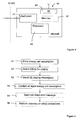
- FIG. 2 is an overview of a Long Term Evolution, LTE, Radio Access Network, RAN, and control plane, CP, core network consisting in this case of one eNodeB 12 with its connected Mobility Management Entity, MME 13, Operation and Support System, OSS 21, and using the S1 application protocol, S1-AP, interface for control signalling to the core network.
- MME 13 Mobility Management Entity
- OSS 21 Operation and Support System
- S1-AP S1 application protocol
- S1-AP S1 application protocol interface for control signalling to the core network.
- UEs 11 a-d there are four user equipments, UEs 11 a-d, in idle mode within one or more active cells of the radio access node 12, here represented as an eNodeB.
- the UEs 11 a-d are, from the MME 13 perspective, listed as last known to be present in said cells of the radio access node 12.
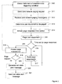
- Figure 3 discloses basic, representative, non-limiting flow chart including example steps which can be performed in an exemplary embodiment of the invention. Optional steps in the embodiment are depicted with dashed lines.
- the method steps are performed in a radio access node, e.g., an eNodeB 12, in a radio access network.
- the disclosed exemplary method is a method for performing sleepy cell test by paging one or more User Equipments, UEs, in a radio access network, e.g. the networks disclosed in Figure 1 or 2 .
- a predetermined triggering condition is detected, i.e., a condition indicating that one or more cells in the radio access network, RAN, suffers from loss of call processing.
- This state of is commonly denominated as “sleeping cell” or “sleepy cell”.
- the term “sleepy cell” will be used to describe a cell that cannot handle offered traffic in the area covered by the cell.
- a triggering mechanism such as an eNodeB internal cell supervision mechanism detects no incoming traffic on the Physical Random Access Channel, PRACH. Other triggering conditions and mechanisms for detecting these conditions are within the scope of the invention.
- the absence of traffic on the PRACH is just an exemplification of one possible triggering condition to initiate a sleepy cell test according to the disclosed embodiment of the invention.
- one or more user equipment, UE, to be paged in the cell with the suspected sleepy cell state is determined.
- the radio access node may send a paging request to the core network; in a preferred embodiment of the invention to the MME.
- the eNodeB awaits a response from the core network/MME and proceeds to step 313 following receipt of a core network paging message in step 312.
- the core network paging message is an ordinary paging message indicating one or more UEs to include in the paging. Selection of the UEs to page may be based on an MME internal selection algorithm.
- the MME UE selection mechanism may, for example, determine to page a certain percentage of the UEs last known to have been present in the cell or the eNodeB or it may start sequential paging of all UEs last known to have been present in the cell or eNodeB. Once the UEs have been selected a normal paging message is sent to the eNodeB.
- the paging request from the radio access node to the core network expresses a sleepy cell assumption for the cell fulfilling the triggering conditions for loss of call processing.
- a page response timer period is initiated in the radio access node.
- the page response timer period may be set in a supervision timer in the eNodeB.
- the eNodeB performs paging of the selected UEs by forwarding the received paging message on the paging channel, e.g., over the Physical Downlink Share Channel, PDSCH.
- the paging of user equipment is illustrated as a sequential step to the initiation of the page response timer period. However, it will be obvious to the person skilled in the art that these two steps are performed essentially simultaneously.
- the paging of selected UEs is performed in step 315 until the paged UEs have responded with service request or until the timer period has expired.
- the flow chart in Figure 3 illustrates the situation where paging is allowed to continue until the timer period expires or a page response is received in step 317 in the form of a page request from any of the paged UEs. If a page response in the form of a page request is received from any of the paged UEs, the test may be considered as completed even though the timer period has not yet expired. In the absence of a page response, the eNodeB performing the page will continue to await one or more page responses in step 317 from the UEs selected for the test procedure. In a power effective embodiment of the invention, the MME pages the selected UEs in a sequential way, limiting the number of pages and load on the eNodeB.
- step 318 an assessment of the page response(s) will be performed in step 318.
- the process of determining a cell state as illustrated in Figure 3 may be re-initiated at step 310 detecting fulfilment of predetermined triggering condition whilst performing the step of assessing page response(s) or following a a predetermined period of time.
- a message with a cell state alert will be generated in step 320 and sent to the OSS and/or the MME in step 321.
- the cell state alert message in step 320 may optionally be produced whereupon the self test is concluded.
- the procedure for self test will be re-initiated at step 310.
- a new S1-AP message could be initiated from the eNodeB toward the MME to mark the stop of the test.
- the supervision timer is not stopped when a page response in the form of a service request is received.
- the message to the MME is sent at time-out of the supervision timer and should include a result of the self test.
- the option of allowing time out of the timer period even upon receipt of a page response is indicated as an option in step 316.
- the message to the MME indicates that the MME may stop paging selected UEs
- the MME may initiate an additional S1-AP message toward the eNodeB if it has not received any page response from any of the UEs selected for paging. This additional S1-AP message will allow the radio access network to issue an alarm that the paging channel may suffer from an inability to process calls.
- FIG. 4 illustrates a radio access node 40 configured to initiate and/or participate in a cell state test for a cell served by the radio access node.
- the radio access node 40 comprises a communication unit NwComm 41 configured for communicating over the S1 interface with a core network entity, e.g., the MME.
- the radio access node 40 further comprises a radio transceiver 44 configured for forwarding of the paging messages to UEs in a cell, and receipt of page responses from one or more user equipment in a cell.
- a processor 43 in the radio access node 40 is configured to process test triggering information, to determine fulfillment of test triggering condition, to set a page response timer period, to assess user equipment page response and to generate a cell state alert message.
- the NwComm unit 41 is configured to transmit a cell state alert message to a receiving entity.
- the radio access node 40 may also comprise a memory 42 storing information on the UEs last present in the cells of the eNodeB. When the sleepy cell test is performed as a eNodeB test, the information in the memory 42 will be extracted to select the set of UEs to involve in the paging procedure.
- Figure 5 illustrates method steps of an embodiment of the invention in a radio access node.
- a sleepy cell assumption is formed in the radio access node.
- Such a sleepy cell assumption may be formed following fulfillment of a triggering condition for a suspected sleepy cell.
- the radio access node selects a set of UEs for paging during a sleepy cell test to evaluate the sleepy cell assumption.
- the UEs may be selected based on last known presence in the cell.
- the radio access node 12 may obtain information from the MME 13 of these UEs 11 a-d last present within cells of the node or in the suspected sleepy cell.
- the radio access node 12 may also obtain information from the MME 12 on a subset of one or more UEs last present in the MME to include in the paging procedure.
- step 53 a paging message for the selected set of UEs is sent from the radio access node handling the suspected sleepy cell.
- the radio access node 12 performs the paging and generates a cell state alert message as previously described for the embodiment according to Figure 3 .
- the radio access node 12 confirms or rejects 54 the sleepy cell assumption.
- a cell state alert message may optionally be sent 55 to an operation or support system or to a core network node.
- This cell state alert message may include information that a page request has been received and that the sleepy cell assumption is to be rejected, but the cell state alert message may also include information relating to the absence of a paging response from any of the UEs in the suspected sleepy cell, which may be interpreted as a confirmation that the sleepy cell assumption is correct.
- the cell state alert message is a S1-AP message.
- the embodiment of a method in a radio access node includes performing procedures for recovery of one or more cells for which the sleepy cell assumption has been confirmed.
- FIGS 6a-7b illustrate signaling sequences for sleepy cell tests performed in an exemplary LTE network, wherein the core network node is represented by a Mobility Management Entity, MME 13 and the radio access node is represented by an eNodeB 12.
- MME 13 could be substituted by core network entities performing the task of sending a paging message, similarly the eNodeBs 12 could be replace by other radio access nodes when the invention is embodied in other network configurations than an LTE network.
- a sleepy cell assumption 61 is formed in the eNodeB following fulfillment of a triggering condition in the eNodeB.
- the eNodeB 12 initiates the sleepy cell test by sending a paging request 62 to the MME 13. Signaling between the eNodeB 12 and the MME 13 is performed over the S1 interface by means of an S1 application protocol, S1-AP.
- the MME 13 selects 63 a set of UE 11 to involve in the sleepy cell test based on the UEs previous presence and activity in the cell for which the sleepy cell test is to be performed.
- the MME sends paging messages 64 toward each of these UEs in conventional manner.
- the paging messages may be sent in parallel, but may also be sent sequentially with an aim to save power and limit the load on the eNodeB.
- the eNodeB 12 receiving the paging messages 64 over the S1 interface forwards the paging messages to the respective UEs over the Physical Downlink Control Channel, PDCCH, as PDCCH Paging 65.
- a supervision timer is set in the eNodeB 12, to limit the supervision window for the sleepy cell test. In the disclosed signaling sequence, the supervision timer window is closed when the UE attach message 66 reaches the eNodeB 12.
- This page response from the UE may be forwarded from the eNodeB to the MME in the form of a service request 67 originated by the UE. Following receipt of the service request 67 in the MME, the sleepy cell assumption may be rejected 68 and the sleepy cell test is concluded.
- the signaling sequence in figure 6b discloses the same sleepy cell assumption 61 formed in the eNodeB 12 followed by a paging request 62 and a selection of UEs 63 as already disclosed for Figure 6a .
- the eNodeB 12 awaits a page response from the paged UEs.
- the supervision window closes on time-out 69 of the supervision timer whereupon the sleepy cell assumption is confirmed 611 in the eNodeB.
- the eNodeB 12 sends a cell state alert or alarm 613 to the OSS.
- a cell state alert 612 may also be sent to the MME 13 to conclude the sleepy cell test in the MME.
- the signaling sequence in Figure 7a discloses a sleepy cell test initiated and performed by the eNodeB 12 without specifically involving the MME 13, being useful for understanding the invention.
- the eNodeB 12 forms a sleepy cell assumption 71 following fulfillment of a triggering condition in the eNodeB.
- a memory in the eNodeB is configured to hold on UEs last present in the suspected sleepy cell handled by the eNodeB. Based on this information, the eNodeB 12 performs UE selection 72 and selects UEs 11 for paging.
- the eNodeB 12 initiates and sends an ordinary PDCCH paging message 73 to the set of UEs represented in said memory 42.
- the signaling sequence in Figure 7a discloses the situation with the sleepy cell assumption rejected 75 in the eNodeB following a page response in the form of UE attach 74 from one or more of the paged UEs in the suspected sleepy cell.
- the signaling sequence in Figure 7b discloses a sleepy cell test initiated and performed by the eNode as in Figure 7a including the sleepy cell assumption 71, the UE selection 72 and the PDCCH paging 73.
- the supervision window in the eNodeB closes without a page response from any of the paged UEs.
- the supervision window closes upon time-out 76 of a supervision timer set in the eNodeB at the time of the PDCCH paging signaling.
- the confirmation of the sleepy cell assumption is illustrated in the MME as sleepy cell assumption confirmed 77. This confirmation following time-out of the supervision timer, results in a cell state alert or alarm 79 to the operation and support system OSS 21.
- the eNodeB 12 may also, optionally, send a cell state alert 78 to the MME 13
- eNodeB has been used to represent a radio access node.
- the presentation of the signaling sequences for an eNodeB is non-limiting to the invention, and in the understanding of the invention an eNodeB should be interpreted as equivalent to a radio access node.
Description
- The present invention relates to a method in a radio access node for determining a cell state for a cell served by the radio access node. The invention also relates to a radio access node configured to perform the method.
- In a typical cellular radio system, wireless terminals communicate via a radio access network, RAN, to one or more core networks. The wireless terminals can be mobile stations or user equipment units, UE, such as portable, pocket, hand-held, computer-included, or car-mounted mobile devices which communicate voice and/or data with radio access network, e.g., mobile telephones and laptops with wireless capability.
- The RAN covers a geographical area which is divided into cell areas, with each cell area or group of cell areas being served by a radio access node. A cell is a geographical area where radio coverage is provided by equipment at the radio access node. Each cell is identified by an identity within the local radio area. The radio access nodes communicate over the air interface with the UE within the cells served by the node.
- The Universal Mobile Telecommunications System, UMTS, is a third generation mobile communication system, which evolved from the Global System for Mobile Communications, GSM, and is intended to provide improved mobile communication services based on Wideband Code Division Multiple Access , WCDMA, access technology. UTRAN is essentially a radio access network using wideband code division multiple access for user equipment units, UEs. The Third Generation Partnership Project, 3 GPP, has undertaken to evolve further the UTRAN and GSM based radio access network technologies. Specifications for the Evolved Universal Terrestrial Radio Access Network, E-UTRAN, are ongoing within the 3GPP. Another name used for E-UTRAN is the Long Term Evolution, LTE, Radio Access Network, RAN.
- Long Term Evolution RAN is a 3GPP radio access technology wherein a flat architecture is used with a singled type of nodes connected directly to a core network. The LTE RAN comprises evolved radio access nodes, e.g., evolved NodeBs or eNodeBs or eNBs, providing evolved UTRA user-plane and control-plane protocol terminations toward the user equipment. A common implementation of an eNodeB is a three-sector site, where the eNodeB includes equipment for handling transmissions in three cells. However, other implementations can be found as well. The eNodeB hosts functions for radio resource management, mobility management and user plane functions, among others. The eNodeB is connected to the core-network by means of the S1 interface.
- Within the LTE RAN there may be occurrences of cell outage, i.e., cells that due to hardware or software engineering faults suffer from loss of call processing. The lack of processing of traffic in a cell causes an inability in the node to process incoming calls or handle data for ongoing calls. A cell outage is a state when the cell cannot handle any of the offered traffic in the area covered by the cell. There are multiple reasons for a cell outage, e.g., hardware and software failures (radio board failure, channel processing implementation error etc), external failures such as power supply or network connectivity failures, or even erroneous configuration. When a cell is in an outage state, the cell cannot support any users in its vicinity. For the operators of wireless access networks this is an undesirable consequence as potential revenue is missed from the unsupported traffic and also customer satisfaction is damaged. It is important to be able to detect the state of cell outage promptly to be able mitigate the effect of the cell outage and to redirect the users to other cells within the radio access node or to other radio access nodes.
- A cell outage, i.e. one or more malfunctioning radio cells of a base station, e.g. a LTE eNB, may be detected by the base station associated with the affected radio cell by internal surveillance of processing boards and RF components of the base station. Some cell outage cases may also be detected by Operations Support System (OSS) functions through performance counters and/or alarms. By investigating a portion of the traffic related counters and their recent history, one can detect when a cell might have gone into a state of cell outage, a so called "Sleepy Cell". However, with the presently available solutions, detection of cell outage may be delayed for hours or even days. It is often through long term performance analysis and subscriber complaints that the outages are detected. Currently, discovery and identification of some errors may involve manual analysis and may require unplanned site visits, which makes cell outage detection a costly task. Patent Publication
WO 2011/157164 A1 describes a method for detecting a state of a cell in a radio network by broadcasting paging messages to all the user equipments. However, broadcasting the paging messages to all the user equipments makes cell outage detection a time consuming and a less effective task. 3GPP Draft "Potential Solution for self healing" describes potential solutions for Cell Outage Detection at RAN side. 3GPP Draft "Clarification of Self-healing at RAN" describes a method to detect and mitigate cell outage. - There is a need for improved solutions for determining a cell state in a radio access network.
- It is an object of an embodiment of the invention to provide improved solutions in a radio access network for evaluating and determining a state for a cell served by a radio access node.
- In accordance with a method embodiment of the invention, fulfilment of a predetermined triggering condition that indicates sleepy cell state of the cell served by the radio access node is detected in a radio access node in a first step of the embodiment. Following detection of the fulfilled triggering condition, one or more user equipment to be paged is determined. The radio access node initiates a page response timer period and performs paging of the user equipment until there is time out of the timer period or a page response is received from the one or more user equipment. The paging responses received whilst performing the step of paging the user equipment is assessed. When no page responses have been received, a cell state alert message reflecting this result from the paging is generated and sent to a receiving entity. The selection of user equipment to page as part of the cell state assessment in the radio access node may be determined by the radio access node itself, but may also in another embodiment of the invention be determined by a core network entity receiving a network paging request from the radio access node. The core network entity returns a paging message reflecting a set of user equipment to page that is received in the radio access node.
- An embodiment of a radio access node configured to carry out a cell state test for a cell served by the radio access node comprises a core network communication unit for exchange of messages with one or more core network entities. The radio access node further comprises a radio transceiver for sending paging messages and receiving page responses from one or more user equipment in a cell handled by the radio access node. A processor in the radio access node is configured to process test triggering information, that is, information used to evaluate fulfillment of a predetermined triggering condition that indicates sleepy cell state of the cell served by the radio access node. The processor is further configured to set a page response timer period for performing a paging procedure as part of the cell state test. The processor is configured to perform assessment of the user equipment page response and to generate a cell state alert message. The radio transceiver is further configured for sending a core network paging request to the core network entity and receiving a core network paging message from the core network entity.
- Embodiments of the invention are advantageous for evaluating and determining the state for a cell served by a radio access node. The disclosed technology provides a simple and effective way to conclude sleepy cell state, providing a more accurate understanding of current cell state and shortening the time to trigger an accurate alarm when there is a cell outage. Embodiments of the invention contribute to faster recovery from the sleepy cell state.
-
-
Figure 1 is a schematic view of an exemplary Long Term Evolution, LTE, network -
Figure 2 is a schematic view of a LTE RAN and control plane core network -
Figure 3 is a flow chart illustrating an embodiment of method steps in a radio access node -
Figure 4 is a block diagram of a radio access node according to an embodiment of the invention -
Figure 5 is a flow chart illustrating an embodiment of method steps in a core network node -
Figure 6 signaling diagrams for sleepy cell tests involving core network entities- a. is a signaling diagram illustrating a sleepy cell test where the sleepy cell assumption is rejected
- b. is a signaling diagram illustrating a sleepy cell test where the sleepy cell assumption is confirmed
-
Figure 7 signaling diagrams for sleepy cell tests involving an access node entity- a. is a signaling diagram illustrating a sleepy cell test where the sleepy cell assumption is rejected
- b. is a signaling diagram illustrating a sleepy cell test where the sleepy cell assumption is confirmed
-
Figure 1 shows a schematic view of an exemplary E-UTRAN/LTE network 10, wherein the invention may be implemented. AneNodeB 12 is connected to a Serving Gateway, S-GW, and theMobility Management Entity 13, MME, by means of the S1 interface. eNodeBs 12a, b c are connected to one another over the X2 interface. The following detailed description of the invention in a LTE network is merely an exemplification of a network suitable for carrying out the invention, but is non-limiting to the invention. The invention may be performed in any other type of network configuration involving call processing in cells handled by radio access nodes, wherein a loss of call processing capability may occur. -
Figure 2 is an overview of a Long Term Evolution, LTE, Radio Access Network, RAN, and control plane, CP, core network consisting in this case of oneeNodeB 12 with its connected Mobility Management Entity,MME 13, Operation and Support System,OSS 21, and using the S1 application protocol, S1-AP, interface for control signalling to the core network. In the disclosed situation, there are four user equipments,UEs 11 a-d, in idle mode within one or more active cells of theradio access node 12, here represented as an eNodeB. TheUEs 11 a-d are, from theMME 13 perspective, listed as last known to be present in said cells of theradio access node 12. -
Figure 3 discloses basic, representative, non-limiting flow chart including example steps which can be performed in an exemplary embodiment of the invention. Optional steps in the embodiment are depicted with dashed lines. The method steps are performed in a radio access node, e.g., aneNodeB 12, in a radio access network. The disclosed exemplary method is a method for performing sleepy cell test by paging one or more User Equipments, UEs, in a radio access network, e.g. the networks disclosed inFigure 1 or 2 . - In a first step,
step 310, a predetermined triggering condition is detected, i.e., a condition indicating that one or more cells in the radio access network, RAN, suffers from loss of call processing. This state of is commonly denominated as "sleeping cell" or "sleepy cell". In the following, the term "sleepy cell" will be used to describe a cell that cannot handle offered traffic in the area covered by the cell. A triggering mechanism such as an eNodeB internal cell supervision mechanism detects no incoming traffic on the Physical Random Access Channel, PRACH. Other triggering conditions and mechanisms for detecting these conditions are within the scope of the invention. The absence of traffic on the PRACH is just an exemplification of one possible triggering condition to initiate a sleepy cell test according to the disclosed embodiment of the invention. - In a succeeding
step 313, one or more user equipment, UE, to be paged in the cell with the suspected sleepy cell state is determined. Instep 311, precedingstep 313, the radio access node may send a paging request to the core network; in a preferred embodiment of the invention to the MME. Following the paging request, the eNodeB awaits a response from the core network/MME and proceeds to step 313 following receipt of a core network paging message instep 312. The core network paging message is an ordinary paging message indicating one or more UEs to include in the paging. Selection of the UEs to page may be based on an MME internal selection algorithm. The MME UE selection mechanism may, for example, determine to page a certain percentage of the UEs last known to have been present in the cell or the eNodeB or it may start sequential paging of all UEs last known to have been present in the cell or eNodeB. Once the UEs have been selected a normal paging message is sent to the eNodeB. The paging request from the radio access node to the core network expresses a sleepy cell assumption for the cell fulfilling the triggering conditions for loss of call processing. - In a
step 314, a page response timer period is initiated in the radio access node. The page response timer period may be set in a supervision timer in the eNodeB. The eNodeB performs paging of the selected UEs by forwarding the received paging message on the paging channel, e.g., over the Physical Downlink Share Channel, PDSCH. In the disclosed flow chart inFigure 3 , the paging of user equipment is illustrated as a sequential step to the initiation of the page response timer period. However, it will be obvious to the person skilled in the art that these two steps are performed essentially simultaneously. - The paging of selected UEs is performed in
step 315 until the paged UEs have responded with service request or until the timer period has expired. The flow chart inFigure 3 illustrates the situation where paging is allowed to continue until the timer period expires or a page response is received instep 317 in the form of a page request from any of the paged UEs. If a page response in the form of a page request is received from any of the paged UEs, the test may be considered as completed even though the timer period has not yet expired. In the absence of a page response, the eNodeB performing the page will continue to await one or more page responses instep 317 from the UEs selected for the test procedure. In a power effective embodiment of the invention, the MME pages the selected UEs in a sequential way, limiting the number of pages and load on the eNodeB. - Following time out of the supervision timer or a page response in
step 316, an assessment of the page response(s) will be performed instep 318. Optionally, the process of determining a cell state as illustrated inFigure 3 may be re-initiated atstep 310 detecting fulfilment of predetermined triggering condition whilst performing the step of assessing page response(s) or following a a predetermined period of time. Upon confirmation that no page responses has been receivedinstep 319, a message with a cell state alert will be generated instep 320 and sent to the OSS and/or the MME instep 321. When it is determined that a page response is received instep 319, the cell state alert message instep 320 may optionally be produced whereupon the self test is concluded. However, following UE attach based on sent paging messages, the procedure for self test will be re-initiated atstep 310. A new S1-AP message could be initiated from the eNodeB toward the MME to mark the stop of the test. In a preferred embodiment of the invention, the supervision timer is not stopped when a page response in the form of a service request is received. The message to the MME is sent at time-out of the supervision timer and should include a result of the self test. InFigure 3 , the option of allowing time out of the timer period even upon receipt of a page response is indicated as an option instep 316. The message to the MME indicates that the MME may stop paging selected UEs - If the MME receives a cell state alert message, as illustrated in
step 321, that marks the stop of the self test and the message includes a result that indicates that the cell is healthy, the MME may initiate an additional S1-AP message toward the eNodeB if it has not received any page response from any of the UEs selected for paging. This additional S1-AP message will allow the radio access network to issue an alarm that the paging channel may suffer from an inability to process calls. -
Figure 4 illustrates aradio access node 40 configured to initiate and/or participate in a cell state test for a cell served by the radio access node. Theradio access node 40 comprises acommunication unit NwComm 41 configured for communicating over the S1 interface with a core network entity, e.g., the MME. Theradio access node 40 further comprises aradio transceiver 44 configured for forwarding of the paging messages to UEs in a cell, and receipt of page responses from one or more user equipment in a cell. Aprocessor 43 in theradio access node 40 is configured to process test triggering information, to determine fulfillment of test triggering condition, to set a page response timer period, to assess user equipment page response and to generate a cell state alert message. TheNwComm unit 41 is configured to transmit a cell state alert message to a receiving entity. Theradio access node 40 may also comprise amemory 42 storing information on the UEs last present in the cells of the eNodeB. When the sleepy cell test is performed as a eNodeB test, the information in thememory 42 will be extracted to select the set of UEs to involve in the paging procedure. -
Figure 5 illustrates method steps of an embodiment of the invention in a radio access node. In afirst step 51, a sleepy cell assumption is formed in the radio access node. Such a sleepy cell assumption may be formed following fulfillment of a triggering condition for a suspected sleepy cell. - In a
subsequent step 52, the radio access node selects a set of UEs for paging during a sleepy cell test to evaluate the sleepy cell assumption. The UEs may be selected based on last known presence in the cell. Applying the method to the network configuration ofFigure 2 , there are fourUEs 11 a-d in RRC _IDLE state. TheseUEs 11a-d are from the MME perspective listed as last known to be present in the radio access node, here represented aseNodeB 12. Theradio access node 12 may obtain information from theMME 13 of theseUEs 11 a-d last present within cells of the node or in the suspected sleepy cell. Theradio access node 12 may also obtain information from theMME 12 on a subset of one or more UEs last present in the MME to include in the paging procedure. - In step 53 a paging message for the selected set of UEs is sent from the radio access node handling the suspected sleepy cell. The
radio access node 12 performs the paging and generates a cell state alert message as previously described for the embodiment according toFigure 3 . - When the
radio access nodes 12 role in the sleepy cell paging procedure is concluded, theradio access node 12 confirms or rejects 54 the sleepy cell assumption. A cell state alert message may optionally be sent 55 to an operation or support system or to a core network node. This cell state alert message may include information that a page request has been received and that the sleepy cell assumption is to be rejected, but the cell state alert message may also include information relating to the absence of a paging response from any of the UEs in the suspected sleepy cell, which may be interpreted as a confirmation that the sleepy cell assumption is correct. In a preferred embodiment of the invention, the cell state alert message is a S1-AP message. - In yet an
optional step 56 the embodiment of a method in a radio access node includes performing procedures for recovery of one or more cells for which the sleepy cell assumption has been confirmed. -
Figures 6a-7b illustrate signaling sequences for sleepy cell tests performed in an exemplary LTE network, wherein the core network node is represented by a Mobility Management Entity,MME 13 and the radio access node is represented by aneNodeB 12. TheMME 13 could be substituted by core network entities performing the task of sending a paging message, similarly theeNodeBs 12 could be replace by other radio access nodes when the invention is embodied in other network configurations than an LTE network. - In
Figure 6a , asleepy cell assumption 61 is formed in the eNodeB following fulfillment of a triggering condition in the eNodeB. TheeNodeB 12 initiates the sleepy cell test by sending apaging request 62 to theMME 13. Signaling between theeNodeB 12 and theMME 13 is performed over the S1 interface by means of an S1 application protocol, S1-AP. TheMME 13 selects 63 a set ofUE 11 to involve in the sleepy cell test based on the UEs previous presence and activity in the cell for which the sleepy cell test is to be performed. The MME sendspaging messages 64 toward each of these UEs in conventional manner. The paging messages may be sent in parallel, but may also be sent sequentially with an aim to save power and limit the load on the eNodeB. TheeNodeB 12 receiving thepaging messages 64 over the S1 interface, forwards the paging messages to the respective UEs over the Physical Downlink Control Channel, PDCCH, asPDCCH Paging 65. A supervision timer is set in theeNodeB 12, to limit the supervision window for the sleepy cell test. In the disclosed signaling sequence, the supervision timer window is closed when the UE attachmessage 66 reaches theeNodeB 12. This page response from the UE, may be forwarded from the eNodeB to the MME in the form of aservice request 67 originated by the UE. Following receipt of theservice request 67 in the MME, the sleepy cell assumption may be rejected 68 and the sleepy cell test is concluded. - The signaling sequence in
figure 6b , discloses the samesleepy cell assumption 61 formed in theeNodeB 12 followed by apaging request 62 and a selection ofUEs 63 as already disclosed forFigure 6a . Following thepaging message 64 from theMME 13 to theeNodeB 12 and thePDCCH paging 65, theeNodeB 12 awaits a page response from the paged UEs. The supervision window closes on time-out 69 of the supervision timer whereupon the sleepy cell assumption is confirmed 611 in the eNodeB. TheeNodeB 12 sends a cell state alert oralarm 613 to the OSS. As an option, acell state alert 612 may also be sent to theMME 13 to conclude the sleepy cell test in the MME. - The signaling sequence in
Figure 7a , discloses a sleepy cell test initiated and performed by theeNodeB 12 without specifically involving theMME 13, being useful for understanding the invention. TheeNodeB 12 forms asleepy cell assumption 71 following fulfillment of a triggering condition in the eNodeB. A memory in the eNodeB is configured to hold on UEs last present in the suspected sleepy cell handled by the eNodeB. Based on this information, theeNodeB 12 performsUE selection 72 and selectsUEs 11 for paging. TheeNodeB 12 initiates and sends an ordinaryPDCCH paging message 73 to the set of UEs represented in saidmemory 42. The signaling sequence inFigure 7a , discloses the situation with the sleepy cell assumption rejected 75 in the eNodeB following a page response in the form of UE attach 74 from one or more of the paged UEs in the suspected sleepy cell. - The signaling sequence in
Figure 7b , discloses a sleepy cell test initiated and performed by the eNode as inFigure 7a including thesleepy cell assumption 71, theUE selection 72 and thePDCCH paging 73. In the disclosed signaling sequence being useful for understanding the invention, the supervision window in the eNodeB closes without a page response from any of the paged UEs. The supervision window closes upon time-out 76 of a supervision timer set in the eNodeB at the time of the PDCCH paging signaling. The confirmation of the sleepy cell assumption is illustrated in the MME as sleepy cell assumption confirmed 77. This confirmation following time-out of the supervision timer, results in a cell state alert oralarm 79 to the operation andsupport system OSS 21. TheeNodeB 12 may also, optionally, send acell state alert 78 to theMME 13 - In the disclosed signaling diagrams, the term eNodeB has been used to represent a radio access node. The presentation of the signaling sequences for an eNodeB is non-limiting to the invention, and in the understanding of the invention an eNodeB should be interpreted as equivalent to a radio access node.
Claims (13)
- A method in a radio access node in a radio access network for determining a cell state for a cell served by the radio access node, including the steps of:- detecting (310) fulfillment of a predetermined triggering condition that indicates sleepy cell state of the cell served by the radio access node;- determining (313) one or more user equipment to be paged in the cell;- initiating (314) a predetermined page response timer period;- paging (315) the one or more user equipment;- awaiting (317) user equipment page response(s) during the predetermined page response timer period; and- at time out (316) of the predetermined page response timer period, assessing (318) the user equipment page response(s) originated in the cell to generate (320) a cell state alert message when not receiving a page response(s) (319); and sending (321) the cell state alert message to a receiving entity;characterized in that, the method further comprises following the detected fulfillment of predetermined triggering condition to perform the steps of:- sending (311) a core network paging request to a core network entity; and- receiving a (312) core network paging message from the core network entity.
- A method according to claim 1, further involving repeating the method from the step of detecting (310) fulfillment of predetermined triggering condition.
- A method according to claim 2, wherein the repeating is performed a predetermined period of time following conclusion of the step of assessing (318) page response(s).
- A method according to claim 1-3, wherein the receiving entity is the Operation and Support System, OSS.
- A method according to claim 1 -3, wherein the receiving entity is the core network entity.
- A method according to claim 1, wherein the user equipment to be paged is determined from information included in the S1-AP paging message.
- A method according to any of the preceding claims, simultaneously being performed for all cells served by the radio access node.
- A method according to any of the preceding claims, wherein the user equipment page response is a service request.
- A method according to any of the preceding claims, wherein the cell state alert message is generated and sent for any result from the step of assessing the user equipment page response(s).
- A method according to claim 1, further comprising the steps of:- forming (51) a sleepy cell assumption; and- rejecting (54) the sleepy cell assumption on receipt of a user equipment paging response; or- confirming (54) the sleepy cell assumption at time out of the predetermined page response timer period.
- A method according to claim 10, further including the step of: performing one or more predetermined procedures for recovery from a sleepy cell state.
- A radio access node (40) configured to initiate a cell state test for a cell served by the radio access node, the radio access node (40) comprising:- a core network communication unit (41) configured for messaging with one or more core network entities;- a radio transceiver (44) configured for paging and receipt of page responses from one or more user equipment in a cell; and- a processor (43) configured to process test triggering information that indicates sleepy cell state of the cell served by the radio access node, to determine fulfillment of test triggering condition, to set a page response timer period, to assess user equipment page response and to generate a cell state alert message;characterized in that, the radio transceiver (44) being further configured for following the detected fulfillment of test triggering condition to perform the steps of:- sending a core network paging request to the core network entity; and- receiving a core network paging message from the core network entity.
- A radio access node (40) according to claim 12 further comprising: a memory (42) configured to store information on a number of user equipment last known to be present in a cell served by the radio access node.
Applications Claiming Priority (1)
| Application Number | Priority Date | Filing Date | Title |
|---|---|---|---|
| PCT/SE2012/050677 WO2013191600A1 (en) | 2012-06-19 | 2012-06-19 | Methods and radio access node for determining a cell state |
Publications (3)
| Publication Number | Publication Date |
|---|---|
| EP2862386A1 EP2862386A1 (en) | 2015-04-22 |
| EP2862386A4 EP2862386A4 (en) | 2015-06-24 |
| EP2862386B1 true EP2862386B1 (en) | 2016-01-13 |
Family
ID=49769089
Family Applications (1)
| Application Number | Title | Priority Date | Filing Date |
|---|---|---|---|
| EP12879540.8A Active EP2862386B1 (en) | 2012-06-19 | 2012-06-19 | Methods and radio access node for determining a cell state |
Country Status (3)
| Country | Link |
|---|---|
| US (1) | US9756513B2 (en) |
| EP (1) | EP2862386B1 (en) |
| WO (1) | WO2013191600A1 (en) |
Families Citing this family (5)
| Publication number | Priority date | Publication date | Assignee | Title |
|---|---|---|---|---|
| US9578524B2 (en) * | 2012-09-07 | 2017-02-21 | Telefonaktiebolaget Lm Ericsson (Publ) | Method, device and program for validation of sleeping cells in a communications network |
| US10517136B1 (en) | 2016-10-28 | 2019-12-24 | Sprint Communications Company L.P. | Wireless communication system to detect a sleepy-cell condition |
| WO2020031263A1 (en) * | 2018-08-07 | 2020-02-13 | 株式会社Nttドコモ | Radio node and radio communication method |
| WO2020064094A1 (en) * | 2018-09-26 | 2020-04-02 | Telefonaktiebolaget Lm Ericsson (Publ) | Method and system for predicting a state of a cell in a radio access network |
| US11039494B2 (en) * | 2019-08-12 | 2021-06-15 | T-Mobile Usa, Inc. | Base station sleeping cell recovery |
Family Cites Families (13)
| Publication number | Priority date | Publication date | Assignee | Title |
|---|---|---|---|---|
| ATE549881T1 (en) | 2008-05-28 | 2012-03-15 | Alcatel Lucent | METHOD FOR DETECTING RADIO CELL FAILURE |
| WO2010049119A1 (en) * | 2008-10-27 | 2010-05-06 | Nec Europe Ltd. | Method for operating a wimax femtocell base station and femtocell base station |
| US8095075B2 (en) * | 2009-03-10 | 2012-01-10 | Telefonaktiebolaget Lm Ericsson (Publ) | System and method of detecting a sleeping cell and remedying detected conditions in a telecommunication network |
| CN101873677B (en) * | 2009-04-23 | 2016-09-28 | 中兴通讯股份有限公司 | The control method of carrier power and device |
| US8750856B2 (en) * | 2009-08-13 | 2014-06-10 | Alcatel Lucent | Distributed sleeping cell detection |
| KR101661252B1 (en) * | 2010-04-29 | 2016-10-10 | 인터디지탈 패튼 홀딩스, 인크 | Using personal wireless devices for network testing |
| CN102281555B (en) * | 2010-06-13 | 2016-03-09 | 华为技术有限公司 | The method of cell detection, Apparatus and system |
| US8520634B2 (en) * | 2010-08-04 | 2013-08-27 | Sierra Wireless, Inc. | Active/standby operation of a femtocell base station |
| EP2432284B1 (en) * | 2010-09-21 | 2019-03-20 | Provenance Asset Group LLC | A macrocell base station, a telecommunications network, and a femtocell base station, and a method of switching a femtocell base station between a dormant mode and an active mode |
| EP2512171B1 (en) * | 2011-04-14 | 2014-08-13 | Alcatel Lucent | Method for managing the state of micro base stations by following the variations of traffic requirements, and associated controller device |
| US9204315B2 (en) * | 2011-06-20 | 2015-12-01 | Alcatel Lucent | Method of coordinating fault detection responses by access nodes of a network |
| US20130036428A1 (en) * | 2011-08-02 | 2013-02-07 | Yu-Hsiang Lei | Event triggering method during sleep mode and related mobile devices |
| KR101579030B1 (en) * | 2012-04-05 | 2015-12-18 | 옵티스 셀룰러 테크놀로지, 엘엘씨 | Advanced Wakeup for Reception of Paging Configuration Information |
-
2012
- 2012-06-19 US US14/408,252 patent/US9756513B2/en active Active
- 2012-06-19 EP EP12879540.8A patent/EP2862386B1/en active Active
- 2012-06-19 WO PCT/SE2012/050677 patent/WO2013191600A1/en active Application Filing
Also Published As
| Publication number | Publication date |
|---|---|
| WO2013191600A1 (en) | 2013-12-27 |
| EP2862386A4 (en) | 2015-06-24 |
| US9756513B2 (en) | 2017-09-05 |
| US20150181446A1 (en) | 2015-06-25 |
| EP2862386A1 (en) | 2015-04-22 |
Similar Documents
| Publication | Publication Date | Title |
|---|---|---|
| US10986546B2 (en) | Method, apparatus, and system for detecting a radio network problem | |
| US9723647B2 (en) | Handling a radio link failure in communications | |
| US8095075B2 (en) | System and method of detecting a sleeping cell and remedying detected conditions in a telecommunication network | |
| US9167447B2 (en) | Failure event report for initial connection setup failure | |
| US10178563B2 (en) | Method and apparatus for processing fault in multi-operator core network | |
| US20200374950A1 (en) | Method, Telecommunications Node and Telecommunications Terminal | |
| WO2013141660A1 (en) | Method and apparatus for accessing cell in wireless communication system | |
| KR20120104959A (en) | Handling reachability of mobile device when serving core network node changes | |
| US9445330B2 (en) | Pre-configured redirection information | |
| US20130083667A1 (en) | Accessibility Measurements | |
| US10728785B2 (en) | Radio communication device and method of mobile radio cell measurement reporting | |
| EP2862386B1 (en) | Methods and radio access node for determining a cell state | |
| CN113455027B (en) | Method and apparatus for mobile roaming service | |
| WO2020250548A1 (en) | Method and apparatus for reporting multi-usim ue capability in 5g nr system | |
| EP3205169A1 (en) | Connection establishment robustness optimization | |
| EP3738246B1 (en) | Radio link maintenance involving muliple uplink carriers | |
| EP2562982A1 (en) | Method and system for radio link failure information processing | |
| MX2011003305A (en) | Method for operating a closed subscriber group (csg) cell for open network access. | |
| US20220361058A1 (en) | Method and apparatus for performing handover of a multi-usim radio-capable ue over same or different systems | |
| WO2021002268A1 (en) | Method and apparatus for reporting multi-usim ue capability supporting different operators | |
| CN111919463B (en) | Method and apparatus for call setup failure control | |
| WO2013051984A1 (en) | Accessibility measurements |
Legal Events
| Date | Code | Title | Description |
|---|---|---|---|
| PUAI | Public reference made under article 153(3) epc to a published international application that has entered the european phase |
Free format text: ORIGINAL CODE: 0009012 |
|
| 17P | Request for examination filed |
Effective date: 20141117 |
|
| AK | Designated contracting states |
Kind code of ref document: A1 Designated state(s): AL AT BE BG CH CY CZ DE DK EE ES FI FR GB GR HR HU IE IS IT LI LT LU LV MC MK MT NL NO PL PT RO RS SE SI SK SM TR |
|
| AX | Request for extension of the european patent |
Extension state: BA ME |
|
| RA4 | Supplementary search report drawn up and despatched (corrected) |
Effective date: 20150521 |
|
| RIC1 | Information provided on ipc code assigned before grant |
Ipc: H04W 88/08 20090101ALN20150515BHEP Ipc: H04W 24/08 20090101ALI20150515BHEP Ipc: H04W 68/00 20090101ALN20150515BHEP Ipc: H04W 24/04 20090101AFI20150515BHEP |
|
| 17Q | First examination report despatched |
Effective date: 20150615 |
|
| DAX | Request for extension of the european patent (deleted) | ||
| REG | Reference to a national code |
Ref country code: DE Ref legal event code: R079 Ref document number: 602012014021 Country of ref document: DE Free format text: PREVIOUS MAIN CLASS: H04W0028040000 Ipc: H04W0024040000 |
|
| GRAP | Despatch of communication of intention to grant a patent |
Free format text: ORIGINAL CODE: EPIDOSNIGR1 |
|
| GRAS | Grant fee paid |
Free format text: ORIGINAL CODE: EPIDOSNIGR3 |
|
| RIC1 | Information provided on ipc code assigned before grant |
Ipc: H04W 24/06 20090101ALI20151016BHEP Ipc: H04W 88/08 20090101ALN20151016BHEP Ipc: H04W 68/00 20090101ALN20151016BHEP Ipc: H04W 52/02 20090101ALI20151016BHEP Ipc: H04W 24/04 20090101AFI20151016BHEP Ipc: H04W 24/08 20090101ALI20151016BHEP |
|
| INTG | Intention to grant announced |
Effective date: 20151103 |
|
| GRAA | (expected) grant |
Free format text: ORIGINAL CODE: 0009210 |
|
| AK | Designated contracting states |
Kind code of ref document: B1 Designated state(s): AL AT BE BG CH CY CZ DE DK EE ES FI FR GB GR HR HU IE IS IT LI LT LU LV MC MK MT NL NO PL PT RO RS SE SI SK SM TR |
|
| REG | Reference to a national code |
Ref country code: GB Ref legal event code: FG4D |
|
| REG | Reference to a national code |
Ref country code: CH Ref legal event code: EP |
|
| REG | Reference to a national code |
Ref country code: IE Ref legal event code: FG4D |
|
| REG | Reference to a national code |
Ref country code: AT Ref legal event code: REF Ref document number: 771214 Country of ref document: AT Kind code of ref document: T Effective date: 20160215 |
|
| REG | Reference to a national code |
Ref country code: DE Ref legal event code: R096 Ref document number: 602012014021 Country of ref document: DE |
|
| REG | Reference to a national code |
Ref country code: LT Ref legal event code: MG4D |
|
| REG | Reference to a national code |
Ref country code: NL Ref legal event code: MP Effective date: 20160113 |
|
| REG | Reference to a national code |
Ref country code: AT Ref legal event code: MK05 Ref document number: 771214 Country of ref document: AT Kind code of ref document: T Effective date: 20160113 |
|
| REG | Reference to a national code |
Ref country code: FR Ref legal event code: PLFP Year of fee payment: 5 |
|
| PG25 | Lapsed in a contracting state [announced via postgrant information from national office to epo] |
Ref country code: NL Free format text: LAPSE BECAUSE OF FAILURE TO SUBMIT A TRANSLATION OF THE DESCRIPTION OR TO PAY THE FEE WITHIN THE PRESCRIBED TIME-LIMIT Effective date: 20160113 |
|
| PG25 | Lapsed in a contracting state [announced via postgrant information from national office to epo] |
Ref country code: GR Free format text: LAPSE BECAUSE OF FAILURE TO SUBMIT A TRANSLATION OF THE DESCRIPTION OR TO PAY THE FEE WITHIN THE PRESCRIBED TIME-LIMIT Effective date: 20160414 Ref country code: NO Free format text: LAPSE BECAUSE OF FAILURE TO SUBMIT A TRANSLATION OF THE DESCRIPTION OR TO PAY THE FEE WITHIN THE PRESCRIBED TIME-LIMIT Effective date: 20160413 Ref country code: ES Free format text: LAPSE BECAUSE OF FAILURE TO SUBMIT A TRANSLATION OF THE DESCRIPTION OR TO PAY THE FEE WITHIN THE PRESCRIBED TIME-LIMIT Effective date: 20160113 Ref country code: HR Free format text: LAPSE BECAUSE OF FAILURE TO SUBMIT A TRANSLATION OF THE DESCRIPTION OR TO PAY THE FEE WITHIN THE PRESCRIBED TIME-LIMIT Effective date: 20160113 Ref country code: IT Free format text: LAPSE BECAUSE OF FAILURE TO SUBMIT A TRANSLATION OF THE DESCRIPTION OR TO PAY THE FEE WITHIN THE PRESCRIBED TIME-LIMIT Effective date: 20160113 Ref country code: FI Free format text: LAPSE BECAUSE OF FAILURE TO SUBMIT A TRANSLATION OF THE DESCRIPTION OR TO PAY THE FEE WITHIN THE PRESCRIBED TIME-LIMIT Effective date: 20160113 |
|
| PG25 | Lapsed in a contracting state [announced via postgrant information from national office to epo] |
Ref country code: LV Free format text: LAPSE BECAUSE OF FAILURE TO SUBMIT A TRANSLATION OF THE DESCRIPTION OR TO PAY THE FEE WITHIN THE PRESCRIBED TIME-LIMIT Effective date: 20160113 Ref country code: PL Free format text: LAPSE BECAUSE OF FAILURE TO SUBMIT A TRANSLATION OF THE DESCRIPTION OR TO PAY THE FEE WITHIN THE PRESCRIBED TIME-LIMIT Effective date: 20160113 Ref country code: SE Free format text: LAPSE BECAUSE OF FAILURE TO SUBMIT A TRANSLATION OF THE DESCRIPTION OR TO PAY THE FEE WITHIN THE PRESCRIBED TIME-LIMIT Effective date: 20160113 Ref country code: RS Free format text: LAPSE BECAUSE OF FAILURE TO SUBMIT A TRANSLATION OF THE DESCRIPTION OR TO PAY THE FEE WITHIN THE PRESCRIBED TIME-LIMIT Effective date: 20160113 Ref country code: PT Free format text: LAPSE BECAUSE OF FAILURE TO SUBMIT A TRANSLATION OF THE DESCRIPTION OR TO PAY THE FEE WITHIN THE PRESCRIBED TIME-LIMIT Effective date: 20160513 Ref country code: AT Free format text: LAPSE BECAUSE OF FAILURE TO SUBMIT A TRANSLATION OF THE DESCRIPTION OR TO PAY THE FEE WITHIN THE PRESCRIBED TIME-LIMIT Effective date: 20160113 Ref country code: LT Free format text: LAPSE BECAUSE OF FAILURE TO SUBMIT A TRANSLATION OF THE DESCRIPTION OR TO PAY THE FEE WITHIN THE PRESCRIBED TIME-LIMIT Effective date: 20160113 Ref country code: IS Free format text: LAPSE BECAUSE OF FAILURE TO SUBMIT A TRANSLATION OF THE DESCRIPTION OR TO PAY THE FEE WITHIN THE PRESCRIBED TIME-LIMIT Effective date: 20160513 |
|
| PGFP | Annual fee paid to national office [announced via postgrant information from national office to epo] |
Ref country code: FR Payment date: 20160628 Year of fee payment: 5 |
|
| REG | Reference to a national code |
Ref country code: DE Ref legal event code: R097 Ref document number: 602012014021 Country of ref document: DE |
|
| PG25 | Lapsed in a contracting state [announced via postgrant information from national office to epo] |
Ref country code: EE Free format text: LAPSE BECAUSE OF FAILURE TO SUBMIT A TRANSLATION OF THE DESCRIPTION OR TO PAY THE FEE WITHIN THE PRESCRIBED TIME-LIMIT Effective date: 20160113 Ref country code: DK Free format text: LAPSE BECAUSE OF FAILURE TO SUBMIT A TRANSLATION OF THE DESCRIPTION OR TO PAY THE FEE WITHIN THE PRESCRIBED TIME-LIMIT Effective date: 20160113 |
|
| PLBE | No opposition filed within time limit |
Free format text: ORIGINAL CODE: 0009261 |
|
| STAA | Information on the status of an ep patent application or granted ep patent |
Free format text: STATUS: NO OPPOSITION FILED WITHIN TIME LIMIT |
|
| PG25 | Lapsed in a contracting state [announced via postgrant information from national office to epo] |
Ref country code: CZ Free format text: LAPSE BECAUSE OF FAILURE TO SUBMIT A TRANSLATION OF THE DESCRIPTION OR TO PAY THE FEE WITHIN THE PRESCRIBED TIME-LIMIT Effective date: 20160113 Ref country code: SK Free format text: LAPSE BECAUSE OF FAILURE TO SUBMIT A TRANSLATION OF THE DESCRIPTION OR TO PAY THE FEE WITHIN THE PRESCRIBED TIME-LIMIT Effective date: 20160113 Ref country code: RO Free format text: LAPSE BECAUSE OF FAILURE TO SUBMIT A TRANSLATION OF THE DESCRIPTION OR TO PAY THE FEE WITHIN THE PRESCRIBED TIME-LIMIT Effective date: 20160113 Ref country code: SM Free format text: LAPSE BECAUSE OF FAILURE TO SUBMIT A TRANSLATION OF THE DESCRIPTION OR TO PAY THE FEE WITHIN THE PRESCRIBED TIME-LIMIT Effective date: 20160113 |
|
| 26N | No opposition filed |
Effective date: 20161014 |
|
| PG25 | Lapsed in a contracting state [announced via postgrant information from national office to epo] |
Ref country code: BE Free format text: LAPSE BECAUSE OF FAILURE TO SUBMIT A TRANSLATION OF THE DESCRIPTION OR TO PAY THE FEE WITHIN THE PRESCRIBED TIME-LIMIT Effective date: 20160113 |
|
| PG25 | Lapsed in a contracting state [announced via postgrant information from national office to epo] |
Ref country code: MC Free format text: LAPSE BECAUSE OF FAILURE TO SUBMIT A TRANSLATION OF THE DESCRIPTION OR TO PAY THE FEE WITHIN THE PRESCRIBED TIME-LIMIT Effective date: 20160113 |
|
| REG | Reference to a national code |
Ref country code: CH Ref legal event code: PL |
|
| PG25 | Lapsed in a contracting state [announced via postgrant information from national office to epo] |
Ref country code: SI Free format text: LAPSE BECAUSE OF FAILURE TO SUBMIT A TRANSLATION OF THE DESCRIPTION OR TO PAY THE FEE WITHIN THE PRESCRIBED TIME-LIMIT Effective date: 20160113 Ref country code: BG Free format text: LAPSE BECAUSE OF FAILURE TO SUBMIT A TRANSLATION OF THE DESCRIPTION OR TO PAY THE FEE WITHIN THE PRESCRIBED TIME-LIMIT Effective date: 20160413 |
|
| REG | Reference to a national code |
Ref country code: IE Ref legal event code: MM4A |
|
| PG25 | Lapsed in a contracting state [announced via postgrant information from national office to epo] |
Ref country code: LI Free format text: LAPSE BECAUSE OF NON-PAYMENT OF DUE FEES Effective date: 20160630 Ref country code: CH Free format text: LAPSE BECAUSE OF NON-PAYMENT OF DUE FEES Effective date: 20160630 |
|
| PG25 | Lapsed in a contracting state [announced via postgrant information from national office to epo] |
Ref country code: IE Free format text: LAPSE BECAUSE OF NON-PAYMENT OF DUE FEES Effective date: 20160619 |
|
| REG | Reference to a national code |
Ref country code: FR Ref legal event code: ST Effective date: 20180228 |
|
| PG25 | Lapsed in a contracting state [announced via postgrant information from national office to epo] |
Ref country code: FR Free format text: LAPSE BECAUSE OF NON-PAYMENT OF DUE FEES Effective date: 20170630 Ref country code: HU Free format text: LAPSE BECAUSE OF FAILURE TO SUBMIT A TRANSLATION OF THE DESCRIPTION OR TO PAY THE FEE WITHIN THE PRESCRIBED TIME-LIMIT; INVALID AB INITIO Effective date: 20120619 |
|
| PG25 | Lapsed in a contracting state [announced via postgrant information from national office to epo] |
Ref country code: CY Free format text: LAPSE BECAUSE OF FAILURE TO SUBMIT A TRANSLATION OF THE DESCRIPTION OR TO PAY THE FEE WITHIN THE PRESCRIBED TIME-LIMIT Effective date: 20160113 Ref country code: LU Free format text: LAPSE BECAUSE OF NON-PAYMENT OF DUE FEES Effective date: 20160619 Ref country code: MT Free format text: LAPSE BECAUSE OF NON-PAYMENT OF DUE FEES Effective date: 20160630 Ref country code: MK Free format text: LAPSE BECAUSE OF FAILURE TO SUBMIT A TRANSLATION OF THE DESCRIPTION OR TO PAY THE FEE WITHIN THE PRESCRIBED TIME-LIMIT Effective date: 20160113 |
|
| PG25 | Lapsed in a contracting state [announced via postgrant information from national office to epo] |
Ref country code: AL Free format text: LAPSE BECAUSE OF FAILURE TO SUBMIT A TRANSLATION OF THE DESCRIPTION OR TO PAY THE FEE WITHIN THE PRESCRIBED TIME-LIMIT Effective date: 20160113 Ref country code: TR Free format text: LAPSE BECAUSE OF FAILURE TO SUBMIT A TRANSLATION OF THE DESCRIPTION OR TO PAY THE FEE WITHIN THE PRESCRIBED TIME-LIMIT Effective date: 20160113 |
|
| PGFP | Annual fee paid to national office [announced via postgrant information from national office to epo] |
Ref country code: DE Payment date: 20230626 Year of fee payment: 12 |
|
| PGFP | Annual fee paid to national office [announced via postgrant information from national office to epo] |
Ref country code: GB Payment date: 20230627 Year of fee payment: 12 |