EP2862121B1 - Parallele netzwerksimulationsvorrichtung, verfahren und systeme - Google Patents
Parallele netzwerksimulationsvorrichtung, verfahren und systeme Download PDFInfo
- Publication number
- EP2862121B1 EP2862121B1 EP12878865.0A EP12878865A EP2862121B1 EP 2862121 B1 EP2862121 B1 EP 2862121B1 EP 12878865 A EP12878865 A EP 12878865A EP 2862121 B1 EP2862121 B1 EP 2862121B1
- Authority
- EP
- European Patent Office
- Prior art keywords
- unknowns
- network
- equations
- processors
- subdivisions
- Prior art date
- Legal status (The legal status is an assumption and is not a legal conclusion. Google has not performed a legal analysis and makes no representation as to the accuracy of the status listed.)
- Active
Links
Images


Classifications
-
- E—FIXED CONSTRUCTIONS
- E21—EARTH OR ROCK DRILLING; MINING
- E21B—EARTH OR ROCK DRILLING; OBTAINING OIL, GAS, WATER, SOLUBLE OR MELTABLE MATERIALS OR A SLURRY OF MINERALS FROM WELLS
- E21B43/00—Methods or apparatus for obtaining oil, gas, water, soluble or meltable materials or a slurry of minerals from wells
-
- E—FIXED CONSTRUCTIONS
- E21—EARTH OR ROCK DRILLING; MINING
- E21B—EARTH OR ROCK DRILLING; OBTAINING OIL, GAS, WATER, SOLUBLE OR MELTABLE MATERIALS OR A SLURRY OF MINERALS FROM WELLS
- E21B47/00—Survey of boreholes or wells
-
- E—FIXED CONSTRUCTIONS
- E21—EARTH OR ROCK DRILLING; MINING
- E21B—EARTH OR ROCK DRILLING; OBTAINING OIL, GAS, WATER, SOLUBLE OR MELTABLE MATERIALS OR A SLURRY OF MINERALS FROM WELLS
- E21B47/00—Survey of boreholes or wells
- E21B47/10—Locating fluid leaks, intrusions or movements
Definitions
- processors are assigned to one or more reservoir grid blocks (where each processor has a domain within the reservoir), and thereafter, the processors operate in parallel to solve the reservoir behavior equations using inter-processor communication techniques.
- US2011040536 (A1 ) (Reservoir Architecture and Connectivity Analysis) describes an interactive system and method of operating the system to define and evaluate a model of a hydrocarbon reservoir.
- the reservoir model is defined from extrinsic information such as seismic surveys, well logs, and the like, and is based on elements of formation regions, connections among the regions, wells, and perforations.
- a boundary-element method is used to determine pressure interference responses, corresponding to the pressure at a perforation in response to a single perforation producing fluid at a unit flow rate. These pressure interference responses are then convolved with measured well flow rates obtained during production to arrive at estimates of the wellbore pressure at one or more wells of interest.
- the estimated wellbore pressure can be compared with downhole pressure measurements to validate the reservoir model, or to provoke the user into modifying the model and repeating the evaluation of the model.
- a method for partitioning a simulation model into a plurality of subdomains that may each be assigned to one of a plurality of processors.
- the method includes creating a representation of a topology graph of a simulation model in a tangible, computer readable medium.
- the topology graph includes a plurality of computational elements and a plurality of connections between those elements. Each of the plurality of connections is weighted to create a plurality of weights, and each of the plurality of weights is scaled. Based on the weights information the topology graph is partitioned into two or more subdomains. A subdomain is assigned to each of the plurality of processors.
- Fluid flow rates, fluid compositions, and pressure distributions within a network of sub-surface wells can be simulated using numerical models.
- the solution of the models can be used to provide a behavioral simulation of the reservoir grid, coupled to a network of the wells and related surface facilities.
- the apparatus, systems, and methods described herein are used to solve the entire network numerical model in parallel, so that the CPU time of individual processors and the total elapsed time of network simulation can be reduced when compared to traditional sequential simulation. In this way, true parallel scalability of the overall reservoir-network simulation can be achieved.
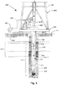
- FIG. 1 is a diagram of a network 100 of sub-surface wells (Well1, Well2, ... , WellN) and at least one surface facility (e.g., a Sink, such as a holding tank), including intra-well (tnet1, tnet2, ..., tnetN) subdivisions of the network 100, and inter-well (xnet) subdivisions of the network 100, according to various embodiments of the disclosure.
- a reservoir simulator may operate to couple the simulation of reservoir sub-grids 110 and grid blocks 112, and the simulation of the network of wells (e.g., Well1, Well2, ... , WellN) and surface facilities (e.g., Sink).
- the wells Well1, Well2, ... , WellN perforate the reservoir grid blocks 112, via nodes (shown as large black dots in the figure) inside the reservoir grid 106.
- the nodes represent physical objects/locations at which the wells Well1, Well2, ... , WellN can produce or inject fluid.
- the network 100 often has a tree-like structure, with each branch of the tree structure being a well. Fluid from the wells Well1, Well2, ... , WellN may flow directly to sinks (e.g., storage tanks), or flow from sources, or join at one or more common gathering centers.
- sinks e.g., storage tanks
- Parallel computing is a useful paradigm in modern numerical simulation.
- One method commonly used to parallelize a numerical problem is to subdivide the problem into multiple domains, so that computations can be performed in parallel over each domain. This mechanism utilizes communication among the domain processors for those calculations that require the transfer of information between domains.
- the reservoir grid 106 shown in FIG. 1 could be divided into several sub-grids 1 10, each of which represents a computational domain and contains one or more grid blocks 112, and any calculation that involves only local variables, such as evaluation of the fluid properties within that domain, can be performed in parallel with other domains.
- each processor only performs calculations for part of the reservoir. In this way, the CPU time used by each processor, and the elapsed time to solve the whole problem, can be reduced when compared to performing the calculations for each domain serially, on a single processor.
- the network 100 includes wells Well1, Well2, ... , WellN, connected pipelines, and surface facilities.
- the network 100 also includes connections 124 and nodes (represented by large black dots).
- Some types of connections 124 include well tubing strings, pipes, valves, chokes (that reduce the flow in a pipe by reducing diameter), and pumps, among others.
- Some types of nodes include perforation inlets (sources) 128, perforation outlets, tubing heads 132, gathering centers 136, distribution centers 140, separators, coolers, heaters, and fractionation columns, among others.
- Boundary conditions are set by network sink and source pressures, source fluid compositions, perforated reservoir grid block pressures, and fluid mobilities.
- Network equations include connection equations imposed at connections, perforation equations imposed at perforations, and mass balance equations imposed at nodes.
- a set of processors can be set up to solve for the network unknowns in parallel, so that the unknowns include the pressures and fluid compositions at nodes, the total fluid flow rates at connections 124, and the total fluid flow rates at perforations 128. These equations are linearized and solved using a number of Newton iterations.
- Various facility constraints can be imposed at different points within the network, such as a maximum flow rate constraint at a connection, a maximum flow rate constraint on the sum of flow rates of a group of connections, or a minimum pressure constraint at a node, etc.
- a slack variable solution method known to those of ordinary skill in the art, can be applied to determine which constraints are active during an iterative network solution procedure.
- the network 100 can be divided into sub-networks. Each sub-network that contains all perforations, connections, and nodes for a single well, up to the connection to the first gathering node for that well, is referred to as a "tnet”. Once a network 100 is divided into one or more tnets, the remaining part of the network (including the first gathering node that the wells join to) is referred to as an "xnet”. The xnet receives contributions from multiple tnets, and is used to model interactions between wells. In some embodiments, the network has no xnet (e.g., each well might connect directly to a holding facility).
- a relatively small network 100 of three tnets 114 joined by one xnet 118 is shown.
- the variable y t1 represents the tnet1 unknowns (e.g., composition and pressure at nodes, total flow rate at connections, and total perforation flow rate at perforations).
- the variable y t2 represents the tnet2 unknowns
- the variable y tN represents the tnetN unknowns.
- the variable y x represents the xnet unknowns (e.g., composition and pressure at nodes, and total flow rate at connections - there is no perforation flow rate, since the xnet does not represent a well).
- the variables r t1 , r t2 , r tN , r x are residuals of the equations of tnet1, tnet2, tnetN and the xnet, respectively.
- the Jacobian matrix is written in the form of multiple sub-matrices.
- sub-matrices A t1t1 , A t1t2 , A t1tN , and A t1x contain the network equation coefficients of tnet1 that multiply network unknowns of the sub-networks tnet1, tnet2, tnetN, and xnet, respectively; the other sub-matrices are similar, as will be understood by those of ordinary skill in the art, upon studying the content of this disclosure.
- sub-matrices A t1t2 and A t2t1 would be empty if there was no cross-connection between tnet1 and tnet2; sub-matrices A t1tN and A tNt1 would be empty if there was no cross-connection between tnet1 and tnetN.
- cross-connections between tnets, as shown in the figure.
- Such cross-connections are referred to as a "cnet" 120.
- These cross-connections are of two types: physical and logical.
- Physical cnet cross-connections in the network 100 represent physical network devices, such as pipes, which connect tnets. Other examples include connections to re-inject part of the produced fluid into an injection well, or the connections to re-inject part of the produced gas into production well tubing for gaslift. In essence, a physical cnet cross-connection represents any physical device that communicates flow from one tnet to another.
- Logical cnet cross-connections in the network 100 represent a logical relationship between tnets.
- An example might be a maximum total oil phase rate constraint on a group of wells.
- the logical connection represents the degree of this indirect effect
- cnets both cnets and xnets connect multiple tnets. Therefore, in most embodiments, cnets are treated as part of the xnet when the equation system for the network 100 is set up.
- Active network constraints can be determined using the slack variable method during the solution of the network equation system; in this case, slack variables are additional unknowns of the network equation system which are associated with the same number of constraint equations.
- These constraint equations can be put at the end of the network equations of the corresponding tnet and xnet, and the slack variable unknowns can be put at the end of the network unknowns of each corresponding tnet and xnet
- the solution of the reservoir grid and network coupled system can be obtained using Newton iterations, where the network with a fixed reservoir grid condition (fluid pressure and mobilities at perforated grid blocks) is solved at the beginning of each iteration, or time step.
- This process is referred to herein as the "standalone network solution process”.
- the standalone network solution process is completed for a series of Newton iterations, the reservoir grid and network are combined for global solution, as an overall equation system, also using a series of Newton iterations in a "global solution process".
- the complete procedure is discussed in detail in conjunction with FIG. 5 , and is described generally in the following paragraphs.
- a nn actually contains the entire Jacobian matrix of equation (1).
- y n and y r are the network unknowns and reservoir grid unknowns, respectively.
- r n and r r are the residuals of network equations and reservoir grid equations, respectively.
- Both the standalone network solution process and the global solution process involve construction and factoring a Jacobian matrix of the network equations, i.e., the entire Jacobian matrix of equation (1), and the matrix A nn in equation (2). That is, parallelizing network computations applies to both the standalone network solution process and the reservoir-network global solution process. Thus, the method of parallelizing computations described below applies to each process, and is scalable to a much greater degree than conventional methods.
- message passing can be performed between parallel processes using any standard parallel message passing package, such as MPI (the Message Passing Interface, a standard for message passing that includes a library of message passing functions).
- MPI the Message Passing Interface
- This standard includes MPI Version 2.2, released by the Message Passing Interface Forum on September 4, 2009.
- tnets and xnets are assigned to different processors. For example, referring to FIG. 1 , if there are three processors (P1, P2, P3) available, tnet1 can be assigned to processor 1 (P1), tnet2 can be assigned to processor 2 (P2), and tnetN and the xnet (including the cnet) can be assigned to processor 3 (P3). In other words, the unknowns of each sub-network can be assigned to different processors.
- the network Jacobian matrix is constructed in a distributed manner. That is, each processor only needs to determine the coefficients of the unknowns local to that particular processor.
- the unknowns y t1 can be assigned to processor P1
- the unknowns y t2 can be assigned to processor P2
- the unknowns y tN and y x can be assigned to processor P3.
- sub-matrices A t1t1 , A t2t1 , A tNt1 and A xt1 are constructed solely by processor P1
- sub-matrices A t1t2 , A t2t2 , A tNt2 and A xt2 are constructed solely by processor P2
- sub-matrices A t1x , A t2x , A tNx and A xx are constructed solely by processor P3.
- Parallel message passing is used to communicate the data at the boundary connections/nodes between a tnet and another tnet, or between a tnet and an xnet (if such inter-connections exist). These data are used to construct sub-matrices A t1t2 , A t1tN , A t1x , A t2t1 , A t2tN , A t2x , A tNt1 , A tNt2 , A tNx , A xt1 , A xt2 , and A xtN .
- a partial factorization in parallel can be performed using a parallel linear solver, which will return the resulting Schur complement matrix to the host processor (e.g., the processor with a rank of zero in the MPI communicator, which can be any processor among the processors P1, P2, and P3).
- Partial factorization operates to eliminate network unknowns, including the pressures and fluid compositions at nodes, and total fluid flow rates at connections and perforations.
- the resulting Schur complement matrix is used to solve for Schur variables, which are slack variables, in the host processor (e.g., the processor with a rank of zero in the MPI communicator). Then, the solver can be used to back-solve for the network unknowns in parallel.
- the network unknowns are updated using the solution of the current Newton iteration.
- the parallel processing Newton iteration (as part of the standalone network solution process) is incremented and repeated until convergence is determined.
- a generic version of a global solution process of reservoir and network integrated system is documented in Reference [1], noted above.
- This process involves the construction and factoring of the Jacobian matrix of the network equation, i.e., the Jacobian matrix in equation (1) or A nn in equation (2), and the general solution of network unknowns, at each global Newton iteration.
- the parallelization method described herein is also applied to this global solution process, i.e., the network Jacobian matrix is constructed in a distributed manner, then a partial factorization in parallel can be performed using a parallel linear solver, which will return the resulting Schur complement matrix to the host processor (e.g., the processor with a rank of zero in the MPI communicator).
- the resulting Schur complement matrix is used to solve for Schur variables, which are slack variables, in the host processor.
- the parallel linear solver can be used to back-solve for the network unknowns in parallel.
- the parallelization of network computations can reduce the elapsed time and the CPU time of individual processor when compared to traditional sequential computation. This is because, first, the hydraulic pressure drop computations and IPR computations for all tnets connections will be performed in parallel on different processors, instead of sequentially on one or all processors. Calculation time is reduced, especially when there are a large number of wells, when the number of connections is large, and/or when computationally-expensive flash calculations are used to determine fluid phase behavior in the network. Second, the factorization of network Jacobian matrix and the solution of network unknowns are now performed in parallel. Various embodiments that include some or all of these features will now be described in detail.
- FIG. 2 is a block diagram of a system embodiment of the disclosure.
- a system 264 includes a housing 204.
- the housing 204 might take the form of a wireline tool body or a down hole tool, such as a logging while drilling tool or a measurement while drilling tool, among others.
- Processors 230 (P 0 , P 1 , P 2 , P 3 , ... P N ) within the system 264 may be located at the surface 266, as part of a surface logging facility 256, or in a data acquisition system 224, which may be above or below the Earth's surface 266 (e.g., attached to the housing 204).
- the processors 230 may comprise multiple computational units, some located down hole, and some at the surface 266.
- a system 264 may further comprise a data transceiver 244 (e.g., a telemetry transmitter and/or receiver) to transmit acquired data 248 (e.g., formation and fluid property information, perhaps including fluid phase behavior) from sensors S to the surface logging facility 256.
- Logic 240 can be used to acquire the data as signals, according to the various methods described herein.
- Acquired data 248, as well as other data, can be stored in the memory 250, perhaps as part of a database 234. Formation and fluid property information, equation unknowns, the content of Jacobian matrices, residues, and other values may be stored in the memory 250.
- a system 264 that comprises a housing 204 and one or more processors 230, which may be located down hole or at the surface 266.
- a system 264 comprises a down hole housing 204 that acquires data 248 (e.g., formation and fluid property information, perhaps including fluid phase behavior) in real time, which feeds into the parallel processing algorithm described above so that the dynamic behavior of the network 100, including the reservoir grid 106, the wells Well1, Well2, ..., WellN, sinks (e.g., the manifold 268 and the holding facility 270), and cross-connects (e.g., gas lift injection 260) can be observed in real time.
- data 248 e.g., formation and fluid property information, perhaps including fluid phase behavior
- sinks e.g., the manifold 268 and the holding facility 270
- cross-connects e.g., gas lift injection 260
- the parallel processing algorithm runs on a parallel processing computer (e.g., workstation 256) that is located in a lab or an office.
- the processors 230 are housed down hole.
- the processing is split between processors 230 at the surface, and processors 230 down hole, using real time data 248 acquired via down hole sensors S. High-speed telemetry may be used to communicate information between processors.
- the data stored in the memory 250 may include any number of parameters, including seismic interpolation data, earth modeling data, fluid and rock properties, surface facility configurations, and production history, among others.
- the results of reservoir simulation can be used for field development planning and optimization.
- a system 264 comprises a housing 204 having sensors S to be operated in a first well Well1.
- the system 264 may also comprise a number of processors 230 communicatively coupled to the housing 204.
- the processors 230 may operate to receive data 248 (e.g., formation and fluid property information) from the sensors S, and to compute, in parallel, to determine values of unknowns in network equations associated with a network 100 of sub-surface wells Well1, Well2, ..., WellN, and at least one surface facility (e.g., the holding facility 270), for intra-well (tnet) subdivisions of the network, and then for inter-well (xnet) subdivisions of the network 100.
- data 248 e.g., formation and fluid property information
- the network equations comprise connection equations, perforation equations, and mass balance equations.
- the act of computing is based on default values of the unknowns, or prior determined values of the unknowns, along with the formation and fluid property information.
- the processors 230 may operate to construct a distributed Jacobian matrix having portions comprising coefficients of the unknowns distributed among the number of processors 230, wherein each of the portions is distributed to a particular one of the processors previously assigned to corresponding ones of the subdivisions.
- the processors 230 may operate to at least partially factor, in parallel, the Jacobian matrix to provide factors and eliminate some of the unknowns, including at least one of pressures at nodes, fluid compositions at nodes, or flow rates at connections.
- the processors 230 may also operate to back-solve, in parallel, for any remaining unsolved ones of the unknowns, using the factors.
- the data 248 acquired from the sensors S can be selected to achieve specific goals, such as providing information that can be used to improve production output. For example, measurements of pressure and flow rates might be useful to tune the input to the simulation, so that predictions provided by the simulation (e.g., for the next hour, day, or some other selected time period that might be useful to control well operations) are as close to actual past behavior as possible.
- an automated history matching process is implemented to tune the simulator input so that simulator output predictions more closely match actual behavior during a selected prior time period, such as the past day or week. In this way, the predictions for the next day, week, etc. should be more reliable.
- Simulator inputs amenable to tuning include reservoir (grid block) parameters, such as permeability, rock compressibility, and relative permeability; well completion properties, such as the skin factor; pipe properties, including roughness, or a choice of pressure drop correlation (e.g., Hagedorn versus Beggs & Brill); fluid properties (e.g., equation of state parameters or black oil tables); and many more.
- reservoir grid block
- well completion properties such as the skin factor
- pipe properties including roughness, or a choice of pressure drop correlation (e.g., Hagedorn versus Beggs & Brill); fluid properties (e.g., equation of state parameters or black oil tables); and many more.
- Prediction outputs that might be used to improve production output include choke and valve settings, well workovers (e.g., plugging or opening perforations), scheduling the drilling of wells, reconfiguring the surface network (e.g., adding or removing pipes, rerouting pipes to avoid bottlenecks, adding or removing separators, and rerouting or reconfiguring separators to maximize oil production) and so on.
- downhole and surface information can be used as simulator input, to adjust and enhance simulator operation, and/or field operations, ultimately providing a simulation output that can be used to adjust valves, chokes, etc. in a manual or automated fashion).
- the data 248 that is acquired can be selected to provide output values of the unknowns associated with physical device operations (e.g., operations of chokes, valves, separators, etc.) forming part of the network and/or one or more surface facilities.
- physical device operations e.g., operations of chokes, valves, separators, etc.
- one or more of the formation information, fluid property information, flow rate information, or pressure information is selected to provide input values that are used to calibrate the network and reservoir equations.
- the values of the unknowns determined by the network and reservoir equations are used to automatically adjust the operation of physical devices.
- Telemetry can be used to send the data (e.g., formation and fluid property information) to the surface for processing in a parallel processing workstation.
- a transceiver 244 e.g., including a telemetry transmitter
- a transceiver 244 attached to the housing 204 can be used to communicate the acquired data 248 to a surface data processing facility 256.
- Wireline or down hole (e.g., drilling) tools can be used as a specific form of the housing.
- the housing 204 may comprise one of a wireline tool or a down hole tool. Additional embodiments may be realized, and thus, some additional examples of systems will now be described.
- FIG. 3 illustrates a wireline system 364 embodiment of the disclosure
- FIG. 4 illustrates a drilling rig system 464 embodiment of the disclosure. Therefore, the systems 364, 464 may comprise portions of a wireline logging tool body 370 as part of a wireline logging operation, or of a down hole tool 428 as part of a down hole drilling operation.
- the systems 364 and 464 may comprise any one or more elements of the system 264 shown in FIG. 2 .
- FIG. 3 shows a well during wireline logging operations.
- a drilling platform 386 is equipped with a derrick 388 that supports a hoist 390.
- Drilling oil and gas wells is commonly carried out using a string of drill pipes connected together so as to form a drilling string that is lowered through a rotary table 310 into a wellbore or borehole 312.
- the drilling string has been temporarily removed from the borehole 312 to allow a wireline logging tool body 370, such as a probe or sonde, to be lowered by wireline or logging cable 374 into the borehole 312.
- a wireline logging tool body 370 such as a probe or sonde
- the wireline logging tool body 370 is lowered to the bottom of the region of interest and subsequently pulled upward at a substantially constant speed.
- various instruments included in the tool body 370 may be used to perform measurements (e.g., made by portions of the system 264 shown in FIG. 2 ) on the subsurface geological formations 314 adjacent the borehole 312 (and the tool body 370).
- the borehole 312 may represent one or more offset wells, or a target well.
- the measurement data (e.g., formation and fluid property information) can be communicated to a surface logging facility 392 for processing, analysis, and/or storage.
- the logging facility 392 may be provided with electronic equipment for various types of signal processing, which may be implemented by any one or more of the components of the system 264 in FIG. 2 .
- Similar formation evaluation data may be gathered and analyzed during drilling operations (e.g., during logging while drilling operations, and by extension, sampling while drilling).
- the tool body 370 is suspended in the wellbore by a wireline cable 374 that connects the tool to a surface control unit (e.g., comprising a workstation 354).
- the tool may be deployed in the borehole 312 on coiled tubing, jointed drill pipe, hard wired drill pipe, or any other suitable deployment technique.
- a system 464 may also form a portion of a drilling rig 402 located at the surface 404 of a well 406.
- the drilling rig 402 may provide support for a drill string 408.
- the drill string 408 may operate to penetrate the rotary table 310 for drilling the borehole 312 through the subsurface formations 314.
- the drill string 408 may include a Kelly 416, drill pipe 418, and a bottom hole assembly 420, perhaps located at the lower portion of the drill pipe 418.
- the bottom hole assembly 420 may include drill collars 422, a down hole tool 424, and a drill bit 426.
- the drill bit 426 may operate to create the borehole 312 by penetrating the surface 404 and the subsurface formations 314.
- the down hole tool 424 may comprise any of a number of different types of tools including measurement while drilling tools, logging while drilling tools, and others.
- the drill string 408 (perhaps including the Kelly 416, the drill pipe 418, and the bottom hole assembly 420) may be rotated by the rotary table 310.
- the bottom hole assembly 420 may also be rotated by a motor (e.g., a mud motor) that is located down hole.
- the drill collars 422 may be used to add weight to the drill bit 426.
- the drill collars 422 may also operate to stiffen the bottom hole assembly 420, allowing the bottom hole assembly 420 to transfer the added weight to the drill bit 426, and in turn, to assist the drill bit 426 in penetrating the surface 404 and subsurface formations 314.
- a mud pump 432 may pump drilling fluid (sometimes known by those of ordinary skill in the art as "drilling mud") from a mud pit 434 through a hose 436 into the drill pipe 418 and down to the drill bit 426.
- the drilling fluid can flow out from the drill bit 426 and be returned to the surface 404 through an annular area between the drill pipe 418 and the sides of the borehole 312.
- the drilling fluid may then be returned to the mud pit 434, where such fluid is filtered.
- the drilling fluid can be used to cool the drill bit 426, as well as to provide lubrication for the drill bit 426 during drilling operations. Additionally, the drilling fluid may be used to remove subsurface formation cuttings created by operating the drill bit 426.
- the systems 364, 464 may include a drill collar 422, a down hole tool 424, and/or a wireline logging tool body 370 to house one or more systems 264, or portions of those systems 264, described above and illustrated in FIG. 2 .
- housing may include any one or more of a drill collar 422, a down hole tool 424, or a wireline logging tool body 370 (all having an outer surface, to enclose or attach to sensors, magnetometers, fluid sampling devices, pressure measurement devices, temperature measurement devices, transmitters, receivers, acquisition and processing logic, and data acquisition systems).
- the tool 424 may comprise a down hole tool, such as an LWD tool or MWD tool.
- the wireline tool body 370 may comprise a wireline logging tool, including a probe or sonde, for example, coupled to a logging cable 374. Many embodiments may thus be realized.
- a system 364, 464 may include a display 396 to present simulator behavior, as well as database information (e.g., measured values of formation and fluid property information), perhaps in graphic form.
- database information e.g., measured values of formation and fluid property information
- the network 100 reservoir grid 106; sub-grids 110; grid blocks 112; intra-well network subdivisions (tnet1, tnet2, ..., tnetN) 114; inter-well network subdivisions (xnets) 118; cross-connections (cnets) 120; connections 124; perforations 128; tubing heads 132; gathering centers 136; distribution centers 140; housing 204; wells (Well1 , Well2, ... , WellN) 210; processors (P 0 , P 1 , P 2 , P 3 , ...
- Such modules may include hardware circuitry, and/or a processor and/or memory circuits, software program modules and objects, and/or firmware, and combinations thereof, as desired by the architect of the systems 264, 364, 464 and as appropriate for particular implementations of various embodiments.
- such modules may be included in an apparatus and/or system operation simulation package, such as a software electrical signal simulation package, a power usage and distribution simulation package, a power/heat dissipation simulation package, and/or a combination of software and hardware used to simulate the operation of various potential embodiments.
- Applications that may include the novel apparatus and systems of various embodiments include electronic circuitry used in high-speed computers, communication and signal processing circuitry, modems, processor modules, embedded processors, data switches, and application-specific modules. Such apparatus and systems may further be included as sub-components within a variety of electronic systems, such as televisions, cellular telephones, personal computers, workstations, radios, video players, vehicles, signal processing for geothermal tools and smart transducer interface node telemetry systems, among others. Some embodiments include a number of methods.
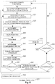
- FIG. 5 is a flow chart illustrating several methods 511 according to various embodiments of the disclosure.
- the methods 511 may comprise processor-implemented methods, to execute on one or more processors that perform the methods, in parallel.
- a network of wells and surface facilities can be represented by a linearized system of network equations.
- the coefficients of these equations can be determined by dividing the network into intra-well (tnet) subdivisions, and inter-well (xnet) subdivisions.
- Each processor is assigned to one or more of the subdivisions (tnets and/or xnets), and is used to solve, in parallel, for the unknowns associated with their assigned subdivisions.
- the basic method 511 may include parallel processing to compute hydraulic pressure drop and IPR (Inflow Performance Relationship) s at every connection (as a function of at least one of the unknowns associated with some of the sub-surface wells), construct a single Jacobian matrix, factor the matrix, and back-solve for any remaining unsolved unknowns, in a series of Newton iterations.
- IPR Inflow Performance Relationship
- This standalone network solution process is embedded in an over-arching global solution process, also comprising a number of Newton iterations.
- one embodiment of the methods 511 may begin at blocks 513, 515, and 521 with the first Newton iteration of the standalone network solution process, over a given time interval.
- the method 511 may continue on to block 525 with computing, in parallel, hydraulic pressure drop and inflow performance relationships associated with a network of sub-surface wells and at least one surface facility, for intra-well subdivisions of the network, and then for inter-well subdivisions of the network, based on the values of the previous Newton iteration; these computations are necessary to construct the Jacobian matrix of the network equations, wherein the network equations comprise connection equations, perforation equations, and mass balance equations, and wherein the computing is based on default values of the unknowns, or prior determined values of the unknowns.
- the physical network of wells and surface facilities may be divided into parts (e.g., intra-well subdivisions and inter-well subdivisions) that make up a tree-structure.
- the subdivisions are coupled together, using physical and logical connections, according to a tree structure.
- the network equations may comprise a variety of equations that describe the network operations, including hydraulic pressure drop equations (a type of connection equation) or an inflow performance relationship (a type of perforation equation).
- the network equations comprise equations used to determine at least one of a hydraulic pressure drop or an inflow performance relationship for some of the sub-surface wells.
- a cnet has the same types of network equations as an xnet.
- equation (1) for example, the equations and unknowns for the xnet include the equations and unknowns of the cnet.
- the cnet can also contain auxiliary variables, such as a facility constraint, or a reinjection composition.
- a facility constraint might require that the sum of water rates from the producing wells be less than the amount of water capacity of the facility. The constraint may be satisfied by reducing the water rate of the well producing the highest fraction of water (e.g., the highest water cut), which might be known as the "swing well”.
- An auxiliary variable t can be introduced, which is equal to the facility water capacity: the sum of the water production rates of all wells associated with the facility, except the swing well. This variable t would then form a part of the xnet.
- inter-well subdivisions may comprise cross-connections (cnets) between the intra-well subdivisions.
- the method 511 may continue on to block 529 with constructing a distributed Jacobian matrix having portions comprising coefficients of the unknowns distributed among the number of processors, wherein each of the portions is distributed to a particular one of the processors previously assigned to corresponding ones of the subdivisions.
- An MPI library can be accessed to communicate data from one boundary connection/node in a first subdivision, to another boundary connection/node in another subdivision. For example, from one tnet to another, or from one tnet to an xnet.
- the activity at block 529 may comprise accessing an MPI library during the construction of the Jacobian matrix, to communicate data between the subdivisions/processors.
- the method 511 may continue on to block 533 to include at least partially factoring, in parallel, the Jacobian matrix to provide factors and eliminate some of the unknowns including at least one of pressures at nodes, fluid compositions at nodes, or flow rates at connections.
- a parallel linear solver can be used to factor the Jacobian matrix.
- the activity at block 533 may comprise using a parallel linear solver to accomplish the factoring.
- the MPI library can be used to define a host processor, which can be designated to receive complement matrix (e.g., Schur matrix) values that result from the factoring.
- complement matrix e.g., Schur matrix
- the method 511 may continue on to block 537 to include, after the factoring, transmitting the complement matrix to a single processor included in the number of processors.
- Slack variables comprise additional unknowns having a one-to-one correspondence with the same number of network constraint equations. These variables can be determined as part of the solution process. Thus, the method 511 may continue on to block 545 with solving for unknowns as slack variables associated with the complement matrix using the single processor.
- the determined values of slack variables may be associated with a matrix comprising the factors (produced by the factoring activity in block 533).
- the complement matrix may comprise a Schur matrix.
- the activity of determining variables at block 545 may comprise solving for the unknowns as slack variables associated with a Schur complement matrix on one of the number of processors. That is, the complement matrix values can be used by the host processor to determine Schur variables as slack variables.
- the method 511 may continue on to block 549 with back-solving, in parallel, for any remaining unsolved ones of the network unknowns, using the factors produced by the factoring activity in block 533.
- a parallel linear solver can be used to back-solve for the unsolved unknowns.
- the activity at block 549 may comprise using a parallel linear solver to accomplish the back-solving.
- the slack variables can be used to help back-solve for remaining unsolved unknowns, improving the solution efficiency.
- the activity at block 549 may comprise back-solving, in parallel, for any remaining unsolved ones of the network unknowns, using the factors and the determined values of the slack variables.
- Each of the activities in the portion of the method 511 that is used to determine the standalone network solution can be repeated as a series of Newton solution iterations, to converge to a solution of the values of the unknowns.
- the method 511 may continue on to block 553, with a test for convergence.
- the method 5 11 may return to block 521 to execute another network Newton iteration.
- the method 511 may comprise repeating the computing, the constructing, the factoring, and the back-solving as a series of Newton solution iterations (the standalone iterations 555) to refine the values of the unknowns until residuals associated with the unknowns have been reduced below a first selected threshold value, as determined at block 553.
- the method 511 may continue on to block 561 with repeatedly testing (at blocks 561-569) for convergence in a global set of equations (e.g., equation (2), and the global iterations 577) that describe the behavior of a reservoir associated with the network equations, to refine the values of unknowns in the global set of equations until residuals associated with the unknowns in the global set of equations have been reduced below a second selected threshold value, as determined at block 561.
- the method 511 may return to block 515 to begin the next reservoir and network Newton iteration.
- the unknowns that have been determined can be published (e.g., shown on a display, printed on paper, or stored in a non-transitory memory).
- the method 511 may continue on to block 573 with publishing the values of at least some of the unknowns, perhaps in graphical form on a display.
- the method 511 may comprise repeating the computing, the constructing, the factoring, and the back-solving as a first series of Newton solution iterations 555; and solving a global set of equations describing a reservoir associated with the network equations as a second series of Newton solution iterations 577, in which each one of the second series of Newton solution iterations contains at least one of the first series of Newton solution iterations.
- a software program can be launched from a computer-readable medium in a computer-based system to execute the functions defined in the software program.
- One of ordinary skill in the art will further understand the various programming languages (e.g., FORTRAN 95) that may be employed to create one or more software programs designed to implement and perform the methods disclosed herein.
- the programs may be structured in an object-orientated format using an object-oriented language such as Java or C#.
- the programs can be structured in a procedure-orientated format using a procedural language, such as assembly or C.
- the software components may communicate using any of a number of mechanisms well known to those skilled in the art, such as application program interfaces or interprocess communication techniques, including remote procedure calls.
- application program interfaces or interprocess communication techniques, including remote procedure calls.
- remote procedure calls The teachings of various embodiments are not limited to any particular programming language or environment. Thus, other embodiments may be realized.
- FIG. 6 is a block diagram of an article 600 of manufacture according to various embodiments, such as a computer, a memory system, a magnetic or optical disk, or some other storage device.
- the article 600 may include one or more processors 616 coupled to a machine-accessible medium such as a memory 636 (e.g., removable storage media, as well as any tangible, non-transitory machine-accessible medium (e.g., a memory including an electrical, optical, or electromagnetic conductor) having associated information 638 (e.g., computer program instructions and/or data), which when accessed by one or more of the processors 616, results in a machine (e.g., the article 600) performing any of the actions described with respect to the methods of FIG.
- a machine-accessible medium such as a memory 636 (e.g., removable storage media, as well as any tangible, non-transitory machine-accessible medium (e.g., a memory including an electrical, optical, or electromagnetic conductor) having associated information 638 (e.g
- the processors 616 may comprise one or more processors sold by Intel Corporation (e.g., Intel® CoreTM processor family), Advanced Micro Devices (e.g., AMD AthlonTM processors), and other semiconductor manufacturers.
- the article 600 may comprise one or more processors 616 coupled to a display 618 to display data processed by the processor 616 and/or a wireless transceiver 620 (e.g., a down hole telemetry transceiver) to receive and transmit data processed by the processor.
- a wireless transceiver 620 e.g., a down hole telemetry transceiver
- the memory system(s) included in the article 600 may include memory 636 comprising volatile memory (e.g., dynamic random access memory) and/or non-volatile memory.
- the memory 636 may be used to store data 640 processed by the processor 616, including corrected compressional wave velocity data that is associated with a first (e.g., target) well, where no measured shear wave velocity data is available.
- the article 600 may comprise communication apparatus 622, which may in turn include amplifiers 626 (e.g., preamplifiers or power amplifiers) and one or more transducers 624 (e.g., transmitting and/or receiving devices, such as acoustic transducers). Signals 642 received or transmitted by the communication apparatus 622 may be processed according to the methods described herein.
- amplifiers 626 e.g., preamplifiers or power amplifiers
- transducers 624 e.g., transmitting and/or receiving devices, such as acoustic transducers.
- the article 600 may comprise a down hole tool, including any one or more elements of the system 264 shown in FIG. 2 .
- the apparatus, systems, and methods disclosed herein can use nested Newton iterations, and parallel processing, to scale the solution of network simulations, so that the CPU time of individual processors (and therefore, the elapsed simulation time) is reduced to a significant degree, when compared to conventional mechanisms.
- the ability to achieve increased processing efficiency in this area can greatly enhance the value of the services provided by an operation/exploration company.
Landscapes
- Life Sciences & Earth Sciences (AREA)
- Engineering & Computer Science (AREA)
- Geology (AREA)
- Mining & Mineral Resources (AREA)
- Physics & Mathematics (AREA)
- Environmental & Geological Engineering (AREA)
- Fluid Mechanics (AREA)
- General Life Sciences & Earth Sciences (AREA)
- Geochemistry & Mineralogy (AREA)
- Geophysics (AREA)
- Management, Administration, Business Operations System, And Electronic Commerce (AREA)
- Geophysics And Detection Of Objects (AREA)
Claims (17)
- System (264), umfassend:ein Gehäuse (204), das Sensoren (S) aufweist, für den Betrieb in einem ersten Bohrloch (210); undeine Anzahl an Prozessoren (230), die kommunikativ an das Gehäuse gekoppelt ist, wobei die Prozessoren dazu dienen, Formations- und/oder Fluideigenschaftsinformationen von den Sensoren zu empfangen, und um parallel zu berechnen, um Werte von Unbekannten in Netzwerkgleichungen in Verbindung mit einem Netzwerk aus unterirdischen Bohrlöchern (210) und zumindest einer Oberflächeneinrichtung für Intra-Well-(tnet-)Teildivisionen des Netzwerks (100) und dann für Inter-Well-(xnet-)Teildivisionen des Netzwerks zu bestimmen, wobei die Unbekannten jeder Teildivision des Netzwerks unterschiedlichen Prozessoren zuweisbar sind, wobei die Netzwerkgleichungen Verbindungsgleichungen, Perforationsgleichungen und Massenausgleichsgleichungen umfassen, und wobei das Berechnen auf Standardwerten der Unbekannten oder zuvor bestimmten Werten der Unbekannten zusammen mit den Formations- und/oder Fluideigenschaftsinformationen basiert,eine verteilte Jacobi-Matrix zu erstellen, die Teile aufweist, die Koeffizienten der Unbekannten verteilt auf die Anzahl an Prozessoren umfassen, wobei jeder der Teile auf einen bestimmten der Prozessoren verteilt ist, der zuvor entsprechenden der Teildivisionen zugewiesen wurde, und wobei jeder Prozessor (230) lediglich die Koeffizienten der Unbekannten lokal zu dem bestimmen Prozessor bestimmen muss;die Jacobi-Matrix zumindest partiell parallel zu berücksichtigen, um Faktoren bereitzustellen und einige der Unbekannten zu streichen, darunter zumindest eines von Drücken an Knoten, Fluidzusammensetzungen an Knoten oder Flussraten an Verbindungen; undum für beliebige übrige ungelöste der Unbekannten unter Verwendung der Faktoren parallel ein Backsolving durchzuführen.
- System nach Anspruch 1, wobei die Werte der Unbekannten bestimmt durch die Netzgleichungen verwendet werden, um den Betrieb der physischen Vorrichtungen automatisch einzustellen.
- System nach Anspruch 1, ferner umfassend:
einen Telemetrie-Sender (244), der an dem Gehäuse (204) angebracht ist, wobei der Telemetrie-Sender dazu dient, die Formations- und/oder Fluideigenschaftsinformationen einer Oberflächendatenverarbeitungseinrichtung (256) zu kommunizieren. - System nach Anspruch 1, wobei das Gehäuse eines von einem Drahtleitungswerkzeug (370) oder einem Untertagewerkzeug (428) umfasst.
- System nach Anspruch 1, wobei zumindest einer aus der Anzahl an Prozessoren in dem Gehäuse untergebracht ist, oder wobei die Anzahl an Prozessoren in einer Oberflächendatenverarbeitungseinrichtung (256) untergebracht ist.
- System nach Anspruch 1, wobei zumindest eine der Formations- und/oder Fluideigenschaftsinformationen, Flussrateninformationen oder Druckinformationen verwendet wird, um Eingabewerte bereitzustellen, die verwendet werden können, um die Netzwerkgleichungen zu kalibrieren.
- Prozessorimplementiertes Verfahren zur Verwendung in einem System (264), umfassend ein Gehäuse (204), das Sensoren (S) aufweist, für den Betrieb in einem ersten Bohrloch (210), und eine Anzahl an Prozessoren (230), die kommunikativ an das Gehäuse gekoppelt ist, wobei die Anzahl an Prozessoren das Verfahren durchführt, das Folgendes umfasst:Empfangen von Formations- und/oder Fluideigenschaftsinformationen von den Sensoren;paralleles Berechnen, um Werte von Unbekannten in Netzwerkgleichungen in Verbindung mit einem Netzwerk aus unterirdischen Bohrlöchern und zumindest einer Oberflächeneinrichtung (256) für Intra-Well-(tnet-)Teildivisionen des Netzwerks und dann für Inter-Well-(xnet-)Teildivisionen des Netzwerks zu bestimmen, wobei die Unbekannten jeder Teildivision des Netzwerks unterschiedlichen Prozessoren zuweisbar sind, wobei die Netzwerkgleichungen Verbindungsgleichungen, Perforationsgleichungen und Massenausgleichsgleichungen umfassen, und wobei das Berechnen auf Standardwerten der Unbekannten oder zuvor bestimmten Werten der Unbekannten basiert;Erstellen einer verteilten Jacobi-Matrix, die Teile aufweist, die Koeffizienten der Unbekannten verteilt auf die Anzahl an Prozessoren umfassen, wobei jeder der Teile auf einen bestimmten der Prozessoren verteilt ist, der zuvor entsprechenden der Teildivisionen zugewiesen wurde, und wobei jeder Prozessor lediglich die Koeffizienten der Unbekannten lokal zu dem bestimmen Prozessor bestimmen muss;zumindest partielles paralleles Berücksichtigen der Jacobi-Matrix, um Faktoren bereitzustellen und einige der Unbekannten zu streichen, darunter zumindest eines von Drücken an Knoten, Fluidzusammensetzungen an Knoten oder Flussraten an Verbindungen; undparalleles Backsolving für beliebige übrige ungelöste der Unbekannten unter Verwendung der Faktoren.
- Verfahren nach Anspruch 7, wobei die Teildivisionen unter Verwendung physischer und logischer Verbindungen gemäß einer Baumstruktur aneinander gekoppelt werden.
- Verfahren nach Anspruch 7, wobei die Netzwerkgleichungen Gleichungen umfassen, die verwendet werden, um zumindest eines von einem hydraulischen Druckabfall oder einer Eingangsflussleistungsbeziehung in Abhängigkeit von zumindest einer der Unbekannten in Verbindung mit einigen der unterirdischen Bohrlöcher zu bestimmen.
- Verfahren nach Anspruch 7, ferner umfassend:
Bestimmen von Werten von Schlupfvariablen als bestimmte Werte in Verbindung mit einer Matrix, die die Faktoren umfasst. - Verfahren nach Anspruch 10, wobei das Bestimmen der Werte von Schlupfvariablen Folgendes umfasst:
Lösen von Unbekannten als Schlupfvariable in Verbindung mit einer Schurkomplementmatrix an einem aus der Anzahl an Prozessoren. - Verfahren nach Anspruch 10, wobei das Backsolving Folgendes umfasst:
paralleles Backsolving für beliebige übrige ungelöste der Unbekannten unter Verwendung der Faktoren und der bestimmten Werte. - Verfahren nach Anspruch 7, ferner umfassend:
Wiederholen des Berechnens, des Erstellens, des Berücksichtigens und des Backsolvings als Newton-Lösungsiterationen, um die Werte der Unbekannten zu verfeinern, bis Reste in Verbindung mit den Unbekannten unter einen ersten ausgewählten Schwellenwert reduziert worden sind, und ferner umfassend:
wiederholtes Testen auf Konvergenz in einem globalen Satz an Gleichungen, der einen Speicher beschreibt, in Verbindung mit den Netzwerkgleichungen, beim Reduzieren der Reste in Verbindung mit den Unbekannten in den Netzwerkgleichungen unter den ersten ausgewählten Schwellenwert, um die Werte von Unbekannten in dem globalen Satz an Gleichungen zu verfeinern, bis Reste in Verbindung mit den Unbekannten in dem globalen Satz an Gleichungen unter einen zweiten ausgewählten Schwellenwert reduziert worden sind. - Verfahren nach Anspruch 7, wobei die Inter-Well-Teildivisionen Kreuzverbindungen (cnets) zwischen den Intra-Well-Teildivisionen umfassen.
- Artikel, beinhaltend ein nichtflüchtiges maschinenzugängliches Medium, in dem Anweisungen gespeichert sind, wobei die Anweisungen, wenn auf sie durch eine Anzahl an Prozessoren (230) in einem System (264) gemäß Anspruch 1 zugegriffen wird, zu einer Maschinendurchführung des Verfahrens nach Anspruch 7 führen.
- Artikel nach Anspruch 15, wobei die Anweisungen, wenn auf sie zugegriffen wird, dazu führen, dass die Maschine Folgendes durchführt:
Zugreifen auf eine Nachrichtenweiterleitungsschnittstellen-(MPI-)Bibliothek während der Erstellung, um Daten zwischen den Teildivisionen zu kommunizieren. - Artikel nach Anspruch 15, wobei die Anweisungen, wenn auf sie zugegriffen wird, dazu führen, dass die Maschine Folgendes durchführt:Übertragen einer Komplementmatrix an einen einzelnen Prozessor, der in der Anzahl an Prozessoren enthalten ist, nach dem Berücksichtigen; undLösen für die Unbekannten als Schlupfvariablen in Verbindung mit der Komplementmatrix unter Verwendung des einzelnen Prozessors, und/oder wobei die Anweisungen, wenn auf sie zugegriffen wird, dazu führen, dass die Maschine Folgendes durchführt:Wiederholen des Berechnens, des Erstellens, des Berücksichtigens und des Backsolvings als eine erste Reihe an Newton-Lösungsiterationen; undLösen eines globalen Satzes an Gleichungen, der einen Speicher beschreibt, in Verbindung mit den Netzwerkgleichungen als eine zweite Reihe an Newton-Lösungsiterationen, in der jede aus der zweiten Reihe an Newton-Lösungsiterationen zumindest eine aus der ersten Reihe an Newton-Lösungsiterationen enthält.
Applications Claiming Priority (1)
| Application Number | Priority Date | Filing Date | Title |
|---|---|---|---|
| PCT/US2012/042728 WO2013187915A2 (en) | 2012-06-15 | 2012-06-15 | Parallel network simulation apparatus, methods, and systems |
Publications (3)
| Publication Number | Publication Date |
|---|---|
| EP2862121A2 EP2862121A2 (de) | 2015-04-22 |
| EP2862121A4 EP2862121A4 (de) | 2016-07-27 |
| EP2862121B1 true EP2862121B1 (de) | 2019-06-19 |
Family
ID=49758832
Family Applications (1)
| Application Number | Title | Priority Date | Filing Date |
|---|---|---|---|
| EP12878865.0A Active EP2862121B1 (de) | 2012-06-15 | 2012-06-15 | Parallele netzwerksimulationsvorrichtung, verfahren und systeme |
Country Status (6)
| Country | Link |
|---|---|
| US (1) | US10253600B2 (de) |
| EP (1) | EP2862121B1 (de) |
| AU (1) | AU2012382415B2 (de) |
| CA (1) | CA2876583C (de) |
| RU (1) | RU2014149896A (de) |
| WO (1) | WO2013187915A2 (de) |
Families Citing this family (20)
| Publication number | Priority date | Publication date | Assignee | Title |
|---|---|---|---|---|
| US10087721B2 (en) | 2010-07-29 | 2018-10-02 | Exxonmobil Upstream Research Company | Methods and systems for machine—learning based simulation of flow |
| CA2807300C (en) | 2010-09-20 | 2017-01-03 | Exxonmobil Upstream Research Company | Flexible and adaptive formulations for complex reservoir simulations |
| AU2011332274B2 (en) | 2010-11-23 | 2017-02-23 | Exxonmobil Upstream Research Company | Variable discretization method for flow simulation on complex geological models |
| EP2862121B1 (de) | 2012-06-15 | 2019-06-19 | Landmark Graphics Corporation | Parallele netzwerksimulationsvorrichtung, verfahren und systeme |
| WO2014051903A1 (en) | 2012-09-28 | 2014-04-03 | Exxonmobil Upstream Research Company | Fault removal in geological models |
| US20140219056A1 (en) * | 2013-02-04 | 2014-08-07 | Halliburton Energy Services, Inc. ("HESI") | Fiberoptic systems and methods for acoustic telemetry |
| EP2971481A2 (de) | 2013-03-14 | 2016-01-20 | GeoDynamics, Inc. | Erweiterte perforationsmodellierung |
| US9835012B2 (en) * | 2014-03-12 | 2017-12-05 | Landmark Graphics Corporation | Simplified compositional models for calculating properties of mixed fluids in a common surface network |
| CN103955186B (zh) * | 2014-04-22 | 2016-08-24 | 中国石油大学(北京) | 天然气管网管流状态参数确定方法及装置 |
| EP3175265A1 (de) | 2014-07-30 | 2017-06-07 | ExxonMobil Upstream Research Company | Verfahren zur erzeugung eines volumetrischen gitters in einem bereich mit heterogenen materialeigenschaften |
| US10803534B2 (en) | 2014-10-31 | 2020-10-13 | Exxonmobil Upstream Research Company | Handling domain discontinuity with the help of grid optimization techniques |
| US11409023B2 (en) | 2014-10-31 | 2022-08-09 | Exxonmobil Upstream Research Company | Methods to handle discontinuity in constructing design space using moving least squares |
| WO2016073418A1 (en) * | 2014-11-03 | 2016-05-12 | Schlumberger Canada Limited | Assessing whether to modify a pipe system |
| WO2018005214A1 (en) * | 2016-06-28 | 2018-01-04 | Schlumberger Technology Corporation | Parallel multiscale reservoir simulation |
| US10570705B2 (en) | 2016-11-04 | 2020-02-25 | Landmark Graphics Corporation | Managing a network of wells and surface facilities by finding a steady-state flow solution for a pipe sub-network |
| GB2570223B (en) * | 2016-11-04 | 2021-08-11 | Landmark Graphics Corp | Determining active constraints in a network using pseudo slack variables |
| US10839114B2 (en) | 2016-12-23 | 2020-11-17 | Exxonmobil Upstream Research Company | Method and system for stable and efficient reservoir simulation using stability proxies |
| IT201700045152A1 (it) | 2017-04-26 | 2018-10-26 | Nuovo Pignone Tecnologie Srl | Metodo e sistema per operazioni di modellazione di un impianto fisico |
| US10570706B2 (en) | 2017-06-23 | 2020-02-25 | Saudi Arabian Oil Company | Parallel-processing of invasion percolation for large-scale, high-resolution simulation of secondary hydrocarbon migration |
| WO2021150468A1 (en) * | 2020-01-20 | 2021-07-29 | Schlumberger Technology Corporation | Methods and systems for reservoir simulation |
Family Cites Families (10)
| Publication number | Priority date | Publication date | Assignee | Title |
|---|---|---|---|---|
| WO2009059045A2 (en) * | 2007-10-30 | 2009-05-07 | University Of Utah Research Foundation | Fast iterative method for processing hamilton-jacobi equations |
| US7668707B2 (en) * | 2007-11-28 | 2010-02-23 | Landmark Graphics Corporation | Systems and methods for the determination of active constraints in a network using slack variables and plurality of slack variable multipliers |
| BRPI0919457A2 (pt) * | 2008-09-30 | 2015-12-01 | Exxonmobil Upstream Res Co | método para simular escoamento de fluido em um reservatório de hidrocarboneto |
| US8793112B2 (en) | 2009-08-14 | 2014-07-29 | Bp Corporation North America Inc. | Reservoir architecture and connectivity analysis |
| BR112012010094A2 (pt) * | 2009-10-28 | 2016-05-31 | Chevron Usa Inc | método de volume finito em multiescala para uso na simulação de um modelo geológico de escala fina de um reservatório de subsuperfície, sistema para uso em simulação de um modelo geológico de escala fina de um reservatório de subsuperfície, e, software |
| CN102741855B (zh) * | 2010-02-12 | 2016-10-26 | 埃克森美孚上游研究公司 | 用于将并行模拟模型分区的方法和系统 |
| US8386227B2 (en) * | 2010-09-07 | 2013-02-26 | Saudi Arabian Oil Company | Machine, computer program product and method to generate unstructured grids and carry out parallel reservoir simulation |
| US8433551B2 (en) * | 2010-11-29 | 2013-04-30 | Saudi Arabian Oil Company | Machine, computer program product and method to carry out parallel reservoir simulation |
| US8437999B2 (en) * | 2011-02-08 | 2013-05-07 | Saudi Arabian Oil Company | Seismic-scale reservoir simulation of giant subsurface reservoirs using GPU-accelerated linear equation systems |
| EP2862121B1 (de) | 2012-06-15 | 2019-06-19 | Landmark Graphics Corporation | Parallele netzwerksimulationsvorrichtung, verfahren und systeme |
-
2012
- 2012-06-15 EP EP12878865.0A patent/EP2862121B1/de active Active
- 2012-06-15 WO PCT/US2012/042728 patent/WO2013187915A2/en not_active Ceased
- 2012-06-15 AU AU2012382415A patent/AU2012382415B2/en not_active Ceased
- 2012-06-15 US US14/406,805 patent/US10253600B2/en active Active
- 2012-06-15 CA CA2876583A patent/CA2876583C/en active Active
- 2012-06-15 RU RU2014149896A patent/RU2014149896A/ru not_active Application Discontinuation
Non-Patent Citations (1)
| Title |
|---|
| None * |
Also Published As
| Publication number | Publication date |
|---|---|
| US20150134314A1 (en) | 2015-05-14 |
| CA2876583A1 (en) | 2013-12-19 |
| RU2014149896A (ru) | 2016-08-10 |
| AU2012382415A1 (en) | 2014-12-11 |
| WO2013187915A3 (en) | 2014-05-08 |
| CA2876583C (en) | 2016-11-08 |
| US10253600B2 (en) | 2019-04-09 |
| WO2013187915A2 (en) | 2013-12-19 |
| EP2862121A4 (de) | 2016-07-27 |
| AU2012382415B2 (en) | 2015-08-20 |
| EP2862121A2 (de) | 2015-04-22 |
Similar Documents
| Publication | Publication Date | Title |
|---|---|---|
| EP2862121B1 (de) | Parallele netzwerksimulationsvorrichtung, verfahren und systeme | |
| CA2649439C (en) | Dynamic reservoir engineering | |
| CA2707482C (en) | A method for performing oilfield production operations | |
| CA2874994C (en) | Systems and methods for solving a multi-reservoir system with heterogeneous fluids coupled to a common gathering network | |
| US11512573B2 (en) | Stimulation using fiber-derived information and fracturing modeling | |
| NO20190677A1 (en) | Coupled reservoir-geomechanical models using compaction tables | |
| US12360285B2 (en) | Well intervention performance system | |
| US20230359793A1 (en) | Machine-learning calibration for petroleum system modeling | |
| US20260049900A1 (en) | Assessing the health of a production facility | |
| US20250347215A1 (en) | Subsurface knowledge enhancement using data science-constrained inverse modelling | |
| US20240094433A1 (en) | Integrated autonomous operations for injection-production analysis and parameter selection | |
| US20260078660A1 (en) | Generative ai agents for production engineering in oil and gas | |
| CA3045880C (en) | Coupled reservoir-geomechanical models using compaction tables | |
| WO2025101591A1 (en) | Physics informed machine learning for discrete nonlinear partial differential equations | |
| WO2025128808A1 (en) | Oilfield data product generation and management system | |
| AU2023347241A1 (en) | System for automated model building and scenario evaluation through concept generation | |
| EP4260272A1 (de) | Verarbeitung von unterirdischen daten mit unsicherheit für modellierung und feldplanung |
Legal Events
| Date | Code | Title | Description |
|---|---|---|---|
| PUAI | Public reference made under article 153(3) epc to a published international application that has entered the european phase |
Free format text: ORIGINAL CODE: 0009012 |
|
| 17P | Request for examination filed |
Effective date: 20141204 |
|
| AK | Designated contracting states |
Kind code of ref document: A2 Designated state(s): AL AT BE BG CH CY CZ DE DK EE ES FI FR GB GR HR HU IE IS IT LI LT LU LV MC MK MT NL NO PL PT RO RS SE SI SK SM TR |
|
| AX | Request for extension of the european patent |
Extension state: BA ME |
|
| DAX | Request for extension of the european patent (deleted) | ||
| REG | Reference to a national code |
Ref country code: DE Ref legal event code: R079 Ref document number: 602012061299 Country of ref document: DE Free format text: PREVIOUS MAIN CLASS: G06G0007500000 Ipc: E21B0043000000 |
|
| A4 | Supplementary search report drawn up and despatched |
Effective date: 20160628 |
|
| RIC1 | Information provided on ipc code assigned before grant |
Ipc: E21B 47/00 20120101ALI20160622BHEP Ipc: E21B 43/00 20060101AFI20160622BHEP Ipc: E21B 47/10 20120101ALI20160622BHEP |
|
| STAA | Information on the status of an ep patent application or granted ep patent |
Free format text: STATUS: EXAMINATION IS IN PROGRESS |
|
| 17Q | First examination report despatched |
Effective date: 20170804 |
|
| GRAP | Despatch of communication of intention to grant a patent |
Free format text: ORIGINAL CODE: EPIDOSNIGR1 |
|
| STAA | Information on the status of an ep patent application or granted ep patent |
Free format text: STATUS: GRANT OF PATENT IS INTENDED |
|
| INTG | Intention to grant announced |
Effective date: 20190121 |
|
| GRAS | Grant fee paid |
Free format text: ORIGINAL CODE: EPIDOSNIGR3 |
|
| GRAA | (expected) grant |
Free format text: ORIGINAL CODE: 0009210 |
|
| STAA | Information on the status of an ep patent application or granted ep patent |
Free format text: STATUS: THE PATENT HAS BEEN GRANTED |
|
| AK | Designated contracting states |
Kind code of ref document: B1 Designated state(s): AL AT BE BG CH CY CZ DE DK EE ES FI FR GB GR HR HU IE IS IT LI LT LU LV MC MK MT NL NO PL PT RO RS SE SI SK SM TR |
|
| REG | Reference to a national code |
Ref country code: GB Ref legal event code: FG4D |
|
| REG | Reference to a national code |
Ref country code: CH Ref legal event code: EP |
|
| REG | Reference to a national code |
Ref country code: IE Ref legal event code: FG4D |
|
| REG | Reference to a national code |
Ref country code: AT Ref legal event code: REF Ref document number: 1145742 Country of ref document: AT Kind code of ref document: T Effective date: 20190715 |
|
| REG | Reference to a national code |
Ref country code: DE Ref legal event code: R096 Ref document number: 602012061299 Country of ref document: DE |
|
| REG | Reference to a national code |
Ref country code: NO Ref legal event code: T2 Effective date: 20190619 |
|
| REG | Reference to a national code |
Ref country code: NL Ref legal event code: MP Effective date: 20190619 |
|
| PG25 | Lapsed in a contracting state [announced via postgrant information from national office to epo] |
Ref country code: FI Free format text: LAPSE BECAUSE OF FAILURE TO SUBMIT A TRANSLATION OF THE DESCRIPTION OR TO PAY THE FEE WITHIN THE PRESCRIBED TIME-LIMIT Effective date: 20190619 Ref country code: HR Free format text: LAPSE BECAUSE OF FAILURE TO SUBMIT A TRANSLATION OF THE DESCRIPTION OR TO PAY THE FEE WITHIN THE PRESCRIBED TIME-LIMIT Effective date: 20190619 Ref country code: SE Free format text: LAPSE BECAUSE OF FAILURE TO SUBMIT A TRANSLATION OF THE DESCRIPTION OR TO PAY THE FEE WITHIN THE PRESCRIBED TIME-LIMIT Effective date: 20190619 Ref country code: AL Free format text: LAPSE BECAUSE OF FAILURE TO SUBMIT A TRANSLATION OF THE DESCRIPTION OR TO PAY THE FEE WITHIN THE PRESCRIBED TIME-LIMIT Effective date: 20190619 Ref country code: LT Free format text: LAPSE BECAUSE OF FAILURE TO SUBMIT A TRANSLATION OF THE DESCRIPTION OR TO PAY THE FEE WITHIN THE PRESCRIBED TIME-LIMIT Effective date: 20190619 |
|
| REG | Reference to a national code |
Ref country code: LT Ref legal event code: MG4D |
|
| PG25 | Lapsed in a contracting state [announced via postgrant information from national office to epo] |
Ref country code: BG Free format text: LAPSE BECAUSE OF FAILURE TO SUBMIT A TRANSLATION OF THE DESCRIPTION OR TO PAY THE FEE WITHIN THE PRESCRIBED TIME-LIMIT Effective date: 20190919 Ref country code: GR Free format text: LAPSE BECAUSE OF FAILURE TO SUBMIT A TRANSLATION OF THE DESCRIPTION OR TO PAY THE FEE WITHIN THE PRESCRIBED TIME-LIMIT Effective date: 20190920 Ref country code: RS Free format text: LAPSE BECAUSE OF FAILURE TO SUBMIT A TRANSLATION OF THE DESCRIPTION OR TO PAY THE FEE WITHIN THE PRESCRIBED TIME-LIMIT Effective date: 20190619 Ref country code: LV Free format text: LAPSE BECAUSE OF FAILURE TO SUBMIT A TRANSLATION OF THE DESCRIPTION OR TO PAY THE FEE WITHIN THE PRESCRIBED TIME-LIMIT Effective date: 20190619 |
|
| REG | Reference to a national code |
Ref country code: AT Ref legal event code: MK05 Ref document number: 1145742 Country of ref document: AT Kind code of ref document: T Effective date: 20190619 |
|
| PG25 | Lapsed in a contracting state [announced via postgrant information from national office to epo] |
Ref country code: RO Free format text: LAPSE BECAUSE OF FAILURE TO SUBMIT A TRANSLATION OF THE DESCRIPTION OR TO PAY THE FEE WITHIN THE PRESCRIBED TIME-LIMIT Effective date: 20190619 Ref country code: SK Free format text: LAPSE BECAUSE OF FAILURE TO SUBMIT A TRANSLATION OF THE DESCRIPTION OR TO PAY THE FEE WITHIN THE PRESCRIBED TIME-LIMIT Effective date: 20190619 Ref country code: EE Free format text: LAPSE BECAUSE OF FAILURE TO SUBMIT A TRANSLATION OF THE DESCRIPTION OR TO PAY THE FEE WITHIN THE PRESCRIBED TIME-LIMIT Effective date: 20190619 Ref country code: AT Free format text: LAPSE BECAUSE OF FAILURE TO SUBMIT A TRANSLATION OF THE DESCRIPTION OR TO PAY THE FEE WITHIN THE PRESCRIBED TIME-LIMIT Effective date: 20190619 Ref country code: PT Free format text: LAPSE BECAUSE OF FAILURE TO SUBMIT A TRANSLATION OF THE DESCRIPTION OR TO PAY THE FEE WITHIN THE PRESCRIBED TIME-LIMIT Effective date: 20191021 Ref country code: NL Free format text: LAPSE BECAUSE OF FAILURE TO SUBMIT A TRANSLATION OF THE DESCRIPTION OR TO PAY THE FEE WITHIN THE PRESCRIBED TIME-LIMIT Effective date: 20190619 Ref country code: CZ Free format text: LAPSE BECAUSE OF FAILURE TO SUBMIT A TRANSLATION OF THE DESCRIPTION OR TO PAY THE FEE WITHIN THE PRESCRIBED TIME-LIMIT Effective date: 20190619 |
|
| PG25 | Lapsed in a contracting state [announced via postgrant information from national office to epo] |
Ref country code: SM Free format text: LAPSE BECAUSE OF FAILURE TO SUBMIT A TRANSLATION OF THE DESCRIPTION OR TO PAY THE FEE WITHIN THE PRESCRIBED TIME-LIMIT Effective date: 20190619 Ref country code: IT Free format text: LAPSE BECAUSE OF FAILURE TO SUBMIT A TRANSLATION OF THE DESCRIPTION OR TO PAY THE FEE WITHIN THE PRESCRIBED TIME-LIMIT Effective date: 20190619 Ref country code: ES Free format text: LAPSE BECAUSE OF FAILURE TO SUBMIT A TRANSLATION OF THE DESCRIPTION OR TO PAY THE FEE WITHIN THE PRESCRIBED TIME-LIMIT Effective date: 20190619 Ref country code: IS Free format text: LAPSE BECAUSE OF FAILURE TO SUBMIT A TRANSLATION OF THE DESCRIPTION OR TO PAY THE FEE WITHIN THE PRESCRIBED TIME-LIMIT Effective date: 20191019 |
|
| PG25 | Lapsed in a contracting state [announced via postgrant information from national office to epo] |
Ref country code: TR Free format text: LAPSE BECAUSE OF FAILURE TO SUBMIT A TRANSLATION OF THE DESCRIPTION OR TO PAY THE FEE WITHIN THE PRESCRIBED TIME-LIMIT Effective date: 20190619 |
|
| PG25 | Lapsed in a contracting state [announced via postgrant information from national office to epo] |
Ref country code: PL Free format text: LAPSE BECAUSE OF FAILURE TO SUBMIT A TRANSLATION OF THE DESCRIPTION OR TO PAY THE FEE WITHIN THE PRESCRIBED TIME-LIMIT Effective date: 20190619 Ref country code: DK Free format text: LAPSE BECAUSE OF FAILURE TO SUBMIT A TRANSLATION OF THE DESCRIPTION OR TO PAY THE FEE WITHIN THE PRESCRIBED TIME-LIMIT Effective date: 20190619 |
|
| PG25 | Lapsed in a contracting state [announced via postgrant information from national office to epo] |
Ref country code: IS Free format text: LAPSE BECAUSE OF FAILURE TO SUBMIT A TRANSLATION OF THE DESCRIPTION OR TO PAY THE FEE WITHIN THE PRESCRIBED TIME-LIMIT Effective date: 20200224 |
|
| REG | Reference to a national code |
Ref country code: DE Ref legal event code: R097 Ref document number: 602012061299 Country of ref document: DE |
|
| PLBE | No opposition filed within time limit |
Free format text: ORIGINAL CODE: 0009261 |
|
| STAA | Information on the status of an ep patent application or granted ep patent |
Free format text: STATUS: NO OPPOSITION FILED WITHIN TIME LIMIT |
|
| PG2D | Information on lapse in contracting state deleted |
Ref country code: IS |
|
| 26N | No opposition filed |
Effective date: 20200603 |
|
| PG25 | Lapsed in a contracting state [announced via postgrant information from national office to epo] |
Ref country code: SI Free format text: LAPSE BECAUSE OF FAILURE TO SUBMIT A TRANSLATION OF THE DESCRIPTION OR TO PAY THE FEE WITHIN THE PRESCRIBED TIME-LIMIT Effective date: 20190619 |
|
| REG | Reference to a national code |
Ref country code: DE Ref legal event code: R119 Ref document number: 602012061299 Country of ref document: DE |
|
| PG25 | Lapsed in a contracting state [announced via postgrant information from national office to epo] |
Ref country code: MC Free format text: LAPSE BECAUSE OF FAILURE TO SUBMIT A TRANSLATION OF THE DESCRIPTION OR TO PAY THE FEE WITHIN THE PRESCRIBED TIME-LIMIT Effective date: 20190619 |
|
| REG | Reference to a national code |
Ref country code: CH Ref legal event code: PL |
|
| PG25 | Lapsed in a contracting state [announced via postgrant information from national office to epo] |
Ref country code: LU Free format text: LAPSE BECAUSE OF NON-PAYMENT OF DUE FEES Effective date: 20200615 |
|
| REG | Reference to a national code |
Ref country code: BE Ref legal event code: MM Effective date: 20200630 |
|
| PG25 | Lapsed in a contracting state [announced via postgrant information from national office to epo] |
Ref country code: LI Free format text: LAPSE BECAUSE OF NON-PAYMENT OF DUE FEES Effective date: 20200630 Ref country code: IE Free format text: LAPSE BECAUSE OF NON-PAYMENT OF DUE FEES Effective date: 20200615 Ref country code: CH Free format text: LAPSE BECAUSE OF NON-PAYMENT OF DUE FEES Effective date: 20200630 Ref country code: FR Free format text: LAPSE BECAUSE OF NON-PAYMENT OF DUE FEES Effective date: 20200630 |
|
| PG25 | Lapsed in a contracting state [announced via postgrant information from national office to epo] |
Ref country code: BE Free format text: LAPSE BECAUSE OF NON-PAYMENT OF DUE FEES Effective date: 20200630 Ref country code: DE Free format text: LAPSE BECAUSE OF NON-PAYMENT OF DUE FEES Effective date: 20210101 |
|
| PG25 | Lapsed in a contracting state [announced via postgrant information from national office to epo] |
Ref country code: MT Free format text: LAPSE BECAUSE OF FAILURE TO SUBMIT A TRANSLATION OF THE DESCRIPTION OR TO PAY THE FEE WITHIN THE PRESCRIBED TIME-LIMIT Effective date: 20190619 Ref country code: CY Free format text: LAPSE BECAUSE OF FAILURE TO SUBMIT A TRANSLATION OF THE DESCRIPTION OR TO PAY THE FEE WITHIN THE PRESCRIBED TIME-LIMIT Effective date: 20190619 |
|
| PG25 | Lapsed in a contracting state [announced via postgrant information from national office to epo] |
Ref country code: MK Free format text: LAPSE BECAUSE OF FAILURE TO SUBMIT A TRANSLATION OF THE DESCRIPTION OR TO PAY THE FEE WITHIN THE PRESCRIBED TIME-LIMIT Effective date: 20190619 |
|
| PGFP | Annual fee paid to national office [announced via postgrant information from national office to epo] |
Ref country code: GB Payment date: 20250401 Year of fee payment: 14 |
|
| PGFP | Annual fee paid to national office [announced via postgrant information from national office to epo] |
Ref country code: NO Payment date: 20250522 Year of fee payment: 14 |