EP2861984B1 - Method and system for use in monitoring biological material - Google Patents
Method and system for use in monitoring biological material Download PDFInfo
- Publication number
- EP2861984B1 EP2861984B1 EP13737424.5A EP13737424A EP2861984B1 EP 2861984 B1 EP2861984 B1 EP 2861984B1 EP 13737424 A EP13737424 A EP 13737424A EP 2861984 B1 EP2861984 B1 EP 2861984B1
- Authority
- EP
- European Patent Office
- Prior art keywords
- container
- gas
- wavelengths
- biological material
- concentration
- Prior art date
- Legal status (The legal status is an assumption and is not a legal conclusion. Google has not performed a legal analysis and makes no representation as to the accuracy of the status listed.)
- Active
Links
- 239000012620 biological material Substances 0.000 title claims description 115
- 238000000034 method Methods 0.000 title claims description 79
- 238000012544 monitoring process Methods 0.000 title description 39
- CURLTUGMZLYLDI-UHFFFAOYSA-N Carbon dioxide Chemical compound O=C=O CURLTUGMZLYLDI-UHFFFAOYSA-N 0.000 claims description 220
- 230000002503 metabolic effect Effects 0.000 claims description 176
- 229910002092 carbon dioxide Inorganic materials 0.000 claims description 135
- 239000001569 carbon dioxide Substances 0.000 claims description 131
- 244000005700 microbiome Species 0.000 claims description 104
- 238000010521 absorption reaction Methods 0.000 claims description 91
- 238000000855 fermentation Methods 0.000 claims description 84
- 230000004151 fermentation Effects 0.000 claims description 84
- 238000001514 detection method Methods 0.000 claims description 73
- 238000005259 measurement Methods 0.000 claims description 63
- 230000003595 spectral effect Effects 0.000 claims description 61
- 230000003287 optical effect Effects 0.000 claims description 59
- 230000005540 biological transmission Effects 0.000 claims description 35
- 238000002835 absorbance Methods 0.000 claims description 34
- 238000004891 communication Methods 0.000 claims description 31
- 239000012530 fluid Substances 0.000 claims description 24
- 239000000463 material Substances 0.000 claims description 24
- 238000011065 in-situ storage Methods 0.000 claims description 22
- 238000003860 storage Methods 0.000 claims description 21
- 230000006870 function Effects 0.000 claims description 20
- 238000001228 spectrum Methods 0.000 claims description 18
- 238000012545 processing Methods 0.000 claims description 17
- 230000008859 change Effects 0.000 claims description 15
- 238000009792 diffusion process Methods 0.000 claims description 11
- 230000008569 process Effects 0.000 claims description 10
- 238000011109 contamination Methods 0.000 claims description 9
- 230000001427 coherent effect Effects 0.000 claims description 7
- 238000007405 data analysis Methods 0.000 claims description 2
- 239000007789 gas Substances 0.000 description 227
- 230000009102 absorption Effects 0.000 description 79
- 241000894006 Bacteria Species 0.000 description 23
- 230000001580 bacterial effect Effects 0.000 description 17
- 238000004519 manufacturing process Methods 0.000 description 16
- 239000000523 sample Substances 0.000 description 16
- 230000004071 biological effect Effects 0.000 description 15
- 239000001963 growth medium Substances 0.000 description 15
- 239000002028 Biomass Substances 0.000 description 14
- LFQSCWFLJHTTHZ-UHFFFAOYSA-N Ethanol Chemical compound CCO LFQSCWFLJHTTHZ-UHFFFAOYSA-N 0.000 description 14
- 238000005070 sampling Methods 0.000 description 12
- 230000035945 sensitivity Effects 0.000 description 12
- 210000004027 cell Anatomy 0.000 description 11
- 230000000875 corresponding effect Effects 0.000 description 11
- 238000004476 mid-IR spectroscopy Methods 0.000 description 11
- 235000013305 food Nutrition 0.000 description 10
- 108090000623 proteins and genes Proteins 0.000 description 10
- 239000000126 substance Substances 0.000 description 10
- 238000002834 transmittance Methods 0.000 description 10
- 239000012503 blood component Substances 0.000 description 9
- 230000001276 controlling effect Effects 0.000 description 9
- 235000018102 proteins Nutrition 0.000 description 9
- 102000004169 proteins and genes Human genes 0.000 description 9
- 102000007056 Recombinant Fusion Proteins Human genes 0.000 description 8
- 108010008281 Recombinant Fusion Proteins Proteins 0.000 description 8
- 239000008280 blood Substances 0.000 description 8
- 210000004369 blood Anatomy 0.000 description 8
- 230000012010 growth Effects 0.000 description 8
- 238000011534 incubation Methods 0.000 description 8
- 230000004044 response Effects 0.000 description 8
- 238000000862 absorption spectrum Methods 0.000 description 6
- 238000004458 analytical method Methods 0.000 description 6
- 238000002474 experimental method Methods 0.000 description 6
- 230000004060 metabolic process Effects 0.000 description 6
- VNWKTOKETHGBQD-UHFFFAOYSA-N methane Chemical compound C VNWKTOKETHGBQD-UHFFFAOYSA-N 0.000 description 6
- 238000009825 accumulation Methods 0.000 description 5
- QVGXLLKOCUKJST-UHFFFAOYSA-N atomic oxygen Chemical compound [O] QVGXLLKOCUKJST-UHFFFAOYSA-N 0.000 description 5
- KRKNYBCHXYNGOX-UHFFFAOYSA-N citric acid Chemical compound OC(=O)CC(O)(C(O)=O)CC(O)=O KRKNYBCHXYNGOX-UHFFFAOYSA-N 0.000 description 5
- 235000019441 ethanol Nutrition 0.000 description 5
- 230000001965 increasing effect Effects 0.000 description 5
- 239000001301 oxygen Substances 0.000 description 5
- 229910052760 oxygen Inorganic materials 0.000 description 5
- 229920001817 Agar Polymers 0.000 description 4
- QGZKDVFQNNGYKY-UHFFFAOYSA-N Ammonia Chemical compound N QGZKDVFQNNGYKY-UHFFFAOYSA-N 0.000 description 4
- 241000588724 Escherichia coli Species 0.000 description 4
- MWUXSHHQAYIFBG-UHFFFAOYSA-N Nitric oxide Chemical compound O=[N] MWUXSHHQAYIFBG-UHFFFAOYSA-N 0.000 description 4
- RAHZWNYVWXNFOC-UHFFFAOYSA-N Sulphur dioxide Chemical compound O=S=O RAHZWNYVWXNFOC-UHFFFAOYSA-N 0.000 description 4
- 239000008272 agar Substances 0.000 description 4
- 230000008901 benefit Effects 0.000 description 4
- JJWKPURADFRFRB-UHFFFAOYSA-N carbonyl sulfide Chemical compound O=C=S JJWKPURADFRFRB-UHFFFAOYSA-N 0.000 description 4
- 238000007796 conventional method Methods 0.000 description 4
- 238000005286 illumination Methods 0.000 description 4
- 230000006698 induction Effects 0.000 description 4
- NOESYZHRGYRDHS-UHFFFAOYSA-N insulin Chemical compound N1C(=O)C(NC(=O)C(CCC(N)=O)NC(=O)C(CCC(O)=O)NC(=O)C(C(C)C)NC(=O)C(NC(=O)CN)C(C)CC)CSSCC(C(NC(CO)C(=O)NC(CC(C)C)C(=O)NC(CC=2C=CC(O)=CC=2)C(=O)NC(CCC(N)=O)C(=O)NC(CC(C)C)C(=O)NC(CCC(O)=O)C(=O)NC(CC(N)=O)C(=O)NC(CC=2C=CC(O)=CC=2)C(=O)NC(CSSCC(NC(=O)C(C(C)C)NC(=O)C(CC(C)C)NC(=O)C(CC=2C=CC(O)=CC=2)NC(=O)C(CC(C)C)NC(=O)C(C)NC(=O)C(CCC(O)=O)NC(=O)C(C(C)C)NC(=O)C(CC(C)C)NC(=O)C(CC=2NC=NC=2)NC(=O)C(CO)NC(=O)CNC2=O)C(=O)NCC(=O)NC(CCC(O)=O)C(=O)NC(CCCNC(N)=N)C(=O)NCC(=O)NC(CC=3C=CC=CC=3)C(=O)NC(CC=3C=CC=CC=3)C(=O)NC(CC=3C=CC(O)=CC=3)C(=O)NC(C(C)O)C(=O)N3C(CCC3)C(=O)NC(CCCCN)C(=O)NC(C)C(O)=O)C(=O)NC(CC(N)=O)C(O)=O)=O)NC(=O)C(C(C)CC)NC(=O)C(CO)NC(=O)C(C(C)O)NC(=O)C1CSSCC2NC(=O)C(CC(C)C)NC(=O)C(NC(=O)C(CCC(N)=O)NC(=O)C(CC(N)=O)NC(=O)C(NC(=O)C(N)CC=1C=CC=CC=1)C(C)C)CC1=CN=CN1 NOESYZHRGYRDHS-UHFFFAOYSA-N 0.000 description 4
- 235000015097 nutrients Nutrition 0.000 description 4
- 230000035699 permeability Effects 0.000 description 4
- 238000000926 separation method Methods 0.000 description 4
- QTBSBXVTEAMEQO-UHFFFAOYSA-N Acetic acid Chemical compound CC(O)=O QTBSBXVTEAMEQO-UHFFFAOYSA-N 0.000 description 3
- WQZGKKKJIJFFOK-GASJEMHNSA-N Glucose Natural products OC[C@H]1OC(O)[C@H](O)[C@@H](O)[C@@H]1O WQZGKKKJIJFFOK-GASJEMHNSA-N 0.000 description 3
- 238000004566 IR spectroscopy Methods 0.000 description 3
- OKKJLVBELUTLKV-UHFFFAOYSA-N Methanol Chemical compound OC OKKJLVBELUTLKV-UHFFFAOYSA-N 0.000 description 3
- 230000009471 action Effects 0.000 description 3
- 238000013019 agitation Methods 0.000 description 3
- 238000013459 approach Methods 0.000 description 3
- 235000013361 beverage Nutrition 0.000 description 3
- 239000000306 component Substances 0.000 description 3
- 239000008103 glucose Substances 0.000 description 3
- 239000007788 liquid Substances 0.000 description 3
- 238000013178 mathematical model Methods 0.000 description 3
- 239000002609 medium Substances 0.000 description 3
- 230000000813 microbial effect Effects 0.000 description 3
- 238000004445 quantitative analysis Methods 0.000 description 3
- 230000029058 respiratory gaseous exchange Effects 0.000 description 3
- 241000894007 species Species 0.000 description 3
- 230000014616 translation Effects 0.000 description 3
- XKRFYHLGVUSROY-UHFFFAOYSA-N Argon Chemical compound [Ar] XKRFYHLGVUSROY-UHFFFAOYSA-N 0.000 description 2
- OKTJSMMVPCPJKN-UHFFFAOYSA-N Carbon Chemical compound [C] OKTJSMMVPCPJKN-UHFFFAOYSA-N 0.000 description 2
- RWSOTUBLDIXVET-UHFFFAOYSA-N Dihydrogen sulfide Chemical compound S RWSOTUBLDIXVET-UHFFFAOYSA-N 0.000 description 2
- 102000004190 Enzymes Human genes 0.000 description 2
- 108090000790 Enzymes Proteins 0.000 description 2
- OTMSDBZUPAUEDD-UHFFFAOYSA-N Ethane Chemical compound CC OTMSDBZUPAUEDD-UHFFFAOYSA-N 0.000 description 2
- VGGSQFUCUMXWEO-UHFFFAOYSA-N Ethene Chemical compound C=C VGGSQFUCUMXWEO-UHFFFAOYSA-N 0.000 description 2
- 239000005977 Ethylene Substances 0.000 description 2
- 102000004877 Insulin Human genes 0.000 description 2
- 108090001061 Insulin Proteins 0.000 description 2
- 241001465754 Metazoa Species 0.000 description 2
- 240000004808 Saccharomyces cerevisiae Species 0.000 description 2
- 238000005273 aeration Methods 0.000 description 2
- 229910021529 ammonia Inorganic materials 0.000 description 2
- 239000003242 anti bacterial agent Substances 0.000 description 2
- 229940088710 antibiotic agent Drugs 0.000 description 2
- 238000002617 apheresis Methods 0.000 description 2
- 235000013405 beer Nutrition 0.000 description 2
- 239000013060 biological fluid Substances 0.000 description 2
- BJQHLKABXJIVAM-UHFFFAOYSA-N bis(2-ethylhexyl) phthalate Chemical compound CCCCC(CC)COC(=O)C1=CC=CC=C1C(=O)OCC(CC)CCCC BJQHLKABXJIVAM-UHFFFAOYSA-N 0.000 description 2
- 239000001273 butane Substances 0.000 description 2
- WUKWITHWXAAZEY-UHFFFAOYSA-L calcium difluoride Chemical compound [F-].[F-].[Ca+2] WUKWITHWXAAZEY-UHFFFAOYSA-L 0.000 description 2
- 229910001634 calcium fluoride Inorganic materials 0.000 description 2
- 229910052799 carbon Inorganic materials 0.000 description 2
- 230000010261 cell growth Effects 0.000 description 2
- 239000000356 contaminant Substances 0.000 description 2
- 230000002596 correlated effect Effects 0.000 description 2
- 230000007423 decrease Effects 0.000 description 2
- 238000010586 diagram Methods 0.000 description 2
- 239000003814 drug Substances 0.000 description 2
- 230000000694 effects Effects 0.000 description 2
- 238000011067 equilibration Methods 0.000 description 2
- 230000004907 flux Effects 0.000 description 2
- 239000000446 fuel Substances 0.000 description 2
- 229910000037 hydrogen sulfide Inorganic materials 0.000 description 2
- 238000007689 inspection Methods 0.000 description 2
- 229940125396 insulin Drugs 0.000 description 2
- 230000010354 integration Effects 0.000 description 2
- 238000012417 linear regression Methods 0.000 description 2
- 230000007246 mechanism Effects 0.000 description 2
- 239000000203 mixture Substances 0.000 description 2
- IJDNQMDRQITEOD-UHFFFAOYSA-N n-butane Chemical compound CCCC IJDNQMDRQITEOD-UHFFFAOYSA-N 0.000 description 2
- OFBQJSOFQDEBGM-UHFFFAOYSA-N n-pentane Natural products CCCCC OFBQJSOFQDEBGM-UHFFFAOYSA-N 0.000 description 2
- 238000010899 nucleation Methods 0.000 description 2
- 238000000424 optical density measurement Methods 0.000 description 2
- 229920000642 polymer Polymers 0.000 description 2
- 230000035755 proliferation Effects 0.000 description 2
- 230000005855 radiation Effects 0.000 description 2
- 238000000611 regression analysis Methods 0.000 description 2
- 230000000241 respiratory effect Effects 0.000 description 2
- 238000007789 sealing Methods 0.000 description 2
- 238000004088 simulation Methods 0.000 description 2
- 108010027322 single cell proteins Proteins 0.000 description 2
- 238000004611 spectroscopical analysis Methods 0.000 description 2
- 238000012360 testing method Methods 0.000 description 2
- XLYOFNOQVPJJNP-UHFFFAOYSA-N water Substances O XLYOFNOQVPJJNP-UHFFFAOYSA-N 0.000 description 2
- 235000013618 yogurt Nutrition 0.000 description 2
- PXRKCOCTEMYUEG-UHFFFAOYSA-N 5-aminoisoindole-1,3-dione Chemical compound NC1=CC=C2C(=O)NC(=O)C2=C1 PXRKCOCTEMYUEG-UHFFFAOYSA-N 0.000 description 1
- 239000004382 Amylase Substances 0.000 description 1
- 102000013142 Amylases Human genes 0.000 description 1
- 108010065511 Amylases Proteins 0.000 description 1
- 102000016938 Catalase Human genes 0.000 description 1
- 108010053835 Catalase Proteins 0.000 description 1
- GZCGUPFRVQAUEE-AEKYUDOOSA-N D-glucose-(13)C6 Chemical compound O[13CH2][13C@@H](O)[13C@@H](O)[13C@H](O)[13C@@H](O)[13CH]=O GZCGUPFRVQAUEE-AEKYUDOOSA-N 0.000 description 1
- 241000233866 Fungi Species 0.000 description 1
- WHUUTDBJXJRKMK-UHFFFAOYSA-N Glutamic acid Natural products OC(=O)C(N)CCC(O)=O WHUUTDBJXJRKMK-UHFFFAOYSA-N 0.000 description 1
- 241000238631 Hexapoda Species 0.000 description 1
- 102000014150 Interferons Human genes 0.000 description 1
- 108010050904 Interferons Proteins 0.000 description 1
- WHUUTDBJXJRKMK-VKHMYHEASA-N L-glutamic acid Chemical compound OC(=O)[C@@H](N)CCC(O)=O WHUUTDBJXJRKMK-VKHMYHEASA-N 0.000 description 1
- 108091005804 Peptidases Proteins 0.000 description 1
- 239000004365 Protease Substances 0.000 description 1
- 108020004511 Recombinant DNA Proteins 0.000 description 1
- 102100037486 Reverse transcriptase/ribonuclease H Human genes 0.000 description 1
- 241000191963 Staphylococcus epidermidis Species 0.000 description 1
- 239000003570 air Substances 0.000 description 1
- 239000012080 ambient air Substances 0.000 description 1
- 235000001014 amino acid Nutrition 0.000 description 1
- 150000001413 amino acids Chemical class 0.000 description 1
- 235000019418 amylase Nutrition 0.000 description 1
- 210000004102 animal cell Anatomy 0.000 description 1
- 229910052786 argon Inorganic materials 0.000 description 1
- 230000006399 behavior Effects 0.000 description 1
- 230000003115 biocidal effect Effects 0.000 description 1
- 230000031018 biological processes and functions Effects 0.000 description 1
- 239000000090 biomarker Substances 0.000 description 1
- 238000004113 cell culture Methods 0.000 description 1
- 235000013351 cheese Nutrition 0.000 description 1
- 238000006243 chemical reaction Methods 0.000 description 1
- 235000015165 citric acid Nutrition 0.000 description 1
- 230000001332 colony forming effect Effects 0.000 description 1
- 239000012611 container material Substances 0.000 description 1
- 235000013365 dairy product Nutrition 0.000 description 1
- 230000003247 decreasing effect Effects 0.000 description 1
- 238000001739 density measurement Methods 0.000 description 1
- 239000003599 detergent Substances 0.000 description 1
- 239000012470 diluted sample Substances 0.000 description 1
- 238000009826 distribution Methods 0.000 description 1
- 238000005315 distribution function Methods 0.000 description 1
- 238000005516 engineering process Methods 0.000 description 1
- 238000011156 evaluation Methods 0.000 description 1
- 239000006260 foam Substances 0.000 description 1
- 230000004927 fusion Effects 0.000 description 1
- 239000011521 glass Substances 0.000 description 1
- 239000004220 glutamic acid Substances 0.000 description 1
- 235000013922 glutamic acid Nutrition 0.000 description 1
- 238000003306 harvesting Methods 0.000 description 1
- 230000036541 health Effects 0.000 description 1
- 238000010438 heat treatment Methods 0.000 description 1
- 239000001307 helium Substances 0.000 description 1
- 229910052734 helium Inorganic materials 0.000 description 1
- SWQJXJOGLNCZEY-UHFFFAOYSA-N helium atom Chemical compound [He] SWQJXJOGLNCZEY-UHFFFAOYSA-N 0.000 description 1
- SPSXSWRZQFPVTJ-ZQQKUFEYSA-N hepatitis b vaccine Chemical compound C([C@H](NC(=O)[C@H]([C@@H](C)O)NC(=O)[C@H]([C@@H](C)O)NC(=O)[C@H](CO)NC(=O)[C@H](CC(N)=O)NC(=O)[C@H](CC=1C2=CC=CC=C2NC=1)NC(=O)[C@H](CCC(N)=O)NC(=O)[C@@H](N)CCSC)C(=O)N[C@@H](CC1N=CN=C1)C(=O)N[C@@H](CCC(N)=O)C(=O)N[C@@H]([C@@H](C)O)C(=O)N[C@@H](CC(C)C)C(=O)N[C@@H](CCC(N)=O)C(=O)N[C@@H](CC(O)=O)C(=O)N1[C@@H](CCC1)C(=O)N[C@@H](CCCNC(N)=N)C(=O)N[C@@H](C(C)C)C(=O)OC(=O)CNC(=O)CNC(=O)[C@H](C)NC(=O)[C@H]1N(CCC1)C(=O)[C@H](CC=1C=CC=CC=1)NC(=O)[C@H](CC=1C=CC(O)=CC=1)NC(=O)[C@H](CC(C)C)NC(=O)CNC(=O)[C@@H](N)CCCNC(N)=N)C1=CC=CC=C1 SPSXSWRZQFPVTJ-ZQQKUFEYSA-N 0.000 description 1
- 229940124736 hepatitis-B vaccine Drugs 0.000 description 1
- 239000005556 hormone Substances 0.000 description 1
- 229940088597 hormone Drugs 0.000 description 1
- 238000012625 in-situ measurement Methods 0.000 description 1
- 239000000411 inducer Substances 0.000 description 1
- 230000001939 inductive effect Effects 0.000 description 1
- 239000003262 industrial enzyme Substances 0.000 description 1
- 239000011261 inert gas Substances 0.000 description 1
- 238000002329 infrared spectrum Methods 0.000 description 1
- 229940079322 interferon Drugs 0.000 description 1
- 230000000155 isotopic effect Effects 0.000 description 1
- 230000031700 light absorption Effects 0.000 description 1
- 238000012423 maintenance Methods 0.000 description 1
- 239000012528 membrane Substances 0.000 description 1
- 244000000010 microbial pathogen Species 0.000 description 1
- 238000000386 microscopy Methods 0.000 description 1
- 108020004707 nucleic acids Proteins 0.000 description 1
- 102000039446 nucleic acids Human genes 0.000 description 1
- 150000007523 nucleic acids Chemical class 0.000 description 1
- 235000016709 nutrition Nutrition 0.000 description 1
- 230000035764 nutrition Effects 0.000 description 1
- 238000013488 ordinary least square regression Methods 0.000 description 1
- 230000000737 periodic effect Effects 0.000 description 1
- 238000004094 preconcentration Methods 0.000 description 1
- 229930010796 primary metabolite Natural products 0.000 description 1
- 230000002062 proliferating effect Effects 0.000 description 1
- 238000004451 qualitative analysis Methods 0.000 description 1
- 239000010453 quartz Substances 0.000 description 1
- 238000011897 real-time detection Methods 0.000 description 1
- 229930000044 secondary metabolite Natural products 0.000 description 1
- VYPSYNLAJGMNEJ-UHFFFAOYSA-N silicon dioxide Inorganic materials O=[Si]=O VYPSYNLAJGMNEJ-UHFFFAOYSA-N 0.000 description 1
- 238000012306 spectroscopic technique Methods 0.000 description 1
- 238000010186 staining Methods 0.000 description 1
- 235000000346 sugar Nutrition 0.000 description 1
- 150000008163 sugars Chemical class 0.000 description 1
- 238000004448 titration Methods 0.000 description 1
- 238000012546 transfer Methods 0.000 description 1
- 238000011282 treatment Methods 0.000 description 1
- 229960005486 vaccine Drugs 0.000 description 1
- 238000012795 verification Methods 0.000 description 1
- 230000035899 viability Effects 0.000 description 1
- 239000000052 vinegar Substances 0.000 description 1
- 235000021419 vinegar Nutrition 0.000 description 1
- 235000013343 vitamin Nutrition 0.000 description 1
- 239000011782 vitamin Substances 0.000 description 1
- 229930003231 vitamin Natural products 0.000 description 1
- 229940088594 vitamin Drugs 0.000 description 1
Images


Classifications
-
- C—CHEMISTRY; METALLURGY
- C12—BIOCHEMISTRY; BEER; SPIRITS; WINE; VINEGAR; MICROBIOLOGY; ENZYMOLOGY; MUTATION OR GENETIC ENGINEERING
- C12Q—MEASURING OR TESTING PROCESSES INVOLVING ENZYMES, NUCLEIC ACIDS OR MICROORGANISMS; COMPOSITIONS OR TEST PAPERS THEREFOR; PROCESSES OF PREPARING SUCH COMPOSITIONS; CONDITION-RESPONSIVE CONTROL IN MICROBIOLOGICAL OR ENZYMOLOGICAL PROCESSES
- C12Q1/00—Measuring or testing processes involving enzymes, nucleic acids or microorganisms; Compositions therefor; Processes of preparing such compositions
- C12Q1/02—Measuring or testing processes involving enzymes, nucleic acids or microorganisms; Compositions therefor; Processes of preparing such compositions involving viable microorganisms
- C12Q1/04—Determining presence or kind of microorganism; Use of selective media for testing antibiotics or bacteriocides; Compositions containing a chemical indicator therefor
-
- C—CHEMISTRY; METALLURGY
- C12—BIOCHEMISTRY; BEER; SPIRITS; WINE; VINEGAR; MICROBIOLOGY; ENZYMOLOGY; MUTATION OR GENETIC ENGINEERING
- C12M—APPARATUS FOR ENZYMOLOGY OR MICROBIOLOGY; APPARATUS FOR CULTURING MICROORGANISMS FOR PRODUCING BIOMASS, FOR GROWING CELLS OR FOR OBTAINING FERMENTATION OR METABOLIC PRODUCTS, i.e. BIOREACTORS OR FERMENTERS
- C12M23/00—Constructional details, e.g. recesses, hinges
- C12M23/36—Means for collection or storage of gas; Gas holders
-
- C—CHEMISTRY; METALLURGY
- C12—BIOCHEMISTRY; BEER; SPIRITS; WINE; VINEGAR; MICROBIOLOGY; ENZYMOLOGY; MUTATION OR GENETIC ENGINEERING
- C12M—APPARATUS FOR ENZYMOLOGY OR MICROBIOLOGY; APPARATUS FOR CULTURING MICROORGANISMS FOR PRODUCING BIOMASS, FOR GROWING CELLS OR FOR OBTAINING FERMENTATION OR METABOLIC PRODUCTS, i.e. BIOREACTORS OR FERMENTERS
- C12M41/00—Means for regulation, monitoring, measurement or control, e.g. flow regulation
- C12M41/30—Means for regulation, monitoring, measurement or control, e.g. flow regulation of concentration
- C12M41/34—Means for regulation, monitoring, measurement or control, e.g. flow regulation of concentration of gas
-
- C—CHEMISTRY; METALLURGY
- C12—BIOCHEMISTRY; BEER; SPIRITS; WINE; VINEGAR; MICROBIOLOGY; ENZYMOLOGY; MUTATION OR GENETIC ENGINEERING
- C12M—APPARATUS FOR ENZYMOLOGY OR MICROBIOLOGY; APPARATUS FOR CULTURING MICROORGANISMS FOR PRODUCING BIOMASS, FOR GROWING CELLS OR FOR OBTAINING FERMENTATION OR METABOLIC PRODUCTS, i.e. BIOREACTORS OR FERMENTERS
- C12M41/00—Means for regulation, monitoring, measurement or control, e.g. flow regulation
- C12M41/46—Means for regulation, monitoring, measurement or control, e.g. flow regulation of cellular or enzymatic activity or functionality, e.g. cell viability
-
- C—CHEMISTRY; METALLURGY
- C12—BIOCHEMISTRY; BEER; SPIRITS; WINE; VINEGAR; MICROBIOLOGY; ENZYMOLOGY; MUTATION OR GENETIC ENGINEERING
- C12Q—MEASURING OR TESTING PROCESSES INVOLVING ENZYMES, NUCLEIC ACIDS OR MICROORGANISMS; COMPOSITIONS OR TEST PAPERS THEREFOR; PROCESSES OF PREPARING SUCH COMPOSITIONS; CONDITION-RESPONSIVE CONTROL IN MICROBIOLOGICAL OR ENZYMOLOGICAL PROCESSES
- C12Q1/00—Measuring or testing processes involving enzymes, nucleic acids or microorganisms; Compositions therefor; Processes of preparing such compositions
-
- G—PHYSICS
- G01—MEASURING; TESTING
- G01N—INVESTIGATING OR ANALYSING MATERIALS BY DETERMINING THEIR CHEMICAL OR PHYSICAL PROPERTIES
- G01N21/00—Investigating or analysing materials by the use of optical means, i.e. using sub-millimetre waves, infrared, visible or ultraviolet light
- G01N21/17—Systems in which incident light is modified in accordance with the properties of the material investigated
- G01N21/25—Colour; Spectral properties, i.e. comparison of effect of material on the light at two or more different wavelengths or wavelength bands
- G01N21/31—Investigating relative effect of material at wavelengths characteristic of specific elements or molecules, e.g. atomic absorption spectrometry
- G01N21/35—Investigating relative effect of material at wavelengths characteristic of specific elements or molecules, e.g. atomic absorption spectrometry using infrared light
-
- G—PHYSICS
- G01—MEASURING; TESTING
- G01N—INVESTIGATING OR ANALYSING MATERIALS BY DETERMINING THEIR CHEMICAL OR PHYSICAL PROPERTIES
- G01N21/00—Investigating or analysing materials by the use of optical means, i.e. using sub-millimetre waves, infrared, visible or ultraviolet light
- G01N21/17—Systems in which incident light is modified in accordance with the properties of the material investigated
- G01N21/25—Colour; Spectral properties, i.e. comparison of effect of material on the light at two or more different wavelengths or wavelength bands
- G01N21/31—Investigating relative effect of material at wavelengths characteristic of specific elements or molecules, e.g. atomic absorption spectrometry
- G01N21/39—Investigating relative effect of material at wavelengths characteristic of specific elements or molecules, e.g. atomic absorption spectrometry using tunable lasers
-
- G—PHYSICS
- G01—MEASURING; TESTING
- G01N—INVESTIGATING OR ANALYSING MATERIALS BY DETERMINING THEIR CHEMICAL OR PHYSICAL PROPERTIES
- G01N33/00—Investigating or analysing materials by specific methods not covered by groups G01N1/00 - G01N31/00
- G01N33/48—Biological material, e.g. blood, urine; Haemocytometers
- G01N33/483—Physical analysis of biological material
- G01N33/497—Physical analysis of biological material of gaseous biological material, e.g. breath
- G01N2033/4977—Physical analysis of biological material of gaseous biological material, e.g. breath metabolic gass from microbes, cell cultures, plant tissues and the like
-
- G—PHYSICS
- G01—MEASURING; TESTING
- G01N—INVESTIGATING OR ANALYSING MATERIALS BY DETERMINING THEIR CHEMICAL OR PHYSICAL PROPERTIES
- G01N21/00—Investigating or analysing materials by the use of optical means, i.e. using sub-millimetre waves, infrared, visible or ultraviolet light
- G01N21/17—Systems in which incident light is modified in accordance with the properties of the material investigated
- G01N21/25—Colour; Spectral properties, i.e. comparison of effect of material on the light at two or more different wavelengths or wavelength bands
- G01N21/31—Investigating relative effect of material at wavelengths characteristic of specific elements or molecules, e.g. atomic absorption spectrometry
- G01N21/35—Investigating relative effect of material at wavelengths characteristic of specific elements or molecules, e.g. atomic absorption spectrometry using infrared light
- G01N21/3504—Investigating relative effect of material at wavelengths characteristic of specific elements or molecules, e.g. atomic absorption spectrometry using infrared light for analysing gases, e.g. multi-gas analysis
-
- G—PHYSICS
- G01—MEASURING; TESTING
- G01N—INVESTIGATING OR ANALYSING MATERIALS BY DETERMINING THEIR CHEMICAL OR PHYSICAL PROPERTIES
- G01N33/00—Investigating or analysing materials by specific methods not covered by groups G01N1/00 - G01N31/00
- G01N33/02—Food
-
- G—PHYSICS
- G01—MEASURING; TESTING
- G01N—INVESTIGATING OR ANALYSING MATERIALS BY DETERMINING THEIR CHEMICAL OR PHYSICAL PROPERTIES
- G01N33/00—Investigating or analysing materials by specific methods not covered by groups G01N1/00 - G01N31/00
- G01N33/48—Biological material, e.g. blood, urine; Haemocytometers
- G01N33/483—Physical analysis of biological material
- G01N33/487—Physical analysis of biological material of liquid biological material
- G01N33/49—Blood
Definitions
- the present invention relates to a method for measuring the concentrations of at least one metabolic gas and system for use in detection of micro organisms or living cells.
- Monitoring the live biological activity in a biological material is needed in various industries, for example in the medical field for monitoring microorganisms contaminants in blood/blood-components, in food and beverages (F&B) industries, and in pharmaceutical industries for example for monitoring fermentation processes.
- F&B food and beverages
- the conventional techniques for monitoring a biological activity in a biological material generally include direct techniques such as: viable count in which a diluted samples are grown on agar medium dish; staining or microscopy; pH and glucose measurements; swirling; and optical density (OD) measurements in which a sample of the biological material taken in to a cuvette and the level of microorganisms is determined optically based on turbidity of the sampled biological material itself.
- Other known techniques utilize monitoring the biological activity indirectly, for example based on analysis of gases consumption (such as dissolved oxygen - d0 2 ) or accumulated (such as carbon dioxide - CO 2 ) in a sample of the biological material. In those techniques, a sample of the biological material is incubated for a period of time to allow consumption or accumulation of gases by live microorganisms contained in the sample and then the metabolic gases are analyzed chemically and/or by utilizing spectroscopic measurements.
- gases consumption such as dissolved oxygen - d0 2
- accumulated such as carbon dioxide - CO 2
- Document US 5 155 019 A discloses a non-invasive real time system for detection of the presence of biological activity in a sealed container utilizing IR analysis of carbon dioxide with high sensitivity that can reflect biomass and biological processes state.
- Document US 4 889 992 A discloses a system for non invasively and real time detecting microorganisms in culture media by means of measurement of gaseous metabolic products, wherein carbon dioxide is measured by specific IR spectroscopy in a zone of the container separated from the culture medium but still in fluidic communication with it.
- Sussman et al., US 5,155,019 test for the presence of microorganisms in a possibly contaminated substance by inspecting a sample of the substance.
- the sample of the substance is transferred to a sterile culture vial that includes a growth medium for the microorganisms, the sample, medium and gas within the head space of the vial are sealed the vial is incubated, and infrared spectroscopy is used to monitor the concentration of carbon dioxide in the head space above the growth medium in the vial.
- the vial is positioned between a source of a beam of infrared radiation and a detector of the beam so that the beam traverses the head space.
- Berndt, US 5,482,842 teaches a similar method, but uses two sources and two detectors.
- Bachur et al., EP 1 724 335 teach a similar method that uses one or more tunable lasers as the infrared source(s).
- Hoberman, US 4,889,992 teaches a vial that is adapted for use in such methods: the vial includes a passive mechanism for keeping liquid and foam from the growth medium out of the path of the infrared beam.
- the known techniques for detecting microorganisms in biological material by spectroscopic measurements of metabolic gas concentrations are generally not suited and/or are in-capable of in-situ real time operation. This is mainly because these techniques are invasive with respect to stored biological material that has to be inspected, i.e. they require sampling and incubation of the biological material in a separate sealed incubation container (sampling vial) which is impermeable for gases and possibly contains certain growth media.
- the conventional techniques utilize sampling/transferring certain amount of the biological material from a sealed container in which it is stored/maintained into a suitable sampling vial/container, which is specifically designed/selected to facilitate the spectroscopic measurements of metabolic gas(es).
- sampling vials used for this purpose are generally non-permeable to the metabolic gas in order to enable accumulation of high concentrations of the gas in the sampling vial.
- the conventional sampling vials are also specifically configured for the spectroscopic measurements (e.g. formed with specifically selected materials having high transitivity to wavelengths used in measurements).
- the sampled biological material is maintained in the sampling vial for sufficient time (the detection limit is only after incubation time of between18 to 48 hours) for consumption or accumulation of relatively low or high concentrations, respectively, of gas consumed or accumulated by microorganisms contained in the biological material.
- many of the known techniques of the kind specified use incubation of a test sample while providing suitable growth conditions (e.g.
- the known techniques are thus not suited for in-situ real time non-invasive monitoring of biological activity/microorganisms in a biological material mainly because (1) they are invasive, i.e. require sampling of the biological material, (2) require specific equipment, i.e. the sampled biological material is transferred into a separate, specifically designed, sealed sampling vial (e.g. non-permeable to metabolic gases, highly transmitting for wavelengths used in spectroscopic measurements, e.g. containers made of glass/quartz), as well as typically require use of specific growth media, and (3) they are time consuming as they typically require relatively long incubation periods (e.g. 18-48 hours) of the sampled biological material for accumulation of sufficient (measurable/detectable) concentrations of the metabolic gases.
- invasive i.e. require sampling of the biological material
- specific equipment i.e. the sampled biological material is transferred into a separate, specifically designed, sealed sampling vial (e.g. non-permeable to metabolic gases, highly transmitting for wavelengths used in spect
- Non-invasive gas monitoring methods available are not sensitive enough.
- real time and non-invasive high resolution monitoring of biological activity in biological substances are needed in various fields.
- such traits are needed in medical fields for handling blood and blood components for monitoring the blood/components thereof (e.g. prior to blood transfusions).
- Such traits are highly needed in various fermentation processes in which sensitive, real-time monitoring of the biological activity may provide substantial increase in the yield of the fermentation process. This allows to control the growth of cells of a wide variety of microorganisms, early stage detection of cell growth, shorter R&D cycle time, provides for real time monitoring of biomass production process for increasing the yield (e.g. by determining optimal seed transfer and induction times, controlling the growth-media/biological-material composition utilizing controlled-depletion of nutrients, etc).
- the present invention allows for in-situ non-invasive (without opening the container and withdrawing a portion of the biological material) real time and sensitive monitoring of a biological material, such as (but not limited to) a blood component, that can serve, intentionally or unintentionally, as a growth medium for the growth of microorganisms such as bacteria, and that is contained within a container sealed with respect to the biological material.
- a biological material such as (but not limited to) a blood component
- Described is a method and device for monitoring any biological material, such as food, human or animal tissues, and cell cultures, with particular application to blood components such as platelets.
- the technique of the present invention allows for detecting bacterial contamination in platelets contained/stored in conventional platelet storage bags (e.g. plastic bags) based on quantitative analysis of metabolic gases, such as CO 2 , released by bacteria inside the platelet plastic storage bag which is permeable to metabolic gases, while the plastic storage bag with the platelets remains sealed to contaminates.
- the concentration of the metabolic gas in a dead space associated with the storage bag is monitored by optical/spectroscopic measurements performed according to the technique of the present invention as described in more details below.
- the dead space for the purposes of the invention, is a space/region which is free of the biological material under inspection and is in fluid communication therewith.
- the dead space is defined by a region/portion of the container above a portion thereof containing the biological material.
- the dead space is defined by a gas chamber/reservoir/pipe connectable to the container (e.g. in a manner maintaining the sealing of the container), so as to be in the fluid communication with biological material in the container.
- Such reservoir/pipe may be formed by a separate cavity configured as an extension of the dead space in the container.
- the measurements of metabolic gas concentration may for example utilize spectroscopic measurements in mid-IR spectrum of light at wavelength(s) overlapping with strong absorption line(s) of a metabolic gas (e.g. CO2 or other metabolic gases).
- a metabolic gas e.g. CO2 or other metabolic gases.
- the light is transmitted through a part (dead space) of the plastic bag that is above the stored platelets, and is appropriately detected by an IR detector.
- the spectroscopic technique of the invention provides for determining the concentration of CO2 or other metabolic gas by measuring light absorption within the plastic bag, while allows for discarding/discriminating the absorbance of the plastic bag itself, thus enabling in-situ monitoring of the metabolic gases contained in the dead space of the bag.
- the technique allows the detection of different transfusion-relevant contaminating bacterial species.
- This approach provides on-line measurement of respiratory gases such as CO2 at ambient atmospheric concentrations without the need for any pre-concentration or gas separation.
- the method is non-invasive since it does not require opening the plastic platelet bag for examination.
- This non-invasive bacterial detection method represents a new approach to prevent the transmission of bacterial contamination of platelets with an advantage of the method is that all measurements can be performed in real time, until right up to the time of transfusion and therefore the risk for sample errors is reduced to a minimum and the platelets' storage time is extended.
- the method of the present invention can be used with containers that are sealed with respect to the biological fluid, and are either impermeable or are permeable to the metabolic gas(es) being monitored.
- the invention includes real-time, precise monitoring of fermentation processes.
- the biological material generally added to the growth medium.
- fermentation processes are used in the pharmaceutical industry for generating various biological substances such as: microbial cells (such as E. coli ); microbial enzymes (catalase, amylase, protease, etc); primary metabolites (ethanol, citric acid, glutamic acid, etc); secondary metabolites (antibiotic, recombinant products: insulin, hepatitis B vaccine, interferon, etc).
- the technique of the invention allows the detection of different microorganism's species including: aerobic & anaerobic; transparent & non-transparent; and pathogenic microorganisms.
- This approach provides on-line high resolution measurement of respiratory gases such as CO 2 at ambient atmospheric concentrations without the need for any incubation or gas separation.
- the detection method and system of the invention can apply qualitative and/or quantitative analysis and estimation of a level of biological activity of microorganisms, for example in agar plates, and monitoring of biological activity such as in the case of measuring bacterial growth in the bacterial production of pharmaceutical proteins.
- Microorganisms are used commercially to produce foods (such as vinegar, yogurt, cause beer and wine spoilage), antibiotics and chemicals such as ethanol.
- a fermentation container containing a biological material serving as growth medium.
- the fermentation container is kept at suitable conditions (e.g. glucose, yeast, agitation, temperature) encouraging the production of the desired biological substances/proteins by the induced microorganism species.
- suitable conditions e.g. glucose, yeast, agitation, temperature
- a gas inlet is coupled to a fermentation container to supply suitable atmospheric conditions for the microorganisms' metabolism (e.g. supply of ambient air) and a gas outlet is also coupled to the fermentation container to evacuate gas which is richer in metabolic gases generated by the microorganisms' metabolism.
- fermentation processes are monitored by occasionally collecting a sample from the biological material in the container and analyzing that sample (such as OD measurements) in order to determine data indicative of the amounts of microorganisms and/or the amount of the proteins in the sample, and utilize that data for controlling the fermentation process.
- the amount of the biological substance, which is to be produced in the fermentation is generally correlated with the amount/the rate of change of the amount of microorganisms in the biological material in the container. To this end, an accurate real-time monitoring of the amount of microorganisms enables accurate control over the fermentation process and provides for significantly increasing the yield of the proteins to be produced.
- the production of recombinant protein is correlated with an optimal induction process and microorganisms' amount.
- log (logarithmic) phase the microorganisms is being grown to certain, very specific, well define amount in which an inducer added to the culture media.
- the recombinant bacteria stops proliferating and use their "cell energy" for the production of the recombinant protein.
- Problems that may occur during bacteria log phase due to problems with nutrients, for example), lack of precision during induction and/or over grown of the bacteria may lead to lower yield.
- the fermentation process can be controlled to improve the yield of the generated product.
- the conventional techniques for monitoring biomass in fermentation processes are not performed continuously and are incapable of being carried out with high sensitivity in real time, and typically involve occasional collection of samples from the fermentation container and examining these samples by techniques such as optical/critical density measurement and/or by viable counts. These results, inter alia, in that the optimal time points for collection of fermentation yield are often missed.
- the present invention provides for an accurate real time and continuous/periodical monitoring of fermentation process by continuous/periodical monitoring of the atmospheric conditions in the container to determine data indicative of a rate of metabolic gas production by microorganisms contained therein, or a change in such rate of production, and thereby determining the amount of the microorganisms, biomass, or the rate of change in this amount.
- the later are processed to control the fermentation process accurately in time such as to improve the yield.
- the monitored amount of microorganisms and/or rate of change thereof may be compared with a reference data/model to control the fermentation conditions (e.g.
- the system of the present invention may be configured to continuously and/or periodically/repeatedly monitor the gas/atmosphere in the fermentation container and may be in optical communication with the gas within the container itself (e.g. above the biological material) and/or in optical communication with a gas flowing out from the fermentation container (e.g. gas being in fluid communication with the inside of the container, for example gas flowing through the gas outlet of the container). Also described is the detection of isotopologues of metabolic gases. Isotopologues are molecules that are identical except for their isotopic composition. Examples of the isotopologues of carbon dioxide are 12C1602, 13C1602, 160 12C180, 160 13C180.
- the natural abundance of isotopologues that contain a rare isotope is negligible in comparison to the common molecule.
- the natural abundance of 13C1602 is 0.0111%
- the natural abundance of 180 13C180 is 10-8.
- Different isotopologues of the same molecules have different vibration frequencies, and thus different absorption spectra in the IR region.
- molecules of 13C1602 have a strong absorption at 2270.29cm-1, while the absorption strength of the nearest absorption line of 12C1602 at 2277.427cm-1 is weaker by a factor of about 30 than that of 13C1602. This provides means for discrimination between different isotopologues of the same molecules by means of infrared absorption spectroscopy.
- a typical tunable QCL operating in continuous wavelength (CW) mode can have a beam spectral width as narrow as 0.01 cm-1. That provides means for unambiguous measurement of concentrations of isotopologues of a molecule under study in a setup as described above. Isotopologues can serve as biomarkers to trace particular metabolic processes.
- One example of such an application is the use of D-glucose-13C6 as a carbon based nutrition source for bacteria for checking specific metabolic processes, that in turn can be used for example to study the efficiency of the fermentation reaction of glucose for ethyl alcohol production at different stages of the fermentation process.
- the present invention provides a novel system and method for in-situ nondestructive (non-invasive) real time detection of microorganisms in biological materials.
- biological material herein relates to any material that can serve as culture media for growth of microorganisms.
- this term includes and is not limited to blood and blood components such as platelets, F&B products and biological materials used in fermentation processes (e.g. in the F&B and/or pharmaceutical industries).
- microorganisms relates to any living organisms such as bacteria, fungi etc.
- metabolic gas relates to one or more gases produced or consumed by microorganism's metabolism, and may include for example gases such as carbon dioxide (CO2) produced during respiration.
- gases that are specifically included in this definition are carbon dioxide, oxygen, ammonia, hydrogen sulfide, methane, ethane, butane, ethylene, sulfur dioxide, carbonyl sulfide and nitric oxide.
- gases that are specifically excluded from this definition include argon and inert gases such as helium which do not participate in the metabolic process.
- the present invention is described specifically in relation to the carbon dioxide metabolic gas. Nevertheless it should be understood that the technique of the present invention is not limited to carbon dioxide and can also be applied to detection microorganisms based on other metabolic gases.
- the term in situ in the context of the current disclosure refers to detection of microorganisms being performed directly on metabolic gas(es) formed in the original storage / fermentation container (at times termed herein as biological material (BM) container), without sampling or opening the BM container. To this end, the detection is performed without a need to expose the biological material in the container to external microorganisms.
- BM biological material
- the term in-situ measurement should be interpreted broadly, as including analysis of the gas(es) directly inside the storage container/bag of the biological material, where the term directly signifies applied to gas(es) in a dead space being in fluid communication with the biological fluid in the storage container, namely a portion of the container itself or a reservoir/pipe non-invasively connectable to said portion of the container.
- metabolic gas detection may be performed at the gas outlet of a fermentation container and/or at a certain gas reservoir connectable to a BM container of blood/blood-components (e.g. bag/vial) by a fluid connection that does not permit external microorganism contaminant into the BM container (e.g. utilizing a transfusion needle to connect the gas-chamber/reservoir to the BM container to allow gas flow to the reservoir without opening the BM container.
- the detection is non-invasive and nondestructive in the sense that measurement procedure does not destroy or affect in any way the biological material, and thus the biological material can still be used for its original purpose, after the detection procedure.
- the detection is real-time in the sense that no incubation period is required and the results of the detection can be obtained within a relatively short time scale (seconds or minutes).
- the goal of the detection is to determinate the presence of microorganisms such as bacteria (e.g. bacteria contamination) in the biological material. Yet it can be quantitative analysis and estimation of level of biological activity of microorganisms for example in agar plates and also monitoring of biological activity of microorganisms such as in case of fermentation process.
- microorganisms such as bacteria (e.g. bacteria contamination) in the biological material.
- it can be quantitative analysis and estimation of level of biological activity of microorganisms for example in agar plates and also monitoring of biological activity of microorganisms such as in case of fermentation process.
- the method further includes processing the data indicative of the concentration of the at least one metabolic gas utilizing equilibrium condition between a rate of generation or consumption of the at least one metabolic gas by the microorganisms and a rate of flow of the at least one metabolic gas into and/or out of the container. Then utilizing the equilibrium condition data about the microorganisms in the biological material is obtained/determined.
- the spectral width of the substantially narrow spectrum of the first wavelength overlaps and exceeds a spectral width of an absorption line of said metabolic gas. Also, in some cases, the spectral width of the first wavelength is less than a spectral distance between two spectrally adjacent absorption lines of the metabolic gas.
- the spectral separation between the first and second wavelengths of the light source is substantially small such that the first and second wavelengths are characterized by same or similar transmission through predetermined materials used for containers of the biological material.
- the transmission of the second predetermined wavelength (being in the spectral region outside the absorption peak of the metabolic gas), is indicative of absorbance of the first wavelength by materials in the region of interest, other than the metabolic gas. These other materials typically have a spectral absorbance band substantially wider than that of the absorption peak of the metabolic gas.
- analyzing the measured data of the transmission may include utilizing the measured transmission of the second predetermined wavelength to process the measured data of the transmission of the first predetermined wavelength, which overlaps the absorption peak. This increases the sensitivity in determination of the concentration of the metabolic gas and allows detection of the microorganisms.
- the high sensitivity of detection enables determination of the concentration of the metabolic gas based on equilibrium condition between a rate of generation or consumption of the at least one metabolic gas by the microorganisms and a rate of flow of the at least one metabolic gas into and/or out of the container. Also, in cases where the region of interest at which measurements are conducted is the dead space above the portion with the biological material in the container, the high sensitivity and the use of the above mentions first and second types of wavelengths may provide for eliminating a need for a-priory knowledge of optical properties of the container.
- the at least one metabolic gas may include one or more of the following: carbon dioxide, oxygen, ammonia, hydrogen sulfide, methane, ethane, butane, ethylene, sulfur dioxide, carbonyl sulfide and nitric oxide.
- the metabolic gas includes carbon dioxide and the at least first and second wavelengths are in a spectral regime of high absorbance by carbon dioxide. Specifically the first wavelength overlaps one of absorption peaks of carbon dioxide in that regime, and the second wavelength overlaps a transmission peak in the carbon dioxide spectrum.
- the spectral regime may be in a mid-IR regime (e.g. spectral regime of high absorbance by CO 2 is in the vicinity of 4.3 microns).
- the optical measurements include spectroscopic measurements.
- the illuminating the dead space includes operating a broadly tunable coherent IR light source, for producing light of the above mentioned at least first and second wavelengths.
- the light is directed to propagate along a path of a certain predetermined optical path (length) through the dead space and, the method includes operating a detection module for detecting the light transmitted through the dead space.
- the broadly tunable coherent IR light source is a Quantum Cascade Laser (QCL).
- operating of the broadly tunable coherent IR light source includes modulating light intensity in the at least first and second wavelengths, and operating a lock-in amplifier (associated with the detection module) to determine the transmission of the region of interest to the modulated first and second wavelengths with high signal to noise ratio signal detection based on the modulation.
- the optical measurements are applied to the dead space of the container, while the container is remained sealed with respect to the biological material under measurements.
- the container may be permeable to the at least one metabolic gas and data about the microorganisms in the biological material are determined based on an equilibrium condition defined by diffusion of the at least one metabolic gas through walls of the container.
- the container may be a storage container for platelets, such as a conventional platelets storage container.
- the optical measurements are applied to the dead space of the container, where the dead space may be defined by one or more of the following: (i) a portion of the container above the portion containing the biological material; (ii) a gas chamber configured to be connectable to the container so as to be in the fluid communication with the closed container (e.g. the gas chamber may be a gas outlet of the container; (iii) an extension of the dead space of the container by an attached reservoir transparent to the at least first and second wavelengths.
- the container is configured for use in a process of fermentation.
- the optical measurements may be performed through one or more optical windows optically coupled to the dead space of the container.
- the optical measurements and the data analysis are performed continuously or periodically. Accordingly the determined gas concentration data being thereby indicative of at least one of: (a) amount of microorganisms in said container as a function of time; and (b) a rate of change in amount of microorganisms in said container as a function of time.
- method further includes processing the gas concentration data to monitor the fermentation process.
- the method includes:
- the method further includes utilizing the concentration of the metabolic gas for estimating a degree of microbial contamination of the biological material.
- a system for use in detection of micro organisms in a biological material includes:
- system of the invention and/or its controller may be configured and operable for carrying out various operations of the method described above and more also described more specifically below.
- the method is used in detection of microorganisms in a biological material.
- the method according to the invention further includes:
- a container including: a sealable main body for containing a biological materials and being permeable to at least one metabolic gas; and a reservoir being configured for fluid communication with the sealed main body, and having at least a portion thereof at least partially transparent to one or more wavelengths corresponding to at least one absorption peak of the at least one metabolic gas.
- the present invention is propoed to provide a reservoir for use in inspection of biological material contained in a sealed platelets storage container permeable to at least one metabolic gas.
- the reservoir is connectable to the container, so as to be in fluid communication with a dead space in the container (above a portion thereof where the biological material is contained) while the container is maintained sealed with respect to the biological material and contaminates/microorganisms.
- the reservoir has at least a portion thereof which is at least partially transparent to one or more wavelengths corresponding to at least one absorption peak of at least one metabolic gas.
- the present invention thus provides an effective and simple technique for accurate in-situ real time non-invasive monitoring of a biological material for detection microorganisms therein. Additional embodiments of the present invention are described in more details in the detailed description below.
- the invention is based on measuring the absorption of illuminating light (typically in the infrared spectrum) transmitted through a gaseous atmosphere in fluid communication with the biological material, e.g. in a portion of a storage container above the biological material.
- Living microorganisms produce metabolic gases such as carbon dioxide (CO2) during respiration.
- CO2 carbon dioxide
- the system 10 includes an optical system which includes a tunable broadband IR light source 12 and a detection module 15.
- the tunable broadband IR light source 12 is configured and operable for emitting light in a predetermined substantially narrow spectrum.
- the tunable broadband IR light source 12 is controllably operated for emitting light in at least a first and a second predetermined wavelengths, wherein the first wavelength corresponds to an absorption peak of at least one metabolic gas to be detected, and the second predetermined wavelength is in a spectral region outside the absorption peak of the at least one metabolic gas.
- the detection module 15 includes a detector 14 sensitive in the IR wavelength regime.
- the light source and the detection module are arranged to form respectively illumination and detection paths, e.g. being in optical communication with one another, intersecting a region of interest.
- the detection module is configured and operable for detecting light in the first and second wavelengths, such as light passing through the region of interest located in between the light source 12 and the detector 14, and generating intensity data/signals indicative of the intensity of detected light in the first and second wavelengths. This data is therefore indicative of the transmittance of the region of interest to the at least said first and second wavelengths.
- control system 30 e.g. controller
- the controller 30 is configured and operable for operating the light source 12 to emit light in the selected at least first and second wavelengths, and for receiving and analyzing measured/detected data/signals from the detection module and generating data indicative of a concentration of the metabolic gas in the region of interest.
- the light source 12 and the detector 14 are arranged in space-apart relationship defining the region of interest therebetween for spectroscopic measurements.
- light source 12 and the detector 14 are arranged such that a suitable container 24 of a biological material 26 and/or more specifically a dead space 28 associated with and being in fluid communication with such container 24, can be placed.
- the biological material is that in which microorganisms should be detected by optical/spectroscopic measurements performed by the system 10 of the present invention.
- the dead space 28 of the container is actually any space being in fluid communication with the atmosphere in the container above biological material 26. This may include any one of the following: the portion 28 of the container 24 above the biological material as illustrated for example in Fig. 1A , and/or any suitable gas-chamber such as a reservoir and/or an outlet pipe/tube connected to the container and being in fluid communication with its atmosphere, as will be described below with reference to Figs. 2A-2B and 5B.
- the first and second wavelengths are particularly selected to enable accurate and high-sensitivity measurements of the concentrations of one or more metabolic gases, even in noisy environment, possibly having a wide range of unknown parameters.
- the first wavelengths is selected to be highly affected by absorbance by the at least one metabolic gas in the region of interest, i.e. to overlap with the absorption line (at times termed herein as "peak").
- the second wavelength is on the other hand selected to be less affected by absorbance of the metabolic gas, but nevertheless it is selected to be spectrally close to the first wavelength, such that it provides reference data indicative of absorbance of the first wavelength by other materials in the region of interest.
- the distance between the first and second wavelengths may in some embodiments be about half of distance between two absorption lines of the metabolic gas, or in some embodiments the second wavelength may be located outside the spectral range including intense absorption lines of the metabolic gas. This is exemplified in and described in more details below with reference to Figs. 1C and 1D .
- some embodiments of the invention utilize the so-selected second wavelength to provide reference to the absorbance of the first wavelength by materials other than the metabolic gas in the vicinity of the region of interest. This can be done because the spectral distance between the first and second wavelengths is selected such, or is sufficiently small, such that the first and second wavelengths exhibit same or nearly similar absorption by various materials possibly located in the optical path.
- the at least two wavelengths are specifically selected such that the one of them is highly absorptive by the metabolic gas to be detected (which concentration is to be measured) and the second is selected to be less absorbed by the metabolic gas but absorbed to similar level (as the first wavelength) by other materials conventionally/typically located in the optical path of measurements.
- This allows for in-situ non-invasive optical/spectroscopic measurements of the metabolic gas concentration with high accuracy and/or high sensitivity while not reducing the effects of un-known materials/condition in the vicinity and/or in the region of interest of the measurement.
- the system and method can be adapted for conducting optical measurements in more than two wavelengths; e.g. with one or more wavelengths of the first type - highly absorbed by the metabolic gas, and/or with one or more wavelengths of the second type - less/negligibly absorbed by the metabolic gas.
- a coherent broadly tunable light source e.g. Mid-IR light source
- overlapping is used also to denote that the spectral width of the light source exceeds the spectral width of metabolic gas (CO2) lines. This ensures robustness and high repeatability of the measurements.
- the spectral width of the light source is preferably more than the spectral width of the absorption line, but less than the distance between two adjacent spectral absorption lines.
- the scanning accuracy with spectral resolution comparable or higher than the spectral width of the light source in order to enable to tune the light source to overlap/cover the absorption line is preferably more than the spectral width of the absorption line, but less than the distance between two adjacent spectral absorption lines.
- the use of light source with spectral width exceeding the spectral width of absorption lines provides that spectral resolution of tuning needs not to be higher than the width of the gas absorption line, which may be very small (e.g. wave-number below 0.05 cm -1 ) and which spectral resolution of tuning is hard to achieve.
- the spectral width of the absorption line is a function of gas pressure and temperature. Hence utilizing a light source having spectral width exceeding the width of absorption line, decreases the sensitivity of the variations of the spectral width of the absorption lines thus improving the robustness of the measurements under varying conditions (temperatures and pressures). Also the condition that the spectral width of the light source is less than the distance between two adjacent spectral absorption lines ensures high contrast and/or resolution when measuring at the second type wavelength, away from the maximum absorption.
- the light source 12 may be a broad-band tunable light source with sufficiently narrow spectral peak.
- the control system 30 is in communication (by wires or wireless signal communication) with the light source 12 and configured for swiping the wavelength emitted by the light source 12 (continuously or discretely) over a certain wavelength range including several absorption peaks and/or valleys of absorption in the absorption spectra of the metabolic gas to be detected.
- the control system is also in communication (by wires or wireless signal communication) with the detection module (e.g. for operating it) for receiving measured data indicative of transmission of the several wavelengths in this spectral ranges such that one or more of the wavelengths correspond to the first type wavelength and one or more of them correspond to the second type wavelength.
- This procedure in which data on transmission of more than two such wavelengths is acquired, is used in some cases, to further improve the accuracy and sensitivity of the system and method of the present invention event in very noisy scenarios.
- control system is typically a computer system including inter alia digital or analog input and output ports, memory, data processor, and may be implemented as hardware and/or software modules. Such a computer system may be at least partially integral with the detection module.
- the light source 12 may be configured for emitting substantially monochromatic light, which narrow spectral width is in the order of the width of certain spectral peaks/features in the absorbance profile of the metabolic gas to be detected.
- the light source 12 is a tunable IR light source/laser.
- the light source may be selected to be tunable within a certain wavelength band in the mid-IR regime (the term mid-IR is used herein to designate wavelengths of light in the spectral range of 3 to 30 microns.
- the tunable quantum cascade laser is used as the light source 12, since it provides wide wavelength tunability and sufficiently narrow spectral width (sufficiently monochromatic light emission).
- the light source 12 can also be a broadband source equipped with suitable narrow-band spectral filters in the mid-IR regime.
- a tunable light source instead of the fixed wavelength source allows for determining the metabolic gas concentration within the container without using any etalon.
- the detection module 15 may include an IR detector 14 whose output is connected to an electronic signal processor/amplifier 13.
- the electronic signal processor 13 includes or is constituted by a lock-in amplifier.
- the at least one first wavelength is selected to be in a spectral regime of high absorbance of carbon dioxide (being the probed metabolic gas) such that first wavelength overlaps an absorption peak/line of carbon dioxide in this regime.
- the at least one first wavelength may be in the wavelength band in the vicinity of 4.3 microns which corresponds to spectral regime of high absorbance by CO 2 .
- the second wavelength is selected close to the first wavelength and in the similar regime of high absorbance by the metabolic gas.
- the second wavelength is specifically selected/tuned to fall outside of an absorption line (e.g. in an absorption valley) of the carbon-dioxide/metabolic gas such that it only provides a reference to the absorbance by other material in this regime.
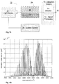
- Figs. 1B , 1C and 1D show a graph of the absorption cross section of CO 2 at ambient conditions (namely pressure of 1 atmosphere and temperature of 25°C) as a function of wave number (taken from HITRAN database), and Figs. 1C and 1D show in more details a part of this absorption cross section of CO 2 superposed with two examples of spectral emission profile of the light source for the first and second wavelengths produced by a QCL light source. These profiles correspond to substantially monochromatic light beams of first and second narrow wavelength spectra.
- Fig. 1B shows a graph of the absorption cross section of CO 2 at ambient conditions (namely pressure of 1 atmosphere and temperature of 25°C) as a function of wave number (taken from HITRAN database)
- Figs. 1C and 1D show in more details a part of this absorption cross section of CO 2 superposed with two examples of spectral emission profile of the light source for the first and second wavelengths produced by a QCL light source.
- FIG. 1C the emission profile of the light source for the first and second wavelengths respectively, overlap/cover an absorption peak (absorption line) of the CO 2 and overlap/cover an absorption valley (transmission line) of CO 2 in the mid-IR spectrum near 4.3 microns.
- Fig. 1D as in Fig. 1C the emission profile of the first wavelength, overlaps an absorption line of the metabolic gas, while the second wavelength is located outside a spectral range of intense absorption lines of the metabolic gas.
- Fig. 1B shows the features of the CO2 absorption spectrum in wave-number range of near about 2300 to 2380 cm -1 (i.e. for mid-IR wavelength range of about 4.2 to 4.35 microns).
- Fig. 1C shows in more details the absorption spectrum (graph G CO2 ) of CO2 in the wave-number range of about 2359 to 2364 cm -1 (i.e. for wavelengths ranging between 4.230 to 4.239 microns) and illustrates the typical width of CO2 absorption lines of about 0.07 cm -1 (namely in the order of about 0.15 nm in that wavelength range).
- Figs. 1C and 1D present narrow spectral profile (graphs G 1 in these figures) of a first light beam (first type wavelength) produced by a tunable QCL light source 12 used in some embodiments of the present invention.
- FWHM full-width-half-maximum
- the second wavelenth presented by graph G 1 was tuned to central wavenumber of 2362 cm -1 (wavelength of about 4233,7 nm) which is in the middle between the two absorption lines of the metabolic gas.
- the CO 2 absorption at the second wavenumber will be much lower, than at the first one.
- the second wavelength presented by graph G 2 was tuned to central wavenumber of 2385 cm -1 (4192,9 nm). Therefore in this example the second wavenumber is outside the spectral range/band of high absorbance by the metabolic gas (e.g. outside the so called 4,3 micron absorbance band of CO 2 at which main CO 2 absorption lines are present). Accordingly the CO 2 absorption at 2385 cm -1 wavenumber is much lower, than its absorbance at both at the 2361,4 cm -1 and 2362 cm -1 wave-numbers.
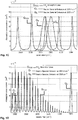
- the transmittance of CO 2 for the above exemplified wave-numbers of the first and second type wavelengths is illustrated in logarithmic scale in Fig. 1E for various concentrations of the metabolic gas CO 2 .
- the transmittance was simulated for a container with transparent walls filled with mixed N 2 and CO 2 gases at different CO2 concentrations, at normal pressure, normal/room temperature of 300 K, and with optical absorption path of 8 cm.
- the transmission of the first type wavelength (graph G 1 in Figs. 1C and 1D corresponding to wave-number 2361.4 cm-1) is illustrated in graph T1.
- the transmission of the second type wavelengths (graphs G 2 in Figs.
- Fig. 1F shows in self explanatory manner the transmittance ratios T1/T3 and T2/T3. These ratios are monotonically decreasing functions in both cases. Accordingly in some embodiments of the present invention it may be sufficient to measure the CO 2 absorbance to obtain the value of one such ratio which is sufficient to for unambiguous determination of the CO 2 concentration in the container. However, in some embodiments of the present invention the reliability of the measurements are further improved by utilizing more than two wavelengths (e.g. to obtain more than one such ratio). That is especially relevant for high concentrations of CO 2 gas (exceeding few per cent level) where absorption at certain wavelengths could be very strong and measured signal very weak.
- the controller operates/tunes the light source to emit light in the first substantially monochromatic wavelength(s) (e.g. as illustrated in graph G1 ) corresponding and overlapping/covering the high absorbance peaks/lines of the metabolic gas such as those of CO2 illustrated in the figure, thereby providing accurate measurement of the CO2 absorbance. Additionally, as noted above, the controller operates/tunes the light source to emit light in second substantially monochromatic wavelength(s) (e.g. as illustrated in graphs G2 of Figs. 1C and 1D ) corresponding to regions/valleys of low absorbance of the metabolic gas (e.g.
- These second monochromatic wavelength(s), while being narrow and tuned so as to substantially not overlap with the absorption lines are provided for reference to the absorption of materials in the optical path other than the probed metabolic gas.
- these second wavelengths are in the general neighborhood/band of the first wavelengths such that they provide reference data being indicative, with good accuracy, of the absorption of the first optical wavelength(s) in the optical path, in case the probed metabolic gas was absent there.
- the second predetermined wavelength is selected such that measured data of the transmission thereof provides reference indicative to the optical absorbance of the first wavelength by materials other than the metabolic gas.
- a spectral distance between a "first type" wavelength of the emitted light and a "second type” wavelength serving for the reference measurement (to which the metabolic gas is substantially transmitting) is in the order of 0.5 cm -1 -0.75 cm -1 that corresponds to the half of distance between two absorption lines of CO2 gas.
- the separation distance can be of order 30 cm -1 for the second absorption line to be outside the whole spectral range with intense absorption lines.
- this wavelength could be used as reference wavelength transmittance of light beam at this wavelength does not depends on the concentration of CO2, but rather reflects absorptions of the light beam on other optical components such as container walls transmittance.
- the spectral distance between the first and second wavelengths is substantially small such that the first and second wavelengths are characterized by same or similar transmission through predetermined/conventional materials used for conventional containers of biological material.
- first type wavelength(s) for the measurement of absorbance by the metabolic gas and the second type wavelength(s) close thereto for reference measurements allow to detect small/minute changes in the metabolic gas concentration with high sensitivity and accuracy. For example changes of 10 ppm or 0.001% in the gas concentration can be detected even in relatively noisy environments in which various other materials such as those of the walls of the storage-bag and/or fermentation container and/or vapors (e.g. water vapors) are located in the region of interest. The effects of the later can be discarded with accuracy based on the reference measurements of the second wavelengths being close to the first wavelengths.
- the technique of the present invention is employed to measure metabolic gas concentrations in conventional containers such as conventional storage bags/vials for platelets. This is achieved by taking advantage of the above described technique utilizing the "first type” and “second type” (measurement and reference wavelengths) in the spectroscopic measurements.
- the detection of various microorganisms in-situ in such conventional and generally arbitrary containers is made possible although the materials of the container is not a-priory known, and although the container's materials may include materials such as polymers and/or other materials, which may be relatively opaque to the IR wavelengths used by the system of the invention (e.g. opaque to wavelengths in the mid-IR).
- the detection module 15 includes an electronic signal processor/lock-in amplifier 13 that receives the signal from the IR detector 14.
- the lock-in amplifier enables to even further improve the signal to noise ratio (SNR) provided by the system thus further improving the sensitivity and accuracy of the measurements relating to the concentration(s) of metabolic gases and consequently detection of microorganisms.
- the control system 30 is adapted for operating the tunable broadband IR light source 12 for applying time modulation to intensity of light emitted in one or more (e.g. in each) of the at least two (first and second) wavelengths, and also operating the lock-in amplifier 13 to determine/measure the detected intensity(ies) of the emitted light with high accuracy based on that modulation.
- transmittance of the region of interest to the first and second wavelengths can be determined with high accuracy based on the intensity modulation, while noise is mostly discarded as it is generally not modulated in the same way.
- configuration and operation of various lock-in amplifiers are generally known in the art of signal processing and are therefore not specifically described herein. A person versed in this art would readily appreciate the various possible configurations of such lock-in amplifier with appropriate modulation to the emitted illumination to be used in the system of the invention.
- the system 10 is configured and operable for utilizing its ability to accurately detect small changes in the metabolic gas concentration, for operation in-situ and/or in real time to non-invasively detect microorganisms in the containers/bags permeable to the metabolic gas and/or in association with one or more openings (inlets/outlets) through which in/out flow of gases may occur.
- the controller 30 is adapted for further processing the concentration of metabolic gas to detect microorganisms in the biological material 26.
- the detection is merely qualitative to identify whether significant levels/amounts of such microorganisms exist in the biological material 26. In other cases, the detection is qualitative and is aimed at estimating the levels (e.g. amounts/concentrations) of the microorganisms in the biological material 26.
- the system is adapted/configured for operating in closed containers, sealed and non-permeable to the probed metabolic gas(es).
- the concentration of the metabolic gas in the container is a function of the time the container is sealed and the amount of microorganisms therein during that time.
- the concentration of CO2 is increasing function with time as long as there is biological activity inside of container responsible for CO2 emission.
- the concentration of living cells in that case depends on the growth history of the cells from the beginning of incubation.
- the correspondence between the number of cells and measured CO2 concentration could be find out in that case by computing rate of changes of CO2 concentration and correlating it with respiration rate of a single cells and the number of cells.
- the container is not sealed with respect to the metabolic gas.
- the present invention allows for detecting microorganisms also in such containers in-situ and in real time without taking and sealing a sample of biological material from the containers and without incubating the sample (i.e. non-invasive detection). This is performed by taking advantage of the high sensitivity and accuracy of the technique of the invention for detecting small changes in the metabolic gas concentration.
- the controller 30 system may operate to measure the metabolic gas concentration in a dead space associated with the container of biological material, while the dead space is non sealed to the metabolic gas, and to utilize the measured concentration of the metabolic gas to detect the microorganisms qualitatively and/or qualitatively based on an equilibrium condition (e.g. balance/difference) between a rate of escape/flow of the metabolic gas from/into the container and a rate of generation or consumption of the metabolic gas by the microorganisms.
- an equilibrium condition e.g. balance/difference
- processing may be performed by computing/estimating the microorganisms level in the biological martial 26 based on the measured concentration of the metabolic gas diffusion of that gas through walls of the container 24.
- the container may be a conventional storage container for platelets or other blood components.
- the system 10 of the invention allows real-time in- situ detection of microorganisms in biological material 26 contained in fermentation container 24 (e.g. in a container of a fermentation system).
- the controller 30 may be configured and operable to determine the level of microorganisms based on the equilibrium condition (e.g. balance/difference) between the rate of escape/flow of the metabolic gas from/into the container 24 through an outlet thereof, and a rate of generation or consumption of the metabolic gas by the microorganisms.
- the equilibrium condition e.g. balance/difference
- concentrations of the metabolic gas in a gas inlet to the container 24 e.g.
- the concentration in the external atmosphere and a concentration of that metabolic gas in the atmosphere in the dead space 28 of the container, which may be a dead space of the container itself (e.g. above the biological material 26 ) or a dead space in fluid communication therewith, for example located at a gas outlet of the container.
- the difference in the metabolic gas concentrations corresponds to the amount of microorganisms in the container. More particularly, this is the difference that may be computed from the difference in the amount of metabolic gas flowing in and out of the container (e.g. computed by the controller 30 as the difference between the products of the flow rates in the gas inlet and outlets multiplied by the metabolic gas concentration thereat respectively).
- the controller 30 may utilize predetermined data of the concentration of the probed metabolic gas in the gas inlet (e.g. in the external atmosphere of the container. Also the spectroscopic/optical measurements may be applied to a region of interest associated with the cavity/dead-space of the container itself and/or at a gas outlet from the container.
- the light source 12 and the detector 14 may be optically coupled to one or more optical windows exposing the dead-space to be inspected (e.g. optical windows coupled to the fermentation container and/or to gas outlet).
- the controller 30 may be adapted to apply continuous/periodic detection of microorganisms and/or their level in the fermentation container.
- the controller 30 may be adapted to repeatedly operate the optical system in the manner described above to obtain, in real time, and/or repeatedly within predetermined time intervals, data indicative of the metabolic gas concentration in the container and/or in its outlet. Repeatedly/continuously obtaining such gas concentration during a period of time provides indication to the amount of microorganisms in the container as a function of time and/or indication to the change/rate of change in this amount.
- the controller may be adapted to process the data indicative of the amount of microorganisms, or the change thereof, as function of time for monitoring and/or controlling the fermentation process occurring in the container.
- reference data/model relating to the fermentation process in a container may be utilized by the controller to determine actions/operations to be carried out for controlling the fermentation (e.g. stopping the fermentation and/or changing some of the fermentation conditions such as temperature and/or other conditions).
- This reference data may for example be stored in the form of a lookup table (LUT) and/or a set of one or more functions/models relating to the amount of micro-organisms and/or rate of change in their amount with certain actions to be carried out and/or certain fermentation conditions to be applied/maintained.
- LUT lookup table
- the fermentation process monitoring/controlling can be realized using the a model (e.g. mathematical-model/formula and/or data) relating the amount of biomass in the fermentor with measured concentration of CO2.
- the model may be pre-determined and predefined in advance and loaded to memory and/or other storage device of the controller 30 in the form of data/LUT and/or as a set of instructions soft/hard coded.
- Such a model relating the amount of biomass in fermentor with the concentration of CO 2 may be obtained/determined in advance by utilizing various techniques.
- the amount of biomass may be measured by optical density techniques (OD) and/or viable counts and/or other run parameters such as pH, RPM, TEMP, and the total volume (TV) of the metabolic gas CO 2 emitted/consumed by the microorganisms from the beginning of the run (seeding time).
- OD optical density techniques
- viable counts such as pH, RPM, TEMP, and the total volume (TV) of the metabolic gas CO 2 emitted/consumed by the microorganisms from the beginning of the run (seeding time).
- the model may be a mathematical model based for example on multivariable robust regression analysis. Verification of the mathematical model may be performed by number of fermentation processes performed under same conditions, which are optimal for the high product yield in the batch fermentor.
- a RUN protocol such as executable instructions and/or LUT, is then used by the controller 30 for estimating, the amount of biomass in the fermentor based on the model's parameters and the real-time measured concentration of CO2 gas and possibly other run parameters.
- the RUN protocol is based on estimated values of the biomass and may include data indicative of different aspects/actions to be taken during the monitoring of the fermentation process (e.g. conditions for adding nutrients for cell in fermentation, determining optimal inducing time (for recombinant protein production) and harvesting time, controlling pH level and other run aspects.
- the bacterial growth will be reflected in real time in changes in the metabolic gas concentration.
- the carbon dioxide concentration will be substantially equal to equilibrate with that in the air outside the storage tank.
- the concentration of metabolic gases inside a gas permeable container is determined by equilibrium conditions between release and rate of diffusion of metabolic gases through the walls of the container.
- containers permeable to the metabolic gas(es) are considered as an example of not-sealed containers with respect to the metabolic gas(es).
- such permeability and diffusion of the gas from and into the container is exemplified as relating to the permeability of the container's walls.
- the technique described below is applicable to any other type of containers no sealed with respect to metabolic gases, wherein the flow in and out of the container may be additionally or alternatively through gas inlets and/or outlets of the container.
- N CO 2 is the number of CO 2 gas molecules
- J is the diffusion flux from the walls of the container
- A is the surface of the walls exposed to the gas exchange
- W is the source term that describe total rate of CO 2 production inside the container.
- N bact is the number of bacteria inside the container
- r bact is CO 2 emission rate by bacteria in units m 3 /sec
- W 0 is the product CO 2 emission rate.
- N bact 1 r bact n in ⁇ i out KA ⁇ W 0
- the number of bacteria is proportional to the change of CO 2 concentration ⁇ n CO 2 , to the container wall permeability coefficient K and to the container wall area A, and is inversely proportional to the CO2 emission rate by a single bacteria r bact .
- N CO 2 is increasing with time as long as there is biological activity inside the container responsible for CO2 emission.
- the equation (7) provides means for detecting biological activity in a product stored in gas permeable container.
- the procedure is especially simple if the only source for emission of CO2 gas inside the container is bacteria.
- increase of concentration ⁇ n CO 2 above the ambient will indicate on presence of biological activity inside the container.
- detection of bacterial contamination can be done by measuring change ⁇ n CO 2 of CO2 concentration relative to some reference concentration of uncontaminated product.
- the change of concentration ⁇ n CO2 can be measured by means of IR absorption of beam of tunable IR light source such as Quantum Cascade Laser directed through the container walls.
- tunable IR light source such as Quantum Cascade Laser directed through the container walls.
- %CO2 level The dependence of %CO2 level on the increase of bacterial contamination was studied experimentally.
- Staphylococcus epidermidis obtained from the American Type Culture Collection (ATCC) were used to contaminate a bag of platelets that were collected from a single donorby apheresis.
- the bacterially inoculated apheresis platelets were agitated at 22°C and measurements were performed using QCL spectroscopy.
- the platelet container was measured before and during bacterial contamination. Samples were taken from the contaminated platelet bag and a standard culture plate count was used for determining bacterial concentration [colony forming unit (CFU)/mL] in the platelet medium.
- CFU colony forming unit
- Fig. 3 is a plot of %CO2 vs. bacterial concentration.
- the bacterial concentration that was measured at the point where %CO2 started to rise was between 1*10 6 CFU/mL to 6*10 6 CFU/mL.
- the Y-axis shows %CO2 level and the X-axis shows bacterial concentration measured using standard titration analysis.
- system 10 of the present invention may be used for measuring the concentration of carbon dioxide in the dead space 28 above the platelets 26 in a gas-permeable bag 24 that has been removed temporarily from storage and agitation for the purpose of measuring the concentration of carbon dioxide in dead space 28.
- the tunable infrared laser 12 for example a QCL
- an infrared detector 14 are positioned so that the light beam 20 from laser 12 is aimed at detector 14.
- the light beam 20 is focused on detector 14 by a calcium fluoride lens 18.
- Bag 24 is positioned between laser 12 and detector 14 so that light beam 20 traverses dead space 28.
- Controller 30 tunes laser 12 to emit light beam 20 at selected wavelengths in the vicinity of 4.3 microns at a pulse repetition rate of 5 KHz, receive the corresponding response signals from detector 14, and analyze those signals to estimate the concentration of carbon dioxide in dead space 28.
- the signal reception and analysis portion of the controller 30 may be implemented by a lock-in amplifier that locks onto the 5 KHz signal from detector 14 and displays the amplitude and phase of that signal.
- the path length of light beam 20 across the interior of bag 24 is preferably at least several centimeters.
- a sufficiently long optical path through bag 24 may not be available, and/or the walls of bag 24 may not be sufficiently transparent at the relevant wavelengths to allow an accurate measurement of the concentration of carbon dioxide in dead space 28.
- FIGs. 2A and 2B illustrating two modified configurations of system 10 that deal with these problems.
- System 10 is configured generally similar to that of Figs. 1A .
- the bag 24 may be held in place by two vertical walls 16.
- a separate closed e.g.
- cylindrical gas chamber (pipe/reservoir) 40 is used and is connected to the bag 24 using a connecting tube 50 which is by its one end connected by fusion with a heating instrument to the bag, as is routinely done to platelet bags in blood banks, for various reasons of their own. Such procedures are performed routinely without damaging the platelet bags or introducing contamination.
- the other end of the connecting tube 50 is connected to the chamber 40 that is at least partially transparent in at least a portion thereof to the relevant wavelengths and that is sufficiently rigid and long enough to provide a predetermined fixed optical path (e.g. of several centimeters) for light beam 20.
- a filter 52 is used in tube 50, that is permeable to gases but not to liquids, and thus keeps liquids from bag 24 out of reservoir 40 but allows the gaseous contents of reservoir 40 to equilibrate with the gaseous contents of dead space 28 in the bag 24 so that the concentration of carbon dioxide in reservoir 40 is substantially identical to the concentration of carbon dioxide in dead space 28.
- the equilibration of the concentration of carbon dioxide between reservoir 40 and dead space 28 occurs sufficiently fast such that no special steps are needed to hasten this equilibration.
- the interior of reservoir 40 is an extension of dead space 28.
- Such connection to the separate gas chamber may be used in case the required optical path (for detection of the specific metabolic gas) inside the container is unavailable and/or in case the container's walls totally block the IR radiation.
- the controller 30 for accurate, in-situ real time determination of the metabolic gas(es) concentration.
- IR transmission through the dead space in two or more wavelengths (comprising the above described first and second wavelengths) is measured as described above.
- the measured data is processed by the controller 30 for example by utilizing an absorption model of the at least one metabolic gas. To this end, a best fit between intensity values obtained from the absorption model and the measured intensity values is performed to thereby determine the concentration of the at least one metabolic gas.
- I 0 is the laser intensity
- ⁇ is the total intensity loss that are not related to optical gas absorption
- ⁇ ⁇ is the absorption coefficient (in cm -1 ) at the given wavelength of the light ⁇
- c is the probed gas concentration (by volume) inside the container
- c 0 is the concentration of the probed gas outside the container in the atmosphere
- l is the pathlength inside the container
- l 0 is the pathlength outside the container between IR source and detector
- f ( ⁇ - ⁇ 0 ) is the laser spectral distribution function around the central wavelength ⁇ 0 .
- the integration limits ⁇ min and ⁇ max with ⁇ min ⁇ ⁇ 0 ⁇ ⁇ max are assumed to be such that f ( ⁇ ) is nearly zero outside the integration domain.
- the signal on the detector is assumed to be proportional to the transmittance intensity.
- the central wavelength can be changed within certain range.
- x cl and b is a constant
- x (and therefore c ) can be found from equation (11) if the measurement is done at two or more wavelengths of light ⁇ i .
- the unknown constant b can be excluded from the set of equations.
- Fig. 4 shows simulated absorption versus wavelength and CO2 concentrations of the beam of the QCL calculated using equation (9) in the IR spectral range 2355 cm -1 -2410 cm -1 .
- the graphs H 1 , H 2 , H 3 and H 4 correspond to the absorbed intensities for respectively 4%, 1%, 0.08% and 0% of the CO2 concentration. As shown, the graphs have smooth behavior of the spectra on wavelength and the transmittance increases when light frequency changes from 2360 cm -1 -2410 cm -1
- Figs. 5A and 5B showing experimental set ups of the system of the present invention for detection of metabolic CO2 inside a platelets product in a plastic bag utilizing respectively direct measurement through the bag containing the platelets ( Fig. 5A ) and utilizing a separate gas chamber connected to the platelets container ( Fig. 5B ).
- the set up utilizes tunable QCL, IR detector (e.g. equipped with a CaF2 plano-convex lens), lock-in amplifier detector and a controller.
- the QCL operates in the pulse mode with repetition frequency of 5 kHz and pulse width 500 nsec.
- the tunability range of the QCL includes the measurement range that was from 2361.4 cm -1 till 2391cm -1 .
- the concentration c of CO2 gas inside the container is estimated using equation (12) for different ⁇ i using the nonlinear minimization of the function s ( x ).
- the monitoring and controlling of the fermentation may be based on a model such as formula and/or reference data relating various parameters of the fermentation including metabolic gas concentration with an estimation of the biomass (i.e. it amount) in the fermentation.
- a Linear Regression Model is used for estimating the biomass during the fermentation process.
- the regression model may be pre-computed model calculated utilizing statistical regression analysis for modeling the relationship between one or more parameters, also considered as to as predictor x and/or regressor variable(s), and one or more other parameters, also referred to as response variable(s) y .
- the regressor/predictor variable(s) (generally denoted herein x i ) include the concentration C of CO 2 measured in the gases emitted from the fermenter, and/or TV being the Total Volume of CO2 emitted from the beginning of the run (seeding time).
- the response variable (generally denoted herein y) may include the optical density OD of the biological material in the container and / or the viable count VC (namely a measure of the count of microorganisms as typically obtained via microscope count).
- y ⁇ 0 + ⁇ 1 x 1 + ⁇ 2 x 2 + ⁇ ⁇ k x k + ⁇
- x i the regressor/predictor variable(s) (e.g. parameters of the fermentation process which are independent from the response variable (OD in this case))
- ⁇ is the random components with supposed mean zero and variance ⁇ 2 .
- the regressor/predictor variable(s) x i may be measured in real-time during the fermentation process (e.g. without sampling/extracting the material from fermentor and probing).
- TV (t) (in liters) is the total volume of CO2 gas emitted by the species since the beginning of the run (from the beginning of the fermentation process)
- rate is the aeration rate (e.g. measured in liters/min
- c(t) is the concentration of CO2 (in volume fraction) measured in emission gases from fermentor.
- the CO2 concentration predictor parameter c(t) in addition to the CO2 concentration predictor parameter c(t), in some cases other run/predictor parameters/variable(s), may also be measured (e.g. continuously) to provide estimation of the response parameter(s) y with improved accuracy.
- the generalized formula (13) above may be used as a model defining the relation between the predictor parameters measured/considered x i and the response parameters y .
- the predictor parameters x i may include:
- Fig. 6A is a table illustrating several of the above predictor parameters measured/obtained during an experiment of a fermentation process/run of recombinant protein production utilizing Escherichia coli E.Coli fermentation.
- the recombinant proteins are widely used in biotechnology and medical applications as vaccines and protein therapeutics, and as industrial enzymes for detergents and fuel ethanol production.
- Such recombinant protein products are made by inserting the gene that encodes the desired protein into a host cell (bacteria, yeast, insect, or animal cells) capable of producing this protein.
- Fig. 6B shows graphs OD g and TV g illustrating respectively the measured optical density - OD and the total volume of CO 2 emission-TV, as a function of time.
- OD and TV were measured during a fermentation experiment. As shown the OD is increased from 1 to about 55 during the first 10 hours of the experiment. Then it gradually continues to grow up to values of 75 during the next 12 hours of experiment. TV was measured continuously while OD at 15 time points as specified in the table in Fig. 6A . The correlation coefficient between OD and TV is 94.4%.
- Fig. 6C is a graphical illustration showing two regression and reference plots, RG and RF, corresponding to the optical density of a biological material as a function of time.
- Plot RF is a reference plot obtained by direct measurements of the optical density taken during the experimental fermentation run.
- the regression plot RG is obtained during the experimental fermentation run by processing the measured CO 2 concentration based on the regression model which is used according to the present invention. As shown in the graphs the OD results obtained by the regression model based on the CO 2 concentrations are similar and almost same as those obtained by direct OD measurements.
- the parameters of the regression model are estimated by means of the robust regression algorithm based on equations 13 and 14 as described above. More specifically, the robust regression operates by assigning a weight to each data point. Weighting is done automatically and iteratively using a process known as iteratively reweighted least squares. In the first iteration, each point is assigned equal weight and model coefficients ( ⁇ i in equation 13 above) are estimated using ordinary least squares. At subsequent iterations, weights are recomputed, so that points, which were farther from model predictions in the previous iteration, are given lower weight. The model coefficients are then recomputed using weighted least squares. The process continues until the values of the coefficient estimates converge within a specified tolerance.
- the regression model used in this experiment utilizes the following regression coefficients ⁇ i between response variable OD ( y in equation 13 above) and the regressor/predictor variables (x i in equation (13) above) including: C, TV, RPM, pH and TEMP.
- Fig. 6D shows the experimental results for a measured plot PI of CO 2 concentration (left y axis) and the plot P2 of OD (right y axis) as a function of time. As shown in the figure there is a correlation between the OD and CO 2 measurements through during first 325 minutes of the experiment. Then, due to stress in carbon source, the bacteria/microorganisms keep growing with alternative metabolic cycles, as seen in CO 2 concentration plot P1. When the biomass/microorganisms die, the CO 2 decreases while the OD parameter stays constant.
- the present invention provides an effective and simple technique for accurate in-situ real time non-invasive monitoring of a biological material by monitoring metabolic gases in the dead space associated with the biological material.
- the biological material that can be monitored/inspected utilizing the invention includes but is not limited to sugars, proteins, or nucleic acids, or a combination of these substances. They may also be living entities, such as cells and tissues. They may be made from a variety of natural resources - human, animal, and microorganism-and may be produced by biotechnology methods.
- Example of biological product is blood transfusion products such as RBC, platelets and plasma.
- the biological materials may include food product (food microbiology products).
- Bacterial viability determination is one of the major concerns in the food industry because injured bacteria cause a significant health threat if they revive during food distribution and storage and it is important to examine the efficacy of various intervention treatments used in food processing. Also, the invention provides for effective monitoring of a fermentation process, where micro-organisms are exploited to produce a wide variety of products such as dairy products (cheese, yogurt), beverages (beer, wine), single cell proteins (SCP), antibiotics, chemicals (citric and acetic acid, amino acids, enzymes, vitamins), fuels (ethanol, methanol, methane).
- dairy products cheese, yogurt
- beverages beer, wine
- SCP single cell proteins
- antibiotics chemicals
- chemicals citric and acetic acid, amino acids, enzymes, vitamins
- fuels ethanol, methanol, methane
Description
- The present invention relates to a method for measuring the concentrations of at least one metabolic gas and system for use in detection of micro organisms or living cells.
- Monitoring the live biological activity in a biological material is needed in various industries, for example in the medical field for monitoring microorganisms contaminants in blood/blood-components, in food and beverages (F&B) industries, and in pharmaceutical industries for example for monitoring fermentation processes.
- The conventional techniques for monitoring a biological activity in a biological material generally include direct techniques such as: viable count in which a diluted samples are grown on agar medium dish; staining or microscopy; pH and glucose measurements; swirling; and optical density (OD) measurements in which a sample of the biological material taken in to a cuvette and the level of microorganisms is determined optically based on turbidity of the sampled biological material itself. Other known techniques utilize monitoring the biological activity indirectly, for example based on analysis of gases consumption (such as dissolved oxygen - d02) or accumulated (such as carbon dioxide - CO2) in a sample of the biological material. In those techniques, a sample of the biological material is incubated for a period of time to allow consumption or accumulation of gases by live microorganisms contained in the sample and then the metabolic gases are analyzed chemically and/or by utilizing spectroscopic measurements.
- Document
US 5 155 019 A discloses a non-invasive real time system for detection of the presence of biological activity in a sealed container utilizing IR analysis of carbon dioxide with high sensitivity that can reflect biomass and biological processes state. - Document
US 4 889 992 A discloses a system for non invasively and real time detecting microorganisms in culture media by means of measurement of gaseous metabolic products, wherein carbon dioxide is measured by specific IR spectroscopy in a zone of the container separated from the culture medium but still in fluidic communication with it. - For example Sussman et al.,
US 5,155,019 , test for the presence of microorganisms in a possibly contaminated substance by inspecting a sample of the substance. The sample of the substance is transferred to a sterile culture vial that includes a growth medium for the microorganisms, the sample, medium and gas within the head space of the vial are sealed the vial is incubated, and infrared spectroscopy is used to monitor the concentration of carbon dioxide in the head space above the growth medium in the vial. The vial is positioned between a source of a beam of infrared radiation and a detector of the beam so that the beam traverses the head space. - Berndt,
US 5,482,842 , teaches a similar method, but uses two sources and two detectors. Bachur et al.,EP 1 724 335 , teach a similar method that uses one or more tunable lasers as the infrared source(s). Hoberman,US 4,889,992 , teaches a vial that is adapted for use in such methods: the vial includes a passive mechanism for keeping liquid and foam from the growth medium out of the path of the infrared beam. - There is a need in the art for a novel technique for in-situ real-time and noninvasive monitoring of biological materials, enabling detection of microorganisms in a biological material, such as blood components, food products and/or biological materials used in fermentation processes, for example used in the pharmaceutical and/or food and beverages (F&B) industry. Specifically there is a need in the art for an in-situ real time technique for detection of microorganisms in a culture media utilizing measurement of gaseous products generated during bacterial proliferation.
- The known techniques for detecting microorganisms in biological material by spectroscopic measurements of metabolic gas concentrations are generally not suited and/or are in-capable of in-situ real time operation. This is mainly because these techniques are invasive with respect to stored biological material that has to be inspected, i.e. they require sampling and incubation of the biological material in a separate sealed incubation container (sampling vial) which is impermeable for gases and possibly contains certain growth media. To this end, the conventional techniques utilize sampling/transferring certain amount of the biological material from a sealed container in which it is stored/maintained into a suitable sampling vial/container, which is specifically designed/selected to facilitate the spectroscopic measurements of metabolic gas(es). Conventional sampling vials used for this purpose are generally non-permeable to the metabolic gas in order to enable accumulation of high concentrations of the gas in the sampling vial. The conventional sampling vials are also specifically configured for the spectroscopic measurements (e.g. formed with specifically selected materials having high transitivity to wavelengths used in measurements). The sampled biological material is maintained in the sampling vial for sufficient time (the detection limit is only after incubation time of between18 to 48 hours) for consumption or accumulation of relatively low or high concentrations, respectively, of gas consumed or accumulated by microorganisms contained in the biological material. As indicated above, many of the known techniques of the kind specified use incubation of a test sample while providing suitable growth conditions (e.g. providing growth medium such as agar, and/or incubating conditions/temperatures, and/or sufficient time for growth) to accelerate the microorganisms growth and accordingly accelerate production of the metabolic gases by the microorganisms contained in the sample. This is in fact because the sensitivity and/or accuracy of the known spectroscopic metabolic gas detection techniques require consumption or accumulation of relatively low or high concentrations, respectively, of the gas for the detection thereof.
- The known techniques are thus not suited for in-situ real time non-invasive monitoring of biological activity/microorganisms in a biological material mainly because (1) they are invasive, i.e. require sampling of the biological material, (2) require specific equipment, i.e. the sampled biological material is transferred into a separate, specifically designed, sealed sampling vial (e.g. non-permeable to metabolic gases, highly transmitting for wavelengths used in spectroscopic measurements, e.g. containers made of glass/quartz), as well as typically require use of specific growth media, and (3) they are time consuming as they typically require relatively long incubation periods (e.g. 18-48 hours) of the sampled biological material for accumulation of sufficient (measurable/detectable) concentrations of the metabolic gases. Non-invasive gas monitoring methods available are not sensitive enough. However, in-situ, real time and non-invasive high resolution monitoring of biological activity in biological substances are needed in various fields. Specifically, such traits are needed in medical fields for handling blood and blood components for monitoring the blood/components thereof (e.g. prior to blood transfusions). Also such traits are highly needed in various fermentation processes in which sensitive, real-time monitoring of the biological activity may provide substantial increase in the yield of the fermentation process. This allows to control the growth of cells of a wide variety of microorganisms, early stage detection of cell growth, shorter R&D cycle time, provides for real time monitoring of biomass production process for increasing the yield (e.g. by determining optimal seed transfer and induction times, controlling the growth-media/biological-material composition utilizing controlled-depletion of nutrients, etc).
- The present invention allows for in-situ non-invasive (without opening the container and withdrawing a portion of the biological material) real time and sensitive monitoring of a biological material, such as (but not limited to) a blood component, that can serve, intentionally or unintentionally, as a growth medium for the growth of microorganisms such as bacteria, and that is contained within a container sealed with respect to the biological material. Described is a method and device for monitoring any biological material, such as food, human or animal tissues, and cell cultures, with particular application to blood components such as platelets. The technique of the present invention allows for detecting bacterial contamination in platelets contained/stored in conventional platelet storage bags (e.g. plastic bags) based on quantitative analysis of metabolic gases, such as CO2, released by bacteria inside the platelet plastic storage bag which is permeable to metabolic gases, while the plastic storage bag with the platelets remains sealed to contaminates.
- The concentration of the metabolic gas in a dead space associated with the storage bag is monitored by optical/spectroscopic measurements performed according to the technique of the present invention as described in more details below. The dead space, for the purposes of the invention, is a space/region which is free of the biological material under inspection and is in fluid communication therewith. In some embodiments, the dead space is defined by a region/portion of the container above a portion thereof containing the biological material. In some other embodiments, the dead space is defined by a gas chamber/reservoir/pipe connectable to the container (e.g. in a manner maintaining the sealing of the container), so as to be in the fluid communication with biological material in the container. Such reservoir/pipe may be formed by a separate cavity configured as an extension of the dead space in the container.
- The measurements of metabolic gas concentration may for example utilize spectroscopic measurements in mid-IR spectrum of light at wavelength(s) overlapping with strong absorption line(s) of a metabolic gas (e.g. CO2 or other metabolic gases). The light is transmitted through a part (dead space) of the plastic bag that is above the stored platelets, and is appropriately detected by an IR detector. The spectroscopic technique of the invention provides for determining the concentration of CO2 or other metabolic gas by measuring light absorption within the plastic bag, while allows for discarding/discriminating the absorbance of the plastic bag itself, thus enabling in-situ monitoring of the metabolic gases contained in the dead space of the bag.
- The technique allows the detection of different transfusion-relevant contaminating bacterial species. This approach provides on-line measurement of respiratory gases such as CO2 at ambient atmospheric concentrations without the need for any pre-concentration or gas separation. The method is non-invasive since it does not require opening the plastic platelet bag for examination. This non-invasive bacterial detection method represents a new approach to prevent the transmission of bacterial contamination of platelets with an advantage of the method is that all measurements can be performed in real time, until right up to the time of transfusion and therefore the risk for sample errors is reduced to a minimum and the platelets' storage time is extended. Also, unlike conventional methods, the method of the present invention can be used with containers that are sealed with respect to the biological fluid, and are either impermeable or are permeable to the metabolic gas(es) being monitored. The invention includes real-time, precise monitoring of fermentation processes. In fermentation, the biological material generally added to the growth medium. Specifically for example, fermentation processes are used in the pharmaceutical industry for generating various biological substances such as: microbial cells (such as E. coli); microbial enzymes (catalase, amylase, protease, etc); primary metabolites (ethanol, citric acid, glutamic acid, etc); secondary metabolites (antibiotic, recombinant products: insulin, hepatitis B vaccine, interferon, etc).
- The technique of the invention allows the detection of different microorganism's species including: aerobic & anaerobic; transparent & non-transparent; and pathogenic microorganisms. This approach provides on-line high resolution measurement of respiratory gases such as CO2 at ambient atmospheric concentrations without the need for any incubation or gas separation. The detection method and system of the invention can apply qualitative and/or quantitative analysis and estimation of a level of biological activity of microorganisms, for example in agar plates, and monitoring of biological activity such as in the case of measuring bacterial growth in the bacterial production of pharmaceutical proteins. Microorganisms are used commercially to produce foods (such as vinegar, yogurt, cause beer and wine spoilage), antibiotics and chemicals such as ethanol. Production of some of the most important and complex pharmaceuticals such as insulin, hormones and antibodies is carried out using microorganisms (such as E. coli) that have been modified genetically using recombinant DNA technology. From the early stages of commercial production of recombinant proteins, the handling of recombinant cultures has been subject to challenges. One of these challenges is how to cope with the problem of instability in recombinant organisms and induction. Commercial production of products on a large scale, especially in the pharmaceutical industry using fermenters, depends heavily on the stable maintenance of the organisms. The fermentation process of recombinant bacteria needs to be precise and the bacteria concentration has to be monitored.
- For clarity, in the following description, monitoring of pharmaceutical fermentation processes for generating proteins, is specifically described. However it should be understood that the present invention can be used for real time monitoring of other fermentation processes in the pharmaceutical industry and/or in the F&B industries.
- In fermentation, specific microorganism species are deliberately introduced into a fermentation container containing a biological material serving as growth medium. The fermentation container is kept at suitable conditions (e.g. glucose, yeast, agitation, temperature) encouraging the production of the desired biological substances/proteins by the induced microorganism species. Typically, a gas inlet is coupled to a fermentation container to supply suitable atmospheric conditions for the microorganisms' metabolism (e.g. supply of ambient air) and a gas outlet is also coupled to the fermentation container to evacuate gas which is richer in metabolic gases generated by the microorganisms' metabolism. In many cases, fermentation processes are monitored by occasionally collecting a sample from the biological material in the container and analyzing that sample (such as OD measurements) in order to determine data indicative of the amounts of microorganisms and/or the amount of the proteins in the sample, and utilize that data for controlling the fermentation process.
- The amount of the biological substance, which is to be produced in the fermentation, is generally correlated with the amount/the rate of change of the amount of microorganisms in the biological material in the container. To this end, an accurate real-time monitoring of the amount of microorganisms enables accurate control over the fermentation process and provides for significantly increasing the yield of the proteins to be produced.
- For example, the production of recombinant protein is correlated with an optimal induction process and microorganisms' amount. During the first stage, log (logarithmic) phase, the microorganisms is being grown to certain, very specific, well define amount in which an inducer added to the culture media. Then at a later/second stage, the recombinant bacteria stops proliferating and use their "cell energy" for the production of the recombinant protein. Problems that may occur during bacteria log phase (due to problems with nutrients, for example), lack of precision during induction and/or over grown of the bacteria may lead to lower yield. Thus, by monitoring a time profile of the amount of microorganisms and/or changes thereof, the fermentation process can be controlled to improve the yield of the generated product.
- However, the conventional techniques for monitoring biomass in fermentation processes are not performed continuously and are incapable of being carried out with high sensitivity in real time, and typically involve occasional collection of samples from the fermentation container and examining these samples by techniques such as optical/critical density measurement and/or by viable counts. These results, inter alia, in that the optimal time points for collection of fermentation yield are often missed.
- The present invention provides for an accurate real time and continuous/periodical monitoring of fermentation process by continuous/periodical monitoring of the atmospheric conditions in the container to determine data indicative of a rate of metabolic gas production by microorganisms contained therein, or a change in such rate of production, and thereby determining the amount of the microorganisms, biomass, or the rate of change in this amount. The later are processed to control the fermentation process accurately in time such as to improve the yield. For example the monitored amount of microorganisms and/or rate of change thereof may be compared with a reference data/model to control the fermentation conditions (e.g. temperatures of the fermenter, gaseous atmosphere therein, nutrients or other materials supplied during the fermentation process etc), and/or identify a time at which the fermentation process transit from the "first" (production stage) to the "second" ("proliferation stage") stages, for stopping or managing the process at this time.
- The system of the present invention may be configured to continuously and/or periodically/repeatedly monitor the gas/atmosphere in the fermentation container and may be in optical communication with the gas within the container itself (e.g. above the biological material) and/or in optical communication with a gas flowing out from the fermentation container (e.g. gas being in fluid communication with the inside of the container, for example gas flowing through the gas outlet of the container). Also described is the detection of isotopologues of metabolic gases. Isotopologues are molecules that are identical except for their isotopic composition. Examples of the isotopologues of carbon dioxide are 12C1602, 13C1602, 160 12C180, 160 13C180. The natural abundance of isotopologues that contain a rare isotope is negligible in comparison to the common molecule. For example, the natural abundance of 13C1602 is 0.0111%, and the natural abundance of 180 13C180 is 10-8. Different isotopologues of the same molecules have different vibration frequencies, and thus different absorption spectra in the IR region. For example, molecules of 13C1602 have a strong absorption at 2270.29cm-1, while the absorption strength of the nearest absorption line of 12C1602 at 2277.427cm-1 is weaker by a factor of about 30 than that of 13C1602. This provides means for discrimination between different isotopologues of the same molecules by means of infrared absorption spectroscopy. In particular, a typical tunable QCL operating in continuous wavelength (CW) mode can have a beam spectral width as narrow as 0.01 cm-1. That provides means for unambiguous measurement of concentrations of isotopologues of a molecule under study in a setup as described above. Isotopologues can serve as biomarkers to trace particular metabolic processes. One example of such an application is the use of D-glucose-13C6 as a carbon based nutrition source for bacteria for checking specific metabolic processes, that in turn can be used for example to study the efficiency of the fermentation reaction of glucose for ethyl alcohol production at different stages of the fermentation process.
- Thus, the present invention provides a novel system and method for in-situ nondestructive (non-invasive) real time detection of microorganisms in biological materials.
- It should be understood that the term biological material herein relates to any material that can serve as culture media for growth of microorganisms. In this regards, this term includes and is not limited to blood and blood components such as platelets, F&B products and biological materials used in fermentation processes (e.g. in the F&B and/or pharmaceutical industries). Also the term microorganisms relates to any living organisms such as bacteria, fungi etc. The term metabolic gas relates to one or more gases produced or consumed by microorganism's metabolism, and may include for example gases such as carbon dioxide (CO2) produced during respiration. Some not limiting examples of gases that are specifically included in this definition are carbon dioxide, oxygen, ammonia, hydrogen sulfide, methane, ethane, butane, ethylene, sulfur dioxide, carbonyl sulfide and nitric oxide. Examples of gases that are specifically excluded from this definition include argon and inert gases such as helium which do not participate in the metabolic process. For clarity, in the following description, the present invention is described specifically in relation to the carbon dioxide metabolic gas. Nevertheless it should be understood that the technique of the present invention is not limited to carbon dioxide and can also be applied to detection microorganisms based on other metabolic gases.
- It should further be noted that the term in situ in the context of the current disclosure refers to detection of microorganisms being performed directly on metabolic gas(es) formed in the original storage / fermentation container (at times termed herein as biological material (BM) container), without sampling or opening the BM container. To this end, the detection is performed without a need to expose the biological material in the container to external microorganisms. In this regards, the term in-situ measurement should be interpreted broadly, as including analysis of the gas(es) directly inside the storage container/bag of the biological material, where the term directly signifies applied to gas(es) in a dead space being in fluid communication with the biological fluid in the storage container, namely a portion of the container itself or a reservoir/pipe non-invasively connectable to said portion of the container. For example, metabolic gas detection may be performed at the gas outlet of a fermentation container and/or at a certain gas reservoir connectable to a BM container of blood/blood-components (e.g. bag/vial) by a fluid connection that does not permit external microorganism contaminant into the BM container (e.g. utilizing a transfusion needle to connect the gas-chamber/reservoir to the BM container to allow gas flow to the reservoir without opening the BM container.
- In this regards, the detection is non-invasive and nondestructive in the sense that measurement procedure does not destroy or affect in any way the biological material, and thus the biological material can still be used for its original purpose, after the detection procedure. The detection is real-time in the sense that no incubation period is required and the results of the detection can be obtained within a relatively short time scale (seconds or minutes).
- The goal of the detection is to determinate the presence of microorganisms such as bacteria (e.g. bacteria contamination) in the biological material. Yet it can be quantitative analysis and estimation of level of biological activity of microorganisms for example in agar plates and also monitoring of biological activity of microorganisms such as in case of fermentation process.
- Thus, according to the invention, there is provided a method according to claims 1-9 and a system according to claims 10-16.
- According to some embodiments of the present invention the method further includes processing the data indicative of the concentration of the at least one metabolic gas utilizing equilibrium condition between a rate of generation or consumption of the at least one metabolic gas by the microorganisms and a rate of flow of the at least one metabolic gas into and/or out of the container. Then utilizing the equilibrium condition data about the microorganisms in the biological material is obtained/determined.
- According to some embodiments of the present invention the spectral width of the substantially narrow spectrum of the first wavelength overlaps and exceeds a spectral width of an absorption line of said metabolic gas. Also, in some cases, the
spectral width of the first wavelength is less than a spectral distance between two spectrally adjacent absorption lines of the metabolic gas. - Moreover in some cases the spectral separation between the first and second wavelengths of the light source is substantially small such that the first and second wavelengths are characterized by same or similar transmission through predetermined materials used for containers of the biological material. In this connection, according to some embodiments the transmission of the second predetermined wavelength (being in the spectral region outside the absorption peak of the metabolic gas), is indicative of absorbance of the first wavelength by materials in the region of interest, other than the metabolic gas. These other materials typically have a spectral absorbance band substantially wider than that of the absorption peak of the metabolic gas. Thus analyzing the measured data of the transmission may include utilizing the measured transmission of the second predetermined wavelength to process the measured data of the transmission of the first predetermined wavelength, which overlaps the absorption peak. This increases the sensitivity in determination of the concentration of the metabolic gas and allows detection of the microorganisms.
- The high sensitivity of detection enables determination of the concentration of the metabolic gas based on equilibrium condition between a rate of generation or consumption of the at least one metabolic gas by the microorganisms and a rate of flow of the at least one metabolic gas into and/or out of the container. Also, in cases where the region of interest at which measurements are conducted is the dead space above the portion with the biological material in the container, the high sensitivity and the use of the above mentions first and second types of wavelengths may provide for eliminating a need for a-priory knowledge of optical properties of the container.
- The at least one metabolic gas may include one or more of the following: carbon dioxide, oxygen, ammonia, hydrogen sulfide, methane, ethane, butane, ethylene, sulfur dioxide, carbonyl sulfide and nitric oxide. In some embodiments the metabolic gas includes carbon dioxide and the at least first and second wavelengths are in a spectral regime of high absorbance by carbon dioxide. Specifically the first wavelength overlaps one of absorption peaks of carbon dioxide in that regime, and the second wavelength overlaps a transmission peak in the carbon dioxide spectrum. For example the spectral regime may be in a mid-IR regime (e.g. spectral regime of high absorbance by CO2 is in the vicinity of 4.3 microns).
- According to the present invention the optical measurements include spectroscopic measurements. According to the present invention, the illuminating the dead space (the region of interest to be measured) includes operating a broadly tunable coherent IR light source, for producing light of the above mentioned at least first and second wavelengths. The light is directed to propagate along a path of a certain predetermined optical path (length) through the dead space and, the method includes operating a detection module for detecting the light transmitted through the dead space. In some cases, the broadly tunable coherent IR light source is a Quantum Cascade Laser (QCL). Also in some cases, operating of the broadly tunable coherent IR light source includes modulating light intensity in the at least first and second wavelengths, and operating a lock-in amplifier (associated with the detection module) to determine the transmission of the region of interest to the modulated first and second wavelengths with high signal to noise ratio signal detection based on the modulation.
- According to an embodiment of the invention the optical measurements are applied to the dead space of the container, while the container is remained sealed with respect to the biological material under measurements. To this end, in some cases the container may be permeable to the at least one metabolic gas and data about the microorganisms in the biological material are determined based on an equilibrium condition defined by diffusion of the at least one metabolic gas through walls of the container. To this end the container may be a storage container for platelets, such as a conventional platelets storage container.
- According to an embodiment of the invention the optical measurements are applied to the dead space of the container, where the dead space may be defined by one or more of the following: (i) a portion of the container above the portion containing the biological material; (ii) a gas chamber configured to be connectable to the container so as to be in the fluid communication with the closed container (e.g. the gas chamber may be a gas outlet of the container; (iii) an extension of the dead space of the container by an attached reservoir transparent to the at least first and second wavelengths.
- According to an embodiment of the present invention the container is configured for use in a process of fermentation. The optical measurements may be performed through one or more optical windows optically coupled to the dead space of the container. In some cases, for monitoring the fermentation process, the optical measurements and the data analysis are performed continuously or periodically. Accordingly the determined gas concentration data being thereby indicative of at least one of: (a) amount of microorganisms in said container as a function of time; and (b) a rate of change in amount of microorganisms in said container as a function of time. Thus method further includes processing the gas concentration data to monitor the fermentation process.
- According to the method of the present invention for determining the concentration of at least one metabolic gas, the method includes:
- (i) measuring IR transmission through the dead space in two or more wavelengths comprising the above noted first and second wavelengths. The measuring comprises: tuning a central wavelength of illuminating light each one of the two or more wavelengths; detecting IR light in the two or more wavelengths transmitted through the dead space; and generating measured data indicative of two or more intensity values comprising first and second intensity values corresponding to the light transmitted through the dead space in the first and second wavelengths for a given optical path defined by the optical system and the dead space; and
- (ii) processing the measured data based on an absorption model of the at least one metabolic gas. The processing comprises determining a best fit between intensity values obtained from the absorption model and the measured intensity values, and thereby determining the concentration of the at least one metabolic gas.
- It is proposed that the method further includes utilizing the concentration of the metabolic gas for estimating a degree of microbial contamination of the biological material.
- According to another aspect of the present invention a system for use in detection of micro organisms in a biological material is provided. The system includes:
- (a) an optical system including: a broadly tunable coherent IR light source and a detection module that includes a detector sensitive in the IR wavelength regime. The broadly tunable coherent IR light source is configured and operable for producing light in a predetermined spectrum including at least first and second predetermined wavelengths of substantially narrow spectra corresponding to respectively an absorption peak of at least one metabolic gas and a spectral region outside the absorption peak of said at least one metabolic gas. The detection module is configured for detecting light of the first and second wavelengths passing through a region of interest (e.g. being a region located in between the light source and the detection module). The detection module is configured for generating data indicative of transmission of that region of interest to the at least first and second wavelengths; and
- (b) a control system connectable to the light source and to the detection module and configured and operable for carrying out the following:
- operating the light source to produce the light of at least the first and second wavelengths; the first wavelength is selected such that the detected transmission for the first wavelength provides measured data indicative of absorbance by the at least one metabolic gas in the region of interest; the second wavelength is selected such that the detected transmission for the second wavelength provides detection of measured reference data indicative of absorbance of the first wavelength by materials in the region of interest other than said at least one metabolic gas;
- receiving and analyzing the measured data and the measured reference data, and generating data indicative of the concentration of the metabolic gas in the region of interest. This thereby enables non-invasive in-situ detection of microorganisms in a biological material when located in fluid communication with the region of interest. According to an embodiment of the present invention the light source is broadly tunable light source having a tunability range of at least 2 cm-1. The broadly tunable light source may be a Quantum Cascade Laser (QCL) with a tunability range exceeding 30 cm-1. In an embodiment of the present invention, the detection module includes a lock-in amplifier, and the control system is adapted for operating the broadly tunable IR light source for modulating light intensity of the at least first and second wavelengths, and operating the lock-in amplifier to determine the transmission of the region of interest to the at least first and second wavelengths with high signal to noise ratio based on the modulation. To this end the optical system is configured to define illumination and detection paths for the light of said at least first and second wavelengths intersecting with the region of interest for placement, in the region of interest, a dead space, which is free of the biological material and is in fluid communication with a portion of a container containing said biological material. In this connection in some embodiments the system of the present invention may further include a mechanism for positioning the container of the biological material with respect to the optical system, such that the illumination and detection paths intersect with the dead space of the container and traverses a predetermined optical path (length) through the dead space.
- In an embodiment of the present invention, the system of the invention and/or its controller (control system) may be configured and operable for carrying out various operations of the method described above and more also described more specifically below.
- According to the present invention, the method is used in detection of microorganisms in a biological material. The method according to the invention further includes:
- (i) applying non-invasive in-situ optical measurements to a region of interest being a dead space free of a biological material and in a fluid communication with a portion of a container containing the biological material. The optical measurements include illuminating the region of interest with light of a predetermined substantially narrow spectrum including two or more predetermined wavelengths and measuring transmission of said two or more wavelengths through the dead space;
- (ii) analyzing measured data of said transmission and generating data indicative of a concentration of the at least one metabolic gas in the dead space which is in fluid communication with the biological material; and
- (iii) processing the gas concentration data based on an equilibrium condition between a rate of generation or consumption of the at least one metabolic gas by said microorganisms and a rate of flow of said at least one metabolic gas into and out of the container, thereby generating data indicative of microorganisms in the biological material.
- According to the present invention, it is proposed to provide a container including: a sealable main body for containing a biological materials and being permeable to at least one metabolic gas; and a reservoir being configured for fluid communication with the sealed main body, and having at least a portion thereof at least partially transparent to one or more wavelengths corresponding to at least one absorption peak of the at least one metabolic gas.
- According to the present invention, it is propoed to provide a reservoir for use in inspection of biological material contained in a sealed platelets storage container permeable to at least one metabolic gas. The reservoir is connectable to the container, so as to be in fluid communication with a dead space in the container (above a portion thereof where the biological material is contained) while the container is maintained sealed with respect to the biological material and contaminates/microorganisms. Also the reservoir has at least a portion thereof which is at least partially transparent to one or more wavelengths corresponding to at least one absorption peak of at least one metabolic gas.
- The present invention thus provides an effective and simple technique for accurate in-situ real time non-invasive monitoring of a biological material for detection microorganisms therein. Additional embodiments of the present invention are described in more details in the detailed description below.
- In order to better understand the subject matter that is disclosed herein and to exemplify how it may be carried out in practice, embodiments will now be described, by way of example only, with reference to the accompanying drawings, in which:
-
Fig. 1A is a block diagram schematically illustration a system for detecting microorganisms in biological material according to some embodiments of the present invention; -
Fig. 1B is a graph exemplifying absorption cross section of metabolic carbon dioxide (C02) gas at ambient conditions; -
Figs. 1C and 1D respectively illustrate two examples of the spectrum of light beams of first and second wavelengths suitable for use in the invention, where the first and second wavelengths are respectively superposed to overlap/cover an absorption peak (absorption line) and absorption valley (transmission line) of the CO2 absorption spectrum in the mid-IR wavelengths band near 4.3 microns; -
Figs. 1E and 1F respectively show logarithmic scale graphs illustrating the transmittance of CO2 for the first and second type wavelengths ofFigs. 1C and 1D , and a ration of the CO2 transmission in these wavelengths; -
Figs. 2A and 2B exemplify a system for detecting microorganisms in biological material according to some embodiments of the present invention, utilizing a separate closed gas chamber connected to a container of biological material; -
Fig. 3 shows the experimental results for a measured plot of %CO2 vs. bacterial concentration; -
Fig. 4 shows simulated absorption versus wavelength and CO2 concentrations of the beam of the QCL in the IR spectral range 2355 cm-1 -2410 cm-1 ; -
Figs. 5A and 5B show experimental set ups of the system of the present invention used for detection of metabolic CO2 inside a platelets product in a plastic bag utilizing direct measurement through the bag containing the platelets (Fig. 5A ) and utilizing a separate gas chamber connected to the platelets container (Fig. 5B ); and -
Figs. 6A to 6D show experimental results for a fermentation process/run of recombinant protein production utilizing Escherichia coli E. Coli fermentation. - The principles and operation of in-situ real-time and non-invasive detection of microorganisms in biological materials according to the present invention may be better understood with reference to the drawings and the accompanying description.
- The invention is based on measuring the absorption of illuminating light (typically in the infrared spectrum) transmitted through a gaseous atmosphere in fluid communication with the biological material, e.g. in a portion of a storage container above the biological material. Living microorganisms produce metabolic gases such as carbon dioxide (CO2) during respiration. By means of infrared absorption, the concentration of metabolic gases can be measured inside the storage container.
- Reference is made to
Fig. 1A illustrating schematically in a block diagram asystem 10 according to some embodiments of the present invention for detection of microorganisms in a biological material. Thesystem 10 includes an optical system which includes a tunable broadbandIR light source 12 and adetection module 15. The tunable broadbandIR light source 12 is configured and operable for emitting light in a predetermined substantially narrow spectrum. The tunable broadbandIR light source 12 is controllably operated for emitting light in at least a first and a second predetermined wavelengths, wherein the first wavelength corresponds to an absorption peak of at least one metabolic gas to be detected, and the second predetermined wavelength is in a spectral region outside the absorption peak of the at least one metabolic gas. Thedetection module 15 includes adetector 14 sensitive in the IR wavelength regime. The light source and the detection module are arranged to form respectively illumination and detection paths, e.g. being in optical communication with one another, intersecting a region of interest. The detection module is configured and operable for detecting light in the first and second wavelengths, such as light passing through the region of interest located in between thelight source 12 and thedetector 14, and generating intensity data/signals indicative of the intensity of detected light in the first and second wavelengths. This data is therefore indicative of the transmittance of the region of interest to the at least said first and second wavelengths. - Further provided in the
system 10 is a control system 30 (e.g. controller), which is connectable to the optical system, i.e. to thelight source 12 and to thedetection module 15. Thecontroller 30 is configured and operable for operating thelight source 12 to emit light in the selected at least first and second wavelengths, and for receiving and analyzing measured/detected data/signals from the detection module and generating data indicative of a concentration of the metabolic gas in the region of interest. - The
light source 12 and thedetector 14 are arranged in space-apart relationship defining the region of interest therebetween for spectroscopic measurements. To this end,light source 12 and thedetector 14 are arranged such that asuitable container 24 of abiological material 26 and/or more specifically adead space 28 associated with and being in fluid communication withsuch container 24, can be placed. The biological material is that in which microorganisms should be detected by optical/spectroscopic measurements performed by thesystem 10 of the present invention. As indicated above, thedead space 28 of the container is actually any space being in fluid communication with the atmosphere in the container abovebiological material 26. This may include any one of the following: theportion 28 of thecontainer 24 above the biological material as illustrated for example inFig. 1A , and/or any suitable gas-chamber such as a reservoir and/or an outlet pipe/tube connected to the container and being in fluid communication with its atmosphere, as will be described below with reference toFigs. 2A-2B and 5B. - The analysis of the measured data is generally based on the principles of spectroscopy. However, in the present invention, the first and second wavelengths are particularly selected to enable accurate and high-sensitivity measurements of the concentrations of one or more metabolic gases, even in noisy environment, possibly having a wide range of unknown parameters. The first wavelengths is selected to be highly affected by absorbance by the at least one metabolic gas in the region of interest, i.e. to overlap with the absorption line (at times termed herein as "peak"). The second wavelength is on the other hand selected to be less affected by absorbance of the metabolic gas, but nevertheless it is selected to be spectrally close to the first wavelength, such that it provides reference data indicative of absorbance of the first wavelength by other materials in the region of interest. For example the distance between the first and second wavelengths may in some embodiments be about half of distance between two absorption lines of the metabolic gas, or in some embodiments the second wavelength may be located outside the spectral range including intense absorption lines of the metabolic gas. This is exemplified in and described in more details below with reference to
Figs. 1C and 1D . - In this regards, it should be noted that the inventors have found that some metabolic gases are associated with spectral regimes of high absorbance in which sharp absorbance peaks exist in the vicinity of sharp transmission peaks (absorbance valleys). On the contrary, the absorption spectra of various materials (e.g. polymer, plastic of which various containers are made as well as vapors such as water vapors), which are in many cases located in the optical path of the measured gaseous media and impede accurate spectroscopic measurements of such metabolic gases, are typically associated with relatively broad and non-volatile spectral profile which does not have sharp peaks. Taking advantage of this finding, some embodiments of the invention utilize the so-selected second wavelength to provide reference to the absorbance of the first wavelength by materials other than the metabolic gas in the vicinity of the region of interest. This can be done because the spectral distance between the first and second wavelengths is selected such, or is sufficiently small, such that the first and second wavelengths exhibit same or nearly similar absorption by various materials possibly located in the optical path.
- Thus, the at least two wavelengths are specifically selected such that the one of them is highly absorptive by the metabolic gas to be detected (which concentration is to be measured) and the second is selected to be less absorbed by the metabolic gas but absorbed to similar level (as the first wavelength) by other materials conventionally/typically located in the optical path of measurements. This allows for in-situ non-invasive optical/spectroscopic measurements of the metabolic gas concentration with high accuracy and/or high sensitivity while not reducing the effects of un-known materials/condition in the vicinity and/or in the region of interest of the measurement.
- The system and method can be adapted for conducting optical measurements in more than two wavelengths; e.g. with one or more wavelengths of the first type - highly absorbed by the metabolic gas, and/or with one or more wavelengths of the second type - less/negligibly absorbed by the metabolic gas. More specifically a coherent broadly tunable light source (e.g. Mid-IR light source) is used to emit light at first type wavelength overlapping with absorption line(s) of the metabolic gas and having a spectral width wider than that of the absorption line. In the description below the term overlapping is used also to denote that the spectral width of the light source exceeds the spectral width of metabolic gas (CO2) lines. This ensures robustness and high repeatability of the measurements. More precisely, the spectral width of the light source is preferably more than the spectral width of the absorption line, but less than the distance between two adjacent spectral absorption lines. Thus, during a wavelength scan of the laser/light-source, the scanning accuracy with spectral resolution comparable or higher than the spectral width of the light source in order to enable to tune the light source to overlap/cover the absorption line. The use of light source with spectral width exceeding the spectral width of absorption lines provides that spectral resolution of tuning needs not to be higher than the width of the gas absorption line, which may be very small (e.g. wave-number below 0.05 cm-1) and which spectral resolution of tuning is hard to achieve. Also, the spectral width of the absorption line is a function of gas pressure and temperature. Hence utilizing a light source having spectral width exceeding the width of absorption line, decreases the sensitivity of the variations of the spectral width of the absorption lines thus improving the robustness of the measurements under varying conditions (temperatures and pressures). Also the condition that the spectral width of the light source is less than the distance between two adjacent spectral absorption lines ensures high contrast and/or resolution when measuring at the second type wavelength, away from the maximum absorption.
- In fact, the
light source 12 may be a broad-band tunable light source with sufficiently narrow spectral peak. Thecontrol system 30 is in communication (by wires or wireless signal communication) with thelight source 12 and configured for swiping the wavelength emitted by the light source 12 (continuously or discretely) over a certain wavelength range including several absorption peaks and/or valleys of absorption in the absorption spectra of the metabolic gas to be detected. The control system is also in communication (by wires or wireless signal communication) with the detection module (e.g. for operating it) for receiving measured data indicative of transmission of the several wavelengths in this spectral ranges such that one or more of the wavelengths correspond to the first type wavelength and one or more of them correspond to the second type wavelength. This procedure, in which data on transmission of more than two such wavelengths is acquired, is used in some cases, to further improve the accuracy and sensitivity of the system and method of the present invention event in very noisy scenarios. - It should be understood, although not specifically illustrated, that the control system is typically a computer system including inter alia digital or analog input and output ports, memory, data processor, and may be implemented as hardware and/or software modules. Such a computer system may be at least partially integral with the detection module.
- The
light source 12 may be configured for emitting substantially monochromatic light, which narrow spectral width is in the order of the width of certain spectral peaks/features in the absorbance profile of the metabolic gas to be detected. For example, in some cases thelight source 12 is a tunable IR light source/laser. In particular the light source may be selected to be tunable within a certain wavelength band in the mid-IR regime (the term mid-IR is used herein to designate wavelengths of light in the spectral range of 3 to 30 microns. In some particular embodiments of thesystem 10 of the present invention the tunable quantum cascade laser (QCL) is used as thelight source 12, since it provides wide wavelength tunability and sufficiently narrow spectral width (sufficiently monochromatic light emission). Alternatively or additionally, thelight source 12 can also be a broadband source equipped with suitable narrow-band spectral filters in the mid-IR regime. The use of a tunable light source instead of the fixed wavelength source allows for determining the metabolic gas concentration within the container without using any etalon. - The
detection module 15 may include anIR detector 14 whose output is connected to an electronic signal processor/amplifier 13. In some embodiments, theelectronic signal processor 13 includes or is constituted by a lock-in amplifier. - In some cases, the at least one first wavelength is selected to be in a spectral regime of high absorbance of carbon dioxide (being the probed metabolic gas) such that first wavelength overlaps an absorption peak/line of carbon dioxide in this regime. For example the at least one first wavelength may be in the wavelength band in the vicinity of 4.3 microns which corresponds to spectral regime of high absorbance by CO2. Indeed, in some cases also the second wavelength is selected close to the first wavelength and in the similar regime of high absorbance by the metabolic gas. However the second wavelength is specifically selected/tuned to fall outside of an absorption line (e.g. in an absorption valley) of the carbon-dioxide/metabolic gas such that it only provides a reference to the absorbance by other material in this regime.
- In this connection, reference is now made to
Figs. 1B ,1C and 1D , in whichFig. 1B shows a graph of the absorption cross section of CO2 at ambient conditions (namely pressure of 1 atmosphere and temperature of 25°C) as a function of wave number (taken from HITRAN database), andFigs. 1C and 1D show in more details a part of this absorption cross section of CO2 superposed with two examples of spectral emission profile of the light source for the first and second wavelengths produced by a QCL light source. These profiles correspond to substantially monochromatic light beams of first and second narrow wavelength spectra. In the example ofFig. 1C the emission profile of the light source for the first and second wavelengths respectively, overlap/cover an absorption peak (absorption line) of the CO2 and overlap/cover an absorption valley (transmission line) of CO2 in the mid-IR spectrum near 4.3 microns. InFig. 1D , as inFig. 1C the emission profile of the first wavelength, overlaps an absorption line of the metabolic gas, while the second wavelength is located outside a spectral range of intense absorption lines of the metabolic gas. - More specifically
Fig. 1B shows the features of the CO2 absorption spectrum in wave-number range of near about 2300 to 2380 cm-1 (i.e. for mid-IR wavelength range of about 4.2 to 4.35 microns). -
Fig. 1C shows in more details the absorption spectrum (graph GCO2 ) of CO2 in the wave-number range of about 2359 to 2364 cm-1 (i.e. for wavelengths ranging between 4.230 to 4.239 microns) and illustrates the typical width of CO2 absorption lines of about 0.07 cm-1 (namely in the order of about 0.15 nm in that wavelength range). -
Figs. 1C and 1D present narrow spectral profile (graphs G1 in these figures) of a first light beam (first type wavelength) produced by a tunable QCLlight source 12 used in some embodiments of the present invention. The typical spectral width of the QCL emission is of full-width-half-maximum (FWHM) of about FWHM = 0.7 cm-1 (i.e. about 1.25 nm), and the figures show said spectrum of the light-beam being tuned to a central wave-number of 2361,4 cm-1 (wavelength of about 4234,8 nm microns) corresponding to the maximum of one of the absorption lines of the CO2 gas. - In the example of
Fig. 1C the second wavelenth presented by graph G1 was tuned to central wavenumber of 2362 cm-1 (wavelength of about 4233,7 nm) which is in the middle between the two absorption lines of the metabolic gas. Thus, in this case the CO2 absorption at the second wavenumber will be much lower, than at the first one. - In the example of
Fig. 1D the second wavelength presented by graph G2 was tuned to central wavenumber of 2385 cm-1 (4192,9 nm). Therefore in this example the second wavenumber is outside the spectral range/band of high absorbance by the metabolic gas (e.g. outside the so called 4,3 micron absorbance band of CO2 at which main CO2 absorption lines are present). Accordingly the CO2 absorption at 2385 cm-1 wavenumber is much lower, than its absorbance at both at the 2361,4 cm-1 and 2362 cm-1 wave-numbers. - The transmittance of CO2 for the above exemplified wave-numbers of the first and second type wavelengths is illustrated in logarithmic scale in
Fig. 1E for various concentrations of the metabolic gas CO2. The transmittance was simulated for a container with transparent walls filled with mixed N2 and CO2 gases at different CO2 concentrations, at normal pressure, normal/room temperature of 300 K, and with optical absorption path of 8 cm. The transmission of the first type wavelength (graph G1 inFigs. 1C and 1D corresponding to wave-number 2361.4 cm-1) is illustrated in graph T1. The transmission of the second type wavelengths (graphs G2 inFigs. 1C and 1D ) corresponding to wave-numbers 2362 cm-1 and 2385 cm-1 are illustrated in graphs T2 and T3 respectively. As shown from these graphs, the absorbance of the first wavenumber in the CO2 (graph T1) is substantially higher than the absorbance of the second type wave-numbers (graphs T2 andT3). -
Fig. 1F shows in self explanatory manner the transmittance ratios T1/T3 and T2/T3. These ratios are monotonically decreasing functions in both cases. Accordingly in some embodiments of the present invention it may be sufficient to measure the CO2 absorbance to obtain the value of one such ratio which is sufficient to for unambiguous determination of the CO2 concentration in the container. However, in some embodiments of the present invention the reliability of the measurements are further improved by utilizing more than two wavelengths (e.g. to obtain more than one such ratio). That is especially relevant for high concentrations of CO2 gas (exceeding few per cent level) where absorption at certain wavelengths could be very strong and measured signal very weak. - To this end, the controller operates/tunes the light source to emit light in the first substantially monochromatic wavelength(s) (e.g. as illustrated in graph G1) corresponding and overlapping/covering the high absorbance peaks/lines of the metabolic gas such as those of CO2 illustrated in the figure, thereby providing accurate measurement of the CO2 absorbance. Additionally, as noted above, the controller operates/tunes the light source to emit light in second substantially monochromatic wavelength(s) (e.g. as illustrated in graphs G2 of
Figs. 1C and 1D ) corresponding to regions/valleys of low absorbance of the metabolic gas (e.g. transmission lines between the absorption lines which spacing is in the order of about 1 cm-1 to 1.5 cm-1 - about 1.8nm-2.5nm in wavelength, and/or regions outside the high absorbance band of the gas). These second monochromatic wavelength(s), while being narrow and tuned so as to substantially not overlap with the absorption lines are provided for reference to the absorption of materials in the optical path other than the probed metabolic gas. Further, these second wavelengths are in the general neighborhood/band of the first wavelengths such that they provide reference data being indicative, with good accuracy, of the absorption of the first optical wavelength(s) in the optical path, in case the probed metabolic gas was absent there. In other words, the second predetermined wavelength is selected such that measured data of the transmission thereof provides reference indicative to the optical absorbance of the first wavelength by materials other than the metabolic gas. - For example, in some cases a spectral distance between a "first type" wavelength of the emitted light and a "second type" wavelength serving for the reference measurement (to which the metabolic gas is substantially transmitting) is in the order of 0.5 cm-1-0.75 cm-1 that corresponds to the half of distance between two absorption lines of CO2 gas. Yet, in other case the separation distance can be of
order 30 cm-1 for the second absorption line to be outside the whole spectral range with intense absorption lines. In that case this wavelength could be used as reference wavelength transmittance of light beam at this wavelength does not depends on the concentration of CO2, but rather reflects absorptions of the light beam on other optical components such as container walls transmittance. Hence, the spectral distance between the first and second wavelengths is substantially small such that the first and second wavelengths are characterized by same or similar transmission through predetermined/conventional materials used for conventional containers of biological material. - The use of such first type wavelength(s) for the measurement of absorbance by the metabolic gas and the second type wavelength(s) close thereto for reference measurements allow to detect small/minute changes in the metabolic gas concentration with high sensitivity and accuracy. For example changes of 10 ppm or 0.001% in the gas concentration can be detected even in relatively noisy environments in which various other materials such as those of the walls of the storage-bag and/or fermentation container and/or vapors (e.g. water vapors) are located in the region of interest. The effects of the later can be discarded with accuracy based on the reference measurements of the second wavelengths being close to the first wavelengths.
- As a result of the above, in some cases the technique of the present invention is employed to measure metabolic gas concentrations in conventional containers such as conventional storage bags/vials for platelets. This is achieved by taking advantage of the above described technique utilizing the "first type" and "second type" (measurement and reference wavelengths) in the spectroscopic measurements. Thus, the detection of various microorganisms in-situ in such conventional and generally arbitrary containers is made possible although the materials of the container is not a-priory known, and although the container's materials may include materials such as polymers and/or other materials, which may be relatively opaque to the IR wavelengths used by the system of the invention (e.g. opaque to wavelengths in the mid-IR).
- As noted above in some embodiments the
detection module 15 includes an electronic signal processor/lock-inamplifier 13 that receives the signal from theIR detector 14. Use of the lock-in amplifier enables to even further improve the signal to noise ratio (SNR) provided by the system thus further improving the sensitivity and accuracy of the measurements relating to the concentration(s) of metabolic gases and consequently detection of microorganisms. To this end, in such embodiments thecontrol system 30 is adapted for operating the tunable broadbandIR light source 12 for applying time modulation to intensity of light emitted in one or more (e.g. in each) of the at least two (first and second) wavelengths, and also operating the lock-inamplifier 13 to determine/measure the detected intensity(ies) of the emitted light with high accuracy based on that modulation. Accordingly, transmittance of the region of interest to the first and second wavelengths (e.g. to all wavelengths used in the measurement) can be determined with high accuracy based on the intensity modulation, while noise is mostly discarded as it is generally not modulated in the same way. It should be noted that the configuration and operation of various lock-in amplifiers are generally known in the art of signal processing and are therefore not specifically described herein. A person versed in this art would readily appreciate the various possible configurations of such lock-in amplifier with appropriate modulation to the emitted illumination to be used in the system of the invention. - The
system 10 is configured and operable for utilizing its ability to accurately detect small changes in the metabolic gas concentration, for operation in-situ and/or in real time to non-invasively detect microorganisms in the containers/bags permeable to the metabolic gas and/or in association with one or more openings (inlets/outlets) through which in/out flow of gases may occur. Specifically, in some embodiments, after analyzing the concentrations of the metabolic gas in thedead space 28, thecontroller 30 is adapted for further processing the concentration of metabolic gas to detect microorganisms in thebiological material 26. - In some cases, the detection is merely qualitative to identify whether significant levels/amounts of such microorganisms exist in the
biological material 26. In other cases, the detection is qualitative and is aimed at estimating the levels (e.g. amounts/concentrations) of the microorganisms in thebiological material 26. - The system is adapted/configured for operating in closed containers, sealed and non-permeable to the probed metabolic gas(es). In such cases, the concentration of the metabolic gas in the container is a function of the time the container is sealed and the amount of microorganisms therein during that time. Specifically, in sealed container the concentration of CO2 is increasing function with time as long as there is biological activity inside of container responsible for CO2 emission. Thus, the concentration of living cells in that case depends on the growth history of the cells from the beginning of incubation. The correspondence between the number of cells and measured CO2 concentration could be find out in that case by computing rate of changes of CO2 concentration and correlating it with respiration rate of a single cells and the number of cells.
- Alternatively or additionally, the container is not sealed with respect to the metabolic gas. For example, in cases of monitoring a biological material stored in bags or storage vials for blood components, which are permeable to the metabolic gas, and/or in cases of monitoring a biological material in fermentation containers associated with gas inlet(s) and/or outlet. Advantageously, the present invention allows for detecting microorganisms also in such containers in-situ and in real time without taking and sealing a sample of biological material from the containers and without incubating the sample (i.e. non-invasive detection). This is performed by taking advantage of the high sensitivity and accuracy of the technique of the invention for detecting small changes in the metabolic gas concentration.
- To this end, the
controller 30 system may operate to measure the metabolic gas concentration in a dead space associated with the container of biological material, while the dead space is non sealed to the metabolic gas, and to utilize the measured concentration of the metabolic gas to detect the microorganisms qualitatively and/or qualitatively based on an equilibrium condition (e.g. balance/difference) between a rate of escape/flow of the metabolic gas from/into the container and a rate of generation or consumption of the metabolic gas by the microorganisms. - In cases the container is permeable to the metabolic gas, processing may be performed by computing/estimating the microorganisms level in the biological martial 26 based on the measured concentration of the metabolic gas diffusion of that gas through walls of the
container 24. In this case, the container may be a conventional storage container for platelets or other blood components. - The
system 10 of the invention allows real-time in- situ detection of microorganisms inbiological material 26 contained in fermentation container 24 (e.g. in a container of a fermentation system). To this end, thecontroller 30 may be configured and operable to determine the level of microorganisms based on the equilibrium condition (e.g. balance/difference) between the rate of escape/flow of the metabolic gas from/into thecontainer 24 through an outlet thereof, and a rate of generation or consumption of the metabolic gas by the microorganisms. For example that balance may be determined based on a difference between concentrations of the metabolic gas in a gas inlet to the container 24 (e.g. the concentration in the external atmosphere) and a concentration of that metabolic gas in the atmosphere in thedead space 28 of the container, which may be a dead space of the container itself (e.g. above the biological material 26) or a dead space in fluid communication therewith, for example located at a gas outlet of the container. - The difference in the metabolic gas concentrations corresponds to the amount of microorganisms in the container. More particularly, this is the difference that may be computed from the difference in the amount of metabolic gas flowing in and out of the container (e.g. computed by the
controller 30 as the difference between the products of the flow rates in the gas inlet and outlets multiplied by the metabolic gas concentration thereat respectively). - The
controller 30 may utilize predetermined data of the concentration of the probed metabolic gas in the gas inlet (e.g. in the external atmosphere of the container. Also the spectroscopic/optical measurements may be applied to a region of interest associated with the cavity/dead-space of the container itself and/or at a gas outlet from the container. Thelight source 12 and thedetector 14 may be optically coupled to one or more optical windows exposing the dead-space to be inspected (e.g. optical windows coupled to the fermentation container and/or to gas outlet). - In an
embidiment system 10 is specifically configured for real time and continuous/periodical monitoring of fermentation processes. In such embodiments thecontroller 30 may be adapted to apply continuous/periodic detection of microorganisms and/or their level in the fermentation container. In this connection, thecontroller 30 may be adapted to repeatedly operate the optical system in the manner described above to obtain, in real time, and/or repeatedly within predetermined time intervals, data indicative of the metabolic gas concentration in the container and/or in its outlet. Repeatedly/continuously obtaining such gas concentration during a period of time provides indication to the amount of microorganisms in the container as a function of time and/or indication to the change/rate of change in this amount. The controller may be adapted to process the data indicative of the amount of microorganisms, or the change thereof, as function of time for monitoring and/or controlling the fermentation process occurring in the container. For example, reference data/model relating to the fermentation process in a container may be utilized by the controller to determine actions/operations to be carried out for controlling the fermentation (e.g. stopping the fermentation and/or changing some of the fermentation conditions such as temperature and/or other conditions). This reference data may for example be stored in the form of a lookup table (LUT) and/or a set of one or more functions/models relating to the amount of micro-organisms and/or rate of change in their amount with certain actions to be carried out and/or certain fermentation conditions to be applied/maintained. - The fermentation process monitoring/controlling can be realized using the a model (e.g. mathematical-model/formula and/or data) relating the amount of biomass in the fermentor with measured concentration of CO2. The model may be pre-determined and predefined in advance and loaded to memory and/or other storage device of the
controller 30 in the form of data/LUT and/or as a set of instructions soft/hard coded. - Such a model relating the amount of biomass in fermentor with the concentration of CO2 may be obtained/determined in advance by utilizing various techniques. For example, the amount of biomass may be measured by optical density techniques (OD) and/or viable counts and/or other run parameters such as pH, RPM, TEMP, and the total volume (TV) of the metabolic gas CO2 emitted/consumed by the microorganisms from the beginning of the run (seeding time).The model may be a mathematical model based for example on multivariable robust regression analysis. Verification of the mathematical model may be performed by number of fermentation processes performed under same conditions, which are optimal for the high product yield in the batch fermentor.
- A RUN protocol, such as executable instructions and/or LUT, is then used by the
controller 30 for estimating, the amount of biomass in the fermentor based on the model's parameters and the real-time measured concentration of CO2 gas and possibly other run parameters. The RUN protocol is based on estimated values of the biomass and may include data indicative of different aspects/actions to be taken during the monitoring of the fermentation process (e.g. conditions for adding nutrients for cell in fermentation, determining optimal inducing time (for recombinant protein production) and harvesting time, controlling pH level and other run aspects. - As noted above, in cases of biological containers which are not-sealed to the metabolic gas (e.g. permeable containers or containers of fermentation), the bacterial growth will be reflected in real time in changes in the metabolic gas concentration. For example, in case the bacteria are no longer alive, the carbon dioxide concentration will be substantially equal to equilibrate with that in the air outside the storage tank.
- The concentration of metabolic gases inside a gas permeable container is determined by equilibrium conditions between release and rate of diffusion of metabolic gases through the walls of the container. It should be noted that in the following description containers permeable to the metabolic gas(es) are considered as an example of not-sealed containers with respect to the metabolic gas(es). Also, in the description below such permeability and diffusion of the gas from and into the container is exemplified as relating to the permeability of the container's walls. However, it should be understood that the technique described below is applicable to any other type of containers no sealed with respect to metabolic gases, wherein the flow in and out of the container may be additionally or alternatively through gas inlets and/or outlets of the container. Further, in connection with the diffusion equations used in the description below, it should be noted that in case of non-permeable non-sealed containers these can be substituted by proper equations taking into account other "diffusion" paths such as flow through inlet/outlet pipes and concentration of the metabolic gas therein. In other words, although the examples in the description below mainly refers to permeable platelets bags, it should be understood that the technique can easily be generalized by a person versed in the art for other types of cavities where metabolic gas may be concentrated, including the dead space in the container itself and/or that of the inlet/outlet pipes of a fermentation container for example.
- The equation for gas (such as CO2) production and transport through the walls of a permeable container states


- Thus the number of bacteria Nbact is related to the concentration of CO2 gas nin as

- If the product contains no bacteria, then Nbact = 0 and initial concentration of CO2 gas inside the container is

- Then from Eq. (5) above, a change of CO2 concentration ΔnCO2 = nin - n in0 is related to Nbact as

- Thus, the number of bacteria is proportional to the change of CO2 concentration Δn CO2, to the container wall permeability coefficient K and to the container wall area A, and is inversely proportional to the CO2 emission rate by a single bacteria rbact.
- The equation (7) was derived under assumption of equilibrium conditions for gas emission and diffusion through the container wall. If container is sealed, then this equation is inapplicable, since no gas exchange can undergo through the container walls. In this case, the concentration of CO2 is gathered by Eq. (1) with the first term in the right side equal to zero:

- In that case, N CO2 is increasing with time as long as there is biological activity inside the container responsible for CO2 emission.
- The equation (7) provides means for detecting biological activity in a product stored in gas permeable container. The procedure is especially simple if the only source for emission of CO2 gas inside the container is bacteria. In that case, W 0 = 0 and concentration of CO2 gas inside the container is equal to the ambient concentration: n in0 = nout as follows from Eq. (6). In that case, increase of concentration Δn CO2 above the ambient will indicate on presence of biological activity inside the container.
- If W 0 > 0, then detection of bacterial contamination can be done by measuring change Δn CO2 of CO2 concentration relative to some reference concentration of uncontaminated product.
- The change of concentration ΔnCO2 can be measured by means of IR absorption of beam of tunable IR light source such as Quantum Cascade Laser directed through the container walls. As described above, the use of the tunable source instead of the fixed wavelength source allows direct measurement of CO2 concentration inside the container regardless of container material and without use of etalon container.
- The following are some examples of the technique of the present invention for detection of metabolic gas(es) concentration, assume that the container walls are at least partially transparent at the mid-IR frequency range where strong absorption of CO2 occurs (around 2260cm-1-2390cm-1), and that the path for optical beam in the gaseous atmosphere inside the container is provided.
- The dependence of %CO2 level on the increase of bacterial contamination was studied experimentally. Staphylococcus epidermidis obtained from the American Type Culture Collection (ATCC) were used to contaminate a bag of platelets that were collected from a single donorby apheresis. The bacterially inoculated apheresis platelets were agitated at 22°C and measurements were performed using QCL spectroscopy. The platelet container was measured before and during bacterial contamination. Samples were taken from the contaminated platelet bag and a standard culture plate count was used for determining bacterial concentration [colony forming unit (CFU)/mL] in the platelet medium.
- Referring now to the drawings,
Fig. 3 is a plot of %CO2 vs. bacterial concentration. The bacterial concentration that was measured at the point where %CO2 started to rise was between 1*106 CFU/mL to 6*106 CFU/mL. The Y-axis shows %CO2 level and the X-axis shows bacterial concentration measured using standard titration analysis. - Turning back to
Fig. 1A ,system 10 of the present invention may be used for measuring the concentration of carbon dioxide in thedead space 28 above theplatelets 26 in a gas-permeable bag 24 that has been removed temporarily from storage and agitation for the purpose of measuring the concentration of carbon dioxide indead space 28. The tunable infrared laser 12 (for example a QCL) and aninfrared detector 14 are positioned so that thelight beam 20 fromlaser 12 is aimed atdetector 14. In this example, thelight beam 20 is focused ondetector 14 by acalcium fluoride lens 18.Bag 24 is positioned betweenlaser 12 anddetector 14 so thatlight beam 20 traversesdead space 28.Controller 30tunes laser 12 to emitlight beam 20 at selected wavelengths in the vicinity of 4.3 microns at a pulse repetition rate of 5 KHz, receive the corresponding response signals fromdetector 14, and analyze those signals to estimate the concentration of carbon dioxide indead space 28. As noted above, the signal reception and analysis portion of thecontroller 30 may be implemented by a lock-in amplifier that locks onto the 5 KHz signal fromdetector 14 and displays the amplitude and phase of that signal. For an accurate measurement of the concentration of carbon dioxide indead space 28 the path length oflight beam 20 across the interior ofbag 24 is preferably at least several centimeters. - In practice, a sufficiently long optical path through
bag 24 may not be available, and/or the walls ofbag 24 may not be sufficiently transparent at the relevant wavelengths to allow an accurate measurement of the concentration of carbon dioxide indead space 28. In this connection, reference is made toFigs. 2A and 2B illustrating two modified configurations ofsystem 10 that deal with these problems.System 10 is configured generally similar to that ofFigs. 1A . As shown inFig. 2A , thebag 24 may be held in place by twovertical walls 16. In distinction to the system ofFig. 1A , inFig. 2B a separate closed (e.g. cylindrical) gas chamber (pipe/reservoir) 40 is used and is connected to thebag 24 using a connectingtube 50 which is by its one end connected by fusion with a heating instrument to the bag, as is routinely done to platelet bags in blood banks, for various reasons of their own. Such procedures are performed routinely without damaging the platelet bags or introducing contamination. The other end of the connectingtube 50 is connected to thechamber 40 that is at least partially transparent in at least a portion thereof to the relevant wavelengths and that is sufficiently rigid and long enough to provide a predetermined fixed optical path (e.g. of several centimeters) forlight beam 20. In this specific but not limiting example, afilter 52 is used intube 50, that is permeable to gases but not to liquids, and thus keeps liquids frombag 24 out ofreservoir 40 but allows the gaseous contents ofreservoir 40 to equilibrate with the gaseous contents ofdead space 28 in thebag 24 so that the concentration of carbon dioxide inreservoir 40 is substantially identical to the concentration of carbon dioxide indead space 28. The equilibration of the concentration of carbon dioxide betweenreservoir 40 anddead space 28 occurs sufficiently fast such that no special steps are needed to hasten this equilibration. Effectively, the interior ofreservoir 40 is an extension ofdead space 28. Such connection to the separate gas chamber may be used in case the required optical path (for detection of the specific metabolic gas) inside the container is unavailable and/or in case the container's walls totally block the IR radiation. - In a general case, irrespectively of whether the container is sealed or permeable with respect to the metabolic gases to be detected, the following technique may be carried out by the
controller 30 for accurate, in-situ real time determination of the metabolic gas(es) concentration. IR transmission through the dead space in two or more wavelengths (comprising the above described first and second wavelengths) is measured as described above. The measured data is processed by thecontroller 30 for example by utilizing an absorption model of the at least one metabolic gas. To this end, a best fit between intensity values obtained from the absorption model and the measured intensity values is performed to thereby determine the concentration of the at least one metabolic gas. - The following is a not limiting example of the mathematical description of the measurement procedure of metabolic gas concentration inside a container using tunable IR light source.
- The transmitted laser light intensity I(λ0) measured on the detector is given by at the laser central wavelength λ0 is given by

- The integration limits λmin and λmax with λmin < λ 0 < λmax are assumed to be such that f(λ) is nearly zero outside the integration domain.
- The absorption coefficient αλ can be calculated as:

- The signal on the detector is assumed to be proportional to the transmittance intensity. In case of tunable laser the central wavelength can be changed within certain range.
- Thus, a model S(x,λi ) for a signal on the detector can be written as

- The concentration c can be determined from n measured values of the signal Si i = 1, ..., n at different wavelengths λi by utilizing nonlinear minimization of the model S(x,λi ) as provided by function s(x) below:

- The following is a specific example for using the technique of the invention for CO2 absorption simulations and evaluation. The simulations of CO2 absorption within plastic bags were performed using HITRAN database of CO2 line intensities at ambient conditions and are described above with reference to
Figs. 1B and1C . -
Fig. 4 shows simulated absorption versus wavelength and CO2 concentrations of the beam of the QCL calculated using equation (9) in the IR spectral range 2355 cm-1-2410 cm-1. The graphs H1 , H2 , H3 and H4 correspond to the absorbed intensities for respectively 4%, 1%, 0.08% and 0% of the CO2 concentration. As shown, the graphs have smooth behavior of the spectra on wavelength and the transmittance increases when light frequency changes from 2360 cm-1-2410 cm-1 - Reference is made to
Figs. 5A and 5B showing experimental set ups of the system of the present invention for detection of metabolic CO2 inside a platelets product in a plastic bag utilizing respectively direct measurement through the bag containing the platelets (Fig. 5A ) and utilizing a separate gas chamber connected to the platelets container (Fig. 5B ). As shown in the figures in a self-explanatory manner, the set up utilizes tunable QCL, IR detector (e.g. equipped with a CaF2 plano-convex lens), lock-in amplifier detector and a controller. The QCL operates in the pulse mode with repetition frequency of 5 kHz andpulse width 500 nsec. The tunability range of the QCL includes the measurement range that was from 2361.4 cm-1 till 2391cm-1. The procedure for determination CO2 concentration within container may thus be as follows: The light beam is transmitted from QCL through a small container connected to the plastic bag container as shown inFig. 2B described above. Signal on IR detector is measured at different wavelengths of light λi i = 1,...,n in the range from 2361.4 cm-1 till 2391 cm-1. The concentration c of CO2 gas inside the container is estimated using equation (12) for different λi using the nonlinear minimization of the function s(x). - As noted above in embodiments of the present invention configured for monitoring and/or controlling fermentation processes, the monitoring and controlling of the fermentation may be based on a model such as formula and/or reference data relating various parameters of the fermentation including metabolic gas concentration with an estimation of the biomass (i.e. it amount) in the fermentation. In some cases a Linear Regression Model is used for estimating the biomass during the fermentation process.
- In this connection, the regression model may be pre-computed model calculated utilizing statistical regression analysis for modeling the relationship between one or more parameters, also considered as to as predictor x and/or regressor variable(s), and one or more other parameters, also referred to as response variable(s) y.
- For the case of estimating of biomass in the fermentation, the regressor/predictor variable(s) (generally denoted herein xi ) include the concentration C of CO2 measured in the gases emitted from the fermenter, and/or TV being the Total Volume of CO2 emitted from the beginning of the run (seeding time). The response variable (generally denoted herein y) may include the optical density OD of the biological material in the container and / or the viable count VC (namely a measure of the count of microorganisms as typically obtained via microscope count). In cases that multiple linear regression model is used the response variables - generally noted y are related to k repressor's, x1,x2,...,xk, according to the following formula:

- The regressor/predictor variable(s) xi may be measured in real-time during the fermentation process (e.g. without sampling/extracting the material from fermentor and probing). For example, the total volume (TV) of CO2 gas emitted by microorganisms vs. time may be calculated using the formula:

- In this connection, in addition to the CO2 concentration predictor parameter c(t), in some cases other run/predictor parameters/variable(s), may also be measured (e.g. continuously) to provide estimation of the response parameter(s) y with improved accuracy. To this end the generalized formula (13) above may be used as a model defining the relation between the predictor parameters measured/considered xi and the response parameters y. For example the predictor parameters xi may include:
- RPM - agitation rate in fermentor (e.g. provided as an input from a controller controlling the operation of the fermentation system);
- RATE -aeration rate measured in liters /min (e.g. measured at the inlet and/or outlets from the fermenter);
- pH - acidity level in fermentor (e.g. measured by pH electrode in the fermenter)
- DO - dissolved oxygen dO2 (e.g. measured by dissolved oxygen probe in the fermenter)
- Temp- temperature in fermentor,
-
Fig. 6A is a table illustrating several of the above predictor parameters measured/obtained during an experiment of a fermentation process/run of recombinant protein production utilizing Escherichia coli E.Coli fermentation. The recombinant proteins are widely used in biotechnology and medical applications as vaccines and protein therapeutics, and as industrial enzymes for detergents and fuel ethanol production. Such recombinant protein products are made by inserting the gene that encodes the desired protein into a host cell (bacteria, yeast, insect, or animal cells) capable of producing this protein.Fig. 6B shows graphs ODg and TVg illustrating respectively the measured optical density - OD and the total volume of CO2 emission-TV, as a function of time. OD and TV were measured during a fermentation experiment. As shown the OD is increased from 1 to about 55 during the first 10 hours of the experiment. Then it gradually continues to grow up to values of 75 during the next 12 hours of experiment. TV was measured continuously while OD at 15 time points as specified in the table inFig. 6A . The correlation coefficient between OD and TV is 94.4%. -
Fig. 6C is a graphical illustration showing two regression and reference plots, RG and RF, corresponding to the optical density of a biological material as a function of time. Plot RF is a reference plot obtained by direct measurements of the optical density taken during the experimental fermentation run. The regression plot RG is obtained during the experimental fermentation run by processing the measured CO2 concentration based on the regression model which is used according to the present invention. As shown in the graphs the OD results obtained by the regression model based on the CO2 concentrations are similar and almost same as those obtained by direct OD measurements. - The parameters of the regression model are estimated by means of the robust regression algorithm based on
equations equation 13 above) are estimated using ordinary least squares. At subsequent iterations, weights are recomputed, so that points, which were farther from model predictions in the previous iteration, are given lower weight. The model coefficients are then recomputed using weighted least squares. The process continues until the values of the coefficient estimates converge within a specified tolerance. - The regression model used in this experiment utilizes the following regression coefficients βi between response variable OD (y in
equation 13 above) and the regressor/predictor variables (xi in equation (13) above) including: C, TV, RPM, pH and TEMP. To this end the following regression model was used for the estimated model parameters for prediction of OD from the measured values of CO2 concentration and additional measured parameters of the fermentation process (the estimated OD being indicative of the biomass amount):
-
Fig. 6D shows the experimental results for a measured plot PI of CO2 concentration (left y axis) and the plot P2 of OD (right y axis) as a function of time. As shown in the figure there is a correlation between the OD and CO2 measurements through during first 325 minutes of the experiment. Then, due to stress in carbon source, the bacteria/microorganisms keep growing with alternative metabolic cycles, as seen in CO2 concentration plot P1. When the biomass/microorganisms die, the CO2 decreases while the OD parameter stays constant. - Thus, the present invention provides an effective and simple technique for accurate in-situ real time non-invasive monitoring of a biological material by monitoring metabolic gases in the dead space associated with the biological material. The biological material that can be monitored/inspected utilizing the invention includes but is not limited to sugars, proteins, or nucleic acids, or a combination of these substances. They may also be living entities, such as cells and tissues. They may be made from a variety of natural resources - human, animal, and microorganism-and may be produced by biotechnology methods. Example of biological product is blood transfusion products such as RBC, platelets and plasma. The biological materials may include food product (food microbiology products). Bacterial viability determination is one of the major concerns in the food industry because injured bacteria cause a significant health threat if they revive during food distribution and storage and it is important to examine the efficacy of various intervention treatments used in food processing. Also, the invention provides for effective monitoring of a fermentation process, where micro-organisms are exploited to produce a wide variety of products such as dairy products (cheese, yogurt), beverages (beer, wine), single cell proteins (SCP), antibiotics, chemicals (citric and acetic acid, amino acids, enzymes, vitamins), fuels (ethanol, methanol, methane).
Claims (16)
- A method for measuring the concentrations of at least one metabolic gas emitted by microorganisms or living cells in biological material in a container, the method comprising:- applying non-invasive in-situ optical measurements to a region of interest being a dead space free of a biological material and in a fluid communication with a portion of the container containing the biological material, wherein said optical measurements comprise illuminating said region of interest with light of a predetermined spectrum including at least first and second predetermined wavelengths of substantially narrow spectra corresponding to respectively an absorption peak of at least one metabolic gas and a spectral region outside the absorption peak of said at least one metabolic gas, and measuring transmission of said first and second wavelengths through said dead space; and- analyzing measured data of said transmission and generating data indicative of a concentration of the at least one metabolic gas in said dead space which is in the fluid communication with the biological material, said generated data being thereby indicative of microorganisms in the biological material, wherein said determining of the concentration of at least one metabolic gas comprises:(i) measuring IR transmission through the dead space in two or more wavelengths comprising said first and second wavelengths, said measuring comprising:(a) tuning a central wavelength of illuminating light each one of said two or more wavelengths,(b) detecting IR light in said two or more wavelengths transmitted through the dead space, and(c) generating measured data indicative of two or more intensity values comprising first and second intensity values corresponding to the light transmitted through the dead space in said first and second wavelengths for a given optical path defined by the optical system and the dead space; and(ii) processing the measured data based on an absorption model of the at least one metabolic gas, said processing comprising determining a best fit between intensity values obtained from said absorption model and said measured intensity values, to thereby determine the concentration of said at least one metabolic gas.
- The method of claim 1, comprising: processing the data indicative of the concentration of the at least one metabolic gas utilizing equilibrium condition between a rate of generation or consumption of the at least one metabolic gas emitted by living cells or microorganisms and a rate of flow of said at least one metabolic gas into and out of the container, and obtaining data about the microorganisms in the biological material.
- The method of claim 1 or 2, wherein a spectral width of said substantially narrow spectrum of said first wavelength overlaps and exceeds a spectral width of an absorption line of said metabolic gas.
- The method of anyone of claims 1 to 3, wherein a spectral width of said substantially narrow spectrum of said first wavelength is less than a spectral distance between two spectrally adjacent absorption lines of said metabolic gas.
- The method of anyone of the preceding claims, wherein said dead space is defined by one of the following: (i) a portion of said container above said portion containing the biological material; (ii) a gas chamber configured to be connectable to said container so as to be in the fluid communication with said closed container; (iii) an extension of said dead space by an attached reservoir transparent to said at least first and second wavelengths.
- The method of anyone of the preceding claims, wherein said dead space is defined by a gas chamber configured to be connectable to said container so as to be in the fluid communication with said closed container and wherein said gas chamber which is connectable to said container operates as a gas outlet thereof.
- The method of anyone of the preceding claims, wherein said container is configured for use in a process of fermentation.
- The method of claim 7, wherein said optical measurements and the data analysis are performed continuously or periodically, the determined gas concentration data being thereby indicative of at least one of (a) amount of microorganisms in said container as a function of time; and (b) a rate of change in amount of microorganisms in said container as a function of time; the method further comprising processing of said gas concentration data to monitor said fermentation process.
- The method of anyone of the preceding claims, further comprising utilizing said concentration of said metabolic gas and estimating a degree of contamination of the biological material.
- A system for use in detection of micro organisms or living cells in a biological material, the system comprising:
an optical system comprising:a broadly tunable coherent IR light source configured and operable for producing light in a predetermined substantially narrow spectrum including at least first and second predetermined wavelengths corresponding to respectively an absorption peak of at least one metabolic gas and a spectral region outside the absorption peak of said at least one metabolic gas;a detection module comprising a detector sensitive in the IR wavelength regime, said detection module being configured for detecting light of said first and second wavelengths passing through a region of interest being a dead space free of a biological material and in a fluid communication with a portion of the container containing the biological material and located in between said light source and said detection module, and for generating data indicative of transmission of said region of interest to said at least first and second wavelengths; anda control system connectable to said light source and said detection module and containing functions for carrying out the following:- operating said light source to produce said light of at least the first and second wavelengths, selected such that the detected transmission for the first wavelength provides measured data indicative of absorbance by said at least one metabolic gas in said region of interest and the detected transmission for the second wavelength provides detection of measured reference data indicative of absorbance of said first wavelength by materials in said region of interest other than said at least one metabolic gas;- receiving and analyzing the measured data and the measured reference data, generating data indicative of a concentration of the at least one metabolic gas in said region of interest, enabling non-invasive in-situ detection of microorganisms in a biological material when located in fluid communication with the region of interest, wherein said determining of the concentration of at least one metabolic gas comprises:(i) measuring IR transmission through the dead space in two or more wavelengths comprising said first and second wavelengths, said measuring comprising:(a) tuning a central wavelength of illuminating light each one of said two or more wavelengths,(b) detecting IR light in said two or more wavelengths transmitted through the dead space, and(c) generating measured data indicative of two or more intensity values comprising first and second intensity values corresponding to the light transmitted through the dead space in said first and second wavelengths for a given optical path defined by the optical system and the dead space; and(ii) processing the measured data based on an absorption model of the at least one metabolic gas, said processing comprising determining a best fit between intensity values obtained from said absorption model and said measured intensity values to thereby determine the concentration of said at least one metabolic gas. - The system of claim 10 wherein, said broadly tunable light source has a tunability range of at least 2 cm-1.
- The system of anyone of claims 10 to 11, wherein said control system is adapted for carrying out the following:processing the data indicative of the concentration of the at least one metabolic gas utilizing an equilibrium condition between a rate of generation or consumption of the at least one metabolic gas emitted by living cells or microorganisms and a rate of flow of said at least one metabolic gas into and out of a dead space located in the region of interest, said dead space being free of the biological material and being in fluid communication with a portion of a container in which the biological material is located; andobtaining data about the microorganisms and/or living cells in the biological material.
- The system according to claim 12, configured for use with a fermentation system, wherein said controller is adapted to determine the equilibrium condition based on a difference between the concentration of said at least one metabolic gas in a gas inlet to a container of the fermentation system and at least one of the following: gas contained in a container of the fermentation system; and a gas outlet flow from a container of the fermentation system; said difference corresponding to the amount of microorganisms in the container.
- The system of claim 12, wherein the container is permeable to said at least one metabolic gas, the control system being adapted to determine the concentration of the at least one metabolic gas based on diffusion of said at least one metabolic gas through walls of said container.
- The system of claim 13, wherein the system is configured for detecting microorganisms in a storage container for platelets and wherein said control system is adapted to perform continuous or periodical detection of the microorganisms in the region of interest to obtain gas concentration data indicative of least one of (1) amount of the gas concentration and accordingly of microorganisms in the associated biological material, as a function of time; and (2) a rate of change of amount of the gas concentration and accordingly of microorganisms in the associated biological material, and to process said gas concentration data to monitor a process of fermentation occurring in the biological material.
- The system of anyone of claims 10 to 15, wherein said at least first and second wavelengths are in a spectral regime of high absorbance by carbon dioxide, and wherein said first wavelength overlaps one of absorption peaks of carbon dioxide in said regime and said second wavelength overlaps a transmission peak in the carbon dioxide spectrum.
Applications Claiming Priority (3)
| Application Number | Priority Date | Filing Date | Title |
|---|---|---|---|
| US201261660744P | 2012-06-17 | 2012-06-17 | |
| US13/674,034 US9441260B2 (en) | 2012-06-17 | 2012-11-11 | Method and system for real-time, non-invasive monitoring of a biological material in a sealed container |
| PCT/IL2013/050520 WO2013190550A1 (en) | 2012-06-17 | 2013-06-17 | Method and system for use in monitoring biological material |
Publications (2)
| Publication Number | Publication Date |
|---|---|
| EP2861984A1 EP2861984A1 (en) | 2015-04-22 |
| EP2861984B1 true EP2861984B1 (en) | 2019-09-18 |
Family
ID=49756243
Family Applications (1)
| Application Number | Title | Priority Date | Filing Date |
|---|---|---|---|
| EP13737424.5A Active EP2861984B1 (en) | 2012-06-17 | 2013-06-17 | Method and system for use in monitoring biological material |
Country Status (4)
| Country | Link |
|---|---|
| US (1) | US9441260B2 (en) |
| EP (1) | EP2861984B1 (en) |
| HU (1) | HUE047632T2 (en) |
| WO (1) | WO2013190550A1 (en) |
Cited By (1)
| Publication number | Priority date | Publication date | Assignee | Title |
|---|---|---|---|---|
| US10941378B2 (en) | 2012-06-17 | 2021-03-09 | Vayu Sense Ag | Method for use in monitoring biological material |
Families Citing this family (12)
| Publication number | Priority date | Publication date | Assignee | Title |
|---|---|---|---|---|
| CN103969217A (en) * | 2014-05-06 | 2014-08-06 | 中国工程物理研究院流体物理研究所 | Wavelength division multiplexing optical fiber hydrogen sensing system capable of achieving multi-point monitoring |
| JP2016200558A (en) * | 2015-04-14 | 2016-12-01 | 横河電機株式会社 | Gas concentration analyzer |
| JP6293855B2 (en) * | 2016-11-22 | 2018-03-14 | 株式会社東芝 | Substance analysis method and analyzer |
| JP6899577B2 (en) | 2017-01-06 | 2021-07-07 | 株式会社エアレックス | Microbial contamination inspection system |
| US20180364150A1 (en) * | 2017-06-14 | 2018-12-20 | Cypress Semiconductor Corporation | Optical monitoring of target characteristics |
| SE541253C2 (en) * | 2017-10-18 | 2019-05-14 | Gasporox Ab | System and method for determining the integrity of containers by optical measurement |
| IL260523B (en) * | 2018-07-10 | 2021-12-01 | Vayu Sense Ag | Apparatus for monitoring gas molecules in fermentation based processes |
| CN112622564B (en) * | 2020-12-22 | 2023-06-06 | 宋清云 | Safety system for ventilation in automobile and device thereof |
| CN112924413A (en) * | 2021-01-27 | 2021-06-08 | 四川长虹电器股份有限公司 | Method for predicting vinasse components |
| EP4304780A1 (en) * | 2021-03-07 | 2024-01-17 | Cellino Biotech, Inc. | Platforms and systems for automated cell culture |
| US11931737B2 (en) | 2021-09-02 | 2024-03-19 | Cellino Biotech, Inc. | Platforms and systems for automated cell culture |
| DE102022109757A1 (en) * | 2022-04-22 | 2023-10-26 | Innovative Sensor Technology Ist Ag | Method, system and measuring device for determining the presence of live bacteria in a sample |
Family Cites Families (9)
| Publication number | Priority date | Publication date | Assignee | Title |
|---|---|---|---|---|
| US5155019A (en) | 1982-08-31 | 1992-10-13 | Becton, Dickinson And Company | Detection of the presence of biological activity in a sealed container utilizing infrared analysis of carbon dioxide and apparatus therefor |
| US4889992A (en) | 1987-11-12 | 1989-12-26 | Max Hoberman | Automatic infrared microorganism detection instrument |
| CA2092372C (en) | 1992-04-24 | 2000-03-14 | Klaus W. Berndt | Methods and apparatus for detecting microorganisms in blood culture vials |
| US7427501B2 (en) * | 2000-09-29 | 2008-09-23 | Becton, Dickinson And Company | System and method for optically monitoring the concentration of a gas, or the pressure, in a sample vial to detect sample growth |
| US6599253B1 (en) * | 2001-06-25 | 2003-07-29 | Oak Crest Institute Of Science | Non-invasive, miniature, breath monitoring apparatus |
| CA2585200A1 (en) | 2004-10-21 | 2006-05-04 | Peter E. Rising | Infrared measurement for the rapid enumeration of microbial concentrations |
| ITTO20060778A1 (en) | 2006-10-30 | 2008-04-30 | Consiglio Nazionale Ricerche | EQUIPMENT FOR THE MEASUREMENT OF GAS PRESSURE IN CONTAINERS |
| WO2011139263A1 (en) * | 2010-05-05 | 2011-11-10 | Neogen Corporation | Microbial growth detector |
| IT1401562B1 (en) | 2010-06-28 | 2013-07-26 | L Pro S R L | EQUIPMENT FOR MEASURING A GAS CONCENTRATION IN A CLOSED CONTAINER |
-
2012
- 2012-11-11 US US13/674,034 patent/US9441260B2/en active Active
-
2013
- 2013-06-17 WO PCT/IL2013/050520 patent/WO2013190550A1/en active Application Filing
- 2013-06-17 HU HUE13737424A patent/HUE047632T2/en unknown
- 2013-06-17 EP EP13737424.5A patent/EP2861984B1/en active Active
Non-Patent Citations (1)
| Title |
|---|
| None * |
Cited By (1)
| Publication number | Priority date | Publication date | Assignee | Title |
|---|---|---|---|---|
| US10941378B2 (en) | 2012-06-17 | 2021-03-09 | Vayu Sense Ag | Method for use in monitoring biological material |
Also Published As
| Publication number | Publication date |
|---|---|
| EP2861984A1 (en) | 2015-04-22 |
| US9441260B2 (en) | 2016-09-13 |
| WO2013190550A1 (en) | 2013-12-27 |
| US20130337492A1 (en) | 2013-12-19 |
| HUE047632T2 (en) | 2020-05-28 |
Similar Documents
| Publication | Publication Date | Title |
|---|---|---|
| US20210054331A1 (en) | Method and system for use in monitoring biological material | |
| EP2861984B1 (en) | Method and system for use in monitoring biological material | |
| US9540701B2 (en) | Apparatus and method for automated process monitoring and control with near infrared spectroscopy | |
| Vojinović et al. | Real-time bioprocess monitoring: Part I: In situ sensors | |
| Olsson et al. | On-line and in situ monitoring of biomass in submerged cultivations | |
| Sivakesava et al. | Simultaneous determination of multiple components in lactic acid fermentation using FT-MIR, NIR, and FT-Raman spectroscopic techniques | |
| US8603772B2 (en) | Particle sensor with wide linear range | |
| JP4260621B2 (en) | Apparatus and method for analyzing biological samples responsive to microwaves | |
| US6709857B2 (en) | System and method for optically monitoring the concentration of a gas in a sample vial using photothermal spectroscopy to detect sample growth | |
| US7956328B2 (en) | System, device, and methods for real-time screening of live cells, biomarkers, and chemical signatures | |
| Busse et al. | Sensors for disposable bioreactors | |
| US7427501B2 (en) | System and method for optically monitoring the concentration of a gas, or the pressure, in a sample vial to detect sample growth | |
| Glindkamp et al. | Sensors in disposable bioreactors status and trends | |
| JPH0650893A (en) | Method and apparatus for detecting biological activity in sample | |
| AU665246B2 (en) | Methods and apparatus for detecting microorganisms in blood culture vials | |
| Steinwedel et al. | Sensors for disposable bioreactor systems | |
| Lewis et al. | Investigation of near-infrared spectroscopy for periodic determination of glucose in cell culture media in situ | |
| Shao et al. | Automated rapid blood culture sensor system based on diode laser wavelength-modulation spectroscopy for microbial growth analysis | |
| Gao et al. | Non-intrusive prediction of fruit spoilage and storage time via detecting volatiles in sealed packaging using laser spectroscopy | |
| Wacogne et al. | Optical Spectroscopy for the Quality Control of ATMP fabrication: A new method to monitor cell expansion and to detect contaminations | |
| US20210309957A1 (en) | Apparatus for monitoring gas molecules in fermentation based processes | |
| EP1637586A2 (en) | System and method for detecting the growth of microorganisms in a sample. | |
| US20240069008A1 (en) | Living cell counting method and living cell counting device | |
| Cocola et al. | Development and validation of a multi gas optical sensor for the meat industry | |
| Dzhongova | Monitoring bacterial growth in liquid cultures through the bulk optical parameters in the near-infrared region extracted using the radiative transfer theory |
Legal Events
| Date | Code | Title | Description |
|---|---|---|---|
| PUAI | Public reference made under article 153(3) epc to a published international application that has entered the european phase |
Free format text: ORIGINAL CODE: 0009012 |
|
| 17P | Request for examination filed |
Effective date: 20141222 |
|
| AK | Designated contracting states |
Kind code of ref document: A1 Designated state(s): AL AT BE BG CH CY CZ DE DK EE ES FI FR GB GR HR HU IE IS IT LI LT LU LV MC MK MT NL NO PL PT RO RS SE SI SK SM TR |
|
| AX | Request for extension of the european patent |
Extension state: BA ME |
|
| RIN1 | Information on inventor provided before grant (corrected) |
Inventor name: AXELROD, NOEL Inventor name: NUTTMAN, DAVID Inventor name: SHIMONI, MORIA |
|
| DAX | Request for extension of the european patent (deleted) | ||
| 17Q | First examination report despatched |
Effective date: 20151204 |
|
| RAP1 | Party data changed (applicant data changed or rights of an application transferred) |
Owner name: VAYU SENSE AG |
|
| STAA | Information on the status of an ep patent application or granted ep patent |
Free format text: STATUS: EXAMINATION IS IN PROGRESS |
|
| GRAP | Despatch of communication of intention to grant a patent |
Free format text: ORIGINAL CODE: EPIDOSNIGR1 |
|
| STAA | Information on the status of an ep patent application or granted ep patent |
Free format text: STATUS: GRANT OF PATENT IS INTENDED |
|
| INTG | Intention to grant announced |
Effective date: 20190307 |
|
| GRAJ | Information related to disapproval of communication of intention to grant by the applicant or resumption of examination proceedings by the epo deleted |
Free format text: ORIGINAL CODE: EPIDOSDIGR1 |
|
| STAA | Information on the status of an ep patent application or granted ep patent |
Free format text: STATUS: EXAMINATION IS IN PROGRESS |
|
| GRAR | Information related to intention to grant a patent recorded |
Free format text: ORIGINAL CODE: EPIDOSNIGR71 |
|
| GRAS | Grant fee paid |
Free format text: ORIGINAL CODE: EPIDOSNIGR3 |
|
| STAA | Information on the status of an ep patent application or granted ep patent |
Free format text: STATUS: GRANT OF PATENT IS INTENDED |
|
| GRAA | (expected) grant |
Free format text: ORIGINAL CODE: 0009210 |
|
| STAA | Information on the status of an ep patent application or granted ep patent |
Free format text: STATUS: THE PATENT HAS BEEN GRANTED |
|
| INTC | Intention to grant announced (deleted) | ||
| AK | Designated contracting states |
Kind code of ref document: B1 Designated state(s): AL AT BE BG CH CY CZ DE DK EE ES FI FR GB GR HR HU IE IS IT LI LT LU LV MC MK MT NL NO PL PT RO RS SE SI SK SM TR |
|
| INTG | Intention to grant announced |
Effective date: 20190813 |
|
| REG | Reference to a national code |
Ref country code: GB Ref legal event code: FG4D |
|
| REG | Reference to a national code |
Ref country code: CH Ref legal event code: EP |
|
| REG | Reference to a national code |
Ref country code: DE Ref legal event code: R096 Ref document number: 602013060675 Country of ref document: DE |
|
| REG | Reference to a national code |
Ref country code: AT Ref legal event code: REF Ref document number: 1181943 Country of ref document: AT Kind code of ref document: T Effective date: 20191015 |
|
| REG | Reference to a national code |
Ref country code: IE Ref legal event code: FG4D |
|
| REG | Reference to a national code |
Ref country code: CH Ref legal event code: NV Representative=s name: DR. GRAF AND PARTNER AG INTELLECTUAL PROPERTY, CH |
|
| REG | Reference to a national code |
Ref country code: NL Ref legal event code: MP Effective date: 20190918 |
|
| PG25 | Lapsed in a contracting state [announced via postgrant information from national office to epo] |
Ref country code: NO Free format text: LAPSE BECAUSE OF FAILURE TO SUBMIT A TRANSLATION OF THE DESCRIPTION OR TO PAY THE FEE WITHIN THE PRESCRIBED TIME-LIMIT Effective date: 20191218 Ref country code: HR Free format text: LAPSE BECAUSE OF FAILURE TO SUBMIT A TRANSLATION OF THE DESCRIPTION OR TO PAY THE FEE WITHIN THE PRESCRIBED TIME-LIMIT Effective date: 20190918 Ref country code: SE Free format text: LAPSE BECAUSE OF FAILURE TO SUBMIT A TRANSLATION OF THE DESCRIPTION OR TO PAY THE FEE WITHIN THE PRESCRIBED TIME-LIMIT Effective date: 20190918 Ref country code: FI Free format text: LAPSE BECAUSE OF FAILURE TO SUBMIT A TRANSLATION OF THE DESCRIPTION OR TO PAY THE FEE WITHIN THE PRESCRIBED TIME-LIMIT Effective date: 20190918 Ref country code: LT Free format text: LAPSE BECAUSE OF FAILURE TO SUBMIT A TRANSLATION OF THE DESCRIPTION OR TO PAY THE FEE WITHIN THE PRESCRIBED TIME-LIMIT Effective date: 20190918 Ref country code: BG Free format text: LAPSE BECAUSE OF FAILURE TO SUBMIT A TRANSLATION OF THE DESCRIPTION OR TO PAY THE FEE WITHIN THE PRESCRIBED TIME-LIMIT Effective date: 20191218 |
|
| REG | Reference to a national code |
Ref country code: LT Ref legal event code: MG4D |
|
| PG25 | Lapsed in a contracting state [announced via postgrant information from national office to epo] |
Ref country code: AL Free format text: LAPSE BECAUSE OF FAILURE TO SUBMIT A TRANSLATION OF THE DESCRIPTION OR TO PAY THE FEE WITHIN THE PRESCRIBED TIME-LIMIT Effective date: 20190918 Ref country code: GR Free format text: LAPSE BECAUSE OF FAILURE TO SUBMIT A TRANSLATION OF THE DESCRIPTION OR TO PAY THE FEE WITHIN THE PRESCRIBED TIME-LIMIT Effective date: 20191219 Ref country code: LV Free format text: LAPSE BECAUSE OF FAILURE TO SUBMIT A TRANSLATION OF THE DESCRIPTION OR TO PAY THE FEE WITHIN THE PRESCRIBED TIME-LIMIT Effective date: 20190918 Ref country code: RS Free format text: LAPSE BECAUSE OF FAILURE TO SUBMIT A TRANSLATION OF THE DESCRIPTION OR TO PAY THE FEE WITHIN THE PRESCRIBED TIME-LIMIT Effective date: 20190918 |
|
| PG25 | Lapsed in a contracting state [announced via postgrant information from national office to epo] |
Ref country code: RO Free format text: LAPSE BECAUSE OF FAILURE TO SUBMIT A TRANSLATION OF THE DESCRIPTION OR TO PAY THE FEE WITHIN THE PRESCRIBED TIME-LIMIT Effective date: 20190918 Ref country code: ES Free format text: LAPSE BECAUSE OF FAILURE TO SUBMIT A TRANSLATION OF THE DESCRIPTION OR TO PAY THE FEE WITHIN THE PRESCRIBED TIME-LIMIT Effective date: 20190918 Ref country code: PL Free format text: LAPSE BECAUSE OF FAILURE TO SUBMIT A TRANSLATION OF THE DESCRIPTION OR TO PAY THE FEE WITHIN THE PRESCRIBED TIME-LIMIT Effective date: 20190918 Ref country code: EE Free format text: LAPSE BECAUSE OF FAILURE TO SUBMIT A TRANSLATION OF THE DESCRIPTION OR TO PAY THE FEE WITHIN THE PRESCRIBED TIME-LIMIT Effective date: 20190918 Ref country code: NL Free format text: LAPSE BECAUSE OF FAILURE TO SUBMIT A TRANSLATION OF THE DESCRIPTION OR TO PAY THE FEE WITHIN THE PRESCRIBED TIME-LIMIT Effective date: 20190918 Ref country code: IT Free format text: LAPSE BECAUSE OF FAILURE TO SUBMIT A TRANSLATION OF THE DESCRIPTION OR TO PAY THE FEE WITHIN THE PRESCRIBED TIME-LIMIT Effective date: 20190918 Ref country code: PT Free format text: LAPSE BECAUSE OF FAILURE TO SUBMIT A TRANSLATION OF THE DESCRIPTION OR TO PAY THE FEE WITHIN THE PRESCRIBED TIME-LIMIT Effective date: 20200120 |
|
| REG | Reference to a national code |
Ref country code: HU Ref legal event code: AG4A Ref document number: E047632 Country of ref document: HU |
|
| PG25 | Lapsed in a contracting state [announced via postgrant information from national office to epo] |
Ref country code: IS Free format text: LAPSE BECAUSE OF FAILURE TO SUBMIT A TRANSLATION OF THE DESCRIPTION OR TO PAY THE FEE WITHIN THE PRESCRIBED TIME-LIMIT Effective date: 20200224 Ref country code: CZ Free format text: LAPSE BECAUSE OF FAILURE TO SUBMIT A TRANSLATION OF THE DESCRIPTION OR TO PAY THE FEE WITHIN THE PRESCRIBED TIME-LIMIT Effective date: 20190918 Ref country code: SM Free format text: LAPSE BECAUSE OF FAILURE TO SUBMIT A TRANSLATION OF THE DESCRIPTION OR TO PAY THE FEE WITHIN THE PRESCRIBED TIME-LIMIT Effective date: 20190918 Ref country code: SK Free format text: LAPSE BECAUSE OF FAILURE TO SUBMIT A TRANSLATION OF THE DESCRIPTION OR TO PAY THE FEE WITHIN THE PRESCRIBED TIME-LIMIT Effective date: 20190918 |
|
| REG | Reference to a national code |
Ref country code: DE Ref legal event code: R097 Ref document number: 602013060675 Country of ref document: DE |
|
| PLBE | No opposition filed within time limit |
Free format text: ORIGINAL CODE: 0009261 |
|
| STAA | Information on the status of an ep patent application or granted ep patent |
Free format text: STATUS: NO OPPOSITION FILED WITHIN TIME LIMIT |
|
| PG2D | Information on lapse in contracting state deleted |
Ref country code: IS |
|
| PG25 | Lapsed in a contracting state [announced via postgrant information from national office to epo] |
Ref country code: DK Free format text: LAPSE BECAUSE OF FAILURE TO SUBMIT A TRANSLATION OF THE DESCRIPTION OR TO PAY THE FEE WITHIN THE PRESCRIBED TIME-LIMIT Effective date: 20190918 Ref country code: IS Free format text: LAPSE BECAUSE OF FAILURE TO SUBMIT A TRANSLATION OF THE DESCRIPTION OR TO PAY THE FEE WITHIN THE PRESCRIBED TIME-LIMIT Effective date: 20200119 |
|
| 26N | No opposition filed |
Effective date: 20200619 |
|
| PG25 | Lapsed in a contracting state [announced via postgrant information from national office to epo] |
Ref country code: SI Free format text: LAPSE BECAUSE OF FAILURE TO SUBMIT A TRANSLATION OF THE DESCRIPTION OR TO PAY THE FEE WITHIN THE PRESCRIBED TIME-LIMIT Effective date: 20190918 |
|
| REG | Reference to a national code |
Ref country code: AT Ref legal event code: UEP Ref document number: 1181943 Country of ref document: AT Kind code of ref document: T Effective date: 20190918 |
|
| PG25 | Lapsed in a contracting state [announced via postgrant information from national office to epo] |
Ref country code: MC Free format text: LAPSE BECAUSE OF FAILURE TO SUBMIT A TRANSLATION OF THE DESCRIPTION OR TO PAY THE FEE WITHIN THE PRESCRIBED TIME-LIMIT Effective date: 20190918 |
|
| PG25 | Lapsed in a contracting state [announced via postgrant information from national office to epo] |
Ref country code: LU Free format text: LAPSE BECAUSE OF NON-PAYMENT OF DUE FEES Effective date: 20200617 |
|
| REG | Reference to a national code |
Ref country code: BE Ref legal event code: MM Effective date: 20200630 |
|
| PG25 | Lapsed in a contracting state [announced via postgrant information from national office to epo] |
Ref country code: IE Free format text: LAPSE BECAUSE OF NON-PAYMENT OF DUE FEES Effective date: 20200617 |
|
| PG25 | Lapsed in a contracting state [announced via postgrant information from national office to epo] |
Ref country code: BE Free format text: LAPSE BECAUSE OF NON-PAYMENT OF DUE FEES Effective date: 20200630 |
|
| REG | Reference to a national code |
Ref country code: DE Ref legal event code: R082 Ref document number: 602013060675 Country of ref document: DE Representative=s name: KELLER SCHNEIDER PATENTANWALTS GMBH, DE Ref country code: DE Ref legal event code: R082 Ref document number: 602013060675 Country of ref document: DE Representative=s name: K & P PATENTANWALTSGESELLSCHAFT MBH, DE |
|
| PG25 | Lapsed in a contracting state [announced via postgrant information from national office to epo] |
Ref country code: TR Free format text: LAPSE BECAUSE OF FAILURE TO SUBMIT A TRANSLATION OF THE DESCRIPTION OR TO PAY THE FEE WITHIN THE PRESCRIBED TIME-LIMIT Effective date: 20190918 Ref country code: MT Free format text: LAPSE BECAUSE OF FAILURE TO SUBMIT A TRANSLATION OF THE DESCRIPTION OR TO PAY THE FEE WITHIN THE PRESCRIBED TIME-LIMIT Effective date: 20190918 Ref country code: CY Free format text: LAPSE BECAUSE OF FAILURE TO SUBMIT A TRANSLATION OF THE DESCRIPTION OR TO PAY THE FEE WITHIN THE PRESCRIBED TIME-LIMIT Effective date: 20190918 |
|
| PG25 | Lapsed in a contracting state [announced via postgrant information from national office to epo] |
Ref country code: MK Free format text: LAPSE BECAUSE OF FAILURE TO SUBMIT A TRANSLATION OF THE DESCRIPTION OR TO PAY THE FEE WITHIN THE PRESCRIBED TIME-LIMIT Effective date: 20190918 |
|
| PGFP | Annual fee paid to national office [announced via postgrant information from national office to epo] |
Ref country code: DE Payment date: 20220629 Year of fee payment: 10 |
|
| PGFP | Annual fee paid to national office [announced via postgrant information from national office to epo] |
Ref country code: AT Payment date: 20220629 Year of fee payment: 10 |
|
| PGFP | Annual fee paid to national office [announced via postgrant information from national office to epo] |
Ref country code: FR Payment date: 20220629 Year of fee payment: 10 |
|
| PGFP | Annual fee paid to national office [announced via postgrant information from national office to epo] |
Ref country code: GB Payment date: 20220725 Year of fee payment: 10 |
|
| PGFP | Annual fee paid to national office [announced via postgrant information from national office to epo] |
Ref country code: HU Payment date: 20220711 Year of fee payment: 10 |
|
| PGFP | Annual fee paid to national office [announced via postgrant information from national office to epo] |
Ref country code: CH Payment date: 20220630 Year of fee payment: 10 |
|
| REG | Reference to a national code |
Ref country code: DE Ref legal event code: R119 Ref document number: 602013060675 Country of ref document: DE |
|
| REG | Reference to a national code |
Ref country code: CH Ref legal event code: PL |
|
| REG | Reference to a national code |
Ref country code: AT Ref legal event code: MM01 Ref document number: 1181943 Country of ref document: AT Kind code of ref document: T Effective date: 20230617 |
|
| GBPC | Gb: european patent ceased through non-payment of renewal fee |
Effective date: 20230617 |
|
| PG25 | Lapsed in a contracting state [announced via postgrant information from national office to epo] |
Ref country code: AT Free format text: LAPSE BECAUSE OF NON-PAYMENT OF DUE FEES Effective date: 20230617 |