EP2861837B1 - Actuator - Google Patents
Actuator Download PDFInfo
- Publication number
- EP2861837B1 EP2861837B1 EP13806206.2A EP13806206A EP2861837B1 EP 2861837 B1 EP2861837 B1 EP 2861837B1 EP 13806206 A EP13806206 A EP 13806206A EP 2861837 B1 EP2861837 B1 EP 2861837B1
- Authority
- EP
- European Patent Office
- Prior art keywords
- actuator
- ring
- contact
- traction
- producing device
- Prior art date
- Legal status (The legal status is an assumption and is not a legal conclusion. Google has not performed a legal analysis and makes no representation as to the accuracy of the status listed.)
- Active
Links
- 239000000463 material Substances 0.000 claims description 125
- 230000033001 locomotion Effects 0.000 claims description 91
- 230000002787 reinforcement Effects 0.000 claims description 23
- 239000012530 fluid Substances 0.000 claims description 12
- 230000008859 change Effects 0.000 description 21
- JOYRKODLDBILNP-UHFFFAOYSA-N Ethyl urethane Chemical compound CCOC(N)=O JOYRKODLDBILNP-UHFFFAOYSA-N 0.000 description 16
- 210000004027 cell Anatomy 0.000 description 14
- 230000001965 increasing effect Effects 0.000 description 13
- 230000008901 benefit Effects 0.000 description 12
- 238000000034 method Methods 0.000 description 11
- 238000006073 displacement reaction Methods 0.000 description 10
- 229920000642 polymer Polymers 0.000 description 9
- 230000000694 effects Effects 0.000 description 8
- 239000011263 electroactive material Substances 0.000 description 6
- 238000003491 array Methods 0.000 description 5
- 230000005540 biological transmission Effects 0.000 description 5
- 238000000576 coating method Methods 0.000 description 5
- 230000008602 contraction Effects 0.000 description 5
- 230000036961 partial effect Effects 0.000 description 5
- 229920001296 polysiloxane Polymers 0.000 description 5
- 229910052782 aluminium Inorganic materials 0.000 description 4
- XAGFODPZIPBFFR-UHFFFAOYSA-N aluminium Chemical compound [Al] XAGFODPZIPBFFR-UHFFFAOYSA-N 0.000 description 4
- 239000000919 ceramic Substances 0.000 description 4
- 238000010276 construction Methods 0.000 description 4
- 230000008878 coupling Effects 0.000 description 4
- 238000010168 coupling process Methods 0.000 description 4
- 238000005859 coupling reaction Methods 0.000 description 4
- 229920001746 electroactive polymer Polymers 0.000 description 4
- 229920002302 Nylon 6,6 Polymers 0.000 description 3
- 239000011248 coating agent Substances 0.000 description 3
- 230000006835 compression Effects 0.000 description 3
- 238000007906 compression Methods 0.000 description 3
- 238000001816 cooling Methods 0.000 description 3
- 230000003247 decreasing effect Effects 0.000 description 3
- 230000005489 elastic deformation Effects 0.000 description 3
- 239000000499 gel Substances 0.000 description 3
- 230000002829 reductive effect Effects 0.000 description 3
- 239000000126 substance Substances 0.000 description 3
- 238000006243 chemical reaction Methods 0.000 description 2
- 230000001419 dependent effect Effects 0.000 description 2
- 230000008030 elimination Effects 0.000 description 2
- 238000003379 elimination reaction Methods 0.000 description 2
- 230000006870 function Effects 0.000 description 2
- 230000000670 limiting effect Effects 0.000 description 2
- 239000004033 plastic Substances 0.000 description 2
- 230000036316 preload Effects 0.000 description 2
- 229910001285 shape-memory alloy Inorganic materials 0.000 description 2
- 229920000431 shape-memory polymer Polymers 0.000 description 2
- XLYOFNOQVPJJNP-UHFFFAOYSA-N water Substances O XLYOFNOQVPJJNP-UHFFFAOYSA-N 0.000 description 2
- 229920002595 Dielectric elastomer Polymers 0.000 description 1
- 241001517546 Etrema Species 0.000 description 1
- 241000270290 Gekkota Species 0.000 description 1
- 229920001410 Microfiber Polymers 0.000 description 1
- 239000004677 Nylon Substances 0.000 description 1
- 239000002033 PVDF binder Substances 0.000 description 1
- 239000004952 Polyamide Substances 0.000 description 1
- 229910001329 Terfenol-D Inorganic materials 0.000 description 1
- 229910010380 TiNi Inorganic materials 0.000 description 1
- NIXOWILDQLNWCW-UHFFFAOYSA-N acrylic acid group Chemical group C(C=C)(=O)O NIXOWILDQLNWCW-UHFFFAOYSA-N 0.000 description 1
- 230000009471 action Effects 0.000 description 1
- 230000003213 activating effect Effects 0.000 description 1
- 230000004913 activation Effects 0.000 description 1
- 230000003466 anti-cipated effect Effects 0.000 description 1
- 238000005452 bending Methods 0.000 description 1
- 230000009286 beneficial effect Effects 0.000 description 1
- 230000015572 biosynthetic process Effects 0.000 description 1
- 230000010261 cell growth Effects 0.000 description 1
- 239000002322 conducting polymer Substances 0.000 description 1
- 229920001940 conductive polymer Polymers 0.000 description 1
- 239000013078 crystal Substances 0.000 description 1
- 239000013013 elastic material Substances 0.000 description 1
- 229920001971 elastomer Polymers 0.000 description 1
- 239000000806 elastomer Substances 0.000 description 1
- 230000005611 electricity Effects 0.000 description 1
- RDYMFSUJUZBWLH-UHFFFAOYSA-N endosulfan Chemical compound C12COS(=O)OCC2C2(Cl)C(Cl)=C(Cl)C1(Cl)C2(Cl)Cl RDYMFSUJUZBWLH-UHFFFAOYSA-N 0.000 description 1
- 238000005516 engineering process Methods 0.000 description 1
- 238000001125 extrusion Methods 0.000 description 1
- 210000004209 hair Anatomy 0.000 description 1
- 230000001939 inductive effect Effects 0.000 description 1
- 238000009413 insulation Methods 0.000 description 1
- 239000007788 liquid Substances 0.000 description 1
- 239000000314 lubricant Substances 0.000 description 1
- 238000005461 lubrication Methods 0.000 description 1
- 238000004519 manufacturing process Methods 0.000 description 1
- 230000013011 mating Effects 0.000 description 1
- 239000011159 matrix material Substances 0.000 description 1
- 230000007246 mechanism Effects 0.000 description 1
- 229910052751 metal Inorganic materials 0.000 description 1
- 239000002184 metal Substances 0.000 description 1
- 239000003658 microfiber Substances 0.000 description 1
- 210000003632 microfilament Anatomy 0.000 description 1
- 239000000203 mixture Substances 0.000 description 1
- 230000004048 modification Effects 0.000 description 1
- 238000012986 modification Methods 0.000 description 1
- 210000003205 muscle Anatomy 0.000 description 1
- 239000002121 nanofiber Substances 0.000 description 1
- 230000007935 neutral effect Effects 0.000 description 1
- 229920001778 nylon Polymers 0.000 description 1
- 239000002245 particle Substances 0.000 description 1
- 229920002647 polyamide Polymers 0.000 description 1
- 229920000767 polyaniline Polymers 0.000 description 1
- 229920000867 polyelectrolyte Polymers 0.000 description 1
- 239000002861 polymer material Substances 0.000 description 1
- 229920002981 polyvinylidene fluoride Polymers 0.000 description 1
- 238000002360 preparation method Methods 0.000 description 1
- 230000002250 progressing effect Effects 0.000 description 1
- 230000001902 propagating effect Effects 0.000 description 1
- 229920013730 reactive polymer Polymers 0.000 description 1
- 230000002441 reversible effect Effects 0.000 description 1
- 230000011218 segmentation Effects 0.000 description 1
- 239000007787 solid Substances 0.000 description 1
- 238000009987 spinning Methods 0.000 description 1
- 238000003466 welding Methods 0.000 description 1
Images


Classifications
-
- F—MECHANICAL ENGINEERING; LIGHTING; HEATING; WEAPONS; BLASTING
- F16—ENGINEERING ELEMENTS AND UNITS; GENERAL MEASURES FOR PRODUCING AND MAINTAINING EFFECTIVE FUNCTIONING OF MACHINES OR INSTALLATIONS; THERMAL INSULATION IN GENERAL
- F16H—GEARING
- F16H13/00—Gearing for conveying rotary motion with constant gear ratio by friction between rotary members
- F16H13/10—Means for influencing the pressure between the members
- F16H13/12—Means for influencing the pressure between the members by magnetic forces
-
- F—MECHANICAL ENGINEERING; LIGHTING; HEATING; WEAPONS; BLASTING
- F16—ENGINEERING ELEMENTS AND UNITS; GENERAL MEASURES FOR PRODUCING AND MAINTAINING EFFECTIVE FUNCTIONING OF MACHINES OR INSTALLATIONS; THERMAL INSULATION IN GENERAL
- F16H—GEARING
- F16H19/00—Gearings comprising essentially only toothed gears or friction members and not capable of conveying indefinitely-continuing rotary motion
- F16H19/08—Gearings comprising essentially only toothed gears or friction members and not capable of conveying indefinitely-continuing rotary motion for interconverting rotary motion and oscillating motion
-
- F—MECHANICAL ENGINEERING; LIGHTING; HEATING; WEAPONS; BLASTING
- F16—ENGINEERING ELEMENTS AND UNITS; GENERAL MEASURES FOR PRODUCING AND MAINTAINING EFFECTIVE FUNCTIONING OF MACHINES OR INSTALLATIONS; THERMAL INSULATION IN GENERAL
- F16H—GEARING
- F16H49/00—Other gearings
- F16H49/001—Wave gearings, e.g. harmonic drive transmissions
-
- H—ELECTRICITY
- H02—GENERATION; CONVERSION OR DISTRIBUTION OF ELECTRIC POWER
- H02N—ELECTRIC MACHINES NOT OTHERWISE PROVIDED FOR
- H02N1/00—Electrostatic generators or motors using a solid moving electrostatic charge carrier
-
- H—ELECTRICITY
- H02—GENERATION; CONVERSION OR DISTRIBUTION OF ELECTRIC POWER
- H02N—ELECTRIC MACHINES NOT OTHERWISE PROVIDED FOR
- H02N2/00—Electric machines in general using piezoelectric effect, electrostriction or magnetostriction
- H02N2/02—Electric machines in general using piezoelectric effect, electrostriction or magnetostriction producing linear motion, e.g. actuators; Linear positioners ; Linear motors
-
- H—ELECTRICITY
- H02—GENERATION; CONVERSION OR DISTRIBUTION OF ELECTRIC POWER
- H02N—ELECTRIC MACHINES NOT OTHERWISE PROVIDED FOR
- H02N2/00—Electric machines in general using piezoelectric effect, electrostriction or magnetostriction
- H02N2/10—Electric machines in general using piezoelectric effect, electrostriction or magnetostriction producing rotary motion, e.g. rotary motors
- H02N2/105—Cycloid or wobble motors; Harmonic traction motors
-
- Y—GENERAL TAGGING OF NEW TECHNOLOGICAL DEVELOPMENTS; GENERAL TAGGING OF CROSS-SECTIONAL TECHNOLOGIES SPANNING OVER SEVERAL SECTIONS OF THE IPC; TECHNICAL SUBJECTS COVERED BY FORMER USPC CROSS-REFERENCE ART COLLECTIONS [XRACs] AND DIGESTS
- Y10—TECHNICAL SUBJECTS COVERED BY FORMER USPC
- Y10T—TECHNICAL SUBJECTS COVERED BY FORMER US CLASSIFICATION
- Y10T74/00—Machine element or mechanism
- Y10T74/18—Mechanical movements
- Y10T74/18056—Rotary to or from reciprocating or oscillating
Definitions
- JP H02 129436 discloses an actuator in which an elliptical disk is formed by deformation of a piezoelectric element.
- the inventor has provided in one embodiment a motion producing device with high torque transfer capabilities.
- Embodiments of the present device are able to use the deformation of any material which expands and/or contracts when energized by and electrical voltage or other type of electric or electronic signal, to press a ring of material against the inner diameter (ID) of a circular outer race.
- ID inner diameter
- Embodiments of the present device are able to use the deformation of any material which expands and/or contracts when energized by and electrical voltage or other type of electric or electronic signal, to press a ring of material against the inner diameter (ID) of a circular outer race.
- the non-contacting area of the traction ring between each contact will have a shorter perimeter distance (measured along the outside surface of the traction ring) than the art distance between the centers of adjacent contact areas measured along the contact surface of the outer ring. As a result, as the contact area progresses along the outer race, the outer race will be caused to rotate.
- All embodiments include an output member with a contact surface, a reference member and an actuator member attached to the reference member.
- the actuator member has a traction surface and comprises actuator zones.
- Each actuator zone is energizable, by various means such as those disclosed, to move a corresponding portion of the traction surface to change a contact state of the traction surface with the contact surface depending on an energized state of the actuator zone.
- the contact state can be in contact (extended or at rest position) or out of contact (at rest or contracted position). Energization can cause a material to expand or contract, and thus change the contact state.
- An energy source is operatively coupled to the actuator zones for sequentially changing the energized state of the actuator zones.
- a wave moves the actuator member due to the circular path or elliptical path of particles in the material caused by the wave, like water molecules in a wave moving through water.
- the wave causes the traction surface to move the output member.
- the movement of the actuator member causes a near radial movement (or perpendicular to the surface for linear actuator - or circular) of a point on the contact surface when the material or chamber below that point is energized during the formation (as opposed to propagation) of a wave crest.
- the actuator member provides a torque transmission path between the reference member and the output member.
- other material can be in the torque transmission path.
- the output member has an axis and is circular.
- a reference member may be concentric with the axis, or otherwise has a shape that conforms to the shape of the output member.
- the actuator member may be attached around or along or to the reference member, either inside or outside, above or below.
- the actuator member may be made at least partially of an expandable or contractable material that is expandable or contractable when energized to press the traction surface against the contact surface.
- the energy source may be operatively coupled to the actuator member for sequential energization and actuation of circumferentially spaced portions of the actuator member.
- the reference member may be inside or outside the output member but the traction surface will always be between the reference member and the output member.
- the expandable or contractable material may be expandable or contractable when energized to press the traction surface against the contact surface from a position in which the traction surface is separated from the contact surface to a position in which the traction surface is in contact with the contact surface or the contact surface may be in continuous contact with the traction surface.
- the actuator member may be initially in contact and lose contact with the output member when energized. This would enable an actuator to be always in contact when not energized and then to operate to create rotational output by energizing areas which pull away form or have reduced contact pressure in a propagating wave.
- the actuation member may have sealed chambers which expand by movement of a material, for example by hydraulic actuation or compressible fluid actuation of expandable chambers within the expandable material or electromechanical actuation of expandable chambers within the actuation member.
- the chambers may be sealed with an inner lining of material that does not generate a lot of heat when energized such as silicone.
- a traction surface formed by a traction ring 14 that is made of material such as nylon 66 (but many different types of plastic and-or metallic and-or ceramic and-or polyamide and/or other types of materials may be used). Traction coatings on the outside of the actuator surface (which is in contact with the outer race) may also be used instead of a separate ring (not shown).
- the actuator member provides a torque transmission path between the inner reference ring and the output ring. If the actuator ring material has the desired characteristics such as a coefficient of friction which provides the desired torque, then coatings and/or a separate traction ring may not be necessary.
- this traction ring includes the ability to deform slightly in shear in the direction of rotation enough to prevent undue sliding between the traction ring and the outer race. When sliding does occur, it is preferable that this material, or coating, or combination of materials does not create significant each or wear.
- the actuator disclosed here takes advantage of the high forces that can be exerted by electro-reactive materials as well as the high-speed in which these materials can react to produce a high torque output together with a wide range of output speeds. It can also be constructed as a very low profile and light weight device. Certain configurations of the present device are also believed to be very cost effective by allowing the use of a low volume of material, and also, in some configurations, relatively inexpensive materials.
- the actuator disclosed here can also be used as its own bearing support, reducing the cost and weight and complexity of the additional bearings.
- the amount of torque transferred can also be varied separately from the variation of output speed, by increasing or decreasing the voltage (or other energizing signal) independently from the speed of the contact waveform progression circumferentially along the outer race.
- Fig. 1 shows an example of a low-profile actuator. It uses a aluminum outer output race or member 12 (but many other materials could also be used), an aluminum inside reference race or member 22 (but many other materials may also be used), and electro reactive actuator ring or member 16 preferably of a polymer (but other electro-reactive materials can also be used in other examples) which is fixed to the inner race 22, and a traction ring 14 made of nylon 66 (but many other materials can also be used) and fixed to the outside of the actuator ring 16 and contacts the ID of the outer race 12 anywhere the actuator ring is energized.
- a traction ring 14 made of nylon 66
- a large number of contacts can be provided between the outer race 12 and traction ring 14.
- the surface area of these contacts can also be extremely high (as compared to, for example, the contact of a roller on a race which is a very thin line) and so the combination of this high surface area and high contact pressure is believed to be able to produce a output torque which may exceed certain conventional actuator systems of similar size and weight or provide a lower cost option.
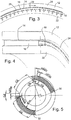
- Fig. 2 shows the outer race 12 in traction contact with the OD of traction ring 14 when the actuator ring 16 is energized in one or more (and preferable three or more) equally spaced zones.
- the traction ring 14 is mechanically fixed and/or bonded to the actuator ring 16.
- the actuator ring is mechanically fixed and/or bonded to the inner race 22.
- Electrodes 18 are in electrical contact with the actuator ring 16 providing a charge across the actuator ring to the other side. Between each of the contacts 20 between the traction ring and the outer race there are non-contacting gaps 24.
- the traction ring has an outside diameter of 3.98" when it is not elastically deformed.
- the outer race in this example, has an internal diameter of 4" leaving a gap between the two diameters of .01" inches (if the electro-reactive actuating ring is not energized and/or in a neutral position) but significantly larger gaps or significantly smaller gaps may also be used. (Significantly larger and significantly smaller diameters for an actuator of this type are also possible ranging from diameters of 10 feet or more down to 1 inch or smaller or microscopically small using MEMS manufacturing techniques).
- FIG. 3 shows an example of the contact surfaces traveling counterclockwise along the outer race which will in turn produce a clockwise rotation of the outer race if the inner reference race is fixed.
- voltage is applied to electrodes 18 labeled with a "I”.
- Voltage is not applied to the electrodes 18 labeled "0”.
- Voltage is moving from low or zero to increased voltage at electrodes labeled " ⁇ ).
- Electrodes labeled ">” indicate voltage reducing from energized to lower or zero voltage. The voltage corresponds to the energized state of the energy source. Energizing progressively (sequentially) more electrodes and sections of the electro-reactive ring at the leading edge 26 of the contact areas (in Fig. 3 at the left side of each contact) the outer ring is caused to rotate clockwise (Arrow A).
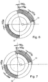
- Fig. 4 shows a cross section of a simplified example of a motion producing device.
- this cross section illustrates components necessary for the basic operating principle, including outer race or member 12, inner ring or reference member 22, traction ring 14, actuator ring or member 16 and electrodes 18, which define the actuator zones
- additional preferable features may include axial locating means for the outer race.
- Radial and/or axial roller or sliding bearings may be used, but with the significant radial load provided by the working principle of the actuator, it is believed that additional bearings may not be necessary for many applications.
- Fig. 5 shows an exaggerated partial schematic of an example of a motion producing device showing four points of contact between the deformed traction ring 30 and the output race. Also shown is a 90° section of the same traction ring in its relaxed state 32 with no forces acting on it from energizing of the actuation ring.
- Fig. 5 when the actuation ring is energized at four equally spaced positions such that the traction race comes into contact with the ID of the output race, sections between the contact areas exhibit an outer surface which is compressed (as compared to when the traction ring is in the relaxed state) as shown in Fig. 5 by the change in arc length from .07568" to the compressed length of .07103".
- the smaller radius section of the traction ring contact surface at the contact point with the output race requires the deformation of the traction ring into a smaller radius (than when it is in a relaxed state) whereby the outer surface of the traction ring must elongate as shown here by the increased length of each contacting section to an arc length of .09676".
- each of the 51 sections which is deformed into a tighter radius has the same root arc length of .06" and an outer surface arc length of .09676".
- a 90 degree segment of the outer rotor contact surface is also divided into 51 segments.
- the .07849" arc length of these segments (although longer than the arc length of the traction ring contact surface segments when the traction ring is in a relaxed state) are shorter than the .09676" arc length of the traction ring contact surface segments.
- the traction ring contact surface will have a greater surface length, for a given root arc length (in this illustration, the root length being .06") as it contacts the output race than it does when it is in the relaxed state.
- the curved arrow in Fig. 3 shows an example of the direction of contact surface progression (which has the appearance of a rotation) as results from the energizing of adjacent areas of the actuator ring in the clockwise direction, and the counterclockwise relative direction of movement of the contact surface of the traction ring contact surface which results, and the clockwise relative movement of the output ring which results.
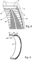
- Fig. 8 Shown in Fig. 8 is a simplified view of an array of electrical circuits as an example of one of many ways which can be used to supply electrical voltage and/or signal to and from the electro-reactive actuator ring 16. For simplicity, in this example, circuits to only one section of the actuator ring are shown here.
- All of these connections 40 or 42 preferably go to 10 input wires 44 to the device (the number 10 here being used as an example only, as fewer input and/or output wires or a greater number of input and/or output wires could also be used) and 10 output wires 46 from the device such that, in this example, each of the single input wires is connected to 10 equally spaced electrodes 18 on one side of the actuator ring, and each of the 10 output wires is connected to electrodes 18 opposite these input electrodes.
- 10 sets of input and output wires as shown in Fig. 8 , every 10 th positive electrode is preferably connected through a common circuit 42 to the same input wire to the device and every 10 th negative electrode is preferably connected through a common circuit 40 to the same output wire to the device.
- a computerized controller determines which electrodes are energized.
- the control system for this device is considered to be relatively straightforward because electrodes are simply energized and de-energized (preferably, but not necessarily, according to a predetermined voltage ramp up and ramp down function which may be dependent on speed and other variables) in sequence.
- the control algorithm does not make it necessary to provide feedback to the controller.
- the speed and/or frequency of the energizing and de-energizing of the electrodes will increase or decrease the speed of the output.
- the maximum torque output of the device will increase if increased voltage is supplied to the electrodes.
- the magnitude of this voltage can be controlled independently of the switching frequency.
- the voltage to the contacts By controlling the voltage to the contacts such that very light contact or minimal or no contact (for one or more of the contact areas) it is possible to allow free motion of the actuator joint such as when "back driving" of the robotic joint is desirable.
- One example would be for an anthropomorphic robot to produce smooth, humanlike movements.
- a high torque impulse can be applied to and through the actuator member which thus acts as a torque transmission path, and then once it has accelerated to the maximum desired speed, the voltage to the actuator can be reduced to where the components simply slides on the traction ring such that it decelerates at a rate which is dependent on the friction of the traction ring/output ring interface and the amount of preload as determined by input voltage to the contacts.
- Actuator materials may be electroactive polymers or non-electroactive transducers.
- electroactive polymers include dielectric elastomers (e.g. acrylic or silicone), electrostrictive polymer (e.g. (P(VDF-TrFE-CFE) 2 or graft elastomer), electrochemo-mechanical conducting polymer (e.g. polyaniline), mechano-chemical polymer/gels (e.g. polyelectrolyte) or piezoelectric polymer (e.g. PVDF);
- non-electroactive transducers include electrostatic devices (e.g. integrated force array), electromagnetic (e.g. voice coil), piezoelectric (e.g.
- PZT ceramic
- PZN-PT single crystal
- shape memory alloy e.g.. TiNi
- shape memory polymer thermal (expansion)
- magnetostrictive e.g. Terfenol-D, Etrema products
- natural muscle e.g. human skeletal
- Electro-reactive materials can be very fast acting, and some of them can also generate very high force as they expand. The drawback of these materials is that many of them are not able to transmit force over a high displacement. Piezo ceramics, for example, are generally limited to an expansion ratio of approximately 1% or 2%. This actuator takes advantage of the high speed and high force of Piezo and/or polymer and/or other electro-reactive materials which expand and/or contract when a voltage is applied to them.
- Fig. 9 shows a cross-section schematic of a simplified example of a actuator of a motion producing device with two sets of actuator rings or members 56 and traction rings or members 14 configured in such a way as to provide axial stability for the output ring or member 52. Shoulders on the reference member may be used to help axially align the actuator member 56.
- the actuator member 56 and its segments 56A and 56B are also constrained axially by centrally located shoulders on either side of a central protrusion, and lateral shoulders on respective lateral protrusions.
- the actuator member includes a first actuator segment 56A and a second actuator segment 56B that are spaced apart axially.
- the traction rings 54 are mechanically fixed and/or bonded to the actuator rings 56.
- the actuator rings 56 are mechanically fixed and/or bonded to the inner race 62. Electrical contacts are not shown in Fig. 9 .
- Attachments to the inner and outer rings are not shown in some of the figures in this disclosure. There are many ways to connect the reference members and output members to external components including bolting, adhering, welding, and fabricating as one piece with other components.
- Fig. 10 shows a section view of a simplified schematic of an example of a rotary actuator according to present device where the actuator race 16 and traction ring 14 are mechanically fixed to and/or bonded to the outer ring 12.
- the inner ring in this example serves as the output race.
- Fig. 11 shows a simplified cross-section schematic view of an example of a motion producing device
- the inner ring 22 is the output
- the actuator ring 16 inside diameter surface 64 serves as the contact surface with the inner ring.
- Fig. 12 shows a simplified cross-section schematic view of an example of device motion producing device, the outer ring 12 is the output, and the actuator ring 16 outside diameter surface 66 serves as the contact surface with the outer ring.
- Fig. 13 shows a simplified cross-section schematic view of an example of a motion producing device with outer ring 62 and inner ring 72 where the actuator rings 76 are constructed with a taper to provide stability between the reference output race.
- the first actuator segment and the second actuator segment have axially tapered traction surfaces, and in this example, the respective first actuator segment 76A and the second actuator segment 76B taper oppositely.
- the number of contacts can be changed when the actuators at rest, or even when it is in operation for different effects.
- a greater number of waves is believed to be better with respect to reducing the shear displacement of the actuator ring between contacts but still maximizing torque.
- piezo ceramics or other alters sonic transducer suitable materials it may be possible to analyze the signal produced during actuation of these different areas of the actuator ring, to determine the rotational position and/or speed of the actuator output. If one or more anomalies in the outer race material (preferably somewhere radially outward from the contact surface) are designed into the system, it may be possible to sense the relative position of these anomalies to the inner ring using ultrasonic feedback transferred through the contact surfaces to the outer race. These ultrasonic signals will reflect off of the anomaly/s and may be readable by the same or it different section of the actuator ring which produced the signal.
- the actuator ring can be coated with a material that has the desired traction contact characteristics, or electro-reactive materials which provide the desired contact properties (such as high coefficient of friction when loaded, and for some applications, a minimal-wearing and non-stick-slip interface when loads are reduced and/or when sliding is desirable, such as during an over torque scenario or when it is desirable for the actuated member to move freely) can be used without a traction ring or without a different material coating on the traction surface.
- Fig. 14 shows an example motion producing device that uses a toothed interface 80 between the traction ring 86 (which in this case does not rely on traction and is preferably a low friction surface) and the output member.
- the output member is the outer ring 82 and the shape changing layer is attached to the inner reference ring 92.
- Conventional gear teeth can be used but it is preferable to use rounded gear teeth more similar to what is used in a conventional roller harmonic drive.
- four expanding areas are used at 90 degrees to each other. A higher or lower number of expanding (contacting) areas (or zones) can be used, as long at the inner toothed member has at least a one tooth difference from the outer toothed member in between each contact zone.
- Fig. 15 shows a similar toothed interface example that uses a toothed interface 110 between the traction ring 106 and the output member, with the shape changing layer 104 on the outer ring 102.
- the output member is the inner ring 112.
- Fig. 16 shows a simplified schematic section of a spherical example of a motion producing device, with an inner sphere 120, outer sphere 122 and actuation layer 124.
- Fig. 17 shows the detail of the window in Fig. 16 showing the schematic spherical example partially disassembled with an array of circles representing actuating inputs 126. These could be of any type depending on how the actuation material is caused to change shape.
- contacts with the output sphere can be created by deforming the actuation layer material so it expands to close in on the output sphere.
- the actuation layer could be preloaded against the output member and the actuation layer could be contracted everywhere except at the desired contact points) expanding and contracting of the material at the same time in different areas is a preferred method of actuating any of the devices in this disclosure if the material allows this combined actuation method.
- the contact surface of the output member is in continuous contact with the traction surface of the actuator member and may retract upon actuation.
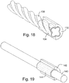
- Fig. 18 shows a simplified schematic helical/linear drive example with a sectioned housing/reference member 132 (such as could be used in place of a conventional ballscrew actuator) according to an example of a motion producing device (shown here in a relaxed state with a gap between the actuation layer contact surface and the helical shaft contacts surface).
- the contact surface of the output member and the traction surface each have cooperating helical shapes to convert rotation of the output member into linear motion.
- the shape change actuator member 134 By deforming the shape change actuator member 134 generating one or more (and preferably three or more) contact patches around the circumference of the helical shaft 132, and then causing these contact patches to move tangentially along the surface of the shaft, will cause the shaft to spin and, as a result of the helical shape, to move in an axial direction.
- the contact patches can be in a line parallel to the axes of the helix, and/or they can be helical in shape, and or another shape.
- the movement of the contact patches can be circular on a plane perpendicular to the axis of the helical shaft and/or in a helical motion and or another motion that has a circular and/or linear (parallel to the axis of the helical shaft) component to it.
- Fig. 19 shows a simplified schematic cylindrical drive example with a sectioned housing/reference member 142.
- the cylindrical shaft 140 can be caused to move in a linear direction and or in a rotating motion.
- linear motion can be generated while ensuring that no rotary motion occurs.
- a part of a cylinder with infinite radius forms a plane, and linear members within the plane then can be caused to translate with respect to each other according to the principle disclosed here.
- the patches or energized zones may be formed as a grid, as shown.
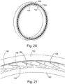
- Fig. 20 shows a simplified exemplary embodiment of a motion producing device with an outer ring or output member 152, an inner ring or reference member 162 and an actuator ring or member reinforcement construction which is designed for radial compliance and increased tangential rigidity.
- the reinforcement member 156 is preferably made of a material with a higher tensile and/or compressive strength and/or tensile and/or compressive rigidity than the shape change material in the chambers or flexures 154 between the reinforcement members.
- reinforcement member chambers 154 can have one or more electrodes 158 and/or other energizing features/connections. Energizing all or part of the shape change material in the reinforcement member chambers will close the gap 160 between the reference member contact surface and the output member contact surface.
- Radially expandable reinforcement member 156 shown in Fig. 21 in the relaxed position, is mechanically connected and/or bonded to the reference member 162, and also preferably serves as the contact surface with the output member 152.
- a non-limiting example of materials which could be used in this configuration including an output member of aluminum, of reference number of aluminum, a radially expandable reinforcement member made of nylon, and a shape change material in the reinforcement member chambers made of silicone electroactive material.
- the electroactive material in this example, is energized in a zone with a non-energized his own on either side (this can be accomplished by energizing one or more sets of electrodes) it will expand in the radial direction and cause the radius of the reinforcement member contact surface to decrease as it moves radially to contact the contact surface of the output member.
- This embodiment can also be configured with the radially expandable reinforcement member and expandable (and possibly contactable) shape change actuation material on the outer member with the output member as the inner race.
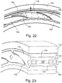
- Spiral arc coupling Any wave, whether in a liquid or in a solid, will cause the surface to travel in a somewhat circular or elliptical path. This circular path is one of the motion transfer principles of the Reactuator, and it is preferable to allow it to happen, at least to a certain extent..
- the expandable material reinforcement structure must allow torque to transfer from the contact surface of the OD of the actuation member to the inner reference member.
- This coupling causes a somewhat circular or elliptical path of a point on the contact surface as the wave propagates, and a near radial movement of a point on the contact surface radially outward from, and near the center of, an energized (or group of energized) actuation member zones when a wave is formed (as opposed to when a wave propagates).
- Non-radial flexures 164 as shown in Fig. 22 allow the outer surface of the actuation member 156 to move outward. They also allow the transfer of torque from the traction contact surface interface to the inner reference member 162. A non-radial straight flexure will cause a rotation of the outer surface of the actuation member generally around the inner attachment point of the flexures. This is non-ideal because it does not allow a natural movement of the outer surface radially outward when one cell is energized or in a somewhat circular or somewhat elliptical motion when the wave propagates.
- the pressure generated in all directions (generally radially outward from the center of each chamber) by the ER material when it is energized or by external pressurization of chamber material, will act on all the interior surfaces of the pocket/cell/chamber that contains it.
- one chamber is energized and the dotted lines show the resulting deflection of the reinforcement flexures.
- the pressure in the chamber has an increasing mechanical advantage on the left (convex relative to the pressurized material) flexure 164 as it straightens, and a decreasing mechanical advantage on the right (concave relative to the pressurized material) flexure 166 as it flexes.
- One of the most significant features of at least some embodiments is the direct and nonrotating connection between the contact surface of the reference member with the reference member. Essentially, this achieves an actuator (which can also be used as a motor) (which may, in certain configurations, even be usable as a generator) with minimal moving parts. The rest of the movement that is required to achieve rotation or other types of movement of the output member is accomplished by changing the shape of the reference member contact surface.
- the motion producing devices in one embodiment disclosed here takes advantage of high speed action shape change materials and combines these materials with a method of achieving high surface contact area and pressure to produce rotary and/or other types of motion from a simple, and cost effective device.
- high surface contact material or surface preparation such as very fine hairs (such as microfibers or microfilaments used by geckos for traction) can be used on one or both contact surfaces to increase traction and reduce the required compression force and contact area.
- This actuator is considered ideal for many extremely large applications as well as for many small applications including MEMs.
- actuation methods for the actuation shape change material including but are not limited to, a matrix of electrical wires which are able to exceed a critical threshold voltage of the material they are connected to where two or more energized wires cross.
- the preferable material or coating has a limited reaction below this voltage, so the reaction zone can be manipulated in any direction on a flat plane or on the surface of a sphere, for example, or to produce rotary and or axial motion of a rod in a cylinder.
- a contact surface which can be made to pull away from and/or to come into contact with the output surface by energizing and/or de-energizing portions of the actuation member to generate one or more contact points against the output member which can be moved in one or more directions along the contact surface if the output member.
- the reactive material or structure can also be configured to pull away from being in contact with the contact surface of the output member when energized.
- Some embodiments of a motion producing device can use any type of material or structure presently known our existing or known or existing in the future which reacts to an input signal such as a change in voltage, and/or a chemical input, and/or a light signal input, and/or a heat signal input, and/or gas pressure, and/or hydraulic pressure, and/or mechanical means such as rollers and or spheres and or gears which cause one or more contact patches to move along a contact surface if an output member.
- an input signal such as a change in voltage, and/or a chemical input, and/or a light signal input, and/or a heat signal input, and/or gas pressure, and/or hydraulic pressure, and/or mechanical means such as rollers and or spheres and or gears which cause one or more contact patches to move along a contact surface if an output member.
- Micro machines using this principle can be manufactured using mems techniques for micro, miniature, or even nano machines. Electricity supplied by one or more wired or wireless methods with wirelessly controlled switches at positions on an actuator member may be used to control the position and energizing of movable zones on the actuator member.
- shape change material examples include but are not limited to the following: nano fiber piezo materials, expanding and/or contracting gels, peizoelectric materials, magnetostrictive materials (magnetic field causes contraction/expansion), photostrictive (light exposure causes contraction/expansion), shape memory alloys, shape memory polymers, electrochemo-mechanical polymers, electroactive polymer, electrostricter polymer, mechano-chemical polymer/gel, expanding and or contracting meta-materials, electrostatic actuation materials, structures which exaggerate or amplify the effect of any of the able materials or other materials not yet known, materials or structures which are energized by gas and/or incompressible fluid pressure.
- the output race may, in some cases travel in the same direction as the movement of the contact patch/s.
- the traction or toothed surface that interacts with the driven surface of the output member is fixed to the reference member and allows deformation of the shape change (actuation) layer by virtue of elastic deformation of the shape change member material (and the traction/toothed ring material).
- the present device can use an exaggerating structure, such as an array of lever arms powered by piezo's, or a tangentially rigid array with reactive material filling the voids to increase the radial motion generated by a shape change material.
- an exaggerating structure such as an array of lever arms powered by piezo's, or a tangentially rigid array with reactive material filling the voids to increase the radial motion generated by a shape change material.
- a segmented or partially segmented actuation member will allow radial expansion with less deformation of adjacent areas.
- Torque or force transfer from reference to output race can be radial or axial or at an angle as long as the expansible ER material is located along the line of force transfer, it is possible to maximize the contact force resulting from its expansion, and therefore, the traction force.
- the ratio of the diameter of the output member to the diameter of the reference member is preferably less than 2:1 and more preferably less than 1.5:1 and even more preferably less than 1.1:1.
- the traction surface and contact surface may have 100% contact at all times (under contact and/or slight preload compression) and two or more traveling higher compression zones. Advantages of this include it being self locking when the power fails. If a material which can contract radially with a negative (or the opposite) charge is used, then the Reactuator can also be free spinning if desired by contracting all of the circumference at the same time.
- a slightly preloaded (stretched) deformable surface member is preferred where this surface is stretched outward (if attached to inner race) when at rest to achieve 100% contact when not powered, and then compressed radially outward in two or more traveling areas to cause motion...and then contracted (allowed to contract) by contracting the ER material around complete circumference.
- Some embodiments may use any means of compressing or deforming the surface as a result of any type of actuation which makes the surface, or a subsurface member not round in one or more places so as to elongate the contact surface between the ID and OD.
- This method of elongation can be magnetic components that pull together and deform a material such that it pushes outward on the OD of the inner member or a subsurface of the OD of the inner member. The same could be accomplished by deforming the ID of the outer member.
- the motion producing principle may also be used for a linear actuator. Either inside a tube or at least two opposing surfaces. There needs to be two rigid or semi-rigid opposing members that prevent full expansion of the contact surface or sub surface such that a high (or adjustable) contact force is achievable.
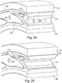
- Fig. 23 shows a preferred embodiment of a hydraulically or pneumatically actuated version of the Reactuator.
- the expandable material need only be a material that can be expanded, streteched or moved outward away from or towards a surface, so for example the confining walls of a chamber and the material of the actuator member around the chamber, and need not be an inherently expandable material such as an electroactive material.
- Various fluids, whether incompressible or compressible, may be used for or in place of the hydraulic fluid.
- the hydraulic or pneumatic version can work by expanding by pressurizing or contracting by depressurizing to press or retract the traction surface of the actuator member as the case may be to or from the contact surface of the output member.
- the center member 170 is preferably a low durometer flexible material such as but not limited to 40 durometer silicone or urethane with a high Poisson's ratio such as but not limited to .48 or higher, urethane which does not compress significantly when it deforms under pressure or force.
- the side plates 174 are shown as separate segments but can also be connected and are a rigid material such as metal or plastic.
- the seal member 178 is a high durometer flexible but preferably not compressible material such, but not limited to 90A silicone or urethane. When hydraulic flow and pressure are increased in a cell, the cavity 180 in the urethane center member 170 expands outward and the outer surface of the center member 170 insert expands against the inner surface of the seal member 178.
- the seal member 178 is high enough durometer that it is sealed from extruding past the side plates 174 where they seal against the actuation member 176.
- the actuation member 176 is between an outer ring 172 and an inner ring 182.
- the seal member 178 has less deformation for a given actuator member cell expansion than the center member 170 so a higher durometer urethane is not highly stressed here.
- this configuration will exert the same pressure on the actuator member 176 (and will result in the same traction between the actuator member and the output member contact surface) as if the cell was filled with hydraulic fluid, except the urethane is easy to "seal" and it also acts as a zero leak seal for the hydraulic fluid.
- Advantages of this system include the potential for extremely high torque with a consistent torque thru the entire range of motion as compared to a typical hydraulic actuator system (such as on an excavator that has a constantly changing lever arm). There are also no sliding seals exposed to hydraulic pressure or fluid.
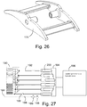
- Figs. 24-26 show the hydraulic drive configuration sequentially disassembled, first with the side plates removed, as shown in Fig. 24 , then with the center member removed, shown in Fig. 25 .
- Fig. 26 shows the side plate assembly 174, with the attachment of the two halves together not shown.
- Motor 196 for example a variable speed electric or hydraulic motor, drives a swashplate pump 194.
- Each piston 200 of a swashplate pump 194 supplies an array of equally spaced Reactuator cells 190 through hydraulic supply lines 192.
- the swashplate pump 194 preferably uses variable displacement of the pistons.
- Each cell 190 (or set of equally arrayed cells so one inlet and outlet valve could drive two or more equally arrayed cells around the actuator) could be controlled by inlet and discharge valves but a more efficient drive would use a hydraulic motor with a single piston supplying flow and pressure to each set of equally arrayed cells.
- a cooling circuit 184 including heat exchanger 186 may be in fluid connection with the cells 190 and hydraulic supply lines 192. A separate cooling circuit is required for each piston driven circuit. The fluid may be circulated through the heat exchanger 186 by check valves 188, or by circulation pump 198. The cooling circuit is unnecessary if the actuator structure provides sufficient heat exchange.
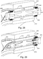
- Fig. 28 is a simplified schematic cross-section of electromechanical actuation of the Reactuator.
- an electro magnet 216 is used to displace a center member 210, a small volume of low durometer non-compressible flexible material such as, but not limited to, 40 durometer urethane.
- the pressure developed can be extremely high.
- very small gap 218 between the actuation ring 206 and the ID face of the output ring 202 (or a very thin compressible and/or deformable member in the 100% contact embodiment) very small volume displacements of the urethane can produce very high traction forces as the result of small actuation member deflection.
- Actuation ring 206 may be mechanically connected to the reference ring 212.
- the magnet is preferably configured so the magnetic force will be the highest when the cell pressure also needs to be the highest. This is a particular advantage of this system with regard to power density as compared to an electric motor which has an output torque which is an average of the weakest and strongest positions of the electromagnetic coils and magnets or inductance members.
- the higher durometer seal member 208 material (such as, but not limited to, 90 durometer urethane) acts like a backup ring, similar to the hydraulic actuation embodiment to prevent extrusion of the lower durometer urethane material past the sidewall seals 204 and the piston ring seal member 208.
- Another advantage of this actuation method over the hydraulic system is the elimination of hydraulic fluid, the elimination of a hydraulic pump and hydraulic lines. Very high frequency movement of the magnets should be possible. It may even be possible to recapture some of the rebound energy on the backstroke of the piston by inducing a current or using a permanent magnet in the piston driver 214.
- Fig. 29 shows a simplified schematic cross-section of the electromechanical actuation of the Reactuator partially disassembled showing the low durometer urethane center member 210 and how the piston displacement will get transferred to the larger volume of urethane (which could be several pieces of different durometers or all one piece but this is a preferred example of how it could be configured).
- the purpose of the gradually flaring tube in the sidewall member 204 is to transmit the motion of the small diameter piston to the larger volume of the low durometer urethane without exceeding elastic limit of the urethane at any one point.
- an energy source for activating an electroactive material such as a polymer or elastic material is shown in an electrical schematic.
- On the left side elements 220 are Reactuator cells with electrodes (as shown in the example of Fig. 1 ) or coils (as shown in Fig. 29 ) coupled by wire pairs 222 to relays or power control circuits 224.
- Each relay 224 and wire pair 222 energizes an array of equally spaced electrodes or coils.
- a simple timing unit 226 formed of a programmed CPU or hardwired circuit controls timing power from power supply 228 to each relay 224 to energize the arrays sequentially.
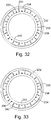
- Figs. 31-34 show a simplified schematic of a rotary actuator with a rigid inner reference ring 242, a rigid outer output member 232, and an electro-reactive actuation ring 234 with two or more arrays of electrodes 238 at different radial distances from center. Dark electrodes indicate energized electrodes. In the example shown in Figs. 31-34 the output member rotates in the same direction as wave propagation.
- Fig. 31 shows Phase 1, where two or more preferably equally arrayed zones are energized as indicated by the dark electrodes (three zones are shown in Fig. 31 as an example but fewer or more zones may be used).
- Different types of electro-reactive materials may contract or expand along the direction of which the voltage is applied. For this example the voltage is applied from electrodes on one axial side of the electro-reactive ring 234, to identical electrodes on the opposite axial side (not shown).
- one or more of the outer array of electrodes in each zone are energized 240 to contract the continuous actuation ring axially so that it expands radially outward to create contact with the outer race 232.
- Fig. 32 shows Phase 2, where energizing one or more of the inner array electrodes 230 to the left of the outer energized electrodes 240 contracts the actuator ring material 234 to the left by increasing tension from the outer energized electrodes 240 inwardly and in the direction of wave motion.
- the contact patch between the actuator ring 234 and the outer ring 232 then progresses counterclockwise, in this example, transmitting relative motion from the reference race 242 to the outer race 232.
- Fig. 33 shows Phase 3, where electrodes 238 are progressively energized at the leading edge of the wave and de-energized along the trailing edge of the wave in a pattern that generates radial expansion to achieve contact pressure against the outer race 232.
- circumferential tension can be developed by energizing additional electrodes on the inner array 230 aheadof the wave with a counter-clockwise progressing wave.
- Electrodes energizing are possible and have been conceived by the inventor. Materials which expand in the direction of voltage, or expand or contract depending on the polarity of the energization, can be energized and a variety of patterns which accomplish the following to principles of this device.
- Radial force between the actuation ring and the output race results from energizing two or more zones so that contact pressure is achieved or increased against the outer race in these zones.
- the internal stress of the actuation ring is increased and/or decreased circumferentially to cause a progression of the wave crests around the actuator.
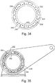
- Figs. 35-36 show a simplified schematic of a rotary actuator with a rigid inner reference ring 262, a rigid outer output member 252, and an electro-reactive actuation ring 254 with two or more arrays of electrodes 238 at different radial distances from center.
- the output member 252 rotates in the opposite direction of wave propagation.
- electro-reactive materials have an inherent elasticity. By energizing two or more zones so the material expands radially (or in whatever direction closes the gap between the reference member and the output member) the propagation of these waves by the sequential energizing of adjacent electrodes will cause relative movement of the output member in the opposite direction of wave propagation. Un-energized areas will deform elastically to allow the expansion of the material 254 in the energized zones. Radial arrows A show the expansion of the material that is energized. Circumferential arrows B show the elastic deformation of the un-energized material.
- Figs 36A and 36B show and example of the progression of a wave with exaggerated movement of output 252 clockwise as wave propagates counter-clockwise.
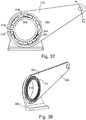
- Fig. 37 shows a simplified schematic of a rotary actuator with a rigid inner reference ring 282, a rigid outer output member 272 with a rigid rotational output, and an electro-reactive actuation ring 274 with two or more arrays of electrodes 278 at different radial distances from center. It is, in many applications, desirable to achieve a rigid rotational output with low rotational elasticity. In these applications high rigidity can be achieved by energizing the electro-reactive material as circumferential direction and in the direction of torque transfer. In this way, a relatively elastic electroactive material such as electro-reactive polymer, can simulate a rotationally rigid material by providing a circumferential tension on the material which is proportional to the torque applied to or through the output member.
- Positive and negative charges are shown in Fig. 37 as examples of how the polarity of the electrical charge can be used to cause contraction or expansion of electro-reactive material 274 in different directions.
- positively charged electrodes 284 on the visible side of the actuator ring together with negatively charged electrodes on the opposite (nonvisible) axial side of the actuation ring cause contraction of the electro-reactive ring 284 axially with the corresponding expansion of the material in the radial direction to increase the contact pressure against the output ring 280 in these zones.
- negatively charged electrodes 286 adjacent to the wave crests and in the opposite direction of the applied torque are energized to contract the electro-reactive material 274 circumferentially to increase the stiffness of the output contact in the direction of the torque load.
- Electrodes 278 can be fewer or greater in number and placed anywhere on the surface or embedded in the actuation member ring 274.
- the ring is preferably one continuous piece but could be separate sections, layers or rings.
- a continuous ring as shown allows the contraction forces to be direct between any one or more electrodes to any other one or more electrodes on the same or opposite sides axially parallel to the actuator axis or had angles along a plane perpendicular to the axis or actually through from one side toward the other side of the actuator ring but at an angle which is not parallel to the actuator axis.
- the same principle can be applied to a non-round actuator such as the linear actuator shown here.
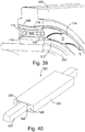
- Figs. 38 and 39 show a hydraulically or pneumatically actuated version of the Reactuator made in accordance with the embodiment shown in Fig. 23 except with an opposed tapered outer race 302.
- the outer surface of the seal member 308 is V-shaped following the opposed tapered surface of the outer race 302.
- Actuation member 176 conforms to the opposed tapered surface of the outer race 302 and the outer surface of the seal member 308.
- Fixed stand 300 is press fit into the reference member 312 and the output arm 304 is manufactured as one piece with the output ring.
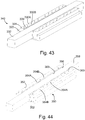
- a linear actuator 320 is shown in Figs. 40 , 41 and 42 .
- a housing 322 forms a channel and secures a first linear actuator member 324 and a second linear actuator member 326 for example by bonding to opposed sides of the housing 322.
- Respective traction members 328 are bonded to the linear actuator members 324, 326.
- the linear actuator members 324, 326 may be made of electroactive material energized by the electrodes 330 or made of other materials using other energizing methods disclosed in this patent document.
- a linear output member 332 may rest on the housing 322 and be confined by the actuator members 324, 326 and their traction surfaces 328. Lubrication or bearings may be provided for the linear output member 332 in the housing 322.
- the housing 322 may encase the actuator members 324, 326 as shown in Fig. 40 .
- a linear actuator 340 may have two rows of electrodes 330A and 330B.
- Fig. 44 shows an example of a linear actuator 350 in which the actuator members 352 for example by electrodes 354A (energized) and 354B (de-energized) is sequentially energized to contract the material of the actuator member 352 and pull the traction surface 356 away from the contact surfaces 360 of the output member 358.
Description
- Actuators.
- High torque actuators are difficult to create.
US Patent no. 6155220 claims to describe a compact cam phaser that has a flexible spline deformed into a non-round shape and engaging a mating ring gear or circular member at angularly spaced locations for transferring camshaft drive torque between them. While this patent seems to disclose a working embodiment, it uses separate components for torque transfer than for actuation and has other differences from what is disclosed here. -
JP H02 129436 - The inventor has provided in one embodiment a motion producing device with high torque transfer capabilities.
- In an embodiment, there is disclosed a motion producing device according to the subject-matter of
independent claim 1. - Examples will now be described with reference to the
figures 1-19 ,27 ,30-37 and40-44 and Embodiments will now be described with reference to thefigures 20-26 ,28 ,29 ,38 and39 , in which like reference characters denote like elements, by way of example, and in which: -
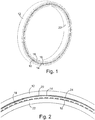
Fig. 1 is an example of a low-profile motion producing device. -
Fig. 2 is a simplified partial section of the motion producing device ofFig. 1 . -
Fig. 3 is a simplified partial section of the motion producing device ofFig. 1 showing an example of an applied voltage pattern. -
Fig. 4 is a simplified cross section of the motion producing device ofFig. 1 . -
Fig. 5 is an exaggerated partial schematic of an example of a motion producing device showing the motion transfer principle of operation. -
Fig. 6 is the schematic ofFig. 5 showing the arc length of the outer rotor contact surface. -
Fig. 7 is the schematic ofFig. 5 showing the arc length of the traction ring in a relaxed state. -
Fig. 8 is a simplified cross-section schematic of the motion producing device ofFig. 1 showing an array of electrical circuits. -
Fig. 9 is a simplified cross-section schematic of an example of a motion producing device with two sets of actuator rings and traction rings. -
Fig. 10 is a simplified cross-section schematic of an example of a motion producing device where the actuator race and traction ring are mechanically fixed to the outer ring. -
Fig. 11 is a simplified cross-section schematic of an example of a motion producing device where the inner ring is the output. -
Fig. 12 is a simplified cross-section schematic of an example of a motion producing device where the outer diameter of the actuator ring is the contact surface with the outer ring. -
Fig. 13 is a simplified cross-section schematic of an example of a motion producing device where the actuator rings are constructed with a taper. -
Fig. 14 is a simplified cross-section schematic of an example of a motion producing device with a toothed interface between the traction ring and the outer ring. -
Fig. 15 is a simplified cross-section schematic of an example of a motion producing device with a toothed interface between the traction ring and the inner ring. -
Fig. 16 is a simplified cross-section schematic of a spherical example of a motion producing device. -
Fig. 17 is a detail of the spherical example ofFig. 16 . -
Fig. 18 is a simplified cross-section schematic of a helical/linear drive example of a motion producing device. -
Fig. 19 is a simplified cross-section schematic of a cylindrical drive example of a motion producing device. -
Fig. 20 is a simplified schematic of an embodiment of a motion producing device with a reinforced actuator ring construction. -
Fig. 21 is a simplified partial section of the motion producing device embodiment ofFig. 20 . -
Fig. 22 is a simplified schematic of an embodiment of a motion producing device with a reinforced actuator ring with non-radial flexures. -
Fig. 23 is a simplified cross-section schematic of an embodiment of a hydraulically actuated motion producing device. -
Fig. 24 shows the embodiment ofFig. 23 with the side plates removed. -
Fig. 25 shows the embodiment ofFig. 24 with the center member removed. -
Fig. 26 shows the side plates of the embodiment ofFig 23 . -
Fig. 27 is a schematic of a hydraulic circuit of an example of a hydraulically actuated motion producing device. -
Fig. 28 is a simplified cross-section schematic of an electromechanical actuation embodiment of a motion producing device. -
Fig. 29 shows the embodiment ofFig. 28 with the side plates removed. -
Fig. 30 is a schematic of an electrical circuit of an example of an electromechanical actuation motion producing device. -
Fig. 31 is a schematic of a rotary example of a motion producing device with multiple arrays of electrodes in a first phase of the actuation sequence. -
Fig. 32 shows the example ofFig. 30 in a second phase of the actuation sequence. -
Fig. 33 shows the example ofFig. 30 in a third phase of the actuation sequence. -
Fig. 34 shows the example ofFig. 30 with additional energized electrodes ahead of the wave. -
Fig. 35 is a schematic of a rotary example of a motion producing device where the output member rotates in the opposite direction of wave propagation. -
Fig. 36A shows the example ofFig. 35 as the wave propagates counterclockwise.Fig. 36B shows the example ofFig. 36A as the wave propagates further counterclockwise. -
Fig. 37 is a schematic of a rotary example of a motion producing device showing the principle of operation. -
Fig. 38 is a simplified schematic of a hydraulically or pneumatically actuated embodiment of a motion producing device with an opposed tapered outer race. -
Fig. 39 shows a simplified cross-section schematic of the embodiment ofFig. 38 . -
Fig. 40 is an iso view of a simplified schematic of a linear example of an actuator. -
Fig. 41 shows the example ofFig. 40 with partially sectioned housing. -
Fig. 42 shows a cross-section of the example ofFig. 30 with partially sectioned housing. -
Fig. 43 shows an example of a linear actuator with two rows of electrodes. -
Fig. 44 shows an example of a linear actuator in which the actuator member is energized to contract the material of the actuator member and pull the traction surface away from the contact surface. - Immaterial modifications may be made to the embodiments described here without departing from what is covered by the claims.
- Embodiments of the present device, sometimes called a Reactuator, are able to use the deformation of any material which expands and/or contracts when energized by and electrical voltage or other type of electric or electronic signal, to press a ring of material against the inner diameter (ID) of a circular outer race. When this contact is created at one or more positions around the race, and if the contacting area is moved circumferentially by energizing areas of the expanding material at the leading edge of the contact, and de-energizing (or reverse energizing) the areas of the expanding material at the trailing end of the contacting areas, the contacting areas can be caused to move in a circular pattern in either direction around the outer race. The non-contacting area of the traction ring between each contact will have a shorter perimeter distance (measured along the outside surface of the traction ring) than the art distance between the centers of adjacent contact areas measured along the contact surface of the outer ring. As a result, as the contact area progresses along the outer race, the outer race will be caused to rotate.
- All embodiments include an output member with a contact surface, a reference member and an actuator member attached to the reference member. The actuator member has a traction surface and comprises actuator zones. Each actuator zone is energizable, by various means such as those disclosed, to move a corresponding portion of the traction surface to change a contact state of the traction surface with the contact surface depending on an energized state of the actuator zone. The contact state can be in contact (extended or at rest position) or out of contact (at rest or contracted position). Energization can cause a material to expand or contract, and thus change the contact state. An energy source is operatively coupled to the actuator zones for sequentially changing the energized state of the actuator zones. As the actuator zones are sequentially energized, a wave moves the actuator member due to the circular path or elliptical
path of particles in the material caused by the wave, like water molecules in a wave moving through water. The wave causes the traction surface to move the output member. The movement of the actuator member causes a near radial movement (or perpendicular to the surface for linear actuator - or circular) of a point on the contact surface when the material or chamber below that point is energized during the formation (as opposed to propagation) of a wave crest. - In some embodiments, the actuator member provides a torque transmission path between the reference member and the output member. However, in some embodiments, other material can be in the torque transmission path.
- In an embodiment the output member has an axis and is circular. A reference member may be concentric with the axis, or otherwise has a shape that conforms to the shape of the output member. The actuator member may be attached around or along or to the reference member, either inside or outside, above or below. The actuator member may be made at least partially of an expandable or contractable material that is expandable or contractable when energized to press the traction surface against the contact surface. The energy source may be operatively coupled to the actuator member for sequential energization and actuation of circumferentially spaced portions of the actuator member. The reference member may be inside or outside the output member but the traction surface will always be between the reference member and the output member. Depending on the embodiment, the expandable or contractable material may be expandable or contractable when energized to press the traction surface against the contact surface from a position in which the traction surface is separated from the contact surface to a position in which the traction surface is in contact with the contact surface or the contact surface may be in continuous contact with the traction surface. For materials that contract when energized, the actuator member may be initially in contact and lose contact with the output member when energized. This would enable an actuator to be always in contact when not energized and then to operate to create rotational output by energizing areas which pull away form or have reduced contact pressure in a propagating wave.
- Depending on the embodiment, the actuation member may have sealed chambers which expand by movement of a material, for example by hydraulic actuation or compressible fluid actuation of expandable chambers within the expandable material or electromechanical actuation of expandable chambers within the actuation member. The chambers may be sealed with an inner lining of material that does not generate a lot of heat when energized such as silicone.
- One example, shown here in
Fig. 1 , has a traction surface formed by atraction ring 14 that is made of material such as nylon 66 (but many different types of plastic and-or metallic and-or ceramic and-or polyamide and/or other types of materials may be used). Traction coatings on the outside of the actuator surface (which is in contact with the outer race) may also be used instead of a separate ring (not shown). As shown inFig. 1 , the actuator member provides a torque transmission path between the inner reference ring and the output ring. If the actuator ring material has the desired characteristics such as a coefficient of friction which provides the desired torque, then coatings and/or a separate traction ring may not be necessary. Other desirable characteristics of this traction ring include the ability to deform slightly in shear in the direction of rotation enough to prevent undue sliding between the traction ring and the outer race. When sliding does occur, it is preferable that this material, or coating, or combination of materials does not create significant each or wear. - The actuator disclosed here takes advantage of the high forces that can be exerted by electro-reactive materials as well as the high-speed in which these materials can react to produce a high torque output together with a wide range of output speeds. It can also be constructed as a very low profile and light weight device. Certain configurations of the present device are also believed to be very cost effective by allowing the use of a low volume of material, and also, in some configurations, relatively inexpensive materials.
- The actuator disclosed here can also be used as its own bearing support, reducing the cost and weight and complexity of the additional bearings. The amount of torque transferred can also be varied separately from the variation of output speed, by increasing or decreasing the voltage (or other energizing signal) independently from the speed of the contact waveform progression circumferentially along the outer race.
-
Fig. 1 shows an example of a low-profile actuator. It uses a aluminum outer output race or member 12 (but many other materials could also be used), an aluminum inside reference race or member 22 (but many other materials may also be used), and electro reactive actuator ring ormember 16 preferably of a polymer (but other electro-reactive materials can also be used in other examples) which is fixed to theinner race 22, and atraction ring 14 made of nylon 66 (but many other materials can
also be used) and fixed to the outside of theactuator ring 16 and contacts the ID of theouter race 12 anywhere the actuator ring is energized. Due to the high expansion force generated by some electro-reactive materials, and because of the relatively high flexibility of a material likenylon 66, a large number of contacts can be provided between theouter race 12 andtraction ring 14.. The surface area of these contacts can also be extremely high (as compared to, for example, the contact of a roller on a race which is a very thin line) and so the combination of this high surface area and high contact pressure is believed to be able to produce a output torque which may exceed certain conventional actuator systems of similar size and weight or provide a lower cost option. -
Fig. 2 shows theouter race 12 in traction contact with the OD oftraction ring 14 when theactuator ring 16 is energized in one or more (and preferable three or more) equally spaced zones. Thetraction ring 14 is mechanically fixed and/or bonded to theactuator ring 16. The actuator ring is mechanically fixed and/or bonded to theinner race 22.Electrodes 18 are in electrical contact with theactuator ring 16 providing a charge across the actuator ring to the other side. Between each of thecontacts 20 between the traction ring and the outer race there arenon-contacting gaps 24. - In one example, the traction ring has an outside diameter of 3.98" when it is not elastically deformed. The outer race, in this example, has an internal diameter of 4" leaving a gap between the two diameters of .01" inches (if the electro-reactive actuating ring is not energized and/or in a neutral position) but significantly larger gaps or significantly smaller gaps may also be used. (Significantly larger and significantly smaller diameters for an actuator of this type are also possible ranging from diameters of 10 feet or more down to 1 inch or smaller or microscopically small using MEMS manufacturing techniques). When, in this exemplary example, 10 sets (one "set" referring to two electrodes, one on either side or and of an area which is charged by an electrical current between these electrodes) of preferably equally spaced electrodes (but smaller numbers or greater numbers can also be used) on either axial side of the electro-reactive actuating ring are supplied a voltage, the material expands in the radial direction creating an array of contact surfaces 20 between the outer diameter (OD) of the
traction ring 14 and the ID of theouter race 12. In this example, there are 100 electrodes on either side of the traction ring (but a greater number or lesser number of electrodes could also be used with different effects). With 100 electrodes on either side of the actuator ring,
it is possible to have 2 or more, 3 or more, 4 or more, 5 or more, 6 or more, 7 or more, 8 or more, 9 or more, 10 or more, 15 or more, 20 or more, 25 or more, 30 or more, 35 or more, 40 or more, 45 or more, or 50 contacts between the traction ring and the outer race with non-contacting gaps between each of these contacts. With 10 contacts, as shown in this example, using a larger number of electrodes than the number of contacts, allows the contacting surface between the traction ring in the outer race to progress gradually from contacting to non-contacting along the leading edge of each contact. It also allows the trailing edge of each contact to progress gradually from a state of contacting to non-contacting.Fig. 3 shows an example of the contact surfaces traveling counterclockwise along the outer race which will in turn produce a clockwise rotation of the outer race if the inner reference race is fixed. As shown inFig. 3 , voltage is applied toelectrodes 18 labeled with a "I". Voltage is not applied to theelectrodes 18 labeled "0". Voltage is moving from low or zero to increased voltage at electrodes labeled "<). Electrodes labeled ">" indicate voltage reducing from energized to lower or zero voltage. The voltage corresponds to the energized state of the energy source. Energizing progressively (sequentially) more electrodes and sections of the electro-reactive ring at theleading edge 26 of the contact areas (inFig. 3 at the left side of each contact) the outer ring is caused to rotate clockwise (Arrow A). -
Fig. 4 shows a cross section of a simplified example of a motion producing device. Although this cross section illustrates components necessary for the basic operating principle, including outer race ormember 12, inner ring orreference member 22,traction ring 14, actuator ring ormember 16 andelectrodes 18, which define the actuator zones, additional preferable features (not shown) may include axial locating means for the outer race. Radial and/or axial roller or sliding bearings may be used, but with the significant radial load provided by the working principle of the actuator, it is believed that additional bearings may not be necessary for many applications. -
Fig. 5 shows an exaggerated partial schematic of an example of a motion producing device showing four points of contact between thedeformed traction ring 30 and the output race. Also shown is a 90° section of the same traction ring in itsrelaxed state 32 with no forces acting on it from energizing of the actuation ring. - Referring now to a 90° section of the traction ring in both the relaxed state and the deformed state, the internal arc length of the relaxed state (3.06") and the deformed state (0.62" + 2.46" = 3.06") are equal. In both states the inner surface of each of the 90° traction ring sections are divided into 51 equal sections of .06" arc length.
- Dividing the outer surface of the traction ring, in its relaxed state, gives us 51 sections, each with an arc length of .07568". As shown in
Fig. 5 , when the actuation ring is energized at four equally spaced positions such that the traction race comes into contact with the ID of the output race, sections between the contact areas exhibit an outer surface which is compressed (as compared to when the traction ring is in the relaxed state) as shown inFig. 5 by the change in arc length from .07568" to the compressed length of .07103". More importantly, for the purpose of this explanation of the motion transfer principle, the smaller radius section of the traction ring contact surface at the contact point with the output race requires the deformation of the traction ring into a smaller radius (than when it is in a relaxed state) whereby the outer surface of the traction ring must elongate as shown here by the increased length of each contacting section to an arc length of .09676". - This is shown in
Fig. 6 , where each of the 51 sections which is deformed into a tighter radius, has the same root arc length of .06" and an outer surface arc length of .09676". A 90 degree segment of the outer rotor contact surface is also divided into 51 segments. The .07849" arc length of these segments, (although longer than the arc length of the traction ring contact surface segments when the traction ring is in a relaxed state) are shorter than the .09676" arc length of the traction ring contact surface segments. As a result, the progression of the smaller radius deformation of the traction ring contact surface will "roll" along the contact race in the opposite direction to the rotational direction of the actuation ring and traction ring deformation as defined by the progression of the energized "wave" generated by the activation of each electrode in one direction or the other. - As a result of this elongation of the traction ring contact surface (where it is in contact with the output race) the traction ring contact surface will have a greater surface length, for a given root arc length (in this illustration, the root length being .06") as it contacts the output race than it does when it is in the relaxed state. This effect is significant enough, that the surface speed of the contact surface of the traction ring when it is deformed into a smaller radius in order to contact the output race will have a greater surface length for the root arc length than it would if it was in the relaxed state and if (hypothetically, for illustrative purposes) it was deformed in all directions to the same diameter as the output race contact surface with a consistent contact surface curvature all the way around the OD. This is shown in
Fig. 7 where a segment of the relaxed state traction ring is extended out to the output race where the arc distance at the traction ring diameter is .07849". - The curved arrow in
Fig. 3 shows an example of the direction of contact surface progression (which has the appearance of a rotation) as results from the energizing of adjacent areas of the actuator ring in the clockwise direction, and the counterclockwise relative direction of movement of the contact surface of the traction ring contact surface which results, and the clockwise relative movement of the output ring which results. - All segmentation shown in
Figs. 5-7 is strictly to illustrate the surface length of the various components and is not part of the construction or function of an actual physical device of the present disclosure. The deformation of an actual device is likely to be much less pronounced than the illustration shown inFigs. 5-7 . These are shown with exaggerated geometry to illustrate the principle. - Shown in
Fig. 8 is a simplified view of an array of electrical circuits as an example of one of many ways which can be used to supply electrical voltage and/or signal to and from the electro-reactive actuator ring 16. For simplicity, in this example, circuits to only one section of the actuator ring are shown here. All of theseconnections input wires 44 to the device (thenumber 10 here being used as an example only, as fewer input and/or output wires or a greater number of input and/or output wires could also be used) and 10output wires 46 from the device such that, in this example, each of the single input wires is connected to 10 equally spacedelectrodes 18 on one side of the actuator ring, and each of the 10 output wires is connected toelectrodes 18 opposite these input electrodes. With 10 sets of input and output wires, as shown inFig. 8 , every 10th positive electrode is preferably connected through acommon circuit 42 to the same input wire to the device and every 10th negative electrode is preferably connected through acommon circuit 40 to the same output wire to the device. - A computerized controller determines which electrodes are energized. The control system for this device is considered to be relatively straightforward because electrodes are simply energized and de-energized (preferably, but not necessarily, according to a predetermined voltage ramp up and ramp down function which may be dependent on speed and other variables) in sequence. In its simplest form, the control algorithm does not make it necessary to provide feedback to the controller. The speed and/or frequency of the energizing and de-energizing of the electrodes will increase or decrease the speed of the output. The maximum torque output of the device will increase if increased voltage is supplied to the electrodes. The magnitude of this voltage can be controlled independently of the switching frequency.
- By controlling the voltage to the contacts such that very light contact or minimal or no contact (for one or more of the contact areas) it is possible to allow free motion of the actuator joint such as when "back driving" of the robotic joint is desirable. One example would be for an anthropomorphic robot to produce smooth, humanlike movements. A high torque impulse can be applied to and through the actuator member which thus acts as a torque transmission path, and then once it has accelerated to the maximum desired speed, the voltage to the actuator can be reduced to where the components simply slides on the traction ring such that it decelerates at a rate which is dependent on the friction of the traction ring/output ring interface and the amount of preload as determined by input voltage to the contacts.
- Actuator materials may be electroactive polymers or non-electroactive transducers. Examples of electroactive polymers include dielectric elastomers (e.g. acrylic or silicone), electrostrictive polymer (e.g. (P(VDF-TrFE-CFE)2 or graft elastomer), electrochemo-mechanical conducting polymer (e.g. polyaniline), mechano-chemical polymer/gels (e.g. polyelectrolyte) or piezoelectric polymer (e.g. PVDF); examples of non-electroactive transducers include electrostatic devices (e.g. integrated force array), electromagnetic (e.g. voice coil), piezoelectric (e.g. ceramic (PZT) or single crystal (PZN-PT)), shape memory alloy (e.g.. TiNi), shape memory polymer, thermal (expansion), magnetostrictive (e.g. Terfenol-D, Etrema products) and natural muscle (e.g. human skeletal) (from Kornbluh, R. et al., 2002, Electroactive polymers: An emerging technology for MEMS, MEMS/MOEMS Components and Their Applications, Proc. of SPIE Vol 5344, pp. 13-27).
- Electro-reactive materials can be very fast acting, and some of them can also generate very high force as they expand. The drawback of these materials is that many of them are not able to transmit force over a high displacement. Piezo ceramics, for example, are generally limited to an expansion ratio of approximately 1% or 2%. This actuator takes advantage of the high speed and high force of Piezo and/or polymer and/or other electro-reactive materials which expand and/or contract when a voltage is applied to them.
- Depending on the electrical properties of the electro-reactive material, it may be necessary to provide a level of insulation between the areas of the actuator ring which are energized by each set of electrodes. It would be possible to use individual separated pieces of electro-reactive material between each of the electrodes, but the rotational sheer load on the actuator ring may be substantial and the use of a one piece actuator ring is desirable for this reason. Other variations, such as connecting electrodes on both sides of the actuator ring which are not directly opposite each other can be used to produce various effects.
- There are very many ways to configure this basic operating principle into an actuator, motor, or another rotary device. Other examples would include the actuator ring attached to the outer ring (with the outer ring being the fixed or "reference"ring) with a rotating inner ring as the output.
-
Fig. 9 shows a cross-section schematic of a simplified example of a actuator of a motion producing device with two sets of actuator rings or members 56 and traction rings ormembers 14 configured in such a way as to provide axial stability for the output ring ormember 52. Shoulders on the reference member may be used to help axially align the actuator member 56. The actuator member 56 and itssegments first actuator segment 56A and asecond actuator segment 56B that are spaced apart axially. The traction rings 54 are mechanically fixed and/or bonded to the actuator rings 56. The actuator rings 56 are mechanically fixed and/or bonded to theinner race 62. Electrical contacts are not shown inFig. 9 . - Attachments to the inner and outer rings are not shown in some of the figures in this disclosure. There are many ways to connect the reference members and output members to external components including bolting, adhering, welding, and fabricating as one piece with other components.
-
Fig. 10 shows a section view of a simplified schematic of an example of a rotary actuator according to present device where theactuator race 16 andtraction ring 14 are mechanically fixed to and/or bonded to theouter ring 12. The inner ring, in this example serves as the output race. -
Fig. 11 shows a simplified cross-section schematic view of an example of a motion producing device, theinner ring 22 is the output, and theactuator ring 16 insidediameter surface 64 serves as the contact surface with the inner ring. -
Fig. 12 shows a simplified cross-section schematic view of an example of device motion producing device, theouter ring 12 is the output, and theactuator ring 16 outsidediameter surface 66 serves as the contact surface with the outer ring. -
Fig. 13 shows a simplified cross-section schematic view of an example of a motion producing device withouter ring 62 andinner ring 72 where the actuator rings 76 are constructed with a taper to provide stability between the reference output race. Thus, the first actuator segment and the second actuator segment have axially tapered traction surfaces, and in this example, the respectivefirst actuator segment 76A and thesecond actuator segment 76B taper oppositely. - In order to achieve effective operation of an example of a motion producing device it will be necessary to allow the actuator ring and/or the traction ring to elastically deform in shear as a result of the outer ring rotating relative to the inner ring while there is a direct connection between traction surface through the actuator ring to the inner ring. The higher this shear deformation of the traction ring and/or actuator ring, the lower the efficiency of the actuator because the energy which goes into elastically we deforming these components is not recovered and may cause sliding of the traction ring (or traction surface of no separate traction ring material is used) against the outer race at the leading and/or trailing edge of each contact.
- Longer (in the circumferential direction) contact surfaces will provide paths with higher torque transmission capacity but will produce greater shear and greater inefficiency. For this reason, it is preferable to energize fewer electrodes at each contact when the system is operating under low torque to provide the necessary torque with the shortest possible contact link at each contact. When higher torque is required, the width of each contact can be increased without changing the number of contacts.
- The number of contacts (waves peaks) can be changed when the actuators at rest, or even when it is in operation for different effects. A greater number of waves is believed to be better with respect to reducing the shear displacement of the actuator ring between contacts but still maximizing torque. The closer the contacts are together, the less differential length there will be between each contact with respect to the length of the circumferential distance along fixed race between contact centers and the perimeter length of the traction ring between contact centers. This will have the effect of reducing the rotational speed of the output ring for a given wave rotation speed.
- If piezo ceramics or other alters sonic transducer suitable materials are used, it may be possible to analyze the signal produced during actuation of these different areas of the actuator ring, to determine the rotational position and/or speed of the actuator output. If one or more anomalies in the outer race material (preferably somewhere radially outward from the contact surface) are designed into the system, it may be possible to sense the relative position of these anomalies to the inner ring using ultrasonic feedback transferred through the contact surfaces to the outer race. These ultrasonic signals will reflect off of the anomaly/s and may be readable by the same or it different section of the actuator ring which produced the signal.
- Additional ultrasonic and/or other types of sensors may be used in conjunction with the electro-reactive materials which are configured to transfer torque and motion as described here. The actuator ring can be coated with a material that has the desired traction contact characteristics, or electro-reactive materials which provide the desired contact properties (such as high coefficient of friction when loaded, and for some applications, a minimal-wearing and non-stick-slip interface when loads are reduced and/or when sliding is desirable, such as during an over torque scenario or when it is desirable for the actuated member to move freely) can be used without a traction ring or without a different material coating on the traction surface.
- Instead of pure traction, it may be beneficial in some applications to use a geared interface between the actuator and or traction ring and the outer race.
- Example of a toothed engagement.
Fig. 14 shows an example motion producing device that uses atoothed interface 80 between the traction ring 86 (which in this case does not rely on traction and is preferably a low friction surface) and the output member. In this example, the output member is theouter ring 82 and the shape changing layer is attached to theinner reference ring 92. Conventional gear teeth can be used but it is preferable to use rounded gear teeth more similar to what is used in a conventional roller harmonic drive. In this simplified section view, four expanding areas are used at 90 degrees to each other. A higher or lower number of expanding (contacting) areas (or zones) can be used, as long at the inner toothed member has at least a one tooth difference from the outer toothed member in between each contact zone. -
Fig. 15 shows a similar toothed interface example that uses atoothed interface 110 between thetraction ring 106 and the output member, with theshape changing layer 104 on theouter ring 102. In this example, the output member is theinner ring 112. - Example of a spherical/semi-spherical surface:
Fig. 16 shows a simplified schematic section of a spherical example of a motion producing device, with aninner sphere 120,outer sphere 122 andactuation layer 124. -
Fig. 17 shows the detail of the window inFig. 16 showing the schematic spherical example partially disassembled with an array of circles representingactuating inputs 126. These could be of any type depending on how the actuation material is caused to change shape. In aspherical actuator 124 as shown here, contacts with the output sphere can be created by deforming the actuation layer material so it expands to close in on the output sphere. Alternatively (and as would apply to other examples in this disclosure, the actuation layer could be preloaded against the output member and the actuation layer could be contracted everywhere except at the desired contact points) expanding and contracting of the material at the same time in different areas is a preferred method of actuating any of the devices in this disclosure if the material allows this combined actuation method. In this example with the actuator member pre-loaded, the contact surface of the output member is in continuous contact with the traction surface of the actuator member and may retract upon actuation. - Example of helical linear actuator:
Fig. 18 shows a simplified schematic helical/linear drive example with a sectioned housing/reference member 132 (such as could be used in place of a conventional ballscrew actuator) according to an example of a motion producing device (shown here in a relaxed state with a gap between the actuation layer contact surface and the helical shaft contacts surface). In this example, the contact surface of the output member and the traction surface each have cooperating helical shapes to convert rotation of the output member into linear motion. By deforming the shapechange actuator member 134 generating one or more (and preferably three or more) contact patches around the circumference of thehelical shaft 132, and then causing these contact patches to move tangentially along the surface of the shaft, will cause the shaft to spin and, as a result of the helical shape, to move in an axial direction. The contact patches can be in a line parallel to the axes of the helix, and/or they can be helical in shape, and or another shape. The movement of the contact patches can be circular on a plane perpendicular to the axis of the helical shaft and/or in a
helical motion and or another motion that has a circular and/or linear (parallel to the axis of the helical shaft) component to it. - By moving the contact patches in a direction which is aligned with or mostly aligned with the center of lengthwise axis of the helical shaft, higher speed movement of the helical shaft relative to the reference member can be accomplished. By moving the contact patches in a direction which is circular or primarily circular (tangentially or partially tangentially) to the lengthwise center axis of the helical shaft, higher linear forces along the center axis direction of the shaft can be accomplished by taking advantage of the inclined plane of the helical shape. In this way a zero backlash, high torque mechanism with only one moving part can be constructed with precise control.
- Example of cylindrical actuator:
Fig. 19 shows a simplified schematic cylindrical drive example with a sectioned housing/reference member 142. By expanding the shapechange actuation member 144 and causing it to expand and contact the cylinder in one or more, and preferably three or more patches, and then changing the position of the energized zones, in a linear and/or circular direction, thecylindrical shaft 140 can be caused to move in a linear direction and or in a rotating motion. By using a square, rectangular, or triangular shaft, linear motion can be generated while ensuring that no rotary motion occurs. A part of a cylinder with infinite radius forms a plane, and linear members within the plane then can be caused to translate with respect to each other according to the principle disclosed here. The patches or energized zones may be formed as a grid, as shown. - Example of reinforced actuation member embodiment:
Fig. 20 shows a simplified exemplary embodiment of a motion producing device with an outer ring oroutput member 152, an inner ring orreference member 162 and an actuator ring or member reinforcement construction which is designed for radial compliance and increased tangential rigidity. Thereinforcement member 156 is preferably made of a material with a higher tensile and/or compressive strength and/or tensile and/or compressive rigidity than the shape change material in the chambers orflexures 154 between the reinforcement members. This is an example of many different possible configurations that are conceived by the inventor and which benefit from the principle shown here whereby elastic deformation of the reinforcement member in the radial direction by energizing the shape change actuation material applies a primarily bending stress on the reinforcement member rather than a tensile or compressive stress. Tangential load on the
contact surface will, as a result of the angled reinforcement features 154, apply more of a compressive and or tensile stress on the reinforcement member. The reinforcement flexures 154 extend radially outward and slant circumferentially through theexpandable material 156. - As shown in
Fig. 21 ,reinforcement member chambers 154 can have one ormore electrodes 158 and/or other energizing features/connections. Energizing all or part of the shape change material in the reinforcement member chambers will close thegap 160 between the reference member contact surface and the output member contact surface. Radiallyexpandable reinforcement member 156, shown inFig. 21 in the relaxed position, is mechanically connected and/or bonded to thereference member 162, and also preferably serves as the contact surface with theoutput member 152. - A non-limiting example of materials which could be used in this configuration including an output member of aluminum, of reference number of aluminum, a radially expandable reinforcement member made of nylon, and a shape change material in the reinforcement member chambers made of silicone electroactive material.
- When the electroactive material, in this example, is energized in a zone with a non-energized his own on either side (this can be accomplished by energizing one or more sets of electrodes) it will expand in the radial direction and cause the radius of the reinforcement member contact surface to decrease as it moves radially to contact the contact surface of the output member.
- This is considered to be a preferred construction as it does not require the shape change material to exhibit high shear stress strength or rigidity. It also provides a very rigid and secure attachment of the flexible composition's structure of the reinforcement member and actuation shape change material to the reference member
- This embodiment can also be configured with the radially expandable reinforcement member and expandable (and possibly contactable) shape change actuation material on the outer member with the output member as the inner race.
- Spiral arc coupling: Any wave, whether in a liquid or in a solid, will cause the surface to travel in a somewhat circular or elliptical path. This circular path is one of the motion transfer principles of the Reactuator, and it is preferable to allow it to happen, at least to a certain extent.. At the same time, the expandable material reinforcement structure must allow torque to transfer from the contact surface of the OD of the actuation member to the inner reference member. This coupling member structure:
- 1. Must allow the OD of the actuation member to travel in a somewhat circular or elliptical path as the wave propagates.
- 2. Must transmit torque from the outer surface of the actuation member to the reference member.
- An inherent characteristic of this coupling is that it causes a somewhat circular or elliptical path of a point on the contact surface as the wave propagates, and a near radial movement of a point on the contact surface radially outward from, and near the center of, an energized (or group of energized) actuation member zones when a wave is formed (as opposed to when a wave propagates).
-
Non-radial flexures 164 as shown inFig. 22 allow the outer surface of theactuation member 156 to move outward. They also allow the transfer of torque from the traction contact surface interface to theinner reference member 162. A non-radial straight flexure will cause a rotation of the outer surface of the actuation member generally around the inner attachment point of the flexures. This is non-ideal because it does not allow a natural movement of the outer surface radially outward when one cell is energized or in a somewhat circular or somewhat elliptical motion when the wave propagates. - By using reinforcement flexures with an arc shape as shown in
Fig. 22 , the pressure generated in all directions (generally radially outward from the center of each chamber) by the ER material when it is energized or by external pressurization of chamber material, will act on all the interior surfaces of the pocket/cell/chamber that contains it. In this example, one chamber is energized and the dotted lines show the resulting deflection of the reinforcement flexures. The pressure in the chamber has an increasing mechanical advantage on the left (convex relative to the pressurized material)flexure 164 as it straightens, and a decreasing mechanical advantage on the right (concave relative to the pressurized material)flexure 166 as it flexes. As a result, the left convex flexure will see a higher displacement (from curved to straight) and this will act on the outermost material of the coupling to counteract the tendency of the non-radial flexures to rotate the OD of the actuation member as it moves radially outward from the expansion force caused by internal pressure.This expandable reinforcement member structure can be used in various configurations with any of the embodiments disclosed including linear and other motion path shapes - It is anticipated by the inventor that variations of the different features shown in the examples of different embodiments of a motion producing device in this disclosure can be combined with variations of different features of other embodiments in this disclosure for various effects and benefits.
- One of the most significant features of at least some embodiments is the direct and nonrotating connection between the contact surface of the reference member with the reference member. Essentially, this achieves an actuator (which can also be used as a motor) (which may, in certain configurations, even be usable as a generator) with minimal moving parts. The rest of the movement that is required to achieve rotation or other types of movement of the output member is accomplished by changing the shape of the reference member contact surface.
- The motion producing devices in one embodiment disclosed here takes advantage of high speed action shape change materials and combines these materials with a method of achieving high surface contact area and pressure to produce rotary and/or other types of motion from a simple, and cost effective device.
- Increasing the speed of movement of the contact patch against the output member will increase the speed of the output member. Increasing the electrical current (or other actuating energy, depending on the type of shape change material used for the actuating member) will increase traction and output torque.
- The use of high surface contact material or surface preparation such as very fine hairs (such as microfibers or microfilaments used by geckos for traction) can be used on one or both contact surfaces to increase traction and reduce the required compression force and contact area. This actuator is considered ideal for many extremely large applications as well as for many small applications including MEMs.
- If constructed with opposing tapered walls for integrated bearing support of the output member, a slightly different taper may be necessary on rigid and flexible rings to allow non-sliding contact.
- Other actuation methods for the actuation shape change material including but are not limited to, a matrix of electrical wires which are able to exceed a critical threshold voltage of the material they are connected to where two or more energized wires cross. The preferable material or coating has a limited reaction below this voltage, so the reaction zone can be manipulated in any direction on a flat plane or on the surface of a sphere, for example, or to produce rotary and or axial motion of a rod in a cylinder.
- In an embodiment of a motion producing device there is disclosed the use of a contact surface which can be made to pull away from and/or to come into contact with the output surface by energizing and/or de-energizing portions of the actuation member to generate one or more contact points against the output member which can be moved in one or more directions along the contact surface if the output member.
- The reactive material or structure can also be configured to pull away from being in contact with the contact surface of the output member when energized.
- Some embodiments of a motion producing device can use any type of material or structure presently known our existing or known or existing in the future which reacts to an input signal such as a change in voltage, and/or a chemical input, and/or a light signal input, and/or a heat signal input, and/or gas pressure, and/or hydraulic pressure, and/or mechanical means such as rollers and or spheres and or gears which cause one or more contact patches to move along a contact surface if an output member.
- Micro machines using this principle can be manufactured using mems techniques for micro, miniature, or even nano machines. Electricity supplied by one or more wired or wireless methods with wirelessly controlled switches at positions on an actuator member may be used to control the position and energizing of movable zones on the actuator member.
- Other types of materials which may be useful for the actuation of shape change material, depending on the embodiment, include but are not limited to the following: nano fiber piezo materials, expanding and/or contracting gels, peizoelectric materials, magnetostrictive materials (magnetic field causes contraction/expansion), photostrictive (light exposure causes contraction/expansion), shape memory alloys, shape memory polymers, electrochemo-mechanical polymers, electroactive polymer, electrostricter polymer, mechano-chemical polymer/gel, expanding and or contracting meta-materials, electrostatic actuation materials, structures which exaggerate or amplify the effect of any of the able materials or other materials not yet known, materials or structures which are energized by gas and/or incompressible fluid pressure.
- Depending on the structure and materials used and energization pattern and sequence, the output race may, in some cases travel in the same direction as the movement of the contact patch/s.
- The traction or toothed surface that interacts with the driven surface of the output member is fixed to the reference member and allows deformation of the shape change (actuation) layer by virtue of elastic deformation of the shape change member material (and the traction/toothed ring material).
- The present device can use an exaggerating structure, such as an array of lever arms powered by piezo's, or a tangentially rigid array with reactive material filling the voids to increase the radial motion generated by a shape change material.
- A segmented or partially segmented actuation member will allow radial expansion with less deformation of adjacent areas.
- Torque or force transfer from reference to output race can be radial or axial or at an angle as long as the expansible ER material is located along the line of force transfer, it is possible to maximize the contact force resulting from its expansion, and therefore, the traction force.
- The ratio of the diameter of the output member to the diameter of the reference member is preferably less than 2:1 and more preferably less than 1.5:1 and even more preferably less than 1.1:1.
- In some embodiments, the traction surface and contact surface may have 100% contact at all times (under contact and/or slight preload compression) and two or more traveling higher compression zones. Advantages of this include it being self locking when the power fails. If a material which can contract radially with a negative (or the opposite) charge is used, then the Reactuator can also be free spinning if desired by contracting all of the circumference at the same time. Here, a slightly preloaded (stretched) deformable surface member is preferred where this surface is stretched outward (if attached to inner race) when at rest to achieve 100% contact when not powered, and then compressed radially outward in two or more traveling areas to cause motion...and then contracted (allowed to contract) by contracting the ER material around complete circumference.
- Some embodiments, that are not restricted by a particular claim to an actuator member, may use any means of compressing or deforming the surface as a result of any type of actuation which makes the surface, or a subsurface member not round in one or more places so as to elongate the contact surface between the ID and OD.
- This method of elongation can be magnetic components that pull together and deform a material such that it pushes outward on the OD of the inner member or a subsurface of the OD of the inner member. The same could be accomplished by deforming the ID of the outer member.
- The motion producing principle may also be used for a linear actuator. Either inside a tube or at least two opposing surfaces. There needs to be two rigid or semi-rigid opposing members that prevent full expansion of the contact surface or sub surface such that a high (or adjustable) contact force is achievable.
-
Fig. 23 shows a preferred embodiment of a hydraulically or pneumatically actuated version of the Reactuator. In the hydraulic, pneumatic or electromagnetic and other embodiments, the expandable material need only be a material that can be expanded, streteched or moved outward away from or towards a surface, so for example the confining walls of a chamber and the material of the actuator member around the chamber, and need not be an inherently expandable material such as an electroactive material. Various fluids, whether incompressible or compressible, may be used for or in place of the hydraulic fluid. The hydraulic or pneumatic version can work by expanding by pressurizing or contracting by depressurizing to press or retract the traction surface of the actuator member as the case may be to or from the contact surface of the output member. - The
center member 170 is preferably a low durometer flexible material such as but not limited to 40 durometer silicone or urethane with a high Poisson's ratio such as but not limited to .48 or higher, urethane which does not compress significantly when it deforms under pressure or force. Theside plates 174 are shown as separate segments but can also be connected and are a rigid material such as metal or plastic. Theseal member 178 is a high durometer flexible but preferably not compressible material such, but not limited to 90A silicone or urethane. When hydraulic flow and pressure are increased in a cell, thecavity 180 in theurethane center member 170 expands outward and the outer surface of thecenter member 170 insert expands against the inner surface of theseal member 178. Theseal member 178 is high enough durometer that it is sealed from extruding past theside plates 174 where they seal against theactuation member 176. Theactuation member 176 is between anouter ring 172 and aninner ring 182. Theseal member 178 has less deformation for a given actuator member cell expansion than thecenter member 170 so a higher durometer urethane is not highly stressed here. - Apart from the power needed to deform the urethane, this configuration will exert the same pressure on the actuator member 176 (and will result in the same traction between the actuator member and the output member contact surface) as if the cell was filled with hydraulic fluid, except the urethane is easy to "seal" and it also acts as a zero leak seal for the hydraulic fluid.
- Advantages of this system include the potential for extremely high torque with a consistent torque thru the entire range of motion as compared to a typical hydraulic actuator system (such as on an excavator that has a constantly changing lever arm). There are also no sliding seals exposed to hydraulic pressure or fluid.
-
Figs. 24-26 show the hydraulic drive configuration sequentially disassembled, first with the side plates removed, as shown inFig. 24 , then with the center member removed, shown inFig. 25 .Fig. 26 shows theside plate assembly 174, with the attachment of the two halves together not shown. - Referring to
Fig. 27 ,Motor 196, for example a variable speed electric or hydraulic motor, drives aswashplate pump 194. Eachpiston 200 of aswashplate pump 194 supplies an array of equally spacedReactuator cells 190 throughhydraulic supply lines 192. Theswashplate pump 194 preferably uses variable displacement of the pistons. Each cell 190 (or set of equally arrayed cells so one inlet and outlet valve could drive two or more equally arrayed cells around the actuator) could be controlled by inlet and discharge valves but a more efficient drive would use a hydraulic motor with a single piston supplying flow and pressure to each set of equally arrayed cells. In this way, the energy in the fluid after max pressurization of the cells will be recuperated to a certain extent by driving the pump piston after top dead center (as a motor). An electric motor could be used to drive the pump and control the cell actuation speed and therefore the output speed of the Reactuator. The pressure of the system will be controlled by the displacement of the variable displacement pump. The speed of the actuator output will be controlled by the speed of the electric (or other) motor input. Acooling circuit 184 includingheat exchanger 186 may be in fluid connection with thecells 190 andhydraulic supply lines 192. A separate cooling circuit is required for each piston driven circuit. The fluid may be circulated through theheat exchanger 186 bycheck valves 188, or bycirculation pump 198. The cooling circuit is unnecessary if the actuator structure provides sufficient heat exchange. -
Fig. 28 is a simplified schematic cross-section of electromechanical actuation of the Reactuator. In the embodiment shown inFig. 28 , anelectro magnet 216 is used to displace acenter member 210, a small volume of low durometer non-compressible flexible material such as, but not limited to, 40 durometer urethane. By using a small piston and a large electromagnet, the pressure developed can be extremely high. With a verysmall gap 218 between theactuation ring 206 and the ID face of the output ring 202 (or a very thin compressible and/or deformable member in the 100% contact embodiment) very small volume displacements of the urethane can produce very high traction forces as the result of small actuation member deflection.Actuation ring 206 may be mechanically connected to thereference ring 212. - The magnet is preferably configured so the magnetic force will be the highest when the cell pressure also needs to be the highest. This is a particular advantage of this system with regard to power density as compared to an electric motor which has an output torque which is an average of the weakest and strongest positions of the electromagnetic coils and magnets or inductance members.
- The higher
durometer seal member 208 material (such as, but not limited to, 90 durometer urethane) acts like a backup ring, similar to the hydraulic actuation embodiment to prevent extrusion of the lower durometer urethane material past the sidewall seals 204 and the pistonring seal member 208. - Another advantage of this actuation method over the hydraulic system is the elimination of hydraulic fluid, the elimination of a hydraulic pump and hydraulic lines. Very high frequency movement of the magnets should be possible. It may even be possible to recapture some of the rebound energy on the backstroke of the piston by inducing a current or using a permanent magnet in the
piston driver 214. -
Fig. 29 shows a simplified schematic cross-section of the electromechanical actuation of the Reactuator partially disassembled showing the low durometerurethane center member 210 and how the piston displacement will get transferred to the larger volume of urethane (which could be several pieces of different durometers or all one piece but this is a preferred example of how it could be configured). The purpose of the gradually flaring tube in thesidewall member 204 is to transmit the motion of the small diameter piston to the larger volume of the low durometer urethane without exceeding elastic limit of the urethane at any one point. It is a method of transmitting relatively high velocity urethane displacement over a small surface area (at thee piston) to a much lower velocity urethane displacement over a much larger cross-sectional area (at the large end of the flared section). Some sort of lubricant between the urethane and the flared section is preferred, including the use of a self-lubricating material. - Referring to
Fig. 30 , an energy source for activating an electroactive material such as a polymer or elastic material is shown in an electrical schematic. On theleft side elements 220 are Reactuator cells with electrodes (as shown in the example ofFig. 1 ) or coils (as shown inFig. 29 ) coupled bywire pairs 222 to relays orpower control circuits 224. Eachrelay 224 andwire pair 222 energizes an array of equally spaced electrodes or coils. Asimple timing unit 226 formed of a programmed CPU or hardwired circuit controls timing power frompower supply 228 to eachrelay 224 to energize the arrays sequentially. -
Figs. 31-34 show a simplified schematic of a rotary actuator with a rigidinner reference ring 242, a rigidouter output member 232, and an electro-reactive actuation ring 234 with two or more arrays ofelectrodes 238 at different radial distances from center. Dark electrodes indicate energized electrodes. In the example shown inFigs. 31-34 the output member rotates in the same direction as wave propagation. - Actuation sequence:
Fig. 31 showsPhase 1, where two or more preferably equally arrayed zones are energized as indicated by the dark electrodes (three zones are shown inFig. 31 as an example but fewer or more zones may be used). Different types of electro-reactive materials may contract or expand along the direction of which the voltage is applied. For this example the voltage is applied from electrodes on one axial side of the electro-reactive ring 234, to identical electrodes on the opposite axial side (not shown). InFig. 31 one or more of the outer array of electrodes in each zone are energized 240 to contract the continuous actuation ring axially so that it expands radially outward to create contact with theouter race 232. -
Fig. 32 shows Phase 2, where energizing one or more of theinner array electrodes 230 to the left of the outerenergized electrodes 240 contracts theactuator ring material 234 to the left by increasing tension from the outerenergized electrodes 240 inwardly and in the direction of wave motion. The contact patch between theactuator ring 234 and theouter ring 232 then progresses counterclockwise, in this example, transmitting relative motion from thereference race 242 to theouter race 232. -
Fig. 33 shows Phase 3, whereelectrodes 238 are progressively energized at the leading edge of the wave and de-energized along the trailing edge of the wave in a pattern that generates radial expansion to achieve contact pressure against theouter race 232. - As shown in
Fig. 34 , depending on the characteristics of the material, circumferential tension can be developed by energizing additional electrodes on theinner array 230 aheadof the wave with a counter-clockwise progressing wave. - Many other combinations of electrodes energizing are possible and have been conceived by the inventor. Materials which expand in the direction of voltage, or expand or contract depending on the polarity of the energization, can be energized and a variety of patterns which accomplish the following to principles of this device.
- Radial force between the actuation ring and the output race results from energizing two or more zones so that contact pressure is achieved or increased against the outer race in these zones.
- The internal stress of the actuation ring is increased and/or decreased circumferentially to cause a progression of the wave crests around the actuator.
-
Figs. 35-36 show a simplified schematic of a rotary actuator with a rigidinner reference ring 262, a rigidouter output member 252, and an electro-reactive actuation ring 254 with two or more arrays ofelectrodes 238 at different radial distances from center. In the example shown inFigs. 35-36 theoutput member 252 rotates in the opposite direction of wave propagation. - Referring to
Fig. 35 , electro-reactive materials have an inherent elasticity. By energizing two or more zones so the material expands radially (or in whatever direction closes the gap between the reference member and the output member) the propagation of these waves by the sequential energizing of adjacent electrodes will cause relative movement of the output member in the opposite direction of wave propagation. Un-energized areas will deform elastically to allow the expansion of the material 254 in the energized zones. Radial arrows A show the expansion of the material that is energized. Circumferential arrows B show the elastic deformation of the un-energized material. -
Figs 36A and 36B show and example of the progression of a wave with exaggerated movement ofoutput 252 clockwise as wave propagates counter-clockwise. -
Fig. 37 shows a simplified schematic of a rotary actuator with a rigidinner reference ring 282, a rigidouter output member 272 with a rigid rotational output, and an electro-reactive actuation ring 274 with two or more arrays ofelectrodes 278 at different radial distances from center. It is, in many applications, desirable to achieve a rigid rotational output with low rotational elasticity. In these applications high rigidity can be achieved by energizing the electro-reactive material as circumferential direction and in the direction of torque transfer. In this way, a relatively elastic electroactive material such as electro-reactive polymer, can simulate a rotationally rigid material by providing a circumferential tension on the material which is proportional to the torque applied to or through the output member. - Positive and negative charges are shown in
Fig. 37 as examples of how the polarity of the electrical charge can be used to cause contraction or expansion of electro-reactive material 274 in different directions. In this non-limiting example, positively chargedelectrodes 284 on the visible side of the actuator ring together with negatively charged electrodes on the opposite (nonvisible) axial side of the actuation ring, cause contraction of the electro-reactive ring 284 axially with the corresponding expansion of the material in the radial direction to increase the contact pressure against theoutput ring 280 in these zones. - At the same time, to counteract the effect of torque on the output member (indicated by Arrow C), negatively charged
electrodes 286 adjacent to the wave crests and in the opposite direction of the applied torque, are energized to contract the electro-reactive material 274 circumferentially to increase the stiffness of the output contact in the direction of the torque load. - The schematic shown in
Fig. 27 is intended to illustrate the principle.Electrodes 278 can be fewer or greater in number and placed anywhere on the surface or embedded in theactuation member ring 274. The ring is preferably one continuous piece but could be separate sections, layers or rings. A continuous ring as shown allows the contraction forces to be direct between any one or more electrodes to any other one or more electrodes on the same or opposite sides axially parallel to the actuator axis or had angles along a plane perpendicular to the axis or actually through from one side toward the other side of the actuator ring but at an angle which is not parallel to the actuator axis. The same principle can be applied to a non-round actuator such as the linear actuator shown here. -
Figs. 38 and39 show a hydraulically or pneumatically actuated version of the Reactuator made in accordance with the embodiment shown inFig. 23 except with an opposed taperedouter race 302. The outer surface of theseal member 308 is V-shaped following the opposed tapered surface of theouter race 302.Actuation member 176 conforms to the opposed tapered surface of theouter race 302 and the outer surface of theseal member 308.Fixed stand 300 is press fit into thereference member 312 and theoutput arm 304 is manufactured as one piece with the output ring. - A
linear actuator 320 is shown inFigs. 40 ,41 and 42 . Ahousing 322 forms a channel and secures a firstlinear actuator member 324 and a secondlinear actuator member 326 for example by bonding to opposed sides of thehousing 322.Respective traction members 328 are bonded to thelinear actuator members linear actuator members electrodes 330 or made of other materials using other energizing methods disclosed in this patent document. Alinear output member 332 may rest on thehousing 322 and be confined by theactuator members linear output member 332 in thehousing 322. Thehousing 322 may encase theactuator members Fig. 40 . As shown inFig. 43 , alinear actuator 340 may have two rows ofelectrodes -
Fig. 44 shows an example of alinear actuator 350 in which theactuator members 352 for example byelectrodes 354A (energized) and 354B (de-energized) is sequentially energized to contract the material of theactuator member 352 and pull thetraction surface 356 away from the contact surfaces 360 of theoutput member 358. - In the claims, the word "comprising" is used in its inclusive sense and does not exclude other elements being present. The indefinite articles "a" and "an" before a claim feature do not exclude more than one of the feature being present. Each one of the individual features described here may be used in one or more embodiments and is not, by virtue only of being described here, to be construed as essential to all embodiments as defined by the claims.
Claims (8)
- A motion producing device comprising:an output member (152) with a contact surface and an axis;a reference member (162) concentric with the axis;an actuator member (156) attached around the reference member, the actuator member having a traction surface and being made at least in part of an expandable or contractable material that is expandable or contractable when energized to press the traction surface against the contact surface or retract the traction surface from the contact surface; andan energy source operatively coupled to the actuator member for sequential energization and actuation of circumferentially spaced portions of the actuator member,characterised in that the device further comprises:
reinforcement flexures (154) within and disposed around the actuator member, the reinforcement flexures extending radially outward and being slanted circumferentially through the expandable or contractable material. - The motion producing device of claim 1 in which the reinforcement flexures form chambers (154) that are bounded circumferentially by respective inwardly concave and convex surfaces.
- The motion producing device of claim 1 or 2 in which the reference member (162) is disposed inwardly of the output member (152).
- The motion producing device of claim 1 or 2 in which the reference member (162) is disposed outwardly of the output member (152).
- The motion producing device of claim 1 or 2 in which the contact surface and traction surface each comprise gear teeth.
- The motion producing device of claim 5 in which the gear teeth are rounded.
- The motion producing device of any one of claims 1 - 6 in which the traction surface is made of a different material from expandable or contractable material of the actuator member (156).
- The motion producing device of any one of claims 1 - 7 in which the expandable or contractable material comprises a pressurized fluid.
Applications Claiming Priority (2)
| Application Number | Priority Date | Filing Date | Title |
|---|---|---|---|
| US201261661802P | 2012-06-19 | 2012-06-19 | |
| PCT/CA2013/050472 WO2013188976A1 (en) | 2012-06-19 | 2013-06-19 | Actuator |
Publications (3)
| Publication Number | Publication Date |
|---|---|
| EP2861837A1 EP2861837A1 (en) | 2015-04-22 |
| EP2861837A4 EP2861837A4 (en) | 2016-06-01 |
| EP2861837B1 true EP2861837B1 (en) | 2019-08-21 |
Family
ID=49767984
Family Applications (1)
| Application Number | Title | Priority Date | Filing Date |
|---|---|---|---|
| EP13806206.2A Active EP2861837B1 (en) | 2012-06-19 | 2013-06-19 | Actuator |
Country Status (8)
| Country | Link |
|---|---|
| US (1) | US9945458B2 (en) |
| EP (1) | EP2861837B1 (en) |
| JP (1) | JP6340701B2 (en) |
| CN (1) | CN104769236B (en) |
| CA (1) | CA2877403A1 (en) |
| IL (1) | IL236417A0 (en) |
| MX (1) | MX2014016060A (en) |
| WO (1) | WO2013188976A1 (en) |
Families Citing this family (11)
| Publication number | Priority date | Publication date | Assignee | Title |
|---|---|---|---|---|
| CA2948309A1 (en) | 2014-05-05 | 2015-11-12 | Genesis Robotics Llp | Buckling wave disk |
| US9874075B2 (en) * | 2014-10-13 | 2018-01-23 | Marathon Oil Company | Electromagnetic induction generator for use in a well |
| EP3283790A4 (en) * | 2015-04-15 | 2018-12-05 | Genesis Robotics LLP | Wave actuator |
| GB201617745D0 (en) * | 2016-10-20 | 2016-12-07 | Cambridge Mechatronics Ltd | SMA harmonic motor |
| GB201700684D0 (en) * | 2017-01-15 | 2017-03-01 | Hammerbeck John Philip Roger | Motor and reducer |
| US11111997B2 (en) * | 2018-04-24 | 2021-09-07 | Hamilton Sundstrand Corporation | Magnetically driven harmonic drive |
| CN108397536B (en) * | 2018-05-04 | 2023-07-25 | 顺德职业技术学院 | Harmonic drive mechanism of novel wave generator |
| CN109667638B (en) * | 2018-12-28 | 2020-06-02 | 潍柴动力股份有限公司 | Valve control device and engine |
| EP3911876A1 (en) * | 2019-01-16 | 2021-11-24 | Genesis Robotics and Motion Technologies, LP | Compact actuator arrangement |
| FR3092454B1 (en) * | 2019-02-04 | 2022-06-10 | Cedrat Tech | SCREW NANOMETRIC DISPLACEMENT MECHANISM |
| CN114902437A (en) * | 2019-06-03 | 2022-08-12 | 伍斯特理工学院 | Optical actuator |
Family Cites Families (19)
| Publication number | Priority date | Publication date | Assignee | Title |
|---|---|---|---|---|
| US2906143A (en) | 1955-03-21 | 1959-09-29 | United Shoe Machinery Corp | Strain wave gearing |
| US3389274A (en) | 1965-12-06 | 1968-06-18 | Perkin Elmer Corp | Peristaltic actuator |
| US4734610A (en) * | 1986-03-25 | 1988-03-29 | Canon Kabushiki Kaisha | Vibration wave motor |
| FI873139A (en) | 1987-07-15 | 1989-01-16 | Antti Mikael Poro | VAEXELSAMMANSAETTNING. |
| JP2503027B2 (en) | 1987-09-21 | 1996-06-05 | 株式会社ハーモニック・ドライブ・システムズ | Flexible mesh gear |
| JP2667209B2 (en) | 1988-07-01 | 1997-10-27 | 株式会社ハーモニック・ドライブ・システムズ | Harmonic gear device using permanent magnet |
| JPH02129436A (en) * | 1988-11-08 | 1990-05-17 | Sumitomo Heavy Ind Ltd | Actuator |
| JP2797146B2 (en) * | 1990-10-09 | 1998-09-17 | 株式会社ゼクセル | Electromagnetic actuator for moving objects |
| JPH06502295A (en) * | 1991-08-13 | 1994-03-10 | リヒター,ハンス | electric motor |
| US6155220A (en) | 1999-09-13 | 2000-12-05 | General Motors Corporation | Piezoelectric differential cam phaser |
| US6437485B1 (en) | 2000-12-20 | 2002-08-20 | Piezomotor Uppsala Ab | Double bimorph electromechanical element |
| US6664711B2 (en) * | 2001-08-23 | 2003-12-16 | Delphi Technologies, Inc. | Harmonic motor |
| US7086309B2 (en) | 2002-09-19 | 2006-08-08 | The Johns Hopkins University | Planetary-harmonic motor |
| US7161278B2 (en) * | 2003-10-31 | 2007-01-09 | Piezomotor Uppsala Ab | Peristaltic electromechanical actuator |
| US7675253B2 (en) | 2006-11-15 | 2010-03-09 | Schlumberger Technology Corporation | Linear actuator using magnetostrictive power element |
| US20120204674A1 (en) | 2007-12-05 | 2012-08-16 | Ivan Lundberg | Harmonic motor, drive assembly, industrial robot, robot boom and robot joint |
| EP2220400B1 (en) | 2007-12-05 | 2012-05-16 | ABB Research Ltd. | Harmonic motor |
| WO2010000302A1 (en) | 2008-06-30 | 2010-01-07 | Abb Research Ltd | Harmonic friction drive |
| DE102009053728A1 (en) * | 2009-11-18 | 2011-05-19 | Audi Ag | Tension shaft gear |
-
2013
- 2013-06-19 JP JP2015517567A patent/JP6340701B2/en not_active Expired - Fee Related
- 2013-06-19 EP EP13806206.2A patent/EP2861837B1/en active Active
- 2013-06-19 WO PCT/CA2013/050472 patent/WO2013188976A1/en active Application Filing
- 2013-06-19 CA CA2877403A patent/CA2877403A1/en not_active Abandoned
- 2013-06-19 MX MX2014016060A patent/MX2014016060A/en unknown
- 2013-06-19 US US14/409,973 patent/US9945458B2/en active Active
- 2013-06-19 CN CN201380039142.2A patent/CN104769236B/en not_active Expired - Fee Related
-
2014
- 2014-12-23 IL IL236417A patent/IL236417A0/en unknown
Non-Patent Citations (1)
| Title |
|---|
| None * |
Also Published As
| Publication number | Publication date |
|---|---|
| EP2861837A1 (en) | 2015-04-22 |
| EP2861837A4 (en) | 2016-06-01 |
| US9945458B2 (en) | 2018-04-17 |
| WO2013188976A1 (en) | 2013-12-27 |
| US20150198222A1 (en) | 2015-07-16 |
| CA2877403A1 (en) | 2013-12-27 |
| IL236417A0 (en) | 2015-02-26 |
| JP6340701B2 (en) | 2018-06-13 |
| MX2014016060A (en) | 2016-05-31 |
| CN104769236B (en) | 2018-10-26 |
| CN104769236A (en) | 2015-07-08 |
| JP2015527853A (en) | 2015-09-17 |
Similar Documents
| Publication | Publication Date | Title |
|---|---|---|
| EP2861837B1 (en) | Actuator | |
| JP7273103B2 (en) | wave actuator | |
| Anderson et al. | A thin membrane artificial muscle rotary motor | |
| US20120175880A1 (en) | Mechanisms for creating undulating motion, such as for propulsion, and for harnessing the energy of moving fluid | |
| US20150297442A1 (en) | Massage device | |
| CN108768206B (en) | Bidirectional high-thrust piezoelectric linear actuator and driving method thereof | |
| EP2622219A1 (en) | Undulatory structures | |
| JP6898922B2 (en) | Energy conversion system and method | |
| EP2875577B1 (en) | Motor with linear actuators | |
| CN111033089B (en) | Stress wave driver and speed reducer | |
| US20190326834A1 (en) | Buckling wave disk | |
| Anderson et al. | A dielectric elastomer actuator thin membrane rotary motor | |
| KR102135089B1 (en) | An electro active fiber | |
| CN107968595B (en) | Novel soft piezoelectric driver | |
| Samoilenko et al. | The Use of Capacitive Micromotors as Micropositioning Devices | |
| DELIN et al. | A review of electro-active materials for the construction of new actuators | |
| SONNENBURG | STUDIES AND GUIDELINES ON THE DESIGN OF THE “DOHELIX” TECHNICAL MUSCLE Harald STAAB Fraunhofer Institute Manufacturing Engineering and Automation IPA Nobelstrasse 12, 70569 Stuttgart, GERMANY, staab@ ipa. fraunhofer. de |
Legal Events
| Date | Code | Title | Description |
|---|---|---|---|
| PUAI | Public reference made under article 153(3) epc to a published international application that has entered the european phase |
Free format text: ORIGINAL CODE: 0009012 |
|
| 17P | Request for examination filed |
Effective date: 20150109 |
|
| AK | Designated contracting states |
Kind code of ref document: A1 Designated state(s): AL AT BE BG CH CY CZ DE DK EE ES FI FR GB GR HR HU IE IS IT LI LT LU LV MC MK MT NL NO PL PT RO RS SE SI SK SM TR |
|
| AX | Request for extension of the european patent |
Extension state: BA ME |
|
| DAX | Request for extension of the european patent (deleted) | ||
| RA4 | Supplementary search report drawn up and despatched (corrected) |
Effective date: 20160429 |
|
| RIC1 | Information provided on ipc code assigned before grant |
Ipc: F01L 1/34 20060101AFI20160422BHEP Ipc: F01L 1/344 20060101ALI20160422BHEP Ipc: H02N 2/10 20060101ALI20160422BHEP |
|
| STAA | Information on the status of an ep patent application or granted ep patent |
Free format text: STATUS: REQUEST FOR EXAMINATION WAS MADE |
|
| STAA | Information on the status of an ep patent application or granted ep patent |
Free format text: STATUS: EXAMINATION IS IN PROGRESS |
|
| 17Q | First examination report despatched |
Effective date: 20180503 |
|
| GRAP | Despatch of communication of intention to grant a patent |
Free format text: ORIGINAL CODE: EPIDOSNIGR1 |
|
| STAA | Information on the status of an ep patent application or granted ep patent |
Free format text: STATUS: GRANT OF PATENT IS INTENDED |
|
| RAP1 | Party data changed (applicant data changed or rights of an application transferred) |
Owner name: GENESIS ROBOTICS AND MOTION TECHNOLOGIES CANADA, U |
|
| INTG | Intention to grant announced |
Effective date: 20190305 |
|
| GRAS | Grant fee paid |
Free format text: ORIGINAL CODE: EPIDOSNIGR3 |
|
| GRAA | (expected) grant |
Free format text: ORIGINAL CODE: 0009210 |
|
| STAA | Information on the status of an ep patent application or granted ep patent |
Free format text: STATUS: THE PATENT HAS BEEN GRANTED |
|
| AK | Designated contracting states |
Kind code of ref document: B1 Designated state(s): AL AT BE BG CH CY CZ DE DK EE ES FI FR GB GR HR HU IE IS IT LI LT LU LV MC MK MT NL NO PL PT RO RS SE SI SK SM TR |
|
| REG | Reference to a national code |
Ref country code: GB Ref legal event code: FG4D |
|
| REG | Reference to a national code |
Ref country code: CH Ref legal event code: EP |
|
| REG | Reference to a national code |
Ref country code: DE Ref legal event code: R096 Ref document number: 602013059524 Country of ref document: DE |
|
| REG | Reference to a national code |
Ref country code: AT Ref legal event code: REF Ref document number: 1169999 Country of ref document: AT Kind code of ref document: T Effective date: 20190915 |
|
| REG | Reference to a national code |
Ref country code: IE Ref legal event code: FG4D |
|
| REG | Reference to a national code |
Ref country code: NL Ref legal event code: FP |
|
| REG | Reference to a national code |
Ref country code: LT Ref legal event code: MG4D |
|
| PG25 | Lapsed in a contracting state [announced via postgrant information from national office to epo] |
Ref country code: PT Free format text: LAPSE BECAUSE OF FAILURE TO SUBMIT A TRANSLATION OF THE DESCRIPTION OR TO PAY THE FEE WITHIN THE PRESCRIBED TIME-LIMIT Effective date: 20191223 Ref country code: BG Free format text: LAPSE BECAUSE OF FAILURE TO SUBMIT A TRANSLATION OF THE DESCRIPTION OR TO PAY THE FEE WITHIN THE PRESCRIBED TIME-LIMIT Effective date: 20191121 Ref country code: LT Free format text: LAPSE BECAUSE OF FAILURE TO SUBMIT A TRANSLATION OF THE DESCRIPTION OR TO PAY THE FEE WITHIN THE PRESCRIBED TIME-LIMIT Effective date: 20190821 Ref country code: HR Free format text: LAPSE BECAUSE OF FAILURE TO SUBMIT A TRANSLATION OF THE DESCRIPTION OR TO PAY THE FEE WITHIN THE PRESCRIBED TIME-LIMIT Effective date: 20190821 Ref country code: NO Free format text: LAPSE BECAUSE OF FAILURE TO SUBMIT A TRANSLATION OF THE DESCRIPTION OR TO PAY THE FEE WITHIN THE PRESCRIBED TIME-LIMIT Effective date: 20191121 Ref country code: SE Free format text: LAPSE BECAUSE OF FAILURE TO SUBMIT A TRANSLATION OF THE DESCRIPTION OR TO PAY THE FEE WITHIN THE PRESCRIBED TIME-LIMIT Effective date: 20190821 Ref country code: FI Free format text: LAPSE BECAUSE OF FAILURE TO SUBMIT A TRANSLATION OF THE DESCRIPTION OR TO PAY THE FEE WITHIN THE PRESCRIBED TIME-LIMIT Effective date: 20190821 |
|
| PG25 | Lapsed in a contracting state [announced via postgrant information from national office to epo] |
Ref country code: ES Free format text: LAPSE BECAUSE OF FAILURE TO SUBMIT A TRANSLATION OF THE DESCRIPTION OR TO PAY THE FEE WITHIN THE PRESCRIBED TIME-LIMIT Effective date: 20190821 Ref country code: IS Free format text: LAPSE BECAUSE OF FAILURE TO SUBMIT A TRANSLATION OF THE DESCRIPTION OR TO PAY THE FEE WITHIN THE PRESCRIBED TIME-LIMIT Effective date: 20191221 Ref country code: RS Free format text: LAPSE BECAUSE OF FAILURE TO SUBMIT A TRANSLATION OF THE DESCRIPTION OR TO PAY THE FEE WITHIN THE PRESCRIBED TIME-LIMIT Effective date: 20190821 Ref country code: GR Free format text: LAPSE BECAUSE OF FAILURE TO SUBMIT A TRANSLATION OF THE DESCRIPTION OR TO PAY THE FEE WITHIN THE PRESCRIBED TIME-LIMIT Effective date: 20191122 Ref country code: AL Free format text: LAPSE BECAUSE OF FAILURE TO SUBMIT A TRANSLATION OF THE DESCRIPTION OR TO PAY THE FEE WITHIN THE PRESCRIBED TIME-LIMIT Effective date: 20190821 Ref country code: LV Free format text: LAPSE BECAUSE OF FAILURE TO SUBMIT A TRANSLATION OF THE DESCRIPTION OR TO PAY THE FEE WITHIN THE PRESCRIBED TIME-LIMIT Effective date: 20190821 |
|
| REG | Reference to a national code |
Ref country code: AT Ref legal event code: MK05 Ref document number: 1169999 Country of ref document: AT Kind code of ref document: T Effective date: 20190821 |
|
| PG25 | Lapsed in a contracting state [announced via postgrant information from national office to epo] |
Ref country code: TR Free format text: LAPSE BECAUSE OF FAILURE TO SUBMIT A TRANSLATION OF THE DESCRIPTION OR TO PAY THE FEE WITHIN THE PRESCRIBED TIME-LIMIT Effective date: 20190821 |
|
| PG25 | Lapsed in a contracting state [announced via postgrant information from national office to epo] |
Ref country code: IT Free format text: LAPSE BECAUSE OF FAILURE TO SUBMIT A TRANSLATION OF THE DESCRIPTION OR TO PAY THE FEE WITHIN THE PRESCRIBED TIME-LIMIT Effective date: 20190821 Ref country code: RO Free format text: LAPSE BECAUSE OF FAILURE TO SUBMIT A TRANSLATION OF THE DESCRIPTION OR TO PAY THE FEE WITHIN THE PRESCRIBED TIME-LIMIT Effective date: 20190821 Ref country code: AT Free format text: LAPSE BECAUSE OF FAILURE TO SUBMIT A TRANSLATION OF THE DESCRIPTION OR TO PAY THE FEE WITHIN THE PRESCRIBED TIME-LIMIT Effective date: 20190821 Ref country code: EE Free format text: LAPSE BECAUSE OF FAILURE TO SUBMIT A TRANSLATION OF THE DESCRIPTION OR TO PAY THE FEE WITHIN THE PRESCRIBED TIME-LIMIT Effective date: 20190821 Ref country code: DK Free format text: LAPSE BECAUSE OF FAILURE TO SUBMIT A TRANSLATION OF THE DESCRIPTION OR TO PAY THE FEE WITHIN THE PRESCRIBED TIME-LIMIT Effective date: 20190821 Ref country code: PL Free format text: LAPSE BECAUSE OF FAILURE TO SUBMIT A TRANSLATION OF THE DESCRIPTION OR TO PAY THE FEE WITHIN THE PRESCRIBED TIME-LIMIT Effective date: 20190821 |
|
| PG25 | Lapsed in a contracting state [announced via postgrant information from national office to epo] |
Ref country code: CZ Free format text: LAPSE BECAUSE OF FAILURE TO SUBMIT A TRANSLATION OF THE DESCRIPTION OR TO PAY THE FEE WITHIN THE PRESCRIBED TIME-LIMIT Effective date: 20190821 Ref country code: IS Free format text: LAPSE BECAUSE OF FAILURE TO SUBMIT A TRANSLATION OF THE DESCRIPTION OR TO PAY THE FEE WITHIN THE PRESCRIBED TIME-LIMIT Effective date: 20200224 Ref country code: SK Free format text: LAPSE BECAUSE OF FAILURE TO SUBMIT A TRANSLATION OF THE DESCRIPTION OR TO PAY THE FEE WITHIN THE PRESCRIBED TIME-LIMIT Effective date: 20190821 Ref country code: SM Free format text: LAPSE BECAUSE OF FAILURE TO SUBMIT A TRANSLATION OF THE DESCRIPTION OR TO PAY THE FEE WITHIN THE PRESCRIBED TIME-LIMIT Effective date: 20190821 |
|
| REG | Reference to a national code |
Ref country code: DE Ref legal event code: R097 Ref document number: 602013059524 Country of ref document: DE |
|
| PLBE | No opposition filed within time limit |
Free format text: ORIGINAL CODE: 0009261 |
|
| STAA | Information on the status of an ep patent application or granted ep patent |
Free format text: STATUS: NO OPPOSITION FILED WITHIN TIME LIMIT |
|
| PG2D | Information on lapse in contracting state deleted |
Ref country code: IS |
|
| 26N | No opposition filed |
Effective date: 20200603 |
|
| PG25 | Lapsed in a contracting state [announced via postgrant information from national office to epo] |
Ref country code: SI Free format text: LAPSE BECAUSE OF FAILURE TO SUBMIT A TRANSLATION OF THE DESCRIPTION OR TO PAY THE FEE WITHIN THE PRESCRIBED TIME-LIMIT Effective date: 20190821 |
|
| PG25 | Lapsed in a contracting state [announced via postgrant information from national office to epo] |
Ref country code: MC Free format text: LAPSE BECAUSE OF FAILURE TO SUBMIT A TRANSLATION OF THE DESCRIPTION OR TO PAY THE FEE WITHIN THE PRESCRIBED TIME-LIMIT Effective date: 20190821 |
|
| REG | Reference to a national code |
Ref country code: CH Ref legal event code: PL |
|
| PG25 | Lapsed in a contracting state [announced via postgrant information from national office to epo] |
Ref country code: LU Free format text: LAPSE BECAUSE OF NON-PAYMENT OF DUE FEES Effective date: 20200619 |
|
| REG | Reference to a national code |
Ref country code: BE Ref legal event code: MM Effective date: 20200630 |
|
| PG25 | Lapsed in a contracting state [announced via postgrant information from national office to epo] |
Ref country code: LI Free format text: LAPSE BECAUSE OF NON-PAYMENT OF DUE FEES Effective date: 20200630 Ref country code: IE Free format text: LAPSE BECAUSE OF NON-PAYMENT OF DUE FEES Effective date: 20200619 Ref country code: CH Free format text: LAPSE BECAUSE OF NON-PAYMENT OF DUE FEES Effective date: 20200630 Ref country code: FR Free format text: LAPSE BECAUSE OF NON-PAYMENT OF DUE FEES Effective date: 20200630 |
|
| PG25 | Lapsed in a contracting state [announced via postgrant information from national office to epo] |
Ref country code: BE Free format text: LAPSE BECAUSE OF NON-PAYMENT OF DUE FEES Effective date: 20200630 |
|
| PGFP | Annual fee paid to national office [announced via postgrant information from national office to epo] |
Ref country code: NL Payment date: 20210615 Year of fee payment: 9 Ref country code: DE Payment date: 20210525 Year of fee payment: 9 |
|
| PGFP | Annual fee paid to national office [announced via postgrant information from national office to epo] |
Ref country code: GB Payment date: 20210526 Year of fee payment: 9 |
|
| PG25 | Lapsed in a contracting state [announced via postgrant information from national office to epo] |
Ref country code: MT Free format text: LAPSE BECAUSE OF FAILURE TO SUBMIT A TRANSLATION OF THE DESCRIPTION OR TO PAY THE FEE WITHIN THE PRESCRIBED TIME-LIMIT Effective date: 20190821 Ref country code: CY Free format text: LAPSE BECAUSE OF FAILURE TO SUBMIT A TRANSLATION OF THE DESCRIPTION OR TO PAY THE FEE WITHIN THE PRESCRIBED TIME-LIMIT Effective date: 20190821 |
|
| PG25 | Lapsed in a contracting state [announced via postgrant information from national office to epo] |
Ref country code: MK Free format text: LAPSE BECAUSE OF FAILURE TO SUBMIT A TRANSLATION OF THE DESCRIPTION OR TO PAY THE FEE WITHIN THE PRESCRIBED TIME-LIMIT Effective date: 20190821 |
|
| REG | Reference to a national code |
Ref country code: DE Ref legal event code: R119 Ref document number: 602013059524 Country of ref document: DE |
|
| REG | Reference to a national code |
Ref country code: NL Ref legal event code: MM Effective date: 20220701 |
|
| GBPC | Gb: european patent ceased through non-payment of renewal fee |
Effective date: 20220619 |
|
| PG25 | Lapsed in a contracting state [announced via postgrant information from national office to epo] |
Ref country code: NL Free format text: LAPSE BECAUSE OF NON-PAYMENT OF DUE FEES Effective date: 20220701 |
|
| PG25 | Lapsed in a contracting state [announced via postgrant information from national office to epo] |
Ref country code: GB Free format text: LAPSE BECAUSE OF NON-PAYMENT OF DUE FEES Effective date: 20220619 Ref country code: DE Free format text: LAPSE BECAUSE OF NON-PAYMENT OF DUE FEES Effective date: 20230103 |