EP2861411B1 - Detection, monitoring, and management of gas presence, gas flow and gas leaks in composites manufacturing - Google Patents
Detection, monitoring, and management of gas presence, gas flow and gas leaks in composites manufacturing Download PDFInfo
- Publication number
- EP2861411B1 EP2861411B1 EP13807733.4A EP13807733A EP2861411B1 EP 2861411 B1 EP2861411 B1 EP 2861411B1 EP 13807733 A EP13807733 A EP 13807733A EP 2861411 B1 EP2861411 B1 EP 2861411B1
- Authority
- EP
- European Patent Office
- Prior art keywords
- gas
- sensors
- flow
- leak
- sensor
- Prior art date
- Legal status (The legal status is an assumption and is not a legal conclusion. Google has not performed a legal analysis and makes no representation as to the accuracy of the status listed.)
- Active
Links
Images












Classifications
-
- B—PERFORMING OPERATIONS; TRANSPORTING
- B29—WORKING OF PLASTICS; WORKING OF SUBSTANCES IN A PLASTIC STATE IN GENERAL
- B29C—SHAPING OR JOINING OF PLASTICS; SHAPING OF MATERIAL IN A PLASTIC STATE, NOT OTHERWISE PROVIDED FOR; AFTER-TREATMENT OF THE SHAPED PRODUCTS, e.g. REPAIRING
- B29C70/00—Shaping composites, i.e. plastics material comprising reinforcements, fillers or preformed parts, e.g. inserts
- B29C70/04—Shaping composites, i.e. plastics material comprising reinforcements, fillers or preformed parts, e.g. inserts comprising reinforcements only, e.g. self-reinforcing plastics
- B29C70/28—Shaping operations therefor
- B29C70/54—Component parts, details or accessories; Auxiliary operations, e.g. feeding or storage of prepregs or SMC after impregnation or during ageing
-
- B—PERFORMING OPERATIONS; TRANSPORTING
- B29—WORKING OF PLASTICS; WORKING OF SUBSTANCES IN A PLASTIC STATE IN GENERAL
- B29C—SHAPING OR JOINING OF PLASTICS; SHAPING OF MATERIAL IN A PLASTIC STATE, NOT OTHERWISE PROVIDED FOR; AFTER-TREATMENT OF THE SHAPED PRODUCTS, e.g. REPAIRING
- B29C66/00—General aspects of processes or apparatus for joining preformed parts
- B29C66/90—Measuring or controlling the joining process
-
- B—PERFORMING OPERATIONS; TRANSPORTING
- B29—WORKING OF PLASTICS; WORKING OF SUBSTANCES IN A PLASTIC STATE IN GENERAL
- B29C—SHAPING OR JOINING OF PLASTICS; SHAPING OF MATERIAL IN A PLASTIC STATE, NOT OTHERWISE PROVIDED FOR; AFTER-TREATMENT OF THE SHAPED PRODUCTS, e.g. REPAIRING
- B29C70/00—Shaping composites, i.e. plastics material comprising reinforcements, fillers or preformed parts, e.g. inserts
- B29C70/04—Shaping composites, i.e. plastics material comprising reinforcements, fillers or preformed parts, e.g. inserts comprising reinforcements only, e.g. self-reinforcing plastics
- B29C70/28—Shaping operations therefor
- B29C70/40—Shaping or impregnating by compression not applied
- B29C70/42—Shaping or impregnating by compression not applied for producing articles of definite length, i.e. discrete articles
- B29C70/44—Shaping or impregnating by compression not applied for producing articles of definite length, i.e. discrete articles using isostatic pressure, e.g. pressure difference-moulding, vacuum bag-moulding, autoclave-moulding or expanding rubber-moulding
-
- G—PHYSICS
- G01—MEASURING; TESTING
- G01M—TESTING STATIC OR DYNAMIC BALANCE OF MACHINES OR STRUCTURES; TESTING OF STRUCTURES OR APPARATUS, NOT OTHERWISE PROVIDED FOR
- G01M3/00—Investigating fluid-tightness of structures
- G01M3/02—Investigating fluid-tightness of structures by using fluid or vacuum
- G01M3/04—Investigating fluid-tightness of structures by using fluid or vacuum by detecting the presence of fluid at the leakage point
Definitions
- This disclosure generally relates to methods for collecting and interpreting industrial process data, and more specifically to a system and method using in situ sensors to collect data during composite manufacturing, including preparatory bagging and sealing, as well as the processing inside an autoclave, oven, press or other composite manufacturing system.
- Voids and porosity can be minimized by minimizing the sources of gas leading to such voids and porosity, and maximizing the removal and reduction of gas volume.
- Sources of the gas include but are not necessarily limited to entrapped air during preparation of the part, entrapped moisture, and generation of gases as a by-product of the chemical reactions during cure of the matrix, and leaks during the manufacturing process.
- the removal of gas by the application of vacuum to the part is a well-established procedure. It is generally accepted that a sufficient vacuum must be pulled on a part to achieve good quality, and considerable time and effort is expended in managing and controlling the vacuum pulled on a part.
- Leaks are a particularly common source of quality problems. Sources of leaks include but are not limited to improper sealing of seams between mould segments, improper sealing of flexible vacuum bags over the part and mould, puncturing of the flexible vacuum bag, failure of rubber and other hollow inserts, and failure of the solid mould or semi-flexible caul plate. Leaks can be present from the beginning of the manufacturing process, or can occur later in the process, for example when heating or pressurizing the assembly inside an autoclave, oven, or press.
- vacuum bags are used in manufacturing such as the fabrication of composite structures and the bonding of parts, for example, in the aerospace industry where vacuum bags may be used in vacuum bag moulding wherein a flexible bag is placed over a part pre-form and sealed along a mould flange. Air is evacuated and liquid resin is drawn into the bag which is infused into the pre-form so that any leaks in the vacuum bag may allow air to enter and form bubbles in the resin matrix resulting in an unacceptable amount of porosity in the matrix.
- Miller et al. propose that leaks may be detected in gas impermeable, transparent membranes used to maintain a pressure differential by the use of a gas permeable film or coating placed on or near the membrane that emits or reflects light of various wavelengths in the area of the leak or pressure gradient so as to provide rapid visual detection of air leaks in vacuum bags.
- the gas sensitive material changes in appearance in response to exposure to gas caused by a leak in the bag.
- Miller et al. state that, although a vacuum integrity test may provide a means to indicate the presence of a leak, the vacuum integrity test may lack the capability to allow for identifying the location of leaks on the tool, and that another draw back is that the vacuum drop check may not provide an indication as to whether the leak is in the tool, in the vacuum bag, or in the seal that seals the vacuum bag to the tool.
- Miller et al. propose the use of a breather layer interposed between the tool and the leak detection film for facilitating air flow therebetween.
- the colorimetric material is activated by directing ultraviolet light through the transparent vacuum bag and onto the ink rendering the ink reactive to oxygen so that the ink changes in color when exposed to oxygen due to a leak.
- European Patent Publication No. 2 105 285 A2 published on September 9, 2009 describes a system and method for collecting data during vacuum molding of a composite partusing a mold including an air tight, flexible membrane sealed to a tool.
- the system comprises a plurality of MEMS sensors coupled with the interior of the mold at different locations over the part.
- Each of the sensors produces signals related to a process parameter, such as pressure within the bag, that is sensed at the location of the sensor.
- the sensors are connected to a data collection device located close to the mold.
- the process includes computing an average of said possible leak locations to thereby predict a single leak location.
- the process includes mounting at least one of said plurality of sensors to said at least one gas conduit.
- the process includes packaging the plurality of sensors into a sensor package and said sensor package includes at least two of said plurality of sensors within said package.
- At least one of said plurality of sensors is mounted in said volume.
- the process includes providing a breather material in said volume between said composite part and said membrane, and wherein said breather material has substantially uniform permeability.
- the process includes providing a flow bypass having a resilient flexible bypass valve member and cooperating with at least one of said plurality of sensors to reduce a pressure drop across at least one of said plurality of sensors.
- the process includes at least one of said plurality of sensors being mounted on or in at least one of the group comprising: said at least one gas conduit, gas ports, a gas breather, a mat having sensor flow passages, a manifold, a mould or tool.
- said reed means is biased between open and closed positions, according to a pre-determined pressure threshold, by a gas pressure of said gas flow.
- said pressure threshold is a differential pressure threshold of a differential pressure across an associated sensor of said plurality of sensors.
- said bypass reed means is maintained in said closed position by a magnetic field.
- the process includes providing a plurality of gas conduits spaced apart and mounted on, in fluid communication through, said membrane, and the process further includes optimizing the plurality of sensors on said gas conduits for use with each type of uniquely shaped said composite part, wherein said optimizing includes applying said evacuation or pressurization of said volume respectively during said vacuum or pressurization process via said gas conduits, and said detecting and measuring said at least one characteristic of mass flow rate and/or pressure in said gas conduits, and subsequent corresponding said determination of said gas leak information, is detected and measured during when at least a first gas conduit of said gas conduits are biased into an open-to-gas flow condition and at least a second gas conduit of said gas conduits are biased into a closed-to-gas flow condition.
- said biasing of said at least first and at least second of said conduits into said open-to-gas flow and said closed-to-gas flow conditions respectively is cycled through all of said gas conduits in a pattern of opening and closing of said gas conduits to said gas flow, wherein said pattern provides said opening and closing in substantially all permutations as between substantially all combinations of said opening and closing of said gas conduits.
- said pattern is predetermined.
- the process includes a flow bypass mounted in fluid communication with said at least one gas conduit, and separate from, so as to not be mounted to said plurality of sensors.
- At least one mass flow sensor is adapted to measure said flow of gas both into and out of said volume.
- said at least one gas conduit includes a corresponding at least one inlet and/or outlet filter.
- the process includes providing a second vacuum system independent of said at least one gas conduit for said evacuating process, said second vacuum system mounted in a second, independent, fluid communication with said membrane, and a further step of locally changing a pressure in said membrane so as to change a flow rate of said flow of gas through said at least one gas conduit and so as to said change said flow rate of said flow of gas interacting with said plurality of sensors.
- said at least one gas conduit has a corresponding unique identifier for each conduit in said at least one gas conduit so as to correlate said gas flow data with said corresponding unique identifier and wherein the unique identifier is chosen from the group which includes: barcode, radio-frequency identification.
- said at least one gas conduit is adapted to carry power and/or data.
- said spectroscopic sensors provide spectroscopic data for spectrographic analysis chosen from the group consisting of: fourier transform, infrared spectroscopy, and near-infrared spectroscopy.
- said at least one characteristic of said gas flow includes one or more characteristics from the group which further includes: a chemical content of at least one selectively detectable chemical, spectroscopically detectable content.
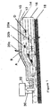
- FIG. 1 A schematic representation of void generation and dissipation is shown in Figure 1 .
- a vacuum bag or member 10 overlays a breather layer 12, which overlaps a release film 14.
- Release film 14 overlaps layers of pre-preg 16 which have been laid-up on tool or mould 18.
- pre-preg refers to pre-impregnated composite fibres where a pre-cured or partially cured matrix bonding material, such as epoxy, is already present. These usually take the form of a weave or are uni-directional. Gas filled voids may be formed within pre-preg 16, caused by for example entrapped air 20a, volatiles or off-gasing 20b, or leaks 20c in bag 10, tool or mould 18, etc.
- Gas transport may be co-planar within or interleaved between the various layers as shown by arrows A, or may be orthogonal to the layers as shown by arrows B. Collectively the gas migrates to the vacuum source, indicated in Figure 1 by arrow C leading to vacuum pump 22. Arrows D indicate void shrinkage or collapse.
- Each sensor package 28 is connected to a vacuum line or hose 30, for example is mounted in-line with a line or hose 30.
- Sensor package 28 may have a variety of individual sensors inside; for example: mass flow sensors, absolute pressure sensors, differential pressure sensors, temperature sensors, moisture sensors, valve position sensors, chemical sensors, or spectroscopic sensors such as fourier transform infrared spectroscopic sensors or near-infrared spectroscopic sensors.
- Vacuum hoses 30 are connected to vacuum pumps 22.
- a second vacuum system is provided which is independent of the gas conduits used for the primary vacuum process.
- the second vacuum system is mounted in a second, independent, fluid communication with the membrane 10a.
- the second vacuum system is used to locally reduce or increase, that is, to change the pressure in said membrane 10a so as to change the flow rate of the flow of gas through the gas conduits 30 for the primary vacuum process and thus so as to change the flow rate of the flow of gas interacting with the sensor.
- secondary membrane 10a is mounted locally over vacuum bag 10 and independently evacuated via secondary hose 30a by secondary vacuum pump 22a. Gas such as air between membrane 10 and 10a flows in direction E in the case where the pressure between membrane 10 and 10a is reduced to affect the rate of flow in direction C through hose 30.
- each sensor package 28 communicates, via wired or wireless transmission, singly or as a group, with a back-end database 32 that stores all the information from the sensors.
- Back-end database 32 is seen in Figure 2a interrogated by one or more front-end applications for real-time information during the manufacturing process as well as for historical and data mining information, as hereinafter described, after a given part 26 is made.
- the front-end application can run on the same computer as the back end application and/or a front end computer 34 or multiple other computers.
- the front end application and the back end application may be separate applications, a single combined application, or a mixture thereof.
- a roamer mobile computer 36 or other portable data processing device may be carried by one or more workers so that the worker(s) receive feedback or provide input to or to control the system as they work their way around a part 26 looking for leaks.
- a device may be a wireless device including but not limited to a cell phone, tablet, mobile computer, etc. to display data such as values, plots, diagrams, images sent by the system, to provide input to the system, and to control the behaviour of the system start/stop of data collection, to change system operating parameters, etc.
- the amount of interactivity between the system and the wireless device varies with the capability of both the device and the system.
- sensor packages 28 may also be mounted in the breather 12, such as by means of a breather mat that has multiple passages, wherein flow sensors may be mounted in the passages. The mat is placed between the part and vacuum ports providing under-bag flow sensing.
- sensor package(s) 28 may be part of the tool or mould (so-called “smart” tooling), so that manifold style vacuum lines may be set up, or may be part of a "smart” manifold such as seen by way of example in Figure 4 .
- Smart tooling allows the moulds or tooling 18 to have multiple vacuum port locations while vacuum is pulled from one location.
- the sensors packages may measure gas transport into these cavities.
- smart manifold 29 includes a housing 29a which may be compartmentalized pr modular for having sensor packages 18 associated with each flow inlet 29b.
- Hose 30 connect to inlets 29b.
- the sensor packages 28 may include inlet filters 29c and outlet filters 29d (seen in Figure 3 ), sensors such as described herein below, including for example flow sensors, pressure sensors, etc., and may also advantageously include bypass valves as described below, data acquisition modules, communication modules and a battery or batteries to provide power to the modules.
- Flow from inlets 29c exits from one or more flow outlets 29e.
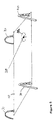
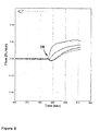
- FIG. 5 An example of leak localization is described below using the test arrangement illustrated in Figure 5 , wherein a simulated vacuum bag 10 was sealed down onto a test bench (not shown). Vacuum hoses 30 were coupled to the four corners of the simulated vacuum bag 10 and a vacuum was applied to hoses 30. As seen in Figure 6 the mass flow rate for each of the four hoses 30 was monitored and plotted as the volume between the simulated vacuum bag 10 and the test bench was evacuated. The flow-rate over time plot of Figure 7 confirmed that there were no leaks, as the mass flow rate fell to zero and remained at zero. A pin hole was then made in the simulated vacuum bag 10 so as to create a pinhole leak 38 of approximately two inches of mercury pressure drop per minute.
- pinhole leak 38 was immediately sensed by the flow sensors on each of the four hoses 30, with flow being indicated from all four vacuum lines 30 commencing at substantially the same time.
- Figure 9 shows the results of the software (discussed below) predicting that the location of leak 38 was within area 38a. As may be seen, the predicted location of the leak was very close to the known location of the actual leak 38. With sufficient sensor packages 28 and vacuum lines 30, multiple simultaneous leaks may be identified and located.
- Defect information may be used to identify not only gas based defects and leaks, but also features such as bag bridging, misalignment of moulds or tooling, caul plates, and other features, as well as excessive gaps and other unacceptable features.
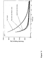
- Inline mass flow sensors 40 constrict the flow significantly, and therefore may create unacceptable pressure drops across the sensor at high flow rates. This has two distinct disadvantages: (a) longer evacuation times as illustrated in Figure 10 , and (b) unacceptable pressure increase across the sensor in the case of a leak as illustrated in Figure 11 . Therefore, a bypass which includes a bypass valve 48 such as seen in Figure 12 may be advantageously employed in certain embodiments of sensor package 28. At high gas flow rates, the bypass valve 48 opens, and the pressure drop across the sensor package is acceptably small as seen in Figures 10 and 11 . Gas flow rates may still be measured by careful calibration and use of both the gas flow rate measurement and the differential pressure loss across the sensor package. At low gas flow rates the bypass valve 48 closes, and all of the gas flows through the gas mass flow sensor 40.
- bypass valve 48 may use one or more magnets 50 or other source(s) of a magnetic field to preload a reed 52, shown in the open position, that, when in its closed position, closes the bypass valve 48.
- bypass valve 48 has a housing or body 54 having an inlet 54a and an outlet 54b.
- a conduit 54c extends between the inlet and outlet.
- Conduit 54c has magnets 50 mounted at the upstream side of conduit 54c.
- Reed 52 and flexible stopper 56 overlay the downstream end of conduit 54c so as to close conduit 54c when valve 48 is closed.
- Stopper 56 and/or reed 52 are made of or contain material which is magnetically attracted to magnets 50, so that when stopper 56 and reed 52 are in their closed position overlaying conduit 54c so as to close off flow therethrough, a threshold pressure must be reached in inlet 54a to overcome the magnetic latching of stopper 56 and reed 52 over conduit 54c. Once the magnetic latch is overcome by the pressure in inlet 54a reaching the threshold pressure for the latch to open, flexible reed 52 and stopper 56 abruptly swing or bend to their open position illustrated, that is, a substantially fully open position thereby allowing gas flow through conduit 54c.
- the reed valve is sized to achieve the desired opening and closing behaviour.
- the crisp opening and closing of reed 52 is determined by the magnetic field and strength of the magnets 50, and by the flexibility of the reed.
- An electro magnet may also be used to allow the reed valve's behaviour to be actively controlled.
- the reed may be elastically loaded when in it's closed, no flow condition, so as to snap open once released.
- Flow sensors, pressure sensors, differential pressure sensors, temperature sensors, and/or a valve position sensor may be usefully included. Stop 56 is optional, and is used to limit the deflection of reed 52.
- Reed 52 is advantageously of light weight construction so as to minimize variation in valve behaviour with orientation due to gravity, so that valve performance is independent of the spatial orientation of the sensor package.
- the reed's free end may be curved, for example to assist in loading reed 52 elastically when in its closed position.
- sensors are protected from high pressure by being placed inside a sealed unit, and/or are partially protected from high temperature by being placed inside an insulated unit 60. Electronics may be similarly protected, if necessary, from pressure and temperature.
- FIG. 15a another option is to integrate flow sensors 40 with the vacuum port 70.
- directional radial flow sensors 40b which may identify the direction from which the gas flow originates, are mounted into a vacuum port housing 70a.
- a vacuum port chuck 70b mounts onto housing 70a so as to support a vacuum hose 30 mounted thereon and so as to seal bagging material 10 therebetween.
- Flow sensors 40 mounted in sensor packages 28, may as seen in Figure 16 be installed directly on, or within, the tool or mould 18 for ease of use.
- bagging material 10 overlays a part 66 on tool or mould 18 and is sealed to tool or mould 18 by a bead of sealant 68.
- Vacuum ports 18a are formed in tool or mould 18.
- Sensor packages 28 are mounted in fluid communication with vacuum ports 18a.
- a manifold 74 is mounted to sensor packages 28 so as to connect sensor packages 28 and vacuum ports 18a with vacuum line 30.
- system level software flow 300 includes, in order of operation, secure login 302 which provides access to main menu 304.
- Main menu 304 provides access to system configuration 306, historical activities 308, or new activity 310.
- Historical activities 308 gives access to historical data actions 312 which itself provides for reporting 314 or data export 316.
- New activity 310 gives access to activity configuration 318, which gives access to activities 320.
- Activities 320 gives access to signal or data monitoring 322, leak localization 324, trend analysis or fingerprinting 326, real-time process simulation 328, or process control 330.
- the feedback as described throughout this specification may, at least in part, be based on, or correspond to, the spatial relationship between the user/worker/inspector/ receiving the feedback and the membrane or mould as the case may be.
- leak localization 324 may include using live flow and pressure data 408, and the geometry and sensor location information 410 to predict in step 412 the locations of one or more leaks in one or more dimensions.
- Feedback is provided in step 414 using plots, maps, schematics, images, animations, projections, sounds, haptics, etcetera or any combinations thereof to show the predicted leak locations.
- trend analysis and finger printing 326 may include live (that is, real-time) flow, pressure, etc. data 502, geometry and sensor location data 504, and historical data 506 from similar activities.
- the data is analyzed in step 508 to combine historical data and live data to develop trends and fingerprints for classes of analyses, such as finite element analysis.
- Feedback is provided in step 510 of live data, historical envelopes, trends, fingerprints, etc. using plots, maps, schematics, images, animations, projections, sounds, haptics, etc. or any combination thereof.
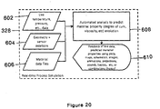
- real-time process simulation 328 may include live temperature, pressure, etc. data 602, geometry and sensor location data 604, and/or material data files 606.
- the data is analyzed in step 608 to automatically predict material property evolution, for example the evolution of the degree of cure, viscosity, etc.
- Feedback is provided in step 610 of live data, predicted material properties using plots, maps, schematics, images, animations, projections, sounds, haptics, etc. or any combinations thereof to show the evolution of the material properties.
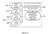
- process control 330 may include live flow, pressure, temperature, etc. data 702, geometry and sensor location data 704, process control parameters 706 and real time process simulation 328 so as to provide automated control of actuators and other process control devices in step 708 based on measurement devices, trend analyses and process simulation.
- Feedback is provided in step 710 of the process control state, actuator status, process control values, etc. using schematics, tables, sounds, images, animations, projections, haptics, etc. or any combinations thereof.
- system architecture 800 includes back end 802.
- Back end 802 includes back end database 32.
- Back end database 32 communicates via appropriate communications protocols as would be known by one skilled in the art, with a dispatcher or multiple dispatchers 804 and with multiple front ends 806.
- Front ends 806 may include front ends 34 or 36 illustrated in Figure 2a .
- Dispatchers 804 communicate with electronic packages 808 which receive data from sensor packages 810, which may include sensor packages 28.
- the system level architecture described may include:
- computational fingerprinting 900 includes collecting geometry and sensor location data 902, and material information 904, and processing that information to create a grid of representative virtual leak locations in step 906.
- step 908 for each virtual leak location the flow values are calculated at sensor locations for a known virtual leak rate using a computational method such as finite element analysis.
- step 910 the flow value at the virtual leak and virtual sensors are calculated and stored as a "fingerprint”.
- steps 908 and 910 are iterated in loop 914 until each leak location has been simulated.
- live flow data 916 is used in comparison step 918 to find the closest fingerprint that corresponds to the currently measured flow data collected in step 916, so as to identify the expected leak location by the matching of the live flow data to the closest corresponding fingerprint.
- Feedback is provided in step 920 using plots, maps, schematics, images, animation, projections, sounds, haptics, etc., or combinations thereof.
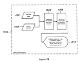
- Line leak prediction 1000 is illustrated in the flow chart of Figure 24 .
- Live flow data is collected in step 1002.
- Sensor location data is collected in step 1004.
- curves are fitted to the live flow data and sensor location data from steps 1002 and 1004 respectively.
- the peaks of the curves fitted in step 1006 are identified and used to predict leak locations.
- Feedback is provided in step 1010 using plots, maps, schematics, images, animations, projections, sounds, haptics, etc., or combinations thereof.
- Analytical triangulation 1100 is illustrated in the flow chart of Figure 25 .
- Analytical triangulation includes collecting live flow data in step 1102 and collecting geometry and sensor location data in step 1104.
- step 1106 all possible pairs of sensors are determined from the data from step 1104.
- step 1108 for each pair of sensors determined in step 1106, the apex of all possible triangles (so-called "apex sets") are determined by setting the ratio of the sides of the triangles to be the same as the ratio of the measured flows from step 1102.
- step 1110 for each pair of "apex sets" the point of intersection is determined, or where there is no intersection, the mid point of the line joining the points of closest approach is determined so as to indicate possible leak locations.
- Test-based fingerprinting 1200 is illustrated Figure 26 .
- Actual geometry and sensor location data from step 1202 is used in step 1204 to lay up and bag a representative part 26 so as to create in step 1206 a grid of representative leak locations.
- step 1208 a small but measurable leak is created at each representative leak location from step 1206.
- the measured leak and flow sensor data from the small leaks created in step 1208 are recorded and stored in step 1210 so as to create a "fingerprint".
- the representative leak created in step 1208 is sealed and if all of the representative leak locations created in step 1206 have not been tested then loop 1214 iterates the testing to step 1208 for the creation of the next small but measurable leak at the next representative leak location from the grid of representative of leak locations created in step 1206.
- Live flow data collected in step 1216 is used in step 1218 once all of the testing iterations of steps 1208-1214 have been completed, so as to compare the data from step 1216 with the fingerprints recorded and stored in step 1210 so as to determine in step 1218 which is the closest fingerprint that corresponds to the currently measured flow data and thereby identify the expected leak location.
- Feedback is provided in step 1220 using plots, maps, schematics, images, animations, projections, sounds, haptics, etc. or combinations thereof.
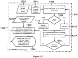
- Leak identification optimization 1300 is illustrated in the flow chart of Figure 27 .
- Geometry and vacuum lines and flow sensors data is collected in step 1302 and used in step 1304 to create permutations of vacuum line valve conditions.
- step 1306 for each permutation in step 1304 the conditions for each valve are set. If for a particular permutation, the valve condition, as determined in step 1308, is closed, then the vacuum/pressure is measured in step 1310, and if the valve condition is open, gas is drawn in step 1312. Following steps either 1310 or 1312, the flow sensor data is recorded and stored in step 1314.
- step 1316 If, as determined in step 1316, all of the permutations created in step 1304 have not been tested, then loop 1318 returns to step 1306 so as to set the condition for each valve in the next permutation according to the permutations created in step 1304.
- Data from a previously established leak fingerprint data base such as described above, is retrieved in step 1320 and, when in step 1316 it is determined that all of the permutations have been tested, then in step 1322 the flow sensor data recorded and stored in step 1314 is compared to the data retrieved in step 1320 so as to find the closest fingerprint that corresponds to the aggregate flow data to identify the expected leak location.
- Feedback is provided in step 1324 using plots, maps, schematics, images, animations, projections, sounds, haptics, etc. or combinations thereof.
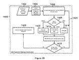
- Leak fingerprint database optimization 1400 is illustrated in the flow chart of Figure 28 .
- Geometry and vacuum lines and flow sensors data is collected in step 1402 and used to created permutations of vacuum line valve conditions in step 1404.
- the condition for each valve is set in step 1406.
- the valve condition for each permutation is determined in step 1408, and if the valve condition for that permutation is closed then vacuum/ pressure is measured in step 1410. If the valve condition is vented then a controlled leak (for example, a small, measurable leak) is identified in step 1412. If the valve condition is open then gas is drawn in step 1414.
- the flow sensor data is recorded and stored.
- step 1418 it is determined whether each permutation created in step 104 has been tested, and if not, loop 1420 returns to step 1406 so as to set the condition for each valve for the next permutation in the permutations created in step 1404. If in step 1408 it is determined that each of the permutations has been tested then a leak fingerprint database is created or augmented in step 1422.
- Vacuum line and flow sensor location optimization 1500 is illustrated in the flow chart of Figure 29 .
- Geometry and vacuum line and flow sensor data is gathered in step 1502.
- the fingerprint database is analyzed so as to examine the sensitivity of flow sensor and vacuum line locations.
- the vacuum lines and flow sensors are identified that can be removed with minimal impact on the effectiveness of the system.
- the regions are identified where the addition of vacuum lines and flow sensors may increase the effectiveness of the system.
- each vacuum line may either be drawing vacuum, closed, or vented to the atmosphere (thus allowing air to come in).
- the local gas permeability's of the assembly may be evaluated, and used to calibrate the localization/triangulation/fingerprinting methods previously described.
- each gas conduit or gas port has a corresponding unique identifier so as to correlate the gas flow data with said corresponding unique identifier.
- the unique identifier may identify a unique location and may be chosen from the group which includes, for example, barcode, or radio-frequency identification.
- At least one gas conduit may be adapted to carry power and/or data.
- the meaningful and efficient way to determine the output from the system is by the use of a digital processor such as a computer.
- a digital processor is used to transform the sensor data for example into feedback that locates gas-based defects identified herein.
Landscapes
- Engineering & Computer Science (AREA)
- Mechanical Engineering (AREA)
- Chemical & Material Sciences (AREA)
- Composite Materials (AREA)
- Physics & Mathematics (AREA)
- General Physics & Mathematics (AREA)
- Examining Or Testing Airtightness (AREA)
Description
- This disclosure generally relates to methods for collecting and interpreting industrial process data, and more specifically to a system and method using in situ sensors to collect data during composite manufacturing, including preparatory bagging and sealing, as well as the processing inside an autoclave, oven, press or other composite manufacturing system.
- In composites manufacturing, the object is to produce the highest quality part possible. A common defect in composites is the presence of voids and porosity. Voids and porosity can be minimized by minimizing the sources of gas leading to such voids and porosity, and maximizing the removal and reduction of gas volume. Sources of the gas include but are not necessarily limited to entrapped air during preparation of the part, entrapped moisture, and generation of gases as a by-product of the chemical reactions during cure of the matrix, and leaks during the manufacturing process. Regardless of the method of composites manufacturing, the removal of gas by the application of vacuum to the part is a well-established procedure. It is generally accepted that a sufficient vacuum must be pulled on a part to achieve good quality, and considerable time and effort is expended in managing and controlling the vacuum pulled on a part.
- Current methods for assessing the vacuum pulled on a part in the most part involve the measurement of the gauge or absolute pressure in the vacuum lines. The lower the measured pressure, the better the vacuum pulled on the part. As it is known that the pathways into the part and within the part may be blocked, a variety of methods are used to ensure that there are open pathways to every position in the part. Methods include but are not limited to multiple vacuum lines, so-called 'breather' fabrics, and specialized raw composite material forms such as so-called 'out-of-autoclave' pre-impregnated materials.
- Leaks are a particularly common source of quality problems. Sources of leaks include but are not limited to improper sealing of seams between mould segments, improper sealing of flexible vacuum bags over the part and mould, puncturing of the flexible vacuum bag, failure of rubber and other hollow inserts, and failure of the solid mould or semi-flexible caul plate. Leaks can be present from the beginning of the manufacturing process, or can occur later in the process, for example when heating or pressurizing the assembly inside an autoclave, oven, or press.
- The most common methods for detecting the presence of leaks, or alternatively confirming the vacuum integrity of the system, consist of shutting off the evacuation of the assembly, and monitoring the rise of pressure as air leaks into the assembly. An increase in pressure less than a prescribed amount, over a prescribed time, is considered to be indication of adequate vacuum integrity. This procedure is time-consuming, particularly if a leak is found to be present, and the procedure must be repeated after every attempt to fix the leak. Consequently the conventional leak detection method may take many hours to locate a single leak, causing significant and costly manufacturing downtime. Furthermore, the procedure is sensitive to the size of the part, and the larger the part, the less sensitive the procedure. Other methods, including sensitive coatings on the vacuum bag, and the use of mass flow sensors for vacuum assisted resin transfer moulding, have also been evaluated. Additionally, particularly in a very large part, there is currently no simple way to identify even the approximate location of the leak, other than by compartmentalizing the part. Outside of composites manufacturing, gas flow rates out of a system are often monitored and used instead of, or with, gas pressure measurements. A fundamental problem to date has been that the relationship between gas pressure and gas flow rates is complex.
- Accordingly, there is a need for a system that provides continuous usable information on the evacuation state of the assembly (including during cure), and in the case of a leak, allows for immediate and continuous monitoring of the leak, including preferably guidance as to the location of the leak and its significance.
- In the prior art applicant is aware of United States Patent No.
3,818,752 which issued to Lindeberg on June 25, 1974 for A Method And Apparatus For Testing Tightness. Lindeberg describes the use of pressure differential across a valve for detecting leaks in an enclosed volume wherein, after the pressure difference across the valve falls below a predetermined value, any further flow that is sensed is indicative of a leak in the volume. Lindeberg also discloses that if a leak is detected, the location of the leak may be obtained by smearing the volume tank with a soap solution or the like so as to provide an indication of where air or liquid is forced out of the tank. - Applicants are also aware of United States Published Patent Application, Publication No.
US2008/0252470 , which published on October 16, 2008 in the application of Taricco entitled Leak Detectors and Leak Detection Methods. Taricco describes that it may be necessary in the field of composite structure manufacturing to leave a pressure or vacuum on a system for a prolonged period without loss of pressure or vacuum as a leak test. A vacuum sensing and alarm system is disclosed by Taricco as being used together with a pressure gauge, separate or integral with the system, wherein the pressure gauge would confirm that the pressure or vacuum remained within acceptable limits throughout the prolonged period. An adjustable pressure of vacuum switch detects a more rapid leak. Alternatively the pressure switch may be replaced by a pressure transducer. - Applicants are also aware of United States published patent application, Publication No.
US2009/0273107 which published November 5, 2009 in the application of Advani et al. entitled System and Method Of Detecting Air Leakage in A VARTM Process. Advani et al. disclose using heated air and distributing the heated air along an interface along a bagging film and the surface of a mould so as to locate leaks in the bagging film by determining the temperature distribution of the air along the interface. Advani et al. describe that during the VARTM Process that checking the vacuum level is standard procedure especially when a large part is being made, as any air leakage will decrease the part quality. Advani et al. further disclose that the primary leak isolation method which is conventionally used is performed by vacuuming the air out of the mould and if the vacuum pressure level has not decreased after a predetermined amount of time that the mould is considered to be free of air leaks, but that the disadvantage of this method is that it is only able to indicate if there is or is not a leak and does not specify the location of any leak. Thus Advani et al. teach using thermal leak detection employing a heat gun to warm air and introduce that warm air to potential leak areas around the mould, and that the method may also utilize a infrared camera to capture thermal images of the tested areas. - Applicants are also aware of United States published patent application, Publication No.
2010/0326584 , which published on December 30, 2010 in the application of Schibsbye entitled Method and Apparatus for Detecting Leak in A VARTM Process. Schibsbye discloses that during producing a composite structure, and in particular during the evacuation process, an air flow level through at least one vacuum outlet is measured. Schibsbye describes a method for manufacturing a composite structure which includes fibre reinforced material using a vacuum assisted resin transfer moulding process wherein the fibre material is impregnated with liquid resin. Schibsbye identifies a problem in the VARTM process wherein dry spots where the fibre material is not impregnated with resin provide areas for air pockets which need to be repaired. Schibsbye also identifies that leaks in the sealing between the mould part and the vacuum bag and/or in the vacuum bag itself may lead to problems with effectively evacuating the mould cavity or effectively filling the mould cavity with resin, thereby also being a cause of dry spots. Schibsbye states that even very small holes can cause these problems, and as fibre composite structures, such as wind turbine blades may have a length of 60 meters and have a surface area of several hundred square meters, that it can be very time consuming to find the leaks thereby prolonging the overall production time of the laminate structure. - Consequently, Schibsbye proposes the use of a gas mass flow sensor connected to an inlet tube in order to measure the gas flow through the interior of the container. A pressure transducer is provided so as to monitor the vacuum level, that is, the pressure in the interior of the sealed container and consequently the vacuum level of the mould cavity or the individual mould cavity sections. If it is determined that the gas flow for a given apparatus exceeds a predetermined threshold value for a given vacuum level, then the operator knows that a leak exists in the mould cavity, and if only a single apparatus identifies such a leak then it can be concluded that the leak exists in the corresponding mould cavity section. Schibsbye teaches that by using flow sensors an operator of the VARTM process can identify leaks and the location of such leaks faster.
- Finally, applicants are aware of three United States published applications having a common inventor; namely, Miller, and a common assignee; namely, the Boeing Company. Thus in United States published patent application, Publication No.
US2008/0148817, published June 26, 2008 , in the application of Miller et al. entitled Leak Detection In Vacuum Bags, the use of a leak detection film covering the inside face of the vacuum bag is disclosed wherein the film includes a gas permeable binder carrying oxygen sensitive material that changes in physical appearance at the location of an air leak. Miller et al. discuss that flexible vacuum bags are used in manufacturing such as the fabrication of composite structures and the bonding of parts, for example, in the aerospace industry where vacuum bags may be used in vacuum bag moulding wherein a flexible bag is placed over a part pre-form and sealed along a mould flange. Air is evacuated and liquid resin is drawn into the bag which is infused into the pre-form so that any leaks in the vacuum bag may allow air to enter and form bubbles in the resin matrix resulting in an unacceptable amount of porosity in the matrix. - Thus Miller et al. propose that leaks may be detected in gas impermeable, transparent membranes used to maintain a pressure differential by the use of a gas permeable film or coating placed on or near the membrane that emits or reflects light of various wavelengths in the area of the leak or pressure gradient so as to provide rapid visual detection of air leaks in vacuum bags. The gas sensitive material changes in appearance in response to exposure to gas caused by a leak in the bag.
- In United States published patent application, Publication No.
US2010/0170326, published July 8, 2010 , in the application of Miller et al. entitled Leak Detection In Composite Tools, which is a continuation-in-part of the aforementioned application to Miller et al., Miller et al. state that, although a vacuum integrity test may provide a means to indicate the presence of a leak, the vacuum integrity test may lack the capability to allow for identifying the location of leaks on the tool, and that another draw back is that the vacuum drop check may not provide an indication as to whether the leak is in the tool, in the vacuum bag, or in the seal that seals the vacuum bag to the tool. Miller et al. propose the use of a breather layer interposed between the tool and the leak detection film for facilitating air flow therebetween. - In United States published patent application, Publication No.
US2011/0259086, published October 27, 2011 , in the application of Miller et al. entitled Leak Detection in Vacuum Bags, a device is described for indicating the location of an air leak in a vacuum bag used to process composite parts. The device includes a layer of material on the inner face of the bag that changes in appearance due to an oxidation-reduction reaction in the areas of the layer exposed to oxygen caused by a leak in the bag. Miller et al. describe the use of an ink or dye which is applied to the inner face of the vacuum bag film, wherein once a vacuum is drawn within the bag causing the air pressure within the bag to drop which then allows the atmospheric pressure to push the bag down onto the layup and to compact the layup, the colorimetric material is activated by directing ultraviolet light through the transparent vacuum bag and onto the ink rendering the ink reactive to oxygen so that the ink changes in color when exposed to oxygen due to a leak. - European Patent Publication No.
2 105 285 A2, published on September 9, 2009 describes a system and method for collecting data during vacuum molding of a composite partusing a mold including an air tight, flexible membrane sealed to a tool. The system comprises a plurality of MEMS sensors coupled with the interior of the mold at different locations over the part. Each of the sensors produces signals related to a process parameter, such as pressure within the bag, that is sensed at the location of the sensor. The sensors are connected to a data collection device located close to the mold. - In the present invention, one or more in-situ thermal mass flow sensors are provided. Each may be packaged with one or more other sensors into a 'sensor package', to monitor gas flow in composite manufacturing processes, including but not limited to autoclave and oven manufacturing of pre-impregnated material structures made of both thermoset and thermoplastic materials; and resin infusion or resin transfer moulding processes. For example, multiple sensor packages may be used to sense flow rates at multiple locations, such as within the breather, vacuum ports, vacuum hoses, and bladder vents. In one embodiment the invention reduces the ambiguity and cost of leak check data based on pressure rise measurements or other methods, allow for identification of the location of the leak, and speeds up the process of leak detection and repair. Additionally, the flow rate profiles, including the shape of the evacuation profile, and the integral of the flow rate, i.e., the total volume of gas evacuated, may be used to evaluate the consistency of the part manufactured relative to the general population of parts manufacture, allowing for the use of statistical and data mining techniques to assess production. Additional capabilities in terms of identification of moisture outgassing and other features are further summarized and described below.
- In summary, the present invention may be characterized, in one aspect, as
a process for locating a porosity-causing gas leak during manufacturing of a composite part, the process comprising: - engaging the composite part with a gas impermeable membrane so as to contain the composite part within the membrane and define a flexible non-compartmentalized single volume between the composite part and the membrane,
- fluidly connecting at least one gas conduit to the membrane for flow of gas through the membrane,
- mounting in co-operation with the membrane a plurality of sensors, wherein said plurality of sensors are mounted in a spaced apart array relative to said part and in fluid communication with at least said single volume,
- evacuating said single volume through the at least one gas conduit, using the plurality of sensors for detecting and measuring at least one characteristic of gas flow, at least during said evacuating, and at least in the single volume,
- generating gas flow data corresponding to said detecting and measuring of said at least one characteristic of gas flow, and
- computing gas leak information from said generated gas flow data by;
- determining combinations of pairs of sensors by employing a geometry of the composite part and locations of the plurality of sensors relative to the composite part
- for each pair of sensors determining apex sets for all triangles formed from each pair of sensors, each said triangle having a base leg that extends to and between the pair of sensors and an apex defined at an intersection of remaining two legs of said triangle, wherein the remaining two legs have first and second lengths, respectively in proportion to corresponding first and second gas flow rates at the pair of sensors, respectively;
- for each pair of said apex sets determining:
- a) a point of intersection between said apex sets, or
- b) where there is no said point of intersection, a mid-point of a line joining points closest to one another between all of said apexes to provide possible leak locations.
- Preferably, the process includes relaying to a user, feedback of said gas leak information, wherein said relaying of said feedback includes displaying said gas leak information to the user while the user is inspecting said composite part and said membrane.
- Further, preferably, the process includes computing an average of said possible leak locations to thereby predict a single leak location.
- Suitably, the plurality of sensors includes at least one sensor from the group consisting of: radial flow direction sensors, humidity sensors and spectroscopic sensors.
- Preferably, the process includes mounting at least one of said plurality of sensors to said at least one gas conduit.
- Advantageously, said plurality of sensors includes at least one mass flow sensor, at least one pressure sensor and at least one differential pressure sensor.
- In one embodiment the process includes packaging the plurality of sensors into a sensor package and said sensor package includes at least two of said plurality of sensors within said package.
- Preferably, the process includes further packaging the plurality of sensors into a sensor package and wherein said sensor package includes said at least one mass flow sensor, said at least one pressure sensor and said at least one differential pressure sensor within said package.
- Further, preferably, at least one of said plurality of sensors is mounted in said volume.
- Advantageously the process includes providing a breather material in said volume between said composite part and said membrane, and wherein said breather material has substantially uniform permeability.
- In a further embodiment, the process includes providing a flow bypass having a resilient flexible bypass valve member and cooperating with at least one of said plurality of sensors to reduce a pressure drop across at least one of said plurality of sensors.
- In a further embodiment, the process includes at least one of said plurality of sensors being mounted on or in at least one of the group comprising: said at least one gas conduit, gas ports, a gas breather, a mat having sensor flow passages, a manifold, a mould or tool.
- Preferably, said bypass valve member includes a reed means.
- Further, preferably, said reed means is biased between open and closed positions, according to a pre-determined pressure threshold, by a gas pressure of said gas flow.
- Suitably, said pressure threshold is a differential pressure threshold of a differential pressure across an associated sensor of said plurality of sensors.
- Preferably, said bypass reed means is maintained in said closed position by a magnetic field.
- In a further embodiment, the process includes providing a plurality of gas conduits spaced apart and mounted on, in fluid communication through, said membrane, and the process further includes optimizing the plurality of sensors on said gas conduits for use with each type of uniquely shaped said composite part, wherein said optimizing includes applying said evacuation or pressurization of said volume respectively during said vacuum or pressurization process via said gas conduits, and said detecting and measuring said at least one characteristic of mass flow rate and/or pressure in said gas conduits, and subsequent corresponding said determination of said gas leak information, is detected and measured during when at least a first gas conduit of said gas conduits are biased into an open-to-gas flow condition and at least a second gas conduit of said gas conduits are biased into a closed-to-gas flow condition.
- Preferably, said biasing of said at least first and at least second of said conduits into said open-to-gas flow and said closed-to-gas flow conditions respectively is cycled through all of said gas conduits in a pattern of opening and closing of said gas conduits to said gas flow, wherein said pattern provides said opening and closing in substantially all permutations as between substantially all combinations of said opening and closing of said gas conduits.
- Preferably, said pattern is predetermined.
- In a further embodiment, the process includes a flow bypass mounted in fluid communication with said at least one gas conduit, and separate from, so as to not be mounted to said plurality of sensors.
- In a further embodiment said reed means includes a curved reed, and said curved reed is curved so as to elastically pre-load said reed when in said closed position.
- In a further embodiment at least one mass flow sensor is adapted to measure said flow of gas both into and out of said volume.
- In a further embodiment said at least one gas conduit includes a corresponding at least one inlet and/or outlet filter.
- In a further embodiment said leak detection said gas is other than air so as to perturb said gas flow data.
- In a further embodiment the process includes providing a second vacuum system independent of said at least one gas conduit for said evacuating process, said second vacuum system mounted in a second, independent, fluid communication with said membrane, and a further step of locally changing a pressure in said membrane so as to change a flow rate of said flow of gas through said at least one gas conduit and so as to said change said flow rate of said flow of gas interacting with said plurality of sensors.
- Preferably, said at least one gas conduit has a corresponding unique identifier for each conduit in said at least one gas conduit so as to correlate said gas flow data with said corresponding unique identifier and wherein the unique identifier is chosen from the group which includes: barcode, radio-frequency identification.
- Further, preferably, said at least one gas conduit is adapted to carry power and/or data.
- In a further embodiment, said spectroscopic sensors provide spectroscopic data for spectrographic analysis chosen from the group consisting of: fourier transform, infrared spectroscopy, and near-infrared spectroscopy.
- In a further embodiment, said at least one characteristic of said gas flow includes one or more characteristics from the group which further includes: a chemical content of at least one selectively detectable chemical, spectroscopically detectable content.
- In the accompanying Figures like reference numerals denote corresponding parts in each view, and wherein:
-
Figure 1 is a schematic representation of void generation and dissipation. -
Figure 1a is, in perspective view, an aircraft wing being manufactured by the composite manufacturing process. -
Figure 1b is the schematic ofFigure 1 showing the use of a secondary vacuum system. -
Figure 2 is a schematic representation of a basic embodiment of a gas response measurement system. -
Figure 2a is a diagrammatic representation of a computer system used in conjunction with the system ofFigure 2 . -
Figure 3 is a block diagram of one embodiment of a sensor package. -
Figure 3a is a block diagram of another embodiment of a sensor package. -
Figure 4 is, in perspective view, one embodiment of a smart manifold. -
Figure 5 illustrates the creation of a small pin hole leak on a simulated bag on a test bed. -
Figure 6 illustrates the immediate response from flow sensors (with bypass) during the evacuation of the test arrangement ofFigure 5 . -
Figure 7 illustrates the indication from the flow sensors that the simulated bag ofFigure 5 is fully evacuated and no leaks are present. -
Figure 8 illustrates that the leak created inFigure 5 is immediately sensed by the flow sensors. -
Figure 9 illustrates the prediction of the leak location inFigure 5 . -
Figure 10 is a graph of the effect of flow bypass on part pressure profile and speed of evacuation. -
Figure 11 is a graph of the effect of flow bypass on part pressure profile showing that without bypass the part pressure remains high in the presence of a large leak. -
Figure 12 is, in a cross sectional view, a schematic of a bypass having a reed valve. -
Figure 13 is a block diagram of a high temperature (and optionally high pressure) sensor package. -
Figure 14 is, in perspective view, an example of the use of a sensor package on an insert such as a bladder. -
Figure 15 is an example of the use of under-bag flow sensors. -
Figure 15a is an example of a vacuum port probe with directional radial flow sensors. -
Figure 16 is an example of sensors installed within the moulds or tooling. -
Figure 17 is a high level schematic of system operation illustrating software flow. -
Figure 18a is a schematic of system operation illustrating signal/data monitoring. -
Figure 18b is a schematic of system operation illustrating leak localization. -
Figure 19 is a schematic of system operation illustrating trend analysis and fingerprinting. -
Figure 20 is a schematic of system operation illustrating real time process simulation. -
Figure 21 is a schematic of system operation illustrating process control. -
Figure 22 is a schematic of system operation illustrating system architecture. -
Figure 23 is a schematic of computational fingerprinting. -
Figure 24 is a schematic of line leak prediction. -
Figure 25 is a schematic of analytical triangulation. -
Figure 26 is a schematic of test-based fingerprinting. -
Figure 27 is a schematic of leak identification optimization. -
Figure 28 is a schematic of leak fingerprint database optimization. -
Figure 29 is a schematic of vacuum line and flow sensor location optimization. - A schematic representation of void generation and dissipation is shown in
Figure 1 . A vacuum bag ormember 10 overlays abreather layer 12, which overlaps arelease film 14.Release film 14 overlaps layers ofpre-preg 16 which have been laid-up on tool ormould 18. As used herein, the term pre-preg refers to pre-impregnated composite fibres where a pre-cured or partially cured matrix bonding material, such as epoxy, is already present. These usually take the form of a weave or are uni-directional. Gas filled voids may be formed withinpre-preg 16, caused by for example entrappedair 20a, volatiles or off-gasing 20b, orleaks 20c inbag 10, tool ormould 18, etc. Gas transport may be co-planar within or interleaved between the various layers as shown by arrows A, or may be orthogonal to the layers as shown by arrows B. Collectively the gas migrates to the vacuum source, indicated inFigure 1 by arrow C leading tovacuum pump 22. Arrows D indicate void shrinkage or collapse. -
Figure 1a illustrates aworker 24 standing by a larger part 26; illustrated by way of example to be an aircraft wing, which is being formed by the composites manufacturing methods to which this specification is directed. Thus it will be understood that the parts 26 being formed may be very large and consequently have very large surface areas. - A diagrammatic layout of a basic embodiment of the hardware system according to aspects of the present invention is shown in
Figure 2 . Eachsensor package 28 is connected to a vacuum line orhose 30, for example is mounted in-line with a line orhose 30.Sensor package 28 may have a variety of individual sensors inside; for example: mass flow sensors, absolute pressure sensors, differential pressure sensors, temperature sensors, moisture sensors, valve position sensors, chemical sensors, or spectroscopic sensors such as fourier transform infrared spectroscopic sensors or near-infrared spectroscopic sensors.Vacuum hoses 30 are connected to vacuum pumps 22. - As seen in
Figure 1b , in a further embodiment, a second vacuum system is provided which is independent of the gas conduits used for the primary vacuum process. The second vacuum system is mounted in a second, independent, fluid communication with themembrane 10a. The second vacuum system is used to locally reduce or increase, that is, to change the pressure in saidmembrane 10a so as to change the flow rate of the flow of gas through thegas conduits 30 for the primary vacuum process and thus so as to change the flow rate of the flow of gas interacting with the sensor. Thus,secondary membrane 10a is mounted locally overvacuum bag 10 and independently evacuated viasecondary hose 30a bysecondary vacuum pump 22a. Gas such as air betweenmembrane membrane hose 30. - As seen in
Figure 2a , eachsensor package 28 communicates, via wired or wireless transmission, singly or as a group, with a back-end database 32 that stores all the information from the sensors. Two examples ofsensor packages 28 are shown inFigures 3 and3a . Back-end database 32 is seen inFigure 2a interrogated by one or more front-end applications for real-time information during the manufacturing process as well as for historical and data mining information, as hereinafter described, after a given part 26 is made. The front-end application can run on the same computer as the back end application and/or afront end computer 34 or multiple other computers. The front end application and the back end application may be separate applications, a single combined application, or a mixture thereof. In one embodiment, a roamermobile computer 36 or other portable data processing device may be carried by one or more workers so that the worker(s) receive feedback or provide input to or to control the system as they work their way around a part 26 looking for leaks. Such a device may be a wireless device including but not limited to a cell phone, tablet, mobile computer, etc. to display data such as values, plots, diagrams, images sent by the system, to provide input to the system, and to control the behaviour of the system start/stop of data collection, to change system operating parameters, etc. The amount of interactivity between the system and the wireless device varies with the capability of both the device and the system. - Although the illustration in
Figure 2 shows the schematics withsensor packages 28 only on thevacuum hoses 30 and/or ports, sensor packages 28 may also be mounted in thebreather 12, such as by means of a breather mat that has multiple passages, wherein flow sensors may be mounted in the passages. The mat is placed between the part and vacuum ports providing under-bag flow sensing. Alternatively, sensor package(s) 28 may be part of the tool or mould (so-called "smart" tooling), so that manifold style vacuum lines may be set up, or may be part of a "smart" manifold such as seen by way of example inFigure 4 . Smart tooling allows the moulds ortooling 18 to have multiple vacuum port locations while vacuum is pulled from one location. Furthermore, in parts with internal cavities or volumes such as bladders, the sensors packages may measure gas transport into these cavities. - As seen in
Figure 4 , smart manifold 29 includes ahousing 29a which may be compartmentalized pr modular for havingsensor packages 18 associated with each flow inlet 29b.Hose 30 connect to inlets 29b. The sensor packages 28 may includeinlet filters 29c andoutlet filters 29d (seen inFigure 3 ), sensors such as described herein below, including for example flow sensors, pressure sensors, etc., and may also advantageously include bypass valves as described below, data acquisition modules, communication modules and a battery or batteries to provide power to the modules. Flow frominlets 29c exits from one ormore flow outlets 29e. - The location of one or more leaks may be identified by triangulating measured flow rates from different vacuum lines 30. This works very well for many geometries but in very complex shapes this is more difficult, and therefore the simple triangulation may be augmented by fingerprinting and learning methods, discussed below, where the system is trained for a particular part, including the bagging and other relevant details. As described below, this learning may be empirical (by introducing known leaks), analytical (by doing computer simulations) or a combination.
- To provide additional leak localization capability, the positioning of the
vacuum lines 30 may be optimized for this purpose, by placing strategically placedvacuum lines 30 withsensor packages 28 to identify leak locations more accurately. Given that often the leak problem is due to hoses and fittings,multiple sensor packages 28 may also be placed along a vacuum path, from part 26 tovacuum pump 22. In a system withmultiple vacuum lines 30 equipped withsensor packages 28,vacuum lines 30 may be switched on or off individually or in groups, and the sensor data analyzed for patterns assisting in characterizing or localizing leaks. - An example of leak localization is described below using the test arrangement illustrated in
Figure 5 , wherein asimulated vacuum bag 10 was sealed down onto a test bench (not shown).Vacuum hoses 30 were coupled to the four corners of thesimulated vacuum bag 10 and a vacuum was applied tohoses 30. As seen inFigure 6 the mass flow rate for each of the fourhoses 30 was monitored and plotted as the volume between thesimulated vacuum bag 10 and the test bench was evacuated. The flow-rate over time plot ofFigure 7 confirmed that there were no leaks, as the mass flow rate fell to zero and remained at zero. A pin hole was then made in thesimulated vacuum bag 10 so as to create apinhole leak 38 of approximately two inches of mercury pressure drop per minute. As seen inFigure 8 ,pinhole leak 38 was immediately sensed by the flow sensors on each of the fourhoses 30, with flow being indicated from all fourvacuum lines 30 commencing at substantially the same time.Figure 9 shows the results of the software (discussed below) predicting that the location ofleak 38 was withinarea 38a. As may be seen, the predicted location of the leak was very close to the known location of theactual leak 38. Withsufficient sensor packages 28 andvacuum lines 30, multiple simultaneous leaks may be identified and located. - In the leak detection method, in one embodiment the gas is other than air so as to perturb the gas flow data. For example the gas may be CO2 or dry N2. In the latter, the sensor(s) would include a moisture sensor.
- The sensor packages 28 are unique as compared to the prior art of which applicant is aware in a number of ways:
With regard to the use of inlinemass flow sensors 40, appropriately selected and calibratedmass flow sensors 40 may be accurately used in a quantitative manner at the low absolute pressures (high vacuums) and high temperatures typically used in composites manufacturing. This is particularly true for composite manufacturing processes other than vacuum assisted resin transfer moulding (VARTM). - It is advantageous to include not only
mass flow sensors 40,pressure sensors 42 and, optionally,temperature sensors 44, but alsodifferential pressure sensors 46 to know how much resistance thesensor package 28 is introducing into the vacuum system. Block diagrams of twosuch sensor packages 28 are shown inFigures 3 and3a . The use of adifferential pressure sensor 46 ensures that the mere presence of thesensor package 28 does not harm the part. - The gas flow characteristics measured by
sensor packages 28 are used to generate the gas flow data, such as the shape of the curve or profile of the gas flow vs. time, or pressure vs. time, etc. graphs as seen for example inFigures 8 and10 respectively. The profiles are 'fingerprints' of a particular part 26 and can be used to identify, characterize, and rank the response of a given part 26, even before the part has been completely evacuated. Other data manipulation, including the integration of the gas flow history (with appropriate zeroing and base lining), may provide invaluable insight into the performance of the part during manufacturing. - Defect information may be used to identify not only gas based defects and leaks, but also features such as bag bridging, misalignment of moulds or tooling, caul plates, and other features, as well as excessive gaps and other unacceptable features.
- Inline
mass flow sensors 40 constrict the flow significantly, and therefore may create unacceptable pressure drops across the sensor at high flow rates. This has two distinct disadvantages: (a) longer evacuation times as illustrated inFigure 10 , and (b) unacceptable pressure increase across the sensor in the case of a leak as illustrated inFigure 11 . Therefore, a bypass which includes abypass valve 48 such as seen inFigure 12 may be advantageously employed in certain embodiments ofsensor package 28. At high gas flow rates, thebypass valve 48 opens, and the pressure drop across the sensor package is acceptably small as seen inFigures 10 and11 . Gas flow rates may still be measured by careful calibration and use of both the gas flow rate measurement and the differential pressure loss across the sensor package. At low gas flow rates thebypass valve 48 closes, and all of the gas flows through the gasmass flow sensor 40. - One bypass embodiment such as seen in
Figure 12 , and which is not intended to be limiting, may use one ormore magnets 50 or other source(s) of a magnetic field to preload areed 52, shown in the open position, that, when in its closed position, closes thebypass valve 48. In the illustratedembodiment bypass valve 48 has a housing orbody 54 having aninlet 54a and an outlet 54b. Aconduit 54c extends between the inlet and outlet.Conduit 54c hasmagnets 50 mounted at the upstream side ofconduit 54c.Reed 52 and flexible stopper 56 overlay the downstream end ofconduit 54c so as to closeconduit 54c whenvalve 48 is closed. Stopper 56 and/orreed 52 are made of or contain material which is magnetically attracted tomagnets 50, so that when stopper 56 andreed 52 are in their closedposition overlaying conduit 54c so as to close off flow therethrough, a threshold pressure must be reached ininlet 54a to overcome the magnetic latching of stopper 56 andreed 52 overconduit 54c. Once the magnetic latch is overcome by the pressure ininlet 54a reaching the threshold pressure for the latch to open,flexible reed 52 and stopper 56 abruptly swing or bend to their open position illustrated, that is, a substantially fully open position thereby allowing gas flow throughconduit 54c. Thus, once the pressure increases to a critical value due to too much flow,reed 52 releases frommagnet 50 and jumps to its open position, quickly dropping the pressure and resistance significantly. This is useful in a situation where there is a high flow rate from a leak, so that the sensor package does not introduce harm to the part by keeping the part pressure high. Additionally, although bulkier, it may be desirable to have active bypass control using solenoid valves (not shown). Other forms of bypass or bypass valves would also work as would be known to one skilled in the art. - In the bypass design of
Figure 12 , the reed valve is sized to achieve the desired opening and closing behaviour. The crisp opening and closing ofreed 52 is determined by the magnetic field and strength of themagnets 50, and by the flexibility of the reed. An electro magnet may also be used to allow the reed valve's behaviour to be actively controlled. Optionally, the reed may be elastically loaded when in it's closed, no flow condition, so as to snap open once released. Flow sensors, pressure sensors, differential pressure sensors, temperature sensors, and/or a valve position sensor may be usefully included. Stop 56 is optional, and is used to limit the deflection ofreed 52.Reed 52 is advantageously of light weight construction so as to minimize variation in valve behaviour with orientation due to gravity, so that valve performance is independent of the spatial orientation of the sensor package. Optionally, the reed's free end may be curved, for example to assist inloading reed 52 elastically when in its closed position. - By combining an appropriately calibrated moisture sensor 58 in either the
same sensor package 28 or in a coupled package, the water vapour mass flow rate may be calculated at the same time as the total gas mass flow rate. The history of the water vapour mass flow rate may be manipulated in the same manner as the manipulation of the total gas mass flow rate discussed above. The combined analysis of total and water vapour mass flow rate may be used in decision making as described in the system level descriptions below. Instead of moisture sensors 58, other chemical sensors, typically micro-electro-mechanical (MEMS) based, may also be used in similar fashion, providing additional data interpretation opportunities. - A high temperature, high pressure resistant sensor package 28' such as seen in
Figure 13 may be employed so that the measurements may be made during the manufacturing cycle, and not just during the bagging/preparation phase. The sensor packages 28 can be placed either outside the oven or autoclave, and thus see lower temperatures and/or pressure, or if suitably 'hardened', as for example in the embodiment of sensor package 28', may be placed inside the oven or autoclave, directly off the part 26, allowing for maximum accuracy and fidelity of information. One option is to insulate the signal conditioning from thermal effect by placing the signal conditioning outside the oven or autoclave. Another option is to use high temperature electronics. - In a moisture/gas flow design, a resistance or capacitance based humidity sensor may be mounted in line with the flow sensor.
- In the high temperature (and optionally high pressure) sensor package 28' of
Figure 13 , sensors are protected from high pressure by being placed inside a sealed unit, and/or are partially protected from high temperature by being placed inside aninsulated unit 60. Electronics may be similarly protected, if necessary, from pressure and temperature. - As seen in
Figure 14 , sensor packages 28 (shown in dotted outline), such as high temperature sensor packages 28'; if placed within the oven or autoclave during cure may be attached directly to inserts such asbladders 62. Amass flow sensor 40, and its associatedwiring 40a, is shown mounted in-line ontubing 64.Tubing 64 is sized to assist in providing laminar flow.Tubing 64 is mounted to port 62a onbladder 62. - As seen in
Figure 15 , individual flow sensors in the form oflocal flow sensors 72b mounted onflow belts 72 may be placed under the vacuum bag 10 (or inside the closed cavity as the case may be) to identify source and direction of gas flow. Thus as may be seen, baggingmaterial 10 overlays apart 66 on tool ormould 18 and is sealed to tool ormould 18 by a bead ofsealant 68. Vacuum is applied viavacuum hoses 30 attached to vacuumports 70. Abreather 12 andflow belts 72 are interleaved between baggingmaterial 10 and tool ormould 18.Wiring 72a extends fromflow belts 72 through baggingmaterial 10. - As seen in
Figure 15a , another option is to integrateflow sensors 40 with thevacuum port 70. Thus, directionalradial flow sensors 40b, which may identify the direction from which the gas flow originates, are mounted into avacuum port housing 70a. A vacuum port chuck 70b mounts ontohousing 70a so as to support avacuum hose 30 mounted thereon and so as to seal baggingmaterial 10 therebetween. -
Flow sensors 40 mounted insensor packages 28, may as seen inFigure 16 be installed directly on, or within, the tool ormould 18 for ease of use. Thus as may be seen, again baggingmaterial 10 overlays apart 66 on tool ormould 18 and is sealed to tool ormould 18 by a bead ofsealant 68.Vacuum ports 18a are formed in tool ormould 18. Sensor packages 28 are mounted in fluid communication withvacuum ports 18a. A manifold 74 is mounted tosensor packages 28 so as to connectsensor packages 28 andvacuum ports 18a withvacuum line 30. - By way of overview, one example, of a high level system level software flow is shown schematically in
Figure 17 , signal/data monitoring and leak localization is shown inFigures 18a and 18b respectively, trend analysis and fingerprinting inFigure 19 , real time process simulation (of particular value when the system is used during the cure process with elevated temperature and pressure) inFigure 20 , and process control (where the process can be modified to minimize the effect of any leak or other deviation from the normal manufacturing process) inFigure 21 . The system architecture is shown in greater schematic detail inFigure 22 . - In
Figure 17 , systemlevel software flow 300 includes, in order of operation,secure login 302 which provides access tomain menu 304.Main menu 304 provides access tosystem configuration 306,historical activities 308, ornew activity 310.Historical activities 308 gives access tohistorical data actions 312 which itself provides for reporting 314 ordata export 316.New activity 310 gives access toactivity configuration 318, which gives access toactivities 320.Activities 320 gives access to signal ordata monitoring 322,leak localization 324, trend analysis or fingerprinting 326, real-time process simulation 328, orprocess control 330. - As seen in
Figure 18a , the signal/data monitoring 322 may include live andhistorical sensor data 402 to providefeedback 404 which may include plots, maps, schematics, images, sound, haptics, etc. These are used in the determiningstep 406 to interrogate, analyze, probe, interact, cross-plot, etcetera, the data fromstep 404. - The feedback as described throughout this specification may, at least in part, be based on, or correspond to, the spatial relationship between the user/worker/inspector/ receiving the feedback and the membrane or mould as the case may be.
- As seen in
Figure 18b ,leak localization 324 may include using live flow andpressure data 408, and the geometry andsensor location information 410 to predict instep 412 the locations of one or more leaks in one or more dimensions. Feedback is provided instep 414 using plots, maps, schematics, images, animations, projections, sounds, haptics, etcetera or any combinations thereof to show the predicted leak locations. - As seen in
Figure 19 , trend analysis andfinger printing 326 may include live (that is, real-time) flow, pressure, etc.data 502, geometry andsensor location data 504, andhistorical data 506 from similar activities. The data is analyzed instep 508 to combine historical data and live data to develop trends and fingerprints for classes of analyses, such as finite element analysis. Feedback is provided instep 510 of live data, historical envelopes, trends, fingerprints, etc. using plots, maps, schematics, images, animations, projections, sounds, haptics, etc. or any combination thereof. - As seen in
Figure 20 , real-time process simulation 328 may include live temperature, pressure, etc.data 602, geometry andsensor location data 604, and/or material data files 606. The data is analyzed instep 608 to automatically predict material property evolution, for example the evolution of the degree of cure, viscosity, etc. Feedback is provided instep 610 of live data, predicted material properties using plots, maps, schematics, images, animations, projections, sounds, haptics, etc. or any combinations thereof to show the evolution of the material properties. - As seen in
Figure 21 ,process control 330 may include live flow, pressure, temperature, etc.data 702, geometry andsensor location data 704,process control parameters 706 and realtime process simulation 328 so as to provide automated control of actuators and other process control devices instep 708 based on measurement devices, trend analyses and process simulation. Feedback is provided instep 710 of the process control state, actuator status, process control values, etc. using schematics, tables, sounds, images, animations, projections, haptics, etc. or any combinations thereof. - As seen in
Figure 22 ,system architecture 800 includesback end 802.Back end 802 includesback end database 32.Back end database 32 communicates via appropriate communications protocols as would be known by one skilled in the art, with a dispatcher ormultiple dispatchers 804 and with multiple front ends 806. Front ends 806 may include front ends 34 or 36 illustrated inFigure 2a .Dispatchers 804 communicate withelectronic packages 808 which receive data fromsensor packages 810, which may include sensor packages 28. - The system level architecture described may include:
- 1) Use of flow and other data from multiple sensor packages, dimensions, and materials to predict the location of a leak.
- 2) Instantaneous feedback to the users of the system, using static and roaming devices and computers including visual, audio, tactile, or other sensory feedback, and may also include:
- a. the ability of the users to add comments to the system indicating what they are doing,
- b. the ability of the system to interface with other data acquisition and control systems performing other factory tasks (e.g. autoclave or oven controller).
- 3. Prediction of the type of leak(s) based on the flow behavior or signature, for example, in the bagging material, in the tool or moulds, in the mould or tool seal(s), in the bladder, etc.
- 4. Use of accumulated data from previously tested parts that allow the integrated and otherwise reduced data from a range of sensor packages to be used to characterize the evacuation behaviour of a given part against the database, leading to correlations with quality, herein referred to as one form of "fingerprinting".
- As illustrated in the flow chart of
Figure 23 ,computational fingerprinting 900 includes collecting geometry andsensor location data 902, and material information 904, and processing that information to create a grid of representative virtual leak locations instep 906. Instep 908 for each virtual leak location the flow values are calculated at sensor locations for a known virtual leak rate using a computational method such as finite element analysis. Instep 910 the flow value at the virtual leak and virtual sensors are calculated and stored as a "fingerprint". Atstep 912,steps loop 914 until each leak location has been simulated. Once each leak location has been simulated,live flow data 916 is used incomparison step 918 to find the closest fingerprint that corresponds to the currently measured flow data collected instep 916, so as to identify the expected leak location by the matching of the live flow data to the closest corresponding fingerprint. Feedback is provided instep 920 using plots, maps, schematics, images, animation, projections, sounds, haptics, etc., or combinations thereof. -
Line leak prediction 1000 is illustrated in the flow chart ofFigure 24 . Live flow data is collected instep 1002. Sensor location data is collected instep 1004. Instep 1006 curves are fitted to the live flow data and sensor location data fromsteps step 1008 the peaks of the curves fitted instep 1006 are identified and used to predict leak locations. Feedback is provided instep 1010 using plots, maps, schematics, images, animations, projections, sounds, haptics, etc., or combinations thereof. -
Analytical triangulation 1100 is illustrated in the flow chart ofFigure 25 . Analytical triangulation includes collecting live flow data instep 1102 and collecting geometry and sensor location data instep 1104. Instep 1106 all possible pairs of sensors are determined from the data fromstep 1104. Instep 1108, for each pair of sensors determined instep 1106, the apex of all possible triangles (so-called "apex sets") are determined by setting the ratio of the sides of the triangles to be the same as the ratio of the measured flows fromstep 1102. Instep 1110, for each pair of "apex sets" the point of intersection is determined, or where there is no intersection, the mid point of the line joining the points of closest approach is determined so as to indicate possible leak locations. Instep 1112 the average of the possible leak locations determined instep 1110 is used to predict a single leak location. The error from the scatter of possible leak locations determined instep 1110 is estimated instep 1114. Instep 1116 feedback is provided using plots, maps, schematics, images, animations, projections, sounds, haptics, etc., or combinations thereof. - Test-based
fingerprinting 1200 is illustratedFigure 26 . Actual geometry and sensor location data fromstep 1202 is used instep 1204 to lay up and bag a representative part 26 so as to create in step 1206 a grid of representative leak locations. In step 1208 a small but measurable leak is created at each representative leak location fromstep 1206. The measured leak and flow sensor data from the small leaks created instep 1208 are recorded and stored instep 1210 so as to create a "fingerprint". Instep 1212, the representative leak created instep 1208 is sealed and if all of the representative leak locations created instep 1206 have not been tested thenloop 1214 iterates the testing to step 1208 for the creation of the next small but measurable leak at the next representative leak location from the grid of representative of leak locations created instep 1206. Live flow data collected instep 1216 is used instep 1218 once all of the testing iterations of steps 1208-1214 have been completed, so as to compare the data fromstep 1216 with the fingerprints recorded and stored instep 1210 so as to determine instep 1218 which is the closest fingerprint that corresponds to the currently measured flow data and thereby identify the expected leak location. Feedback is provided instep 1220 using plots, maps, schematics, images, animations, projections, sounds, haptics, etc. or combinations thereof. -
Leak identification optimization 1300 is illustrated in the flow chart ofFigure 27 . Geometry and vacuum lines and flow sensors data is collected instep 1302 and used instep 1304 to create permutations of vacuum line valve conditions. Instep 1306, for each permutation instep 1304 the conditions for each valve are set. If for a particular permutation, the valve condition, as determined instep 1308, is closed, then the vacuum/pressure is measured instep 1310, and if the valve condition is open, gas is drawn instep 1312. Following steps either 1310 or 1312, the flow sensor data is recorded and stored instep 1314. If, as determined instep 1316, all of the permutations created instep 1304 have not been tested, thenloop 1318 returns to step 1306 so as to set the condition for each valve in the next permutation according to the permutations created instep 1304. Data from a previously established leak fingerprint data base, such as described above, is retrieved instep 1320 and, when instep 1316 it is determined that all of the permutations have been tested, then instep 1322 the flow sensor data recorded and stored instep 1314 is compared to the data retrieved instep 1320 so as to find the closest fingerprint that corresponds to the aggregate flow data to identify the expected leak location. Feedback is provided instep 1324 using plots, maps, schematics, images, animations, projections, sounds, haptics, etc. or combinations thereof. - Leak
fingerprint database optimization 1400 is illustrated in the flow chart ofFigure 28 . Geometry and vacuum lines and flow sensors data is collected instep 1402 and used to created permutations of vacuum line valve conditions instep 1404. For each permutation, the condition for each valve is set instep 1406. The valve condition for each permutation is determined instep 1408, and if the valve condition for that permutation is closed then vacuum/ pressure is measured instep 1410. If the valve condition is vented then a controlled leak (for example, a small, measurable leak) is identified instep 1412. If the valve condition is open then gas is drawn instep 1414. In step 1416, the flow sensor data is recorded and stored. Instep 1418 it is determined whether each permutation created in step 104 has been tested, and if not,loop 1420 returns to step 1406 so as to set the condition for each valve for the next permutation in the permutations created instep 1404. If instep 1408 it is determined that each of the permutations has been tested then a leak fingerprint database is created or augmented instep 1422. - Vacuum line and flow
sensor location optimization 1500 is illustrated in the flow chart ofFigure 29 . Geometry and vacuum line and flow sensor data is gathered instep 1502. Instep 1504 the fingerprint database is analyzed so as to examine the sensitivity of flow sensor and vacuum line locations. Instep 1506 the vacuum lines and flow sensors are identified that can be removed with minimal impact on the effectiveness of the system. Instep 1508, the regions are identified where the addition of vacuum lines and flow sensors may increase the effectiveness of the system. - Instead of pulling vacuum on all vacuum lines at the same time, the system may (automatically) turn individual vacuum lines on or off, thus each vacuum line may either draw gas out, or become a dead end, measuring the local vacuum level/pressure. By working through all combinations and permutations of vacuum lines being on or off, significant additional information may be generated about the location of the leak or off-gassing. This information may be used in any one, or a combination of, the methods described previously for localizati on/triangulation/fingerprinting.
- Gas paths throughout a complex part may be characterized. Instead of having two options for each vacuum line (open vacuum pump or closed), each vacuum line may either be drawing vacuum, closed, or vented to the atmosphere (thus allowing air to come in). By then evaluating all combinations, the local gas permeability's of the assembly may be evaluated, and used to calibrate the localization/triangulation/fingerprinting methods previously described.
- Currently, to applicant's knowledge the positioning of vacuum lines is based on experience and common sense, with no optimization. In a further aspect of the present invention the information gathered previously (by any of the methods, but in particular the analytical triangulation or computational fingerprinting) may be used to identify the sensitivity of the system to the number and positioning of the flow sensors. Optimization may be general, as in being sensitive to any leak or off-gassing event, or specific, responding to the leaks or off-gassing events that are more critical for a given part (for example ensuring that leaks are least likely to occur in a complex zone of a part where repair is difficult or impossible). By optimizing, the number of vacuum lines and sensors needed is minimized, and the sensitivity of the detection for a given number of lines and sensors is maximized. The optimization will be part shape and size dependent, including details of moulds or tooling, caul plates, inserts, and bagging.
- In a further embodiment each gas conduit or gas port has a corresponding unique identifier so as to correlate the gas flow data with said corresponding unique identifier. The unique identifier may identify a unique location and may be chosen from the group which includes, for example, barcode, or radio-frequency identification.
- In a further embodiment at least one gas conduit may be adapted to carry power and/or data.
- In the above description of the system, including in the description of the software processing information needed by the system (for example the sensor data), as will be apparent to one skilled in the art, the meaningful and efficient way to determine the output from the system, for example the feedback described above, is by the use of a digital processor such as a computer. In particular in order to obtain feedback in real time, or in a useful time to enhance production efficiency and productivity, a digital processor is used to transform the sensor data for example into feedback that locates gas-based defects identified herein.
Claims (29)
- A process for locating a porosity-causing gas leak (20c) during manufacturing of a composite part (26), the process comprising:engaging the composite part (26) with a gas impermeable membrane so as to contain the composite part within the membrane and define a flexible non-compartmentalized single volume between the composite part and the membrane,fluidly connecting at least one gas conduit (30) to the membrane for flow of gas through the membrane,mounting in co-operation with the membrane a plurality of sensors (40), wherein said plurality of sensors (40) are mounted in a spaced apart array relative to said part and in fluid communication with at least said single volumeevacuating said single volume through the at least one gas conduit (30),using the plurality of sensors (40) for detecting and measuring at least one characteristic of gas flow, at least during said evacuating, and at least in the single volume, andgenerating gas flow data corresponding to said detecting and measuring of said at least one characteristic of gas flow,characterised in that the process further comprises the step of
computing gas leak information from said generated gas flow data by:determining combinations of pairs of sensors (40) by employing a geometry of the composite part and locations of the plurality of sensors relative to the composite part (26);for each pair of sensors determining apex sets for all triangles formed from each pair of sensors, each said triangle having a base leg that extends to and between the pair of sensors and an apex defined at an intersection of remaining two legs of said triangle, wherein the remaining two legs have first and second lengths, respectively in proportion to corresponding first and second gas flow rates at the pair of sensors, respectively;for each pair of said apex sets determining:a) a point of intersection between said apex sets, orb) where there is no said point of intersection, a mid-point of a line joining points closest to one another between all of said apexes to provide possible leak locations. - The process of claim 1 further comprising relaying to a user, feedback (404) of said gas leak information, wherein said relaying of said feedback (404) includes displaying said gas leak information to the user while the user is inspecting said composite part (26) and said membrane.
- The process of claim 1 further comprising computing an average of said possible leak locations to thereby predict a single leak location.
- The process of claim 1 wherein said plurality of sensors (40) includes at least one sensor (40) from the group consisting of: radial flow direction sensors, humidity sensors and spectroscopic sensors.
- The process of claim 1 wherein said process includes mounting at least one of said plurality of sensors (40) to said at least one gas conduit (30).
- The process of claim 1 wherein said plurality of sensors (40) includes at least one mass flow sensor (40), at least one pressure sensor (42) and at least one differential pressure sensor (46).
- The process of claim 6 further comprising packaging the plurality of sensors into a sensor package (28) and wherein said sensor package (28) includes at least two of said plurality of sensors (40) within said package (28).
- The process of claim 7 further packaging the plurality of sensors into a sensor package (28) and wherein said sensor package (28) includes said at least one mass flow sensor (40), said at least one pressure sensor (42) and said at least one differential pressure sensor (46) within said package (28).
- The process of claim 1 wherein at least one of said plurality of sensors (40) is mounted in said volume.
- The process of claim 9 further comprising providing a breather material (12) in said volume between said composite part and said membrane, and wherein said breather material (12) has substantially uniform permeability.
- The process of claim 1 further comprising providing a flow bypass having a resilient flexible bypass valve member (48) and cooperating with at least one of said plurality of sensors (40) to reduce a pressure drop across at least one of said plurality of sensors (40).
- The process of claim 1 wherein said at least one of said plurality of sensors (40) is mounted on or in at least one of the group comprising: said at least one gas conduit (30), gas ports, a gas breather (12), a mat having sensor flow passages, a manifold (29), a mould (18) or tool.
- The process of claim 11 wherein said bypass valve member (48) includes a reed means (52).
- The process of claim 13 wherein said reed means (52) is biased between open and closed positions, according to a pre-determined pressure threshold, by a gas pressure of said gas flow.
- The process of claim 14 wherein said pressure threshold is a differential pressure threshold of a differential pressure across an associated sensor (40) of said plurality of sensors (40).
- The process of claim 14 wherein said bypass reed means (52) is maintained in said closed position by a magnetic field.
- The process of claim 1 wherein said process includes providing a plurality of gas conduits (30) spaced apart and mounted on, in fluid communication through, said membrane, and wherein said process further includes optimizing the plurality of sensors (40) on said gas conduits (30) for use with each type of uniquely shaped said composite part (26),
wherein said optimizing includes applying said evacuation or pressurization of said volume respectively during said vacuum or pressurization process via said gas conduits (30), and
said detecting and measuring said at least one characteristic of mass flow rate and/or pressure in said gas conduits (30), and subsequent corresponding said determination of said gas leak information, is detected and measured during when at least a first gas conduit of said gas conduits (30) are biased into an open-to-gas flow condition and at least a second gas conduit of said gas conduits (30) are biased into a closed-to-gas flow condition. - The process of claim 17 wherein said biasing of said at least first and at least second of said conduits (30) into said open-to-gas flow and said closed-to-gas flow conditions respectively is cycled through all of said gas conduits (30) in a pattern of opening and closing of said gas conduits (30) to said gas flow, wherein said pattern provides said opening and closing in substantially all permutations as between substantially all combinations of said opening and closing of said gas conduits (30).
- The process of claim 18 wherein said pattern is predetermined.
- The process of claim 1 further comprising a flow bypass mounted in fluid communication with said at least one gas conduit, and separate from, so as to not be mounted to said plurality of sensors.
- The process of claim 13 wherein said reed means (52) includes a curved reed (52), and wherein said curved reed (52) is curved so as to elastically pre-load said reed when in said closed position.
- The process of claim 6 wherein said at least one mass flow sensor is adapted to measure said flow of gas both into and out of said volume.
- The process of claim 1 wherein said at least one gas conduit (54c) includes a corresponding at least one inlet and/or outlet filter.
- The process of claim 1 wherein during said leak detection said gas is other than air so as to perturb said gas flow data.
- The process of claim 1 further comprising providing a second vacuum system independent of said at least one gas conduit (30) for said evacuating process, said second vacuum system mounted in a second, independent, fluid communication with said membrane, and further comprising the step of locally changing a pressure in said membrane so as to change a flow rate of said flow of gas through said at least one gas conduit and so as to said change said flow rate of said flow of gas interacting with said plurality of sensors (40).
- The process of claim 25 wherein said at least one gas conduit (30) has a corresponding unique identifier for each conduit in said at least one gas conduit (30) so as to correlate said gas flow data with said corresponding unique identifier and wherein the unique identifier is chosen from the group which includes: barcode, radio-frequency identification.
- The process of claim 1 wherein said at least one gas conduit (30) is adapted to carry power and/or data.
- The process of claim 4 wherein said spectroscopic sensors provide spectroscopic data for spectrographic analysis chosen from the group consisting of: fourier transform, infrared spectroscopy, and near-infrared spectroscopy.
- The process of claim 1 wherein said at least one characteristic of said gas flow includes one or more characteristics from the group which further includes: a chemical content of at least one selectively detectable chemical, spectroscopically detectable content.
Applications Claiming Priority (2)
| Application Number | Priority Date | Filing Date | Title |
|---|---|---|---|
| US201261661467P | 2012-06-19 | 2012-06-19 | |
| PCT/CA2013/000585 WO2013188959A1 (en) | 2012-06-19 | 2013-06-19 | Detection, monitoring, and management of gas presence, gas flow and gas leaks in composites manufacturing |
Publications (3)
| Publication Number | Publication Date |
|---|---|
| EP2861411A1 EP2861411A1 (en) | 2015-04-22 |
| EP2861411A4 EP2861411A4 (en) | 2016-03-09 |
| EP2861411B1 true EP2861411B1 (en) | 2021-06-23 |
Family
ID=49767969
Family Applications (1)
| Application Number | Title | Priority Date | Filing Date |
|---|---|---|---|
| EP13807733.4A Active EP2861411B1 (en) | 2012-06-19 | 2013-06-19 | Detection, monitoring, and management of gas presence, gas flow and gas leaks in composites manufacturing |
Country Status (4)
| Country | Link |
|---|---|
| US (2) | US9862144B2 (en) |
| EP (1) | EP2861411B1 (en) |
| CA (1) | CA2817791A1 (en) |
| WO (1) | WO2013188959A1 (en) |
Families Citing this family (30)
| Publication number | Priority date | Publication date | Assignee | Title |
|---|---|---|---|---|
| US10307562B2 (en) * | 2012-04-13 | 2019-06-04 | Fresca Medical, Inc. | Auto-feedback valve for a sleep apnea device |
| ES2588832T3 (en) * | 2012-04-16 | 2016-11-07 | Vestas Wind Systems A/S | Method of manufacturing a piece of composite material and apparatus for manufacturing a piece of composite material |
| EP2861411B1 (en) * | 2012-06-19 | 2021-06-23 | Convergent Manufacturing Technologies Inc. | Detection, monitoring, and management of gas presence, gas flow and gas leaks in composites manufacturing |
| WO2014006131A2 (en) * | 2012-07-05 | 2014-01-09 | Lm Wp Patent Holding A/S | Method and moulding system for manufacturing a fibre-reinforced polymer object via a feedback system for controlling resin flow rate |
| US20180052072A1 (en) * | 2015-03-09 | 2018-02-22 | Konica Minolta, Inc. | Gas leak location estimating device, gas leak location estimating system, gas leak location estimating method and gas leak location estimating program |
| US10147338B2 (en) * | 2015-04-16 | 2018-12-04 | Pacific Gas And Electric Company | Hazardous gas monitoring training system and method |
| CN106533087B (en) * | 2016-10-31 | 2018-06-12 | 北京金风科创风电设备有限公司 | Magnetic pole protective layer vacuum desorption dipping curing system, vacuum desorption device and technique |
| US11393096B2 (en) * | 2017-05-02 | 2022-07-19 | Konica Minolta, Inc. | Gas-detection image processing device, gas-detection image processing method, and gas-detection image processing program |
| US11302010B2 (en) | 2017-05-02 | 2022-04-12 | Konica Minolta, Inc. | Gas-detection image processing device, gas-detection image processing method, and gas-detection image processing program |
| US11097524B2 (en) * | 2017-05-26 | 2021-08-24 | The Boeing Company | Flexible vacuum securement of objects to complex surfaces |
| DE102017120272B4 (en) * | 2017-09-04 | 2022-11-03 | Airbus Operations Gmbh | Method for detecting a leak in a vacuum structure and device for producing a fiber composite component |
| AT521672B1 (en) * | 2018-09-10 | 2022-10-15 | Facc Ag | Method of manufacturing a fiber-plastic composite reference body and test method |
| EP3973520B1 (en) * | 2019-05-22 | 2025-10-15 | Molex, LLC | Systems and methods for placing networked sensors within a facility for fugitive emissions monitoring |
| DE102019127409A1 (en) * | 2019-10-11 | 2021-04-15 | Rosen Swiss Ag | Leak detection method |
| KR102318835B1 (en) * | 2019-11-19 | 2021-10-28 | 김연수 | Method for motion prediction of reed valves |
| CN114730184B (en) * | 2019-11-22 | 2026-01-02 | 莫列斯有限公司 | Computer systems and methods for estimating changes in escape emissions |
| US12030266B2 (en) | 2020-03-13 | 2024-07-09 | The Boeing Company | Scrolls that vacuum secure objects to complex surfaces |
| EP3928965A1 (en) | 2020-06-25 | 2021-12-29 | Siemens Gamesa Renewable Energy A/S | Method for fabricating a member in a resin-infusion-based casting process and wind turbine blade |
| US11904558B2 (en) * | 2020-10-09 | 2024-02-20 | The Boeing Company | Placement and compaction of multiple objects via vacuum heads with floating end effectors |
| KR20220135184A (en) * | 2021-03-26 | 2022-10-06 | 주식회사 제우스 | Apparatus for processing wafer and method for controlling the same |
| US11774311B2 (en) * | 2021-05-03 | 2023-10-03 | Contitech Usa, Inc. | Cryptographic transducer calibration system for hose assembly test benches |
| US11629721B2 (en) * | 2021-06-10 | 2023-04-18 | Iot Technologies Llc | Devices, systems and methods for detecting leaks and measuring usage |
| CN114167822B (en) * | 2021-11-05 | 2023-06-06 | 深圳供电局有限公司 | Vacuum process control method and device, terminal equipment and storage medium |
| US20230150212A1 (en) * | 2021-11-12 | 2023-05-18 | Spirit Aerosystems, Inc. | Method for control of semi-crystalline thermoplastic melt front in out of autoclave processing |
| FR3129870B1 (en) * | 2021-12-06 | 2024-04-19 | Safran Nacelles | Device for controlling the compaction of a layer of composite material and system for manufacturing a composite part using such a device |
| CN116386287B (en) * | 2022-10-20 | 2025-08-26 | 成都秦川物联网科技股份有限公司 | Gas leak intelligent early warning method and Internet of Things system for smart gas |
| CN116352982B (en) * | 2023-05-19 | 2026-02-10 | 百汇精密塑胶模具(深圳)有限公司 | A multifunctional plastic mold with self-detection function |
| CN117262200B (en) * | 2023-10-13 | 2025-08-19 | 哈尔滨工业大学 | Light heat-insulating bearing composite structure for wings and rudder wings |
| DE102024103091A1 (en) * | 2024-02-05 | 2025-08-07 | Deutsches Zentrum für Luft- und Raumfahrt e.V. | Method and device for detecting a leak in a vacuum structure |
| CN120332649B (en) * | 2025-06-19 | 2025-09-09 | 浙江浙能航天氢能技术有限公司 | Hydrogen leakage detection method and device for hydrogen filling station and electronic equipment |
Family Cites Families (45)
| Publication number | Priority date | Publication date | Assignee | Title |
|---|---|---|---|---|
| US3786675A (en) | 1970-11-23 | 1974-01-22 | Uson Corp | Portable gas leak detector |
| US3818752A (en) | 1971-04-28 | 1974-06-25 | N Lindeberg | Method and apparatus for testing tightness |
| US3800586A (en) | 1972-04-24 | 1974-04-02 | Uson Corp | Leak testing apparatus |
| US3991604A (en) | 1975-06-09 | 1976-11-16 | Parke, Davis & Company | Work fixture and testing method |
| JPS52121820A (en) * | 1976-04-06 | 1977-10-13 | Toyota Motor Co Ltd | Reed valve |
| US4272985A (en) | 1979-12-03 | 1981-06-16 | Uson Corporation | Method of and apparatus for compensating for temperature in leak testing |
| US4498497A (en) | 1982-07-16 | 1985-02-12 | Universal Filters, Inc. | Flow meter bypass valve assembly |
| US4478077A (en) | 1982-09-30 | 1984-10-23 | Honeywell Inc. | Flow sensor |
| US4698115A (en) | 1984-09-28 | 1987-10-06 | The Boeing Company | Silicone rubber vacuum bag tool and method of fabricating same |
| US4602499A (en) | 1984-12-24 | 1986-07-29 | Scans Associates, Inc. | Flexible industrial system with quick change part holding means |
| US4681651A (en) | 1986-08-07 | 1987-07-21 | Lockheed Corporation | Vacuum bag sealing system |
| US4732415A (en) | 1986-08-29 | 1988-03-22 | The Boeing Company | Non-metallic vacuum probe |
| US4755341A (en) | 1986-09-10 | 1988-07-05 | United Technologies Corporation | Method of vacuum bagging using a solid flowable polymer |
| US4869770A (en) | 1987-12-03 | 1989-09-26 | The Boeing Company | Method and apparatus for laminating composite materials |
| US4852916A (en) | 1988-01-19 | 1989-08-01 | Johnson Keith D | High temperature vacuum probe |
| JPH0257533A (en) | 1988-08-22 | 1990-02-27 | Taiyo Fishery Co Ltd | Leakage inspecting method for sealed container |
| US5046762A (en) | 1989-05-25 | 1991-09-10 | Macro Technologies, Inc. | Vacuum bag probe |
| US5088322A (en) | 1990-05-29 | 1992-02-18 | Equimeter, Inc. | Extended range flow meter |
| US5106568A (en) | 1991-11-15 | 1992-04-21 | Mcdonnell Douglas Corporation | Method and apparatus for vacuum bag molding of composite materials |
| US5272911A (en) | 1992-10-26 | 1993-12-28 | Litton Industrial Automation Systems, Inc. | Cylinder head flow test apparatus and method |
| US5655357A (en) | 1995-05-02 | 1997-08-12 | Tilia International, Inc. | Exhaust flow rate vacuum sensor |
| US5807593A (en) | 1996-07-10 | 1998-09-15 | The Boeing Company | Vacuum bag not requiring disposable breathers |
| US5847264A (en) | 1997-03-31 | 1998-12-08 | Roper Holdings, Inc. | Leak tester with flexible equation capabilities |
| WO2001041993A2 (en) | 1999-12-07 | 2001-06-14 | The Boeing Company | Double bag vacuum infusion process and system for low cost, advanced composite fabrication |
| US6532799B2 (en) * | 2000-01-18 | 2003-03-18 | Florida State University Research Foundation | System for in-situ and on-line monitoring of a perform layup process for liquid composite molding |
| US6741955B2 (en) | 2002-03-05 | 2004-05-25 | Uson, L.P. | System and method for leak rate testing during adiabatic cooling |
| WO2003097286A2 (en) | 2002-05-17 | 2003-11-27 | Bell Helicopter Textron Inc. | Self-sealing one-piece vacuum fitting for bagging of composite materials |
| US6853925B2 (en) | 2002-07-03 | 2005-02-08 | Northwestern University | Gas flow method for detection of local preform defects based on statistical analysis |
| US6823718B2 (en) * | 2002-10-28 | 2004-11-30 | Pti Technologies, Inc. | Single-body multiple sensing device |
| US7305308B2 (en) * | 2003-07-01 | 2007-12-04 | Northwestern University | Gas flow method for detection of preform defects based on transient pressure measurement |
| US7029267B2 (en) | 2003-10-23 | 2006-04-18 | Saint- Gobain Technical Fabrics Canada, Ltd | Reusable vacuum bag and methods of its use |
| US20080252470A1 (en) | 2004-06-24 | 2008-10-16 | Tari Taricco | Leak Detectors and Leak Detection Methods |
| US20070157457A1 (en) | 2004-09-10 | 2007-07-12 | Lance Fried | Assembly Method and Machinery for Waterproof Testing of Electronic Devices |
| US7762122B2 (en) | 2006-05-01 | 2010-07-27 | University Of Delaware | System and method of detecting air leakage in a VARTM process |
| US7849729B2 (en) | 2006-12-22 | 2010-12-14 | The Boeing Company | Leak detection in vacuum bags |
| US8438909B2 (en) | 2006-12-22 | 2013-05-14 | The Boeing Company | Device and method for detecting an air leak in a tool |
| US20080168826A1 (en) * | 2007-01-17 | 2008-07-17 | Motorola, Inc. | Method and system for gas leak detection and localization |
| US7497110B2 (en) | 2007-02-28 | 2009-03-03 | Varian, Inc. | Methods and apparatus for test gas leak detection |
| US8707766B2 (en) | 2010-04-21 | 2014-04-29 | The Boeing Company | Leak detection in vacuum bags |
| US7590498B1 (en) | 2007-11-30 | 2009-09-15 | Pivotal Systems Corporation | System and method for vacuum chamber leak detection |
| ATE504419T1 (en) | 2008-02-22 | 2011-04-15 | Lm Glasfiber As | METHOD, APPARATUS AND SYSTEM FOR DETECTING A LEAK IN A VARTM PROCESS |
| US8196452B2 (en) | 2008-03-27 | 2012-06-12 | The Boeing Company | Collection of process data using in-situ sensors |
| EP2335138A4 (en) * | 2008-08-15 | 2012-12-19 | Qualcomm Inc | Enhanced multi-touch detection |
| US20130284090A1 (en) * | 2012-04-26 | 2013-10-31 | Ganesh Balasubramanian | Compensating concentration uncertainity |
| EP2861411B1 (en) * | 2012-06-19 | 2021-06-23 | Convergent Manufacturing Technologies Inc. | Detection, monitoring, and management of gas presence, gas flow and gas leaks in composites manufacturing |
-
2013
- 2013-06-19 EP EP13807733.4A patent/EP2861411B1/en active Active
- 2013-06-19 CA CA2817791A patent/CA2817791A1/en not_active Abandoned
- 2013-06-19 US US13/922,135 patent/US9862144B2/en active Active
- 2013-06-19 WO PCT/CA2013/000585 patent/WO2013188959A1/en not_active Ceased
-
2017
- 2017-12-14 US US15/842,130 patent/US11097496B2/en active Active
Non-Patent Citations (1)
| Title |
|---|
| None * |
Also Published As
| Publication number | Publication date |
|---|---|
| US20140061962A1 (en) | 2014-03-06 |
| CA2817791A1 (en) | 2013-12-19 |
| EP2861411A1 (en) | 2015-04-22 |
| WO2013188959A1 (en) | 2013-12-27 |
| US20180104909A1 (en) | 2018-04-19 |
| US11097496B2 (en) | 2021-08-24 |
| US9862144B2 (en) | 2018-01-09 |
| EP2861411A4 (en) | 2016-03-09 |
Similar Documents
| Publication | Publication Date | Title |
|---|---|---|
| US11097496B2 (en) | Detection, monitoring, and management of gas presence, gas flow and gas leaks in composites manufacturing | |
| EP2093043B2 (en) | Method, apparatus and system for detecting leak in a VARTM process | |
| EP2669655A9 (en) | Testing apparatus for testing gas permeability on thickness direction of plastic matrix | |
| Scholz et al. | Measurement of transverse permeability using gaseous and liquid flow | |
| EP2669656A1 (en) | Testing apparatus for testing air permeability on thickness direction of plastic matrix, and method therefor | |
| Pan et al. | Statistical characterization of fiber permeability for composite manufacturing | |
| Di Fratta et al. | Characterization of textile permeability as a function of fiber volume content with a single unidirectional injection experiment | |
| Liu et al. | New set-up for in-plane permeability measurement | |
| EP2671708B1 (en) | Method and system for leak detection in vacuum bagging | |
| WO2011071622A1 (en) | Surrogate patch for composite repair process | |
| EP2884252A2 (en) | Manifold assembly for a portable leak tester | |
| CN108333089B (en) | Air permeability analysis method, system and air permeability testing device | |
| US6853925B2 (en) | Gas flow method for detection of local preform defects based on statistical analysis | |
| CN109949950A (en) | Reactor cladding damage simulation test bench | |
| CN205909986U (en) | It reveals automatic test equipment to be used for detecting valve class part | |
| CN103954743B (en) | Vacuum assistant resin infused fabric compactingproperties and permeability properties integrated test electricity testing device | |
| CN110779846A (en) | Method for testing gas surface internal permeability of unsaturated impregnated fiber/resin prepreg | |
| Esmaeili et al. | Vacuum bag leak detection for resin infusion: An electric current–based analogy | |
| CN119574405A (en) | Device and method for real-time measurement of permeability of compost covering film | |
| Nauheimer et al. | A stochastic spatio-temporal model of the flow-front dynamics in a vacuum assisted resin transfer moulding process | |
| CN115184208A (en) | Equipment and method for testing plane air conductivity of flow guide net | |
| Song et al. | Modeling the VARTM composite manufacturing process | |
| CN217060253U (en) | Full-automatic indoor air analysis system | |
| Marquette et al. | Simulation based solutions for industrial manufacture of large infusion composite parts | |
| CN109211371A (en) | A kind of pVTt method gas flow standard device based on air supply system |
Legal Events
| Date | Code | Title | Description |
|---|---|---|---|
| PUAI | Public reference made under article 153(3) epc to a published international application that has entered the european phase |
Free format text: ORIGINAL CODE: 0009012 |
|
| 17P | Request for examination filed |
Effective date: 20150119 |
|
| AK | Designated contracting states |
Kind code of ref document: A1 Designated state(s): AL AT BE BG CH CY CZ DE DK EE ES FI FR GB GR HR HU IE IS IT LI LT LU LV MC MK MT NL NO PL PT RO RS SE SI SK SM TR |
|
| AX | Request for extension of the european patent |
Extension state: BA ME |
|
| DAX | Request for extension of the european patent (deleted) | ||
| RIC1 | Information provided on ipc code assigned before grant |
Ipc: B29C 70/44 20060101AFI20160128BHEP |
|
| RA4 | Supplementary search report drawn up and despatched (corrected) |
Effective date: 20160210 |
|
| RIC1 | Information provided on ipc code assigned before grant |
Ipc: B29C 70/44 20060101AFI20160203BHEP |
|
| STAA | Information on the status of an ep patent application or granted ep patent |
Free format text: STATUS: EXAMINATION IS IN PROGRESS |
|
| 17Q | First examination report despatched |
Effective date: 20181120 |
|
| GRAP | Despatch of communication of intention to grant a patent |
Free format text: ORIGINAL CODE: EPIDOSNIGR1 |
|
| STAA | Information on the status of an ep patent application or granted ep patent |
Free format text: STATUS: GRANT OF PATENT IS INTENDED |
|
| RIC1 | Information provided on ipc code assigned before grant |
Ipc: B29C 70/54 20060101ALI20201030BHEP Ipc: B29C 70/44 20060101AFI20201030BHEP |
|
| INTG | Intention to grant announced |
Effective date: 20201203 |
|
| GRAS | Grant fee paid |
Free format text: ORIGINAL CODE: EPIDOSNIGR3 |
|
| GRAJ | Information related to disapproval of communication of intention to grant by the applicant or resumption of examination proceedings by the epo deleted |
Free format text: ORIGINAL CODE: EPIDOSDIGR1 |
|
| GRAL | Information related to payment of fee for publishing/printing deleted |
Free format text: ORIGINAL CODE: EPIDOSDIGR3 |
|
| STAA | Information on the status of an ep patent application or granted ep patent |
Free format text: STATUS: EXAMINATION IS IN PROGRESS |
|
| GRAP | Despatch of communication of intention to grant a patent |
Free format text: ORIGINAL CODE: EPIDOSNIGR1 |
|
| STAA | Information on the status of an ep patent application or granted ep patent |
Free format text: STATUS: GRANT OF PATENT IS INTENDED |
|
| INTC | Intention to grant announced (deleted) | ||
| GRAA | (expected) grant |
Free format text: ORIGINAL CODE: 0009210 |
|
| STAA | Information on the status of an ep patent application or granted ep patent |
Free format text: STATUS: THE PATENT HAS BEEN GRANTED |
|
| INTG | Intention to grant announced |
Effective date: 20210507 |
|
| AK | Designated contracting states |
Kind code of ref document: B1 Designated state(s): AL AT BE BG CH CY CZ DE DK EE ES FI FR GB GR HR HU IE IS IT LI LT LU LV MC MK MT NL NO PL PT RO RS SE SI SK SM TR |
|
| REG | Reference to a national code |
Ref country code: GB Ref legal event code: FG4D |
|
| REG | Reference to a national code |
Ref country code: CH Ref legal event code: EP |
|
| REG | Reference to a national code |
Ref country code: DE Ref legal event code: R096 Ref document number: 602013078077 Country of ref document: DE Ref country code: AT Ref legal event code: REF Ref document number: 1403937 Country of ref document: AT Kind code of ref document: T Effective date: 20210715 |
|
| REG | Reference to a national code |
Ref country code: IE Ref legal event code: FG4D |
|
| REG | Reference to a national code |
Ref country code: LT Ref legal event code: MG9D |
|
| PG25 | Lapsed in a contracting state [announced via postgrant information from national office to epo] |
Ref country code: FI Free format text: LAPSE BECAUSE OF FAILURE TO SUBMIT A TRANSLATION OF THE DESCRIPTION OR TO PAY THE FEE WITHIN THE PRESCRIBED TIME-LIMIT Effective date: 20210623 Ref country code: LT Free format text: LAPSE BECAUSE OF FAILURE TO SUBMIT A TRANSLATION OF THE DESCRIPTION OR TO PAY THE FEE WITHIN THE PRESCRIBED TIME-LIMIT Effective date: 20210623 Ref country code: BG Free format text: LAPSE BECAUSE OF FAILURE TO SUBMIT A TRANSLATION OF THE DESCRIPTION OR TO PAY THE FEE WITHIN THE PRESCRIBED TIME-LIMIT Effective date: 20210923 Ref country code: HR Free format text: LAPSE BECAUSE OF FAILURE TO SUBMIT A TRANSLATION OF THE DESCRIPTION OR TO PAY THE FEE WITHIN THE PRESCRIBED TIME-LIMIT Effective date: 20210623 |
|
| REG | Reference to a national code |
Ref country code: AT Ref legal event code: MK05 Ref document number: 1403937 Country of ref document: AT Kind code of ref document: T Effective date: 20210623 |
|
| PG25 | Lapsed in a contracting state [announced via postgrant information from national office to epo] |
Ref country code: LV Free format text: LAPSE BECAUSE OF FAILURE TO SUBMIT A TRANSLATION OF THE DESCRIPTION OR TO PAY THE FEE WITHIN THE PRESCRIBED TIME-LIMIT Effective date: 20210623 Ref country code: GR Free format text: LAPSE BECAUSE OF FAILURE TO SUBMIT A TRANSLATION OF THE DESCRIPTION OR TO PAY THE FEE WITHIN THE PRESCRIBED TIME-LIMIT Effective date: 20210924 Ref country code: RS Free format text: LAPSE BECAUSE OF FAILURE TO SUBMIT A TRANSLATION OF THE DESCRIPTION OR TO PAY THE FEE WITHIN THE PRESCRIBED TIME-LIMIT Effective date: 20210623 Ref country code: SE Free format text: LAPSE BECAUSE OF FAILURE TO SUBMIT A TRANSLATION OF THE DESCRIPTION OR TO PAY THE FEE WITHIN THE PRESCRIBED TIME-LIMIT Effective date: 20210623 Ref country code: NO Free format text: LAPSE BECAUSE OF FAILURE TO SUBMIT A TRANSLATION OF THE DESCRIPTION OR TO PAY THE FEE WITHIN THE PRESCRIBED TIME-LIMIT Effective date: 20210923 |
|
| REG | Reference to a national code |
Ref country code: NL Ref legal event code: MP Effective date: 20210623 |
|
| PG25 | Lapsed in a contracting state [announced via postgrant information from national office to epo] |
Ref country code: CZ Free format text: LAPSE BECAUSE OF FAILURE TO SUBMIT A TRANSLATION OF THE DESCRIPTION OR TO PAY THE FEE WITHIN THE PRESCRIBED TIME-LIMIT Effective date: 20210623 Ref country code: EE Free format text: LAPSE BECAUSE OF FAILURE TO SUBMIT A TRANSLATION OF THE DESCRIPTION OR TO PAY THE FEE WITHIN THE PRESCRIBED TIME-LIMIT Effective date: 20210623 Ref country code: SK Free format text: LAPSE BECAUSE OF FAILURE TO SUBMIT A TRANSLATION OF THE DESCRIPTION OR TO PAY THE FEE WITHIN THE PRESCRIBED TIME-LIMIT Effective date: 20210623 Ref country code: SM Free format text: LAPSE BECAUSE OF FAILURE TO SUBMIT A TRANSLATION OF THE DESCRIPTION OR TO PAY THE FEE WITHIN THE PRESCRIBED TIME-LIMIT Effective date: 20210623 Ref country code: ES Free format text: LAPSE BECAUSE OF FAILURE TO SUBMIT A TRANSLATION OF THE DESCRIPTION OR TO PAY THE FEE WITHIN THE PRESCRIBED TIME-LIMIT Effective date: 20210623 Ref country code: PT Free format text: LAPSE BECAUSE OF FAILURE TO SUBMIT A TRANSLATION OF THE DESCRIPTION OR TO PAY THE FEE WITHIN THE PRESCRIBED TIME-LIMIT Effective date: 20211025 Ref country code: RO Free format text: LAPSE BECAUSE OF FAILURE TO SUBMIT A TRANSLATION OF THE DESCRIPTION OR TO PAY THE FEE WITHIN THE PRESCRIBED TIME-LIMIT Effective date: 20210623 Ref country code: NL Free format text: LAPSE BECAUSE OF FAILURE TO SUBMIT A TRANSLATION OF THE DESCRIPTION OR TO PAY THE FEE WITHIN THE PRESCRIBED TIME-LIMIT Effective date: 20210623 Ref country code: AT Free format text: LAPSE BECAUSE OF FAILURE TO SUBMIT A TRANSLATION OF THE DESCRIPTION OR TO PAY THE FEE WITHIN THE PRESCRIBED TIME-LIMIT Effective date: 20210623 |
|
| PG25 | Lapsed in a contracting state [announced via postgrant information from national office to epo] |
Ref country code: PL Free format text: LAPSE BECAUSE OF FAILURE TO SUBMIT A TRANSLATION OF THE DESCRIPTION OR TO PAY THE FEE WITHIN THE PRESCRIBED TIME-LIMIT Effective date: 20210623 |
|
| REG | Reference to a national code |
Ref country code: DE Ref legal event code: R097 Ref document number: 602013078077 Country of ref document: DE |
|
| PG25 | Lapsed in a contracting state [announced via postgrant information from national office to epo] |
Ref country code: DK Free format text: LAPSE BECAUSE OF FAILURE TO SUBMIT A TRANSLATION OF THE DESCRIPTION OR TO PAY THE FEE WITHIN THE PRESCRIBED TIME-LIMIT Effective date: 20210623 |
|
| PLBE | No opposition filed within time limit |
Free format text: ORIGINAL CODE: 0009261 |
|
| STAA | Information on the status of an ep patent application or granted ep patent |
Free format text: STATUS: NO OPPOSITION FILED WITHIN TIME LIMIT |
|
| 26N | No opposition filed |
Effective date: 20220324 |
|
| PG25 | Lapsed in a contracting state [announced via postgrant information from national office to epo] |
Ref country code: AL Free format text: LAPSE BECAUSE OF FAILURE TO SUBMIT A TRANSLATION OF THE DESCRIPTION OR TO PAY THE FEE WITHIN THE PRESCRIBED TIME-LIMIT Effective date: 20210623 |
|
| PG25 | Lapsed in a contracting state [announced via postgrant information from national office to epo] |
Ref country code: IT Free format text: LAPSE BECAUSE OF FAILURE TO SUBMIT A TRANSLATION OF THE DESCRIPTION OR TO PAY THE FEE WITHIN THE PRESCRIBED TIME-LIMIT Effective date: 20210623 |
|
| PG25 | Lapsed in a contracting state [announced via postgrant information from national office to epo] |
Ref country code: MC Free format text: LAPSE BECAUSE OF FAILURE TO SUBMIT A TRANSLATION OF THE DESCRIPTION OR TO PAY THE FEE WITHIN THE PRESCRIBED TIME-LIMIT Effective date: 20210623 |
|
| REG | Reference to a national code |
Ref country code: CH Ref legal event code: PL |
|
| REG | Reference to a national code |
Ref country code: BE Ref legal event code: MM Effective date: 20220630 |
|
| PG25 | Lapsed in a contracting state [announced via postgrant information from national office to epo] |
Ref country code: LU Free format text: LAPSE BECAUSE OF NON-PAYMENT OF DUE FEES Effective date: 20220619 Ref country code: LI Free format text: LAPSE BECAUSE OF NON-PAYMENT OF DUE FEES Effective date: 20220630 Ref country code: IE Free format text: LAPSE BECAUSE OF NON-PAYMENT OF DUE FEES Effective date: 20220619 Ref country code: CH Free format text: LAPSE BECAUSE OF NON-PAYMENT OF DUE FEES Effective date: 20220630 |
|
| PG25 | Lapsed in a contracting state [announced via postgrant information from national office to epo] |
Ref country code: BE Free format text: LAPSE BECAUSE OF NON-PAYMENT OF DUE FEES Effective date: 20220630 |
|
| P01 | Opt-out of the competence of the unified patent court (upc) registered |
Effective date: 20230518 |
|
| PG25 | Lapsed in a contracting state [announced via postgrant information from national office to epo] |
Ref country code: HU Free format text: LAPSE BECAUSE OF FAILURE TO SUBMIT A TRANSLATION OF THE DESCRIPTION OR TO PAY THE FEE WITHIN THE PRESCRIBED TIME-LIMIT; INVALID AB INITIO Effective date: 20130619 |
|
| PG25 | Lapsed in a contracting state [announced via postgrant information from national office to epo] |
Ref country code: MK Free format text: LAPSE BECAUSE OF FAILURE TO SUBMIT A TRANSLATION OF THE DESCRIPTION OR TO PAY THE FEE WITHIN THE PRESCRIBED TIME-LIMIT Effective date: 20210623 Ref country code: CY Free format text: LAPSE BECAUSE OF FAILURE TO SUBMIT A TRANSLATION OF THE DESCRIPTION OR TO PAY THE FEE WITHIN THE PRESCRIBED TIME-LIMIT Effective date: 20210623 |
|
| PG25 | Lapsed in a contracting state [announced via postgrant information from national office to epo] |
Ref country code: MT Free format text: LAPSE BECAUSE OF FAILURE TO SUBMIT A TRANSLATION OF THE DESCRIPTION OR TO PAY THE FEE WITHIN THE PRESCRIBED TIME-LIMIT Effective date: 20210623 |
|
| PGFP | Annual fee paid to national office [announced via postgrant information from national office to epo] |
Ref country code: DE Payment date: 20250618 Year of fee payment: 13 |
|
| PGFP | Annual fee paid to national office [announced via postgrant information from national office to epo] |
Ref country code: GB Payment date: 20250509 Year of fee payment: 13 |
|
| PGFP | Annual fee paid to national office [announced via postgrant information from national office to epo] |
Ref country code: FR Payment date: 20250624 Year of fee payment: 13 |
|
| PG25 | Lapsed in a contracting state [announced via postgrant information from national office to epo] |
Ref country code: TR Free format text: LAPSE BECAUSE OF FAILURE TO SUBMIT A TRANSLATION OF THE DESCRIPTION OR TO PAY THE FEE WITHIN THE PRESCRIBED TIME-LIMIT Effective date: 20210623 |