EP2860847A1 - Stator bobiné à remplissage d'encoches optimisé et machine électrique correspondante - Google Patents
Stator bobiné à remplissage d'encoches optimisé et machine électrique correspondante Download PDFInfo
- Publication number
- EP2860847A1 EP2860847A1 EP20140177886 EP14177886A EP2860847A1 EP 2860847 A1 EP2860847 A1 EP 2860847A1 EP 20140177886 EP20140177886 EP 20140177886 EP 14177886 A EP14177886 A EP 14177886A EP 2860847 A1 EP2860847 A1 EP 2860847A1
- Authority
- EP
- European Patent Office
- Prior art keywords
- stator
- tooth
- teeth
- stator according
- coil
- Prior art date
- Legal status (The legal status is an assumption and is not a legal conclusion. Google has not performed a legal analysis and makes no representation as to the accuracy of the status listed.)
- Granted
Links
- 239000012212 insulator Substances 0.000 claims description 19
- 238000004804 winding Methods 0.000 claims description 11
- 230000001419 dependent effect Effects 0.000 claims 1
- 238000009413 insulation Methods 0.000 description 6
- 239000002966 varnish Substances 0.000 description 6
- 238000005470 impregnation Methods 0.000 description 4
- 238000003466 welding Methods 0.000 description 4
- 210000000078 claw Anatomy 0.000 description 3
- 239000000463 material Substances 0.000 description 3
- RYGMFSIKBFXOCR-UHFFFAOYSA-N Copper Chemical compound [Cu] RYGMFSIKBFXOCR-UHFFFAOYSA-N 0.000 description 2
- 239000004606 Fillers/Extenders Substances 0.000 description 2
- 210000003298 dental enamel Anatomy 0.000 description 2
- 238000007598 dipping method Methods 0.000 description 2
- 239000012777 electrically insulating material Substances 0.000 description 2
- 239000012528 membrane Substances 0.000 description 2
- 239000000615 nonconductor Substances 0.000 description 2
- 239000007858 starting material Substances 0.000 description 2
- 229920000784 Nomex Polymers 0.000 description 1
- 238000004026 adhesive bonding Methods 0.000 description 1
- 229910052782 aluminium Inorganic materials 0.000 description 1
- XAGFODPZIPBFFR-UHFFFAOYSA-N aluminium Chemical compound [Al] XAGFODPZIPBFFR-UHFFFAOYSA-N 0.000 description 1
- 239000004760 aramid Substances 0.000 description 1
- 229920003235 aromatic polyamide Polymers 0.000 description 1
- 230000000295 complement effect Effects 0.000 description 1
- 239000004020 conductor Substances 0.000 description 1
- 238000005516 engineering process Methods 0.000 description 1
- 239000003822 epoxy resin Substances 0.000 description 1
- 239000003302 ferromagnetic material Substances 0.000 description 1
- 238000007373 indentation Methods 0.000 description 1
- 239000007788 liquid Substances 0.000 description 1
- 229910052751 metal Inorganic materials 0.000 description 1
- 239000002184 metal Substances 0.000 description 1
- 238000000034 method Methods 0.000 description 1
- 239000004763 nomex Substances 0.000 description 1
- 230000035515 penetration Effects 0.000 description 1
- 239000004033 plastic Substances 0.000 description 1
- 229920000647 polyepoxide Polymers 0.000 description 1
- 230000000379 polymerizing effect Effects 0.000 description 1
- 229920005989 resin Polymers 0.000 description 1
- 239000011347 resin Substances 0.000 description 1
- 230000000717 retained effect Effects 0.000 description 1
- 230000002441 reversible effect Effects 0.000 description 1
- 238000005096 rolling process Methods 0.000 description 1
- 229920002050 silicone resin Polymers 0.000 description 1
- 229920006337 unsaturated polyester resin Polymers 0.000 description 1
Images


Classifications
-
- H—ELECTRICITY
- H02—GENERATION; CONVERSION OR DISTRIBUTION OF ELECTRIC POWER
- H02K—DYNAMO-ELECTRIC MACHINES
- H02K1/00—Details of the magnetic circuit
- H02K1/06—Details of the magnetic circuit characterised by the shape, form or construction
- H02K1/12—Stationary parts of the magnetic circuit
- H02K1/14—Stator cores with salient poles
- H02K1/146—Stator cores with salient poles consisting of a generally annular yoke with salient poles
- H02K1/148—Sectional cores
-
- H—ELECTRICITY
- H02—GENERATION; CONVERSION OR DISTRIBUTION OF ELECTRIC POWER
- H02K—DYNAMO-ELECTRIC MACHINES
- H02K3/00—Details of windings
- H02K3/32—Windings characterised by the shape, form or construction of the insulation
- H02K3/34—Windings characterised by the shape, form or construction of the insulation between conductors or between conductor and core, e.g. slot insulation
- H02K3/345—Windings characterised by the shape, form or construction of the insulation between conductors or between conductor and core, e.g. slot insulation between conductor and core, e.g. slot insulation
-
- H—ELECTRICITY
- H02—GENERATION; CONVERSION OR DISTRIBUTION OF ELECTRIC POWER
- H02K—DYNAMO-ELECTRIC MACHINES
- H02K1/00—Details of the magnetic circuit
- H02K1/06—Details of the magnetic circuit characterised by the shape, form or construction
- H02K1/12—Stationary parts of the magnetic circuit
- H02K1/18—Means for mounting or fastening magnetic stationary parts on to, or to, the stator structures
- H02K1/185—Means for mounting or fastening magnetic stationary parts on to, or to, the stator structures to outer stators
Definitions
- the invention relates to a wound stator for a rotating electrical machine and to the corresponding rotating electrical machine.
- the invention relates to the field of rotating electrical machines such as motors, alternators, or alternator-starters.
- Electrical machines comprising a stator and a rotor integral with a shaft.
- the rotor may be integral with a driving shaft and / or driven and may belong to a rotating electrical machine in the form of an alternator as described in document EP0803962 or an electric motor as described in the document EP0831580 .
- the electric machine has a housing carrying the stator.
- This housing is configured to rotate the shaft for example by means of bearings, such as ball bearings and / or needle.
- the rotor may comprise a body made of laminated sheet metal, which comprises housing. Permanent magnets are positioned inside at least some of these dwellings as visible for example in the Figures 1 and 2 of the document EP0803962 .
- the machine comprises a claw rotor and a stator body in the form of a package of sheets with teeth for mounting coils belonging to the stator winding.
- the body of the stator has notches open towards the inside delimited each by two consecutive teeth. These teeth have parallel edges, a strip of material, called breech existing between the bottom of the notches and the outer periphery of the body.
- the stator teeth of the coils made from a wire wound on several turns.
- the son consist for example of a copper wire coated with enamel.
- Two coils are implanted in the same notch, each coil being wound around one of the teeth delimiting the notch via a coil insulator.
- the coils are interconnected together, for example by welding or using a connector to form a phase of the machine which may be of the polyphase type.
- the Japanese document JP2004350450 teaches the use of a wire-shaped flat, that is to say, rectangular section, to make each coil.
- a wire-shaped flat that is to say, rectangular section
- the use of parallel-flanked teeth combined with that of a stair-shaped insulator which makes it necessary to produce a flat surface of a fixed size does not make it possible to obtain a notch filling rate exceeding 50%.
- the notch filling rate corresponds to the ratio between the section of bare conductive wire and the complete section of the notch.
- the invention aims to maximize the filling rate of the notches of the stator to improve the performance of the machine.
- the subject of the invention is a wound stator of a rotating electrical machine comprising a yoke, teeth distributed on an internal periphery of said yoke extending inwardly of said stator and delimiting two-by-two notches, as well as bobbins formed around each tooth from a yarn having a substantially rectangular section, characterized in that the lateral flanks of the same tooth are inclined with respect to each other, so that two flanks side of two adjacent teeth facing each other corresponding to the edges delimiting a notch are parallel to each other.
- the use in combination of notches with parallel edges and a wire of rectangular section makes it possible to maximize the filling rate of the notch by making it possible in particular to fill in an easy manner the spaces at the angles of the notch . Thanks to the invention, it will be It is possible to obtain fill rates higher than 50% up to 60% in some applications.
- the stator further includes a coil insulator mounted around each tooth.
- the rectangular-shaped coil wire has its largest side oriented parallel to the lateral flanks of the teeth delimiting the notch in which said coil wire is positioned.
- the rectangular-shaped coil wire has its largest side oriented perpendicularly to the lateral flanks of the teeth delimiting the notch in which said coil wire is positioned.
- the coil wire has a square section.
- the stator has reported teeth.
- the winding of the coil wire around an added tooth is performed before assembling the reported teeth to form the stator.
- each reported tooth has two branches corresponding to a portion of the yoke, said branches of two adjacent teeth being able to cooperate with each other to form said stator.
- the reported teeth comprise fixing means on an annular wall forming said stator yoke.
- each tooth has a tooth root.
- each tooth root extends parallel to the bottom of the corresponding notch.
- the coil insulation is made in two parts.
- the two parts of the coil insulator are cut in a horizontal plane perpendicular to an axis of said stator.
- the stator has slots located on either side of each tooth adapted to receive projections of said coil insulator.
- the stator further comprises assembly means for fixing with a rotating electrical machine housing.
- the invention also relates to a rotating electrical machine provided with a wound stator according to the invention.
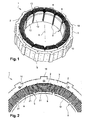
- the Figures 1, 2 , 3a and 3b show an X-axis stator 1 for a rotating electrical machine, such as an alternator, a motor or an alternator.
- This stator 1 comprises teeth 2 regularly distributed on the inner periphery of a yoke 3 and extending towards the inside of the stator 1.
- the stator 1 also comprises notches 5, two consecutive notches 5 being separated by a tooth 2 intended to to receive a coil 8.
- the yoke 3 consists of a strip of material connecting the teeth 2 between them extending between the bottom of the notches 5 and the outer periphery of the stator 1.
- the body of the stator 1 is made in the form of a stack of sheets of ferromagnetic material extending in a radial plane perpendicular to the axis X. In the radial plane, the plates of form The sheets are cut so as to delimit the contour of each tooth 2. The sheets are held by means of rivets 10 passing axially from one side to the stack of sheets for forming a stator 1 manipulated and transportable.
- two coils 8 are implanted in the same notch 5.
- Each coil 8 is wound around one of the teeth 2 delimiting the notch 5 by means of a coil insulator 9 visible on the Figures 3a, 3b and 5 and more specifically described below.
- the coils 8 are interconnected with each other, for example by welding or with the aid of a connector (not shown) to form a phase of the machine which may be of the polyphase type.
- the stator 1 is intended to be installed around a rotor so that the free ends of the teeth 2 delimit, in known manner, an air gap with the outer periphery of the rotor of the rotating electrical machine.
- the rotor may comprise a body made of laminated sheet which has housing. Permanent magnets are positioned inside at least some of these dwellings as visible for example in the Figures 1 and 2 of the document EP0803962 .
- the rotor of the machine may be a claw rotor as in the document FR2890798 , or with salient poles.
- the rotor with claws or salient poles may also include permanent magnets.
- each tooth 2 has lateral flanks 21 parallel to the axis X of the stator 1 which are inclined with respect to each other.
- the inclination of the flanks 21 is such that two sidewalls 21 facing each other corresponding to the edges delimiting a notch 5 are parallel to one another.
- the angle ⁇ between two lateral flanks 21 which intersect along a straight line located towards the inside of the stator 1 (cf. figure 3a ) is for example between 10 and 30 degrees.
- Each tooth 2 also has axial end faces 22 perpendicular to the X axis connected to each other by the lateral flanks 21. These faces 22 thus have a substantially trapezoidal view in plan view, the largest side of which is located on the side of the cylinder head 3.
- Each tooth 2 further comprises a tooth root 12 which extends on either side of the portion of the tooth 2 around which the coil 8 is wound.
- the portions of the tooth roots 12 of two adjacent teeth 2 turned one towards the other extend substantially parallel to the bottom of the corresponding notch 5.
- This notch configuration combined with the use of a wire 13 with a substantially rectangular section (flattened shape) to produce the coils 8 makes it possible to maximize the filling rate of the notches 5 by facilitating in particular the filling of the notches 5 at the level of the angles between the teeth 2 and the cylinder head 3 (cf. Figures 3a and 3b ).
- the wire 13 of rectangular shape has its largest side oriented perpendicularly to the lateral flanks 21 of the teeth 2.
- the wire 13 is wound on several turns around a tooth 2 in a compact manner so that each half-notch is filled by three layers C1, C2, C3 of six turns each or 18 turns per half-notch.
- Each notch 5 is thus filled by 36 turns in total.
- the son 13 consist of an electrically conductive wire, for example a copper wire and / or aluminum, coated with an electrical insulator, such as enamel.
- each notch 5 it will be possible to modify the number of turns contained in each notch 5 by varying the number of layers of turns and / or the number of turns in each layer of turn C1, C2, C3 or in some of them only, and the section of the wire 13. It will also be possible to change the orientation of the wire 13 of rectangular shape. So, in this embodiment of the figure 3b , the wire 13 has its largest side oriented parallel to the lateral flanks 21 of the teeth 2. In the example shown, there are 3 turns per layer C1, C2, C3, or 9 turns per half-notches and therefore 18 turns per notch 5.
- the stator 1 also comprises dovetail-shaped assembly means 16 extending from the outer periphery of the yoke for attachment with a housing (not shown) of the machine provided with bearings for mounting rotating the rotor shaft.
- the stator 1 is preferably with teeth 2 reported.
- Each tooth insert 2 comprises in this case two branches 17 corresponding to a circumferential portion of the yoke 3 which extend on either side of the portion of the tooth 2 carrying the coil 8.
- Complementary connecting means 18 are arranged on the end faces of the branches 17. These means 18 allow to connect the branches 17 of two adjacent teeth 2 in position in which the branches 17 of these two teeth 2 are in the extension of one another. It is thus possible to make the arms 17 work together in an annular manner so as to form a ring of teeth 2.
- each tooth 2 attached is inclined side-to-side with respect to the other, so that when the stator 1 is assembled, two adjacent teeth 2 delimit a notch 5 with parallel edges in pairs.
- the stator 1 thus formed will then be fixed to the housing by means of the assembly means 16 extending from an outer periphery of the branches 17 of each tooth 2.
- stator 1 can be made in one piece.
- the figure 5 shows a coil insulator 9 intended to be positioned around each tooth 2.
- This insulator 9 is an electrical insulator made here of electrically insulating material and moldable for example plastic such as PA 6.6.
- the insulator 9 has a body 91 formed by two parts 92 cut vertically, a single portion being shown in the figure. These parts are intended to be assembled for example by snapping around the tooth 2.
- the body 91 comprises a frame 93 positioned around a tooth 2.
- the body 91 further comprises a front edge 94 and a rear flange 95 defining with the walls of the frame 93 a mounting groove of the coil 8.
- the frame 93 substantially flat face may, however, include indentations at its periphery to facilitate the guiding of the wire 13 during the operation of winding.
- the rear flange 95 is intended to be positioned near the yoke 3 while the front flange 94 is located on the side of the tooth root 12.
- the two parts 92 can be cut vertically relative to each other according to a median plane or not of the insulation 9.
- the insulator 9 takes the form of a thin membrane, made of an electrically insulating material and heat conductor, for example an aramid material of Nomex type (trademark). This thin membrane is folded so that the insulator 9 is pressed against the faces of a notch 5 in order to isolate each coil 8 relative to the corresponding tooth 2.
- the stator 1 is formed by a plurality of teeth 2 reported. On the side of their free end, each tooth 2 comprises a tooth root 12.
- the stator 1 further comprises the support 3 of annular shape of axial orientation also made of laminated sheet corresponding to the yoke 3 of the stator 1.
- Assembly means 30 intervene between the support 3 and the teeth 2. These assembly means 30 are formed by a tenon 31 and a mortise 32 made in the inner wall of the support 3. Alternatively, the mortise 32 is made in the tooth 2, while the pin 31 belongs to the support 3. Alternatively, the assembly between the teeth 2 and the support 3 is made by press fitting, gluing, or welding.
- the number of teeth 2 of the stator 1 equal to 12 for the realization of the figure 1 or at 36 for carrying out the figure 6 and the section of the yoke 3 and teeth 2 may vary depending on the application to adapt the electrical performance of the machine.
- the teeth 2 may not be distributed circumferentially in a regular manner.
- the teeth 2 are devoid of a tooth root.
- the parts 92 are positioned on either side of the tooth 2 and assembled together by snapping.
- the insulator 9 thus formed is retained radially on the tooth by the tooth root 12.
- the wire 13 is wound compactly around the coil insulator 9 and easy and fast since this is performed outside the notches 5 in the case of teeth 2 reported.
- the winding is performed for example on three layers of windings C1, C2, C3 superimposed on each other.
- the preformed assembly comprising a coil insulation 9 and a coil 8 is then threaded around the tooth 2 concerned.
- an impregnation operation is then carried out on the winding of the stator 1 by an impregnating varnish.
- the stator 1 is heated as well as the varnish to be introduced in the liquid state drop by drop in the coils 8.
- the impregnation operation may be carried out by dipping partial and rolling stator assembled in a bath of impregnating varnish. This technique is particularly well suited to the invention in that the yoke 3 is reported relative to the housing.
- the impregnation operation can be carried out under vacuum or by completely simple dipping of the stator 1 in a bath of impregnating varnish.
- the varnish is cooled by polymerizing.
- the varnish is for example based on epoxy resin, unsaturated polyester resin or silicone resin.
- accelerators it is possible to add accelerators to the resins in order to reduce the duration of the impregnation.
- the rotating electrical machine may belong to a motor vehicle and be in the above manner an alternator, an alternator-starter which is a reversible alternator, an electric motor or an electromagnetic retarder.
- the rotor may be a rotor with permanent magnets with several magnets per housing subjected to the action of a spring as described in the application FR12 / 54733 filed on 24/20172012 .
Landscapes
- Engineering & Computer Science (AREA)
- Power Engineering (AREA)
- Insulation, Fastening Of Motor, Generator Windings (AREA)
- Iron Core Of Rotating Electric Machines (AREA)
Abstract
Description
- L'invention porte sur un stator bobiné pour machine électrique tournante ainsi que sur la machine électrique tournante correspondante.
- L'invention se rapporte au domaine des machines électriques tournantes telles que les moteurs, les alternateurs, ou les alterno-démarreurs.
- On connaît des machines électriques comportant un stator et un rotor solidaire d'un arbre. Le rotor pourra être solidaire d'un arbre menant et/ou mené et pourra appartenir à une machine électrique tournante sous la forme d'un alternateur comme décrit dans le document
EP0803962 ou d'un moteur électrique comme décrit dans le documentEP0831580 . - La machine électrique comporte un boîtier portant le stator. Ce boîtier est configuré pour porter à rotation l'arbre par exemple par l'intermédiaire de roulements, tels que des roulements à billes et/ou à aiguilles. Le rotor pourra comporter un corps réalisé en tôle feuilletée, qui comporte des logements. Des aimants permanents sont positionnés à l'intérieur d'au moins certains de ces logements comme visible par exemple dans les
figures 1 et 2 du documentEP0803962 . - Comme décrit dans le document
FR2890798 - Afin de réaliser un bobinage dit "concentrique", on monte sur les dents du stator des bobines réalisées à partir d'un fil enroulé sur plusieurs tours. Les fils consistent par exemple en un fil de cuivre revêtu d'émail. Deux bobines sont implantées dans une même encoche, chaque bobine étant enroulée autour de l'une des dents délimitant l'encoche par l'intermédiaire d'un isolant de bobine. Les bobines sont interconnectées entre elles, par exemple par soudure ou à l'aide d'un connecteur pour former une phase de la machine qui pourra être du type polyphasée.
- Le document japonais
JP2004350450 - L'invention vise à maximiser le taux de remplissage des encoches du stator afin d'améliorer les performances de la machine.
- A cet effet, l'invention a pour objet un stator bobiné de machine électrique tournante comportant une culasse, des dents réparties sur une périphérie interne de ladite culasse s'étendant vers l'intérieur dudit stator et délimitant deux à deux des encoches, ainsi que des bobines formées autour de chaque dent à partir d'un fil ayant une section de forme sensiblement rectangulaire, caractérisé en ce que les flancs latéraux d'une même dent sont inclinés l'un par rapport à l'autre, en sorte que deux flancs latéraux de deux dents adjacentes tournés l'un vers l'autre correspondant aux bords délimitant une encoche sont parallèles entre eux.
- Ainsi, l'utilisation en combinaison d'encoches à bords parallèles et d'un fil de section rectangulaire permet de maximiser le taux de remplissage de l'encoche en permettant notamment de combler de manière aisée les espaces au niveau des angles de l'encoche. Grâce à l'invention, il sera ainsi possible d'obtenir des taux de remplissage supérieurs à 50% pouvant atteindre 60% dans certaines applications.
- Selon une réalisation, le stator comporte en outre un isolant de bobine monté autour de chaque dent.
- Selon une réalisation, le fil de bobine de forme rectangulaire présente son plus grand côté orienté parallèlement aux flancs latéraux des dents délimitant l'encoche dans laquelle est positionné ledit fil de bobine.
- Selon une réalisation, le fil de bobine de forme rectangulaire présente son plus grand côté orienté perpendiculairement aux flancs latéraux des dents délimitant l'encoche dans laquelle est positionné ledit fil de bobine.
- Selon une réalisation, le fil de bobine présente une section carrée.
- Selon une réalisation, le stator comporte des dents rapportées.
- Selon une réalisation, l'enroulement du fil de bobine autour d'une dent rapportée est réalisé avant assemblage des dents rapportées pour former le stator.
- Ainsi, on peut enrouler le fil autour d'une dent facilement sans être gêner. Cela est d'autant plus intéressant qu'étant donné la forme de la dent à flancs non parallèles (qui permettent d'obtenir l'encoche à bords parallèles) il faut effectuer une torsion du fil lorsqu'on passe d'un flanc à un autre.
- Selon une réalisation, chaque dent rapportée comporte deux branches correspondant à une portion de la culasse, lesdites branches de deux dents adjacentes étant aptes à coopérer entre elles pour former ledit stator.
- Selon une réalisation, les dents rapportées comportent des moyens de fixation sur une paroi annulaire formant ladite culasse du stator.
- Selon une réalisation, chaque dent comporte un pied de dent.
- Selon une réalisation, chaque pied de dent s'étend parallèlement au fond de l'encoche correspondante.
- Selon une réalisation, l'isolant de bobine est réalisé en deux parties.
- Selon une réalisation, les deux parties de l'isolant de bobine sont découpées suivant un plan horizontal perpendiculaire à un axe dudit stator.
- Selon une réalisation, le stator comporte des fentes situées de part et d'autre de chaque dent aptes à recevoir des saillies dudit isolant de bobine.
- Selon une réalisation, le stator comporte en outre des moyens d'assemblage pour la fixation avec un boîtier de machine électrique tournante.
- L'invention a également pour objet une machine électrique tournante munie d'un stator bobiné selon l'invention.
- L'invention sera mieux comprise à la lecture de la description qui suit et à l'examen des figures qui l'accompagnent. Ces figures ne sont données qu'à titre illustratif mais nullement limitatif de l'invention.
- La
figure 1 montre une vue en perspective d'un stator bobiné conforme à l'invention; - La
figure 2 est une vue de dessus du stator bobiné de lafigure 1 ; - La
figure 3a représente une vue en coupe transversale suivant une plan perpendiculaire à l'axe X du stator bobiné de lafigure 1 ; - La
figure 3b montre une vue en coupe d'un stator bobiné selon l'invention comportant des bobines formée partir d'un fil en forme de méplat ayant une orientation différente par rapport à celle de lafigure 3a ; - La
figure 4 montre une vue de dessus d'une dent rapportée du stator selon l'invention; - La
figure 5 est une vue en perspective d'un isolant de bobine réalisé en deux parties utilisé avec la dent rapportée de lafigure 4 ; - La
figure 6 est une vue en perspective d'un autre mode de réalisation du stator à dents rapportées. - Les éléments identiques, similaires, ou analogues conservent la même référence d'une figure à l'autre.
- Les
figures 1, 2 ,3a et 3b montrent un stator 1 d'axe X pour machine électrique tournante, telle qu'un alternateur, un moteur ou un alternodémarreur. Ce stator 1 comporte des dents 2 réparties régulièrement sur la périphérie interne d'une culasse 3 et s'étendant vers l'intérieur du stator 1. Le stator 1 comporte également des encoches 5, deux encoches 5 consécutives étant séparées par une dent 2 destinée à recevoir une bobine 8. La culasse 3 consiste en une bande de matière reliant les dents 2 entre elles s'étendant entre le fond des encoches 5 et la périphérie externe du stator 1. - Afin de diminuer les courants de Foucault, le corps du stator 1 est réalisé sous la forme d'un empilement de tôles en matière ferromagnétique s'étendant dans un plan radial perpendiculaire à l'axe X. Dans le plan radial, les tôles de forme annulaire sont découpées de manière à délimiter le contour de chaque dent 2. Les tôles sont maintenues au moyen de rivets 10 traversant axialement de part en part l'empilement de tôles pour formation d'un stator 1 manipulable et transportable.
- Dans une forme de réalisation, deux bobines 8 sont implantées dans une même encoche 5. Chaque bobine 8 est enroulée autour de l'une des dents 2 délimitant l'encoche 5 par l'intermédiaire d'un isolant de bobine 9 visible sur les
figures 3a, 3b et5 et décrit plus précisément ci-après. Les bobines 8 sont interconnectées entre elles, par exemple par soudure ou à l'aide d'un connecteur (non représenté) pour former une phase de la machine qui pourra être du type polyphasé. - Le stator 1 est destiné à être installé autour d'un rotor de sorte que les extrémités libres des dents 2 délimitent, de manière connue, un entrefer avec la périphérie externe du rotor de la machine électrique tournante. Le rotor pourra comporter un corps réalisé en tôle feuilletée qui présente des logements. Des aimants permanents sont positionnés à l'intérieur d'au moins certains de ces logements comme visible par exemple dans les
figures 1 et 2 du documentEP0803962 . En variante, le rotor de la machine pourra être un rotor à griffes comme dans le documentFR2890798 - Plus précisément, comme cela est bien visible sur les
figures 3a, 3b et4 , chaque dent 2 présente des flancs latéraux 21 parallèles à l'axe X du stator 1 qui sont inclinés l'un par rapport à l'autre. L'inclinaison des flancs 21 est telle que deux flancs 21 en vis-à-vis correspondant aux bords délimitant une encoche 5 sont parallèles l'un par rapport à l'autre. L'angle α entre deux flancs latéraux 21 qui se coupent suivant une droite située vers l'intérieur du stator 1 (cf.figure 3a ) est par exemple compris entre 10 et 30 degrés. Chaque dent 2 comporte également des faces 22 d'extrémité axiales perpendiculaires à l'axe X reliées entre elles par les flancs latéraux 21. Ces faces 22 présentent ainsi en vue de dessus sensiblement la forme d'un trapèze dont le plus grand côté est situé du côté de la culasse 3. - Chaque dent 2 comporte en outre un pied de dent 12 qui s'étend de part et d'autre de la partie de la dent 2 autour de laquelle est enroulée la bobine 8. Les parties des pieds de dent 12 de deux dents 2 adjacentes tournées l'une vers l'autre s'étendent sensiblement parallèlement au fond de l'encoche 5 correspondante. Cette configuration d'encoche combinée à l'utilisation d'un fil 13 à section sensiblement rectangulaire (forme en méplat) pour réaliser les bobines 8 permet de maximiser le taux de remplissage des encoches 5 en facilitant notamment le remplissage des encoches 5 au niveau des angles entre les dents 2 et la culasse 3 (cf.
figures 3a et 3b ). - Dans le mode de réalisation de la
figure 3a , le fil 13 de forme rectangulaire présente son plus grand côté orienté perpendiculairement aux flancs latéraux 21 des dents 2. Le fil 13 est enroulé sur plusieurs tours autour d'une dent 2 de manière compacte en sorte que chaque demi-encoche est remplie par trois couches C1, C2, C3 de six spires chacune soit 18 spires par demi-encoche. Chaque encoche 5 est ainsi remplie par 36 spires au total. Les fils 13 consistent en un fil électriquement conducteur, par exemple en un fil de cuivre et/ou en aluminium, revêtu d'un isolant électrique, tel que de l'émail. - Bien entendu, afin d'adapter les performances de la machine en fonction de l'application, il sera possible de modifier le nombre de spires contenues dans chaque encoche 5 en faisant varier le nombre de couches de spires et/ou le nombre de spires dans chaque couche de spire C1, C2, C3 ou dans certaines d'entre elles uniquement, ainsi que la section du fil 13. Il sera également possible de modifier l'orientation du fil 13 de forme rectangulaire. Ainsi, dans ce mode de réalisation de la
figure 3b , le fil 13 présente son plus grand côté orienté parallèlement aux flancs latéraux 21 des dents 2. Dans l'exemple représenté, on a 3 spires par couche C1, C2, C3, soit 9 spires par demi-encoches et donc 18 spires par encoche 5. - Il serait possible que différentes portions d'une même bobine soient formées à partir du fil 13 ayant une orientation qui varie suivant la portion de bobine considérée. Autrement dit, l'orientation du fil en forme de méplat 13 pourra être différente d'une portion de bobine à une autre.
- De préférence, le stator 1 comporte également des moyens d'assemblage 16 en forme de queue d'aronde s'étendant depuis la périphérie externe de la culasse pour la fixation avec un boîtier (non représenté) de la machine muni de paliers pour le montage à rotation de l'arbre de rotor.
- Comme montré sur la
figure 4 , le stator 1 est de préférence à dents 2 rapportées. Chaque dent rapportée 2 comporte en l'occurrence deux branches 17 correspondant à une portion circonférentielle de la culasse 3 qui s'étendent de part et d'autre de la portion de la dent 2 portant la bobine 8. Des moyens complémentaires de liaison 18 sont disposés sur les faces extrémités des branches 17. Ces moyens 18 permettent de raccorder les branches 17 de deux dents 2 adjacentes en position dans laquelle les branches 17 de ces deux dents 2 se trouvent dans le prolongement l'une de l'autre. Il est ainsi possible de faire coopérer les branches 17 entre elles de manière annulaire pour former une couronne de dents 2. Comme indiqué précédemment, chaque dent 2 rapportée est à flancs latéraux 21 inclinés l'un par rapport à l'autre, en sorte que lorsque le stator 1 est assemblé, deux dents 2 adjacentes délimitent une encoche 5 à bords parallèles deux à deux. Le stator 1 ainsi formé sera ensuite fixé au boîtier à l'aide des moyens d'assemblage 16 s'étendant depuis une périphérie externe des branches 17 de chaque dent 2. - En outre, deux fentes 19 sont ménagées de part et d'autre de la dent 2. Ces fentes 19 sont situées au niveau de la jonction entre la portion de la dent 2 portant la bobine 8 et les branches 17 pour permettre la pénétration de saillies appartenant à l'isolant de bobine 9. Une telle configuration permet d'assurer un bon maintien en position de l'isolant de bobine 9 lors d'une opération de soudage des extrémités des fils 13 des bobines 8 sur des bornes d'un connecteur. En variante, le stator 1 pourra être réalisé d'un seul tenant.
- La
figure 5 montre un isolant de bobine 9 destiné à être positionné autour de chaque dent 2. Cet isolant 9 est un isolant électrique réalisé ici en matière électriquement isolante et moulable par exemple en matière plastique telle que du PA 6.6. L'isolant 9 présente un corps 91 formé par deux parties 92 découpées verticalement, une seule partie étant représentée sur la figure. Ces parties sont destinées à être assemblées par exemple par encliquetage autour de la dent 2. Lorsque les parties 92 sont assemblées entre elles, le corps 91 comporte un cadre 93 positionné autour d'une dent 2. Le corps 91 comporte en outre un rebord avant 94 et un rebord arrière 95 définissant avec les parois du cadre 93 une gorge de montage de la bobine 8. Le cadre 93 à face sensiblement plane pourra toutefois comporter des empreintes à sa périphérie pour faciliter le guidage du fil 13 lors de l'opération de bobinage. Le rebord arrière 95 est destiné à être positionné à proximité de la culasse 3 tandis que le rebord avant 94 est situé du côté du pied de dent 12. Alternativement, les deux parties 92 pourront être découpées verticalement l'une par rapport à l'autre suivant un plan médian ou non de l'isolant 9. - En variante, l'isolant 9 prend la forme d'une membrane fine, réalisée dans un matériau électriquement isolant et conducteur de chaleur, par exemple un matériau aramide de type dit Nomex (marque déposée). Cette membrane fine est pliée de manière que l'isolant 9 est plaqué contre les faces d'une encoche 5 afin d'isoler chaque bobine 8 par rapport à la dent 2 correspondante.
- Dans un autre mode de réalisation montré à la
figure 6 , le stator 1 est formé par une pluralité de dents 2 rapportées. Du côté de leur extrémité libre, chaque dent 2 comporte un pied de dent 12. Le stator 1 comporte en outre le support 3 de forme annulaire d'orientation axiale réalisé également en tôle feuilletée correspondant à la culasse 3 du stator 1. Des moyens d'assemblage 30 interviennent entre le support 3 et les dents 2. Ces moyens d'assemblage 30 sont formés par un tenon 31 et une mortaise 32 réalisée dans la paroi interne du support 3. En variante, la mortaise 32 est réalisée dans la dent 2, tandis que le tenon 31 appartient au support 3. En variante, l'assemblage entre les dents 2 et le support 3 est effectué par emmanchement à force, collage, ou soudage. - Bien entendu, le nombre de dents 2 du stator 1 égal à 12 pour la réalisation de la
figure 1 ou à 36 pour la réalisation de lafigure 6 ainsi que la section de la culasse 3 et des dents 2 pourront varier en fonction de l'application afin d'adapter les performances électriques de la machine. En variante, les dents 2 pourront ne pas être réparties circonférentiellement de manière régulière. En variante, les dents 2 sont dépourvues de pied de dent. - On décrit ci-après une opération de bobinage du stator 1 selon l'invention.
- On installe dans un premier temps les isolants de bobine 9 autour des dents 2 du stator 1. A cet effet, les parties 92 sont positionnées de part et d'autre de la dent 2 et assemblées entre elles par encliquetage. L'isolant 9 ainsi formé est retenu radialement sur la dent par le pied de dent 12.
- Le fil 13 est enroulé de manière compacte autour de l'isolant de bobine 9 et ce de manière aisée et rapide puisque cela est réalisé en dehors des encoches 5 dans le cas de dents 2 rapportées. Le bobinage est effectué par exemple sur trois couches d'enroulements C1, C2, C3 superposées les unes sur les autres. En variante, dans le cas où le stator 1 est dépourvu de pied de dent 12, il sera possible de réaliser le bobinage indépendamment des dents 2 du stator 1 en réalisant les bobines 8 autour de l'isolant de bobine 9 monté sur un support 3. L'ensemble préformé comportant un isolant de bobine 9 et une bobine 8 est ensuite enfilé autour de la dent 2 concernée.
- On effectue ensuite une opération d'imprégnation du bobinage du stator 1 par un vernis d'imprégnation. A cette fin, le stator 1 est chauffé ainsi que le vernis pour être introduit à l'état liquide goutte à goutte dans les bobines 8. En variante, l'opération d'imprégnation pourra être réalisée par trempage partiel et roulage du stator assemblé dans un bain de vernis d'imprégnation. Cette technique est particulièrement bien adaptée à l'invention dans la mesure où la culasse 3 est rapportée par rapport au boîtier. En variante, l'opération d'imprégnation pourra être réalisée sous vide ou par trempage simple complet du stator 1 dans un bain de vernis d'imprégnation.
- Ensuite, le vernis est refroidi en se polymérisant. Le vernis est par exemple à base de résine époxy, de résine polyester non saturée ou de résine silicone. Bien entendu, de manière connue, on peut ajouter aux résines des accélérateurs pour diminuer la durée de l'imprégnation.
- La machine électrique tournante pourra appartenir à un véhicule automobile et être de manière précitée un alternateur, un alterno-démarreur qui est un alternateur réversible, un moteur électrique ou un ralentisseur électromagnétique.
- Dans le cadre d'un alternateur appartenant à un prolongateur d'autonomie d'un véhicule électrique (Range-extender en Anglais), le rotor pourra être un rotor à aimants permanents avec plusieurs aimants par logement soumis à l'action d'un ressort comme décrit dans la demande
FR12/54733 déposée le 24/05/2012
Claims (15)
- Stator bobiné (1) de machine électrique tournante comportant une culasse (3), des dents (2) réparties sur une périphérie interne de ladite culasse (3) s'étendant vers l'intérieur dudit stator (1) et délimitant deux à deux des encoches (5), ainsi que des bobines (8) formées autour de chaque dent (2) à partir d'un fil (13) ayant une section de forme sensiblement rectangulaire, caractérisé en ce que des flancs latéraux (21) d'une même dent (2) sont inclinés l'un par rapport à l'autre, en sorte que deux flancs latéraux (21) de deux dents (2) adjacentes tournés l'un vers l'autre correspondant aux bords délimitant une encoche sont parallèles entre eux et en ce que le fil de bobine (13) de forme rectangulaire présente son plus grand côté orienté perpendiculairement aux flancs latéraux (21) des dents (2) délimitant l'encoche (5) dans laquelle est positionné ledit fil de bobine.
- Stator selon l'une des revendications 1, caractérisé en ce qu'il comporte en outre un isolant de bobine (9) monté autour de chaque dent (2).
- Stator selon la revendication 1 ou 2, caractérisé en ce que le fil de bobine (13) de forme rectangulaire présente son plus grand côté orienté parallèlement aux flancs latéraux (21) des dents (2) délimitant l'encoche (5) dans laquelle est positionné ledit fil de bobine.
- Stator selon l'une des revendications 1 à 3, caractérisé en ce que le fil de bobine (13) présente une section carrée.
- Stator selon l'une des revendications 1 à 4, caractérisé en ce qu'il comporte des dents (2) rapportées.
- Stator selon la revendication 5, caractérisé en ce que l'enroulement du fil de bobine autour d'une dent rapportée est réalisé avant assemblage des dents rapportées pour former le stator.
- Stator selon la revendication 6, caractérisé en ce que chaque dent rapportée (2) comporte deux branches (17) correspondant à une portion de la culasse (3), lesdites branches (17) de deux dents (2) adjacentes étant aptes à coopérer entre elles pour former ledit stator (1).
- Stator selon la revendication 6, caractérisé en ce que les dents (2) rapportées comportent des moyens de fixation (30) sur une paroi annulaire formant ladite culasse (3) du stator (1).
- Stator selon l'une des revendications 1 à 8, caractérisé en ce que chaque dent (2) comporte un pied de dent (12).
- Stator selon la revendication 9, caractérisé en ce que chaque pied de dent (12) s'étend parallèlement au fond de l'encoche (5) correspondante.
- Stator selon les revendications 2 et 10, caractérisé en ce que l'isolant de bobine (9) est réalisé en deux parties (92).
- Stator selon la revendication 11, caractérisé en ce que les deux parties (92) de l'isolant de bobine (9) sont découpées suivant un plan horizontal perpendiculaire à un axe dudit stator (1).
- Stator selon la revendication 2 ou l'une des revendications 3 à 12 quand dépendantes de la revendication 2, caractérisé en ce qu'il comporte des fentes (19) situées de part et d'autre de chaque dent (2) aptes à recevoir des saillies dudit isolant de bobine (9).
- Stator selon l'une des revendications 1 à 13, caractérisé en ce qu'il comporte en outre des moyens d'assemblage (16) pour la fixation avec un boîtier de machine électrique tournante.
- Machine électrique tournante munie d'un stator bobiné (1) selon l'une des revendications précédentes.
Applications Claiming Priority (1)
| Application Number | Priority Date | Filing Date | Title |
|---|---|---|---|
| FR1357216A FR3009141B1 (fr) | 2013-07-23 | 2013-07-23 | Stator bobine a remplissage d'encoches optimise et machine electrique correspondante |
Publications (2)
| Publication Number | Publication Date |
|---|---|
| EP2860847A1 true EP2860847A1 (fr) | 2015-04-15 |
| EP2860847B1 EP2860847B1 (fr) | 2022-06-08 |
Family
ID=49713174
Family Applications (1)
| Application Number | Title | Priority Date | Filing Date |
|---|---|---|---|
| EP14177886.0A Active EP2860847B1 (fr) | 2013-07-23 | 2014-07-21 | Stator bobiné à remplissage d'encoches optimisé et machine électrique correspondante |
Country Status (2)
| Country | Link |
|---|---|
| EP (1) | EP2860847B1 (fr) |
| FR (1) | FR3009141B1 (fr) |
Cited By (2)
| Publication number | Priority date | Publication date | Assignee | Title |
|---|---|---|---|---|
| EP3748816A1 (fr) * | 2019-06-03 | 2020-12-09 | Hamilton Sundstrand Corporation | Machines électriques |
| FR3128330A1 (fr) | 2021-10-20 | 2023-04-21 | Francois Bernot | Armature magnétique à dents amovibles |
Families Citing this family (2)
| Publication number | Priority date | Publication date | Assignee | Title |
|---|---|---|---|---|
| FR3041184A1 (fr) * | 2015-09-11 | 2017-03-17 | Valeo Equip Electr Moteur | Stator de machine electrique tournante muni de toles fixees par rivetage ou bouterollage |
| CN110858732B (zh) * | 2018-08-24 | 2022-04-19 | 广东威灵电机制造有限公司 | 定子和电机 |
Citations (10)
| Publication number | Priority date | Publication date | Assignee | Title |
|---|---|---|---|---|
| FR1254733A (fr) | 1960-04-21 | 1961-02-24 | Williamson Inc T | Indicateur de passage de racles à l'intérieur d'une conduite |
| EP0803962A1 (fr) | 1996-04-23 | 1997-10-29 | Bamo Elettroutensili S.r.l. | Paquet de tÔles de rotor pour rotors à aimants permanents pour alternateurs ou similaires |
| EP0831580A2 (fr) | 1996-09-21 | 1998-03-25 | AKO-Werke GmbH & Co. KG | Dispositif de commande d'entraínement à courant pour moteurs commutés à aimant permanent |
| US20040124733A1 (en) * | 2002-12-25 | 2004-07-01 | Noriaki Yamamoto | Rotating electric machine, motor-driven vehicle and resin insert-molding method |
| JP2004350450A (ja) | 2003-05-23 | 2004-12-09 | Honda Motor Co Ltd | ステータ |
| EP1602554A2 (fr) * | 2004-06-03 | 2005-12-07 | Hitachi, Ltd. | Moteur à courant continu sans balai pour direction assistée électrique et procedé de production de celui-ci |
| FR2890798A1 (fr) | 2005-09-13 | 2007-03-16 | Valeo Equip Electr Moteur | Stator de machine electrique tournante polyphasee du type alternateur ou alterno-demarreur |
| EP1806822A1 (fr) * | 2004-10-29 | 2007-07-11 | Toyota Jidosha Kabushiki Kaisha | Moteur-générateur et automobile équipée de celui-ci |
| JP2007221913A (ja) * | 2006-02-16 | 2007-08-30 | Sawafuji Electric Co Ltd | 回転電機用電機子 |
| US20090085422A1 (en) * | 2005-11-11 | 2009-04-02 | Sumitomo Electric Industries, Ltd. | Motor Core Component and Motor Component |
Family Cites Families (1)
| Publication number | Priority date | Publication date | Assignee | Title |
|---|---|---|---|---|
| JP4998450B2 (ja) * | 2008-12-09 | 2012-08-15 | トヨタ自動車株式会社 | ステータの製造方法 |
-
2013
- 2013-07-23 FR FR1357216A patent/FR3009141B1/fr active Active
-
2014
- 2014-07-21 EP EP14177886.0A patent/EP2860847B1/fr active Active
Patent Citations (10)
| Publication number | Priority date | Publication date | Assignee | Title |
|---|---|---|---|---|
| FR1254733A (fr) | 1960-04-21 | 1961-02-24 | Williamson Inc T | Indicateur de passage de racles à l'intérieur d'une conduite |
| EP0803962A1 (fr) | 1996-04-23 | 1997-10-29 | Bamo Elettroutensili S.r.l. | Paquet de tÔles de rotor pour rotors à aimants permanents pour alternateurs ou similaires |
| EP0831580A2 (fr) | 1996-09-21 | 1998-03-25 | AKO-Werke GmbH & Co. KG | Dispositif de commande d'entraínement à courant pour moteurs commutés à aimant permanent |
| US20040124733A1 (en) * | 2002-12-25 | 2004-07-01 | Noriaki Yamamoto | Rotating electric machine, motor-driven vehicle and resin insert-molding method |
| JP2004350450A (ja) | 2003-05-23 | 2004-12-09 | Honda Motor Co Ltd | ステータ |
| EP1602554A2 (fr) * | 2004-06-03 | 2005-12-07 | Hitachi, Ltd. | Moteur à courant continu sans balai pour direction assistée électrique et procedé de production de celui-ci |
| EP1806822A1 (fr) * | 2004-10-29 | 2007-07-11 | Toyota Jidosha Kabushiki Kaisha | Moteur-générateur et automobile équipée de celui-ci |
| FR2890798A1 (fr) | 2005-09-13 | 2007-03-16 | Valeo Equip Electr Moteur | Stator de machine electrique tournante polyphasee du type alternateur ou alterno-demarreur |
| US20090085422A1 (en) * | 2005-11-11 | 2009-04-02 | Sumitomo Electric Industries, Ltd. | Motor Core Component and Motor Component |
| JP2007221913A (ja) * | 2006-02-16 | 2007-08-30 | Sawafuji Electric Co Ltd | 回転電機用電機子 |
Cited By (3)
| Publication number | Priority date | Publication date | Assignee | Title |
|---|---|---|---|---|
| EP3748816A1 (fr) * | 2019-06-03 | 2020-12-09 | Hamilton Sundstrand Corporation | Machines électriques |
| US11496008B2 (en) | 2019-06-03 | 2022-11-08 | Hamilton Sundstrand Corporation | Electrical machines |
| FR3128330A1 (fr) | 2021-10-20 | 2023-04-21 | Francois Bernot | Armature magnétique à dents amovibles |
Also Published As
| Publication number | Publication date |
|---|---|
| EP2860847B1 (fr) | 2022-06-08 |
| FR3009141A1 (fr) | 2015-01-30 |
| FR3009141B1 (fr) | 2016-10-21 |
Similar Documents
| Publication | Publication Date | Title |
|---|---|---|
| EP2677633B1 (fr) | Isolant de bobine composé et élément de machine électrique associé | |
| EP2677634B1 (fr) | Interconnecteur pour un stator d'une machine électrique et stator comprenant un tel interconnecteur | |
| EP3005534B1 (fr) | Machine electrique munie d'un amortisseur pour resister mecaniquement aux sollicitations vibratoires et amortisseur correspondant | |
| EP2826133B1 (fr) | Ensemble de flasques comportant des pales axiales generant un flux d'air axial a travers d'un rotor | |
| EP2860847B1 (fr) | Stator bobiné à remplissage d'encoches optimisé et machine électrique correspondante | |
| EP2795765B1 (fr) | Rotor a poles saillants comportant un dispositif d'isolation de bobinages et dispositif d'isolation de bobinages associe | |
| EP2896117B1 (fr) | Isolant de bobine mixte réalisé en deux parties et élément de machine électrique correspondant | |
| WO2014041313A1 (fr) | Stator a dents rapportees pour machine electrique tournante et machine electrique tournante correspondante | |
| EP2983272B1 (fr) | Induit de machine électrique tournante à performances magnétiques améliorées | |
| FR2995470A1 (fr) | Isolant de bobine realise en deux parties et element de machine electrique correspondant | |
| FR3023994A1 (fr) | Procede de realisation d'un stator bobine de machine electrique tournante | |
| EP2846438B1 (fr) | Isolant de bobine | |
| FR2995472A1 (fr) | Interconnecteur pour stator de machine electrique, cache isolant, et stator de machine electrique correspondants | |
| EP2608363A1 (fr) | Flasques de maintien des chignons de bobinages et rotor à pôles saillants comportant lesdites flasques | |
| WO2018020188A1 (fr) | Machine electrique tournante munie d'un stator avec un bobinage epingle | |
| WO2017042487A9 (fr) | Stator de machine electrique muni d'un isolant d'encoche surmoule | |
| FR3054743B1 (fr) | Bobine pour machine electrique tournante | |
| FR3046707B1 (fr) | Isolant de bobine perfectionne et machine electrique tournante comportant un tel isolant | |
| FR2995738A1 (fr) | Stator pour machine electrique tournante muni d'un circuit de refroidissement et machine electrique tournante correspondante | |
| FR2984630A1 (fr) | Rotor a poles saillants comportant des flasques de maintien des chignons de bobinages et flasques de maintien associes | |
| WO2017093640A1 (fr) | Rotor a griffes de machine electrique tournante muni d'au moins un chanfrein realise dans une griffe | |
| FR3073339A1 (fr) | Machine electrique tournante munie de moyens de blocage de papier isolant d'encoche | |
| WO2017093634A1 (fr) | Rotor a griffes de machine electrique tournante a performances magnetiques ameliorees | |
| WO2018002522A1 (fr) | Rotor a double excitation pour machine electrique tournante | |
| FR3062968A1 (fr) | Rotor de machine electrique tournante muni d'un support d'elements magnetiques |
Legal Events
| Date | Code | Title | Description |
|---|---|---|---|
| PUAI | Public reference made under article 153(3) epc to a published international application that has entered the european phase |
Free format text: ORIGINAL CODE: 0009012 |
|
| 17P | Request for examination filed |
Effective date: 20140723 |
|
| AK | Designated contracting states |
Kind code of ref document: A1 Designated state(s): AL AT BE BG CH CY CZ DE DK EE ES FI FR GB GR HR HU IE IS IT LI LT LU LV MC MK MT NL NO PL PT RO RS SE SI SK SM TR |
|
| AX | Request for extension of the european patent |
Extension state: BA ME |
|
| STAA | Information on the status of an ep patent application or granted ep patent |
Free format text: STATUS: EXAMINATION IS IN PROGRESS |
|
| 17Q | First examination report despatched |
Effective date: 20200525 |
|
| STAA | Information on the status of an ep patent application or granted ep patent |
Free format text: STATUS: EXAMINATION IS IN PROGRESS |
|
| STAA | Information on the status of an ep patent application or granted ep patent |
Free format text: STATUS: EXAMINATION IS IN PROGRESS |
|
| GRAP | Despatch of communication of intention to grant a patent |
Free format text: ORIGINAL CODE: EPIDOSNIGR1 |
|
| STAA | Information on the status of an ep patent application or granted ep patent |
Free format text: STATUS: GRANT OF PATENT IS INTENDED |
|
| INTG | Intention to grant announced |
Effective date: 20220124 |
|
| GRAS | Grant fee paid |
Free format text: ORIGINAL CODE: EPIDOSNIGR3 |
|
| GRAA | (expected) grant |
Free format text: ORIGINAL CODE: 0009210 |
|
| STAA | Information on the status of an ep patent application or granted ep patent |
Free format text: STATUS: THE PATENT HAS BEEN GRANTED |
|
| AK | Designated contracting states |
Kind code of ref document: B1 Designated state(s): AL AT BE BG CH CY CZ DE DK EE ES FI FR GB GR HR HU IE IS IT LI LT LU LV MC MK MT NL NO PL PT RO RS SE SI SK SM TR |
|
| REG | Reference to a national code |
Ref country code: GB Ref legal event code: FG4D Free format text: NOT ENGLISH |
|
| REG | Reference to a national code |
Ref country code: AT Ref legal event code: REF Ref document number: 1497600 Country of ref document: AT Kind code of ref document: T Effective date: 20220615 Ref country code: CH Ref legal event code: EP |
|
| REG | Reference to a national code |
Ref country code: DE Ref legal event code: R096 Ref document number: 602014083949 Country of ref document: DE |
|
| REG | Reference to a national code |
Ref country code: IE Ref legal event code: FG4D Free format text: LANGUAGE OF EP DOCUMENT: FRENCH |
|
| REG | Reference to a national code |
Ref country code: LT Ref legal event code: MG9D |
|
| REG | Reference to a national code |
Ref country code: NL Ref legal event code: MP Effective date: 20220608 |
|
| PG25 | Lapsed in a contracting state [announced via postgrant information from national office to epo] |
Ref country code: SE Free format text: LAPSE BECAUSE OF FAILURE TO SUBMIT A TRANSLATION OF THE DESCRIPTION OR TO PAY THE FEE WITHIN THE PRESCRIBED TIME-LIMIT Effective date: 20220608 Ref country code: NO Free format text: LAPSE BECAUSE OF FAILURE TO SUBMIT A TRANSLATION OF THE DESCRIPTION OR TO PAY THE FEE WITHIN THE PRESCRIBED TIME-LIMIT Effective date: 20220908 Ref country code: LT Free format text: LAPSE BECAUSE OF FAILURE TO SUBMIT A TRANSLATION OF THE DESCRIPTION OR TO PAY THE FEE WITHIN THE PRESCRIBED TIME-LIMIT Effective date: 20220608 Ref country code: HR Free format text: LAPSE BECAUSE OF FAILURE TO SUBMIT A TRANSLATION OF THE DESCRIPTION OR TO PAY THE FEE WITHIN THE PRESCRIBED TIME-LIMIT Effective date: 20220608 Ref country code: GR Free format text: LAPSE BECAUSE OF FAILURE TO SUBMIT A TRANSLATION OF THE DESCRIPTION OR TO PAY THE FEE WITHIN THE PRESCRIBED TIME-LIMIT Effective date: 20220909 Ref country code: FI Free format text: LAPSE BECAUSE OF FAILURE TO SUBMIT A TRANSLATION OF THE DESCRIPTION OR TO PAY THE FEE WITHIN THE PRESCRIBED TIME-LIMIT Effective date: 20220608 Ref country code: ES Free format text: LAPSE BECAUSE OF FAILURE TO SUBMIT A TRANSLATION OF THE DESCRIPTION OR TO PAY THE FEE WITHIN THE PRESCRIBED TIME-LIMIT Effective date: 20220608 Ref country code: BG Free format text: LAPSE BECAUSE OF FAILURE TO SUBMIT A TRANSLATION OF THE DESCRIPTION OR TO PAY THE FEE WITHIN THE PRESCRIBED TIME-LIMIT Effective date: 20220908 |
|
| REG | Reference to a national code |
Ref country code: AT Ref legal event code: MK05 Ref document number: 1497600 Country of ref document: AT Kind code of ref document: T Effective date: 20220608 |
|
| PG25 | Lapsed in a contracting state [announced via postgrant information from national office to epo] |
Ref country code: RS Free format text: LAPSE BECAUSE OF FAILURE TO SUBMIT A TRANSLATION OF THE DESCRIPTION OR TO PAY THE FEE WITHIN THE PRESCRIBED TIME-LIMIT Effective date: 20220608 Ref country code: LV Free format text: LAPSE BECAUSE OF FAILURE TO SUBMIT A TRANSLATION OF THE DESCRIPTION OR TO PAY THE FEE WITHIN THE PRESCRIBED TIME-LIMIT Effective date: 20220608 |
|
| PG25 | Lapsed in a contracting state [announced via postgrant information from national office to epo] |
Ref country code: NL Free format text: LAPSE BECAUSE OF FAILURE TO SUBMIT A TRANSLATION OF THE DESCRIPTION OR TO PAY THE FEE WITHIN THE PRESCRIBED TIME-LIMIT Effective date: 20220608 |
|
| PG25 | Lapsed in a contracting state [announced via postgrant information from national office to epo] |
Ref country code: SM Free format text: LAPSE BECAUSE OF FAILURE TO SUBMIT A TRANSLATION OF THE DESCRIPTION OR TO PAY THE FEE WITHIN THE PRESCRIBED TIME-LIMIT Effective date: 20220608 Ref country code: SK Free format text: LAPSE BECAUSE OF FAILURE TO SUBMIT A TRANSLATION OF THE DESCRIPTION OR TO PAY THE FEE WITHIN THE PRESCRIBED TIME-LIMIT Effective date: 20220608 Ref country code: RO Free format text: LAPSE BECAUSE OF FAILURE TO SUBMIT A TRANSLATION OF THE DESCRIPTION OR TO PAY THE FEE WITHIN THE PRESCRIBED TIME-LIMIT Effective date: 20220608 Ref country code: PT Free format text: LAPSE BECAUSE OF FAILURE TO SUBMIT A TRANSLATION OF THE DESCRIPTION OR TO PAY THE FEE WITHIN THE PRESCRIBED TIME-LIMIT Effective date: 20221010 Ref country code: EE Free format text: LAPSE BECAUSE OF FAILURE TO SUBMIT A TRANSLATION OF THE DESCRIPTION OR TO PAY THE FEE WITHIN THE PRESCRIBED TIME-LIMIT Effective date: 20220608 Ref country code: CZ Free format text: LAPSE BECAUSE OF FAILURE TO SUBMIT A TRANSLATION OF THE DESCRIPTION OR TO PAY THE FEE WITHIN THE PRESCRIBED TIME-LIMIT Effective date: 20220608 Ref country code: AT Free format text: LAPSE BECAUSE OF FAILURE TO SUBMIT A TRANSLATION OF THE DESCRIPTION OR TO PAY THE FEE WITHIN THE PRESCRIBED TIME-LIMIT Effective date: 20220608 |
|
| PG25 | Lapsed in a contracting state [announced via postgrant information from national office to epo] |
Ref country code: PL Free format text: LAPSE BECAUSE OF FAILURE TO SUBMIT A TRANSLATION OF THE DESCRIPTION OR TO PAY THE FEE WITHIN THE PRESCRIBED TIME-LIMIT Effective date: 20220608 Ref country code: IS Free format text: LAPSE BECAUSE OF FAILURE TO SUBMIT A TRANSLATION OF THE DESCRIPTION OR TO PAY THE FEE WITHIN THE PRESCRIBED TIME-LIMIT Effective date: 20221008 |
|
| REG | Reference to a national code |
Ref country code: CH Ref legal event code: PL |
|
| REG | Reference to a national code |
Ref country code: DE Ref legal event code: R097 Ref document number: 602014083949 Country of ref document: DE |
|
| REG | Reference to a national code |
Ref country code: BE Ref legal event code: MM Effective date: 20220731 |
|
| PG25 | Lapsed in a contracting state [announced via postgrant information from national office to epo] |
Ref country code: MC Free format text: LAPSE BECAUSE OF FAILURE TO SUBMIT A TRANSLATION OF THE DESCRIPTION OR TO PAY THE FEE WITHIN THE PRESCRIBED TIME-LIMIT Effective date: 20220608 Ref country code: AL Free format text: LAPSE BECAUSE OF FAILURE TO SUBMIT A TRANSLATION OF THE DESCRIPTION OR TO PAY THE FEE WITHIN THE PRESCRIBED TIME-LIMIT Effective date: 20220608 |
|
| PLBE | No opposition filed within time limit |
Free format text: ORIGINAL CODE: 0009261 |
|
| STAA | Information on the status of an ep patent application or granted ep patent |
Free format text: STATUS: NO OPPOSITION FILED WITHIN TIME LIMIT |
|
| PG25 | Lapsed in a contracting state [announced via postgrant information from national office to epo] |
Ref country code: LU Free format text: LAPSE BECAUSE OF NON-PAYMENT OF DUE FEES Effective date: 20220721 Ref country code: LI Free format text: LAPSE BECAUSE OF NON-PAYMENT OF DUE FEES Effective date: 20220731 Ref country code: DK Free format text: LAPSE BECAUSE OF FAILURE TO SUBMIT A TRANSLATION OF THE DESCRIPTION OR TO PAY THE FEE WITHIN THE PRESCRIBED TIME-LIMIT Effective date: 20220608 Ref country code: CH Free format text: LAPSE BECAUSE OF NON-PAYMENT OF DUE FEES Effective date: 20220731 |
|
| 26N | No opposition filed |
Effective date: 20230310 |
|
| GBPC | Gb: european patent ceased through non-payment of renewal fee |
Effective date: 20220908 |
|
| PG25 | Lapsed in a contracting state [announced via postgrant information from national office to epo] |
Ref country code: SI Free format text: LAPSE BECAUSE OF FAILURE TO SUBMIT A TRANSLATION OF THE DESCRIPTION OR TO PAY THE FEE WITHIN THE PRESCRIBED TIME-LIMIT Effective date: 20220608 Ref country code: BE Free format text: LAPSE BECAUSE OF NON-PAYMENT OF DUE FEES Effective date: 20220731 |
|
| P01 | Opt-out of the competence of the unified patent court (upc) registered |
Effective date: 20230528 |
|
| PG25 | Lapsed in a contracting state [announced via postgrant information from national office to epo] |
Ref country code: IE Free format text: LAPSE BECAUSE OF NON-PAYMENT OF DUE FEES Effective date: 20220721 |
|
| PG25 | Lapsed in a contracting state [announced via postgrant information from national office to epo] |
Ref country code: GB Free format text: LAPSE BECAUSE OF NON-PAYMENT OF DUE FEES Effective date: 20220908 |
|
| PGFP | Annual fee paid to national office [announced via postgrant information from national office to epo] |
Ref country code: FR Payment date: 20230727 Year of fee payment: 10 Ref country code: DE Payment date: 20230712 Year of fee payment: 10 |
|
| PG25 | Lapsed in a contracting state [announced via postgrant information from national office to epo] |
Ref country code: IT Free format text: LAPSE BECAUSE OF FAILURE TO SUBMIT A TRANSLATION OF THE DESCRIPTION OR TO PAY THE FEE WITHIN THE PRESCRIBED TIME-LIMIT Effective date: 20220608 |
|
| PG25 | Lapsed in a contracting state [announced via postgrant information from national office to epo] |
Ref country code: HU Free format text: LAPSE BECAUSE OF FAILURE TO SUBMIT A TRANSLATION OF THE DESCRIPTION OR TO PAY THE FEE WITHIN THE PRESCRIBED TIME-LIMIT; INVALID AB INITIO Effective date: 20140721 |
|
| PG25 | Lapsed in a contracting state [announced via postgrant information from national office to epo] |
Ref country code: MK Free format text: LAPSE BECAUSE OF FAILURE TO SUBMIT A TRANSLATION OF THE DESCRIPTION OR TO PAY THE FEE WITHIN THE PRESCRIBED TIME-LIMIT Effective date: 20220608 Ref country code: CY Free format text: LAPSE BECAUSE OF FAILURE TO SUBMIT A TRANSLATION OF THE DESCRIPTION OR TO PAY THE FEE WITHIN THE PRESCRIBED TIME-LIMIT Effective date: 20220608 |