EP2860592A1 - Montagesystem, bei dem ein flaches elastisches Blockierelement verwendet wird - Google Patents
Montagesystem, bei dem ein flaches elastisches Blockierelement verwendet wird Download PDFInfo
- Publication number
- EP2860592A1 EP2860592A1 EP20140184665 EP14184665A EP2860592A1 EP 2860592 A1 EP2860592 A1 EP 2860592A1 EP 20140184665 EP20140184665 EP 20140184665 EP 14184665 A EP14184665 A EP 14184665A EP 2860592 A1 EP2860592 A1 EP 2860592A1
- Authority
- EP
- European Patent Office
- Prior art keywords
- locking element
- alloy
- assembly system
- axis
- manufacturing
- Prior art date
- Legal status (The legal status is an assumption and is not a legal conclusion. Google has not performed a legal analysis and makes no representation as to the accuracy of the status listed.)
- Granted
Links
- 239000000463 material Substances 0.000 claims abstract description 91
- 230000002093 peripheral effect Effects 0.000 claims abstract description 19
- 230000000903 blocking effect Effects 0.000 claims abstract description 18
- 229910045601 alloy Inorganic materials 0.000 claims description 46
- 239000000956 alloy Substances 0.000 claims description 46
- 238000004519 manufacturing process Methods 0.000 claims description 18
- VYPSYNLAJGMNEJ-UHFFFAOYSA-N silicon dioxide Inorganic materials O=[Si]=O VYPSYNLAJGMNEJ-UHFFFAOYSA-N 0.000 claims description 16
- 229910052751 metal Inorganic materials 0.000 claims description 15
- 239000002184 metal Substances 0.000 claims description 15
- 229910001092 metal group alloy Inorganic materials 0.000 claims description 13
- 229910052710 silicon Inorganic materials 0.000 claims description 13
- 239000010703 silicon Substances 0.000 claims description 13
- RYGMFSIKBFXOCR-UHFFFAOYSA-N Copper Chemical compound [Cu] RYGMFSIKBFXOCR-UHFFFAOYSA-N 0.000 claims description 10
- 229910017532 Cu-Be Inorganic materials 0.000 claims description 10
- 239000010956 nickel silver Substances 0.000 claims description 10
- 229910001369 Brass Inorganic materials 0.000 claims description 8
- 229910000831 Steel Inorganic materials 0.000 claims description 8
- 239000010951 brass Substances 0.000 claims description 8
- 229910052802 copper Inorganic materials 0.000 claims description 8
- 239000010949 copper Substances 0.000 claims description 8
- MOFOBJHOKRNACT-UHFFFAOYSA-N nickel silver Chemical compound [Ni].[Ag] MOFOBJHOKRNACT-UHFFFAOYSA-N 0.000 claims description 8
- 239000010453 quartz Substances 0.000 claims description 8
- 239000010959 steel Substances 0.000 claims description 8
- 229910052581 Si3N4 Inorganic materials 0.000 claims description 6
- HBMJWWWQQXIZIP-UHFFFAOYSA-N silicon carbide Chemical compound [Si+]#[C-] HBMJWWWQQXIZIP-UHFFFAOYSA-N 0.000 claims description 6
- 229910010271 silicon carbide Inorganic materials 0.000 claims description 6
- HQVNEWCFYHHQES-UHFFFAOYSA-N silicon nitride Chemical compound N12[Si]34N5[Si]62N3[Si]51N64 HQVNEWCFYHHQES-UHFFFAOYSA-N 0.000 claims description 6
- 229910052814 silicon oxide Inorganic materials 0.000 claims description 6
- 210000000056 organ Anatomy 0.000 abstract description 5
- XUIMIQQOPSSXEZ-UHFFFAOYSA-N Silicon Chemical compound [Si] XUIMIQQOPSSXEZ-UHFFFAOYSA-N 0.000 description 20
- 238000000034 method Methods 0.000 description 13
- 241000631130 Chrysophyllum argenteum Species 0.000 description 2
- PNEYBMLMFCGWSK-UHFFFAOYSA-N aluminium oxide Inorganic materials [O-2].[O-2].[O-2].[Al+3].[Al+3] PNEYBMLMFCGWSK-UHFFFAOYSA-N 0.000 description 2
- 229910052593 corundum Inorganic materials 0.000 description 2
- 239000010431 corundum Substances 0.000 description 2
- 238000006073 displacement reaction Methods 0.000 description 2
- 239000003292 glue Substances 0.000 description 2
- 230000005291 magnetic effect Effects 0.000 description 2
- 239000002210 silicon-based material Substances 0.000 description 2
- YMHOBZXQZVXHBM-UHFFFAOYSA-N 2,5-dimethoxy-4-bromophenethylamine Chemical compound COC1=CC(CCN)=C(OC)C=C1Br YMHOBZXQZVXHBM-UHFFFAOYSA-N 0.000 description 1
- 241000287107 Passer Species 0.000 description 1
- RTAQQCXQSZGOHL-UHFFFAOYSA-N Titanium Chemical compound [Ti] RTAQQCXQSZGOHL-UHFFFAOYSA-N 0.000 description 1
- 241000545067 Venus Species 0.000 description 1
- QCWXUUIWCKQGHC-UHFFFAOYSA-N Zirconium Chemical compound [Zr] QCWXUUIWCKQGHC-UHFFFAOYSA-N 0.000 description 1
- 230000000712 assembly Effects 0.000 description 1
- 238000000429 assembly Methods 0.000 description 1
- 239000000919 ceramic Substances 0.000 description 1
- 230000000295 complement effect Effects 0.000 description 1
- 239000000470 constituent Substances 0.000 description 1
- 230000001066 destructive effect Effects 0.000 description 1
- 239000006185 dispersion Substances 0.000 description 1
- 230000005489 elastic deformation Effects 0.000 description 1
- 230000005294 ferromagnetic effect Effects 0.000 description 1
- 239000003302 ferromagnetic material Substances 0.000 description 1
- 239000011521 glass Substances 0.000 description 1
- 230000003116 impacting effect Effects 0.000 description 1
- 239000005300 metallic glass Substances 0.000 description 1
- 150000002739 metals Chemical class 0.000 description 1
- 238000012986 modification Methods 0.000 description 1
- 230000004048 modification Effects 0.000 description 1
- 229910021421 monocrystalline silicon Inorganic materials 0.000 description 1
- 229910021420 polycrystalline silicon Inorganic materials 0.000 description 1
- -1 quartz or silica Chemical compound 0.000 description 1
- 239000000377 silicon dioxide Substances 0.000 description 1
- 239000010936 titanium Substances 0.000 description 1
- 229910052719 titanium Inorganic materials 0.000 description 1
- 229910052726 zirconium Inorganic materials 0.000 description 1
Images

Classifications
-
- G—PHYSICS
- G04—HOROLOGY
- G04B—MECHANICALLY-DRIVEN CLOCKS OR WATCHES; MECHANICAL PARTS OF CLOCKS OR WATCHES IN GENERAL; TIME PIECES USING THE POSITION OF THE SUN, MOON OR STARS
- G04B13/00—Gearwork
- G04B13/02—Wheels; Pinions; Spindles; Pivots
- G04B13/021—Wheels; Pinions; Spindles; Pivots elastic fitting with a spindle, axis or shaft
- G04B13/022—Wheels; Pinions; Spindles; Pivots elastic fitting with a spindle, axis or shaft with parts made of hard material, e.g. silicon, diamond, sapphire, quartz and the like
-
- G—PHYSICS
- G04—HOROLOGY
- G04D—APPARATUS OR TOOLS SPECIALLY DESIGNED FOR MAKING OR MAINTAINING CLOCKS OR WATCHES
- G04D1/00—Gripping, holding, or supporting devices
-
- F—MECHANICAL ENGINEERING; LIGHTING; HEATING; WEAPONS; BLASTING
- F16—ENGINEERING ELEMENTS AND UNITS; GENERAL MEASURES FOR PRODUCING AND MAINTAINING EFFECTIVE FUNCTIONING OF MACHINES OR INSTALLATIONS; THERMAL INSULATION IN GENERAL
- F16B—DEVICES FOR FASTENING OR SECURING CONSTRUCTIONAL ELEMENTS OR MACHINE PARTS TOGETHER, e.g. NAILS, BOLTS, CIRCLIPS, CLAMPS, CLIPS OR WEDGES; JOINTS OR JOINTING
- F16B21/00—Means for preventing relative axial movement of a pin, spigot, shaft or the like and a member surrounding it; Stud-and-socket releasable fastenings
- F16B21/10—Means for preventing relative axial movement of a pin, spigot, shaft or the like and a member surrounding it; Stud-and-socket releasable fastenings by separate parts
- F16B21/12—Means for preventing relative axial movement of a pin, spigot, shaft or the like and a member surrounding it; Stud-and-socket releasable fastenings by separate parts with locking-pins or split-pins thrust into holes
- F16B21/125—Means for preventing relative axial movement of a pin, spigot, shaft or the like and a member surrounding it; Stud-and-socket releasable fastenings by separate parts with locking-pins or split-pins thrust into holes radially resilient or with a snap-action member, e.g. elastic tooth, pawl with spring, resilient coil or wire
-
- F—MECHANICAL ENGINEERING; LIGHTING; HEATING; WEAPONS; BLASTING
- F16—ENGINEERING ELEMENTS AND UNITS; GENERAL MEASURES FOR PRODUCING AND MAINTAINING EFFECTIVE FUNCTIONING OF MACHINES OR INSTALLATIONS; THERMAL INSULATION IN GENERAL
- F16B—DEVICES FOR FASTENING OR SECURING CONSTRUCTIONAL ELEMENTS OR MACHINE PARTS TOGETHER, e.g. NAILS, BOLTS, CIRCLIPS, CLAMPS, CLIPS OR WEDGES; JOINTS OR JOINTING
- F16B21/00—Means for preventing relative axial movement of a pin, spigot, shaft or the like and a member surrounding it; Stud-and-socket releasable fastenings
- F16B21/10—Means for preventing relative axial movement of a pin, spigot, shaft or the like and a member surrounding it; Stud-and-socket releasable fastenings by separate parts
- F16B21/20—Means for preventing relative axial movement of a pin, spigot, shaft or the like and a member surrounding it; Stud-and-socket releasable fastenings by separate parts for bolts or shafts without holes, grooves, or notches for locking members
-
- G—PHYSICS
- G04—HOROLOGY
- G04B—MECHANICALLY-DRIVEN CLOCKS OR WATCHES; MECHANICAL PARTS OF CLOCKS OR WATCHES IN GENERAL; TIME PIECES USING THE POSITION OF THE SUN, MOON OR STARS
- G04B17/00—Mechanisms for stabilising frequency
- G04B17/04—Oscillators acting by spring tension
- G04B17/06—Oscillators with hairsprings, e.g. balance
- G04B17/066—Manufacture of the spiral spring
-
- Y—GENERAL TAGGING OF NEW TECHNOLOGICAL DEVELOPMENTS; GENERAL TAGGING OF CROSS-SECTIONAL TECHNOLOGIES SPANNING OVER SEVERAL SECTIONS OF THE IPC; TECHNICAL SUBJECTS COVERED BY FORMER USPC CROSS-REFERENCE ART COLLECTIONS [XRACs] AND DIGESTS
- Y10—TECHNICAL SUBJECTS COVERED BY FORMER USPC
- Y10T—TECHNICAL SUBJECTS COVERED BY FORMER US CLASSIFICATION
- Y10T29/00—Metal working
- Y10T29/49—Method of mechanical manufacture
- Y10T29/49579—Watch or clock making
- Y10T29/49581—Watch or clock making having arbor, pinion, or balance
Definitions
- the invention relates to an assembly system using a substantially flat elastic locking element allowing the assembly of a part whose material does not comprise a usable plastic field, that is to say with a very plastic field. restricted, with a member having another type of material.
- the object of the present invention is to overcome all or part of the disadvantages mentioned above by proposing a glueless assembly capable of securing a part whose material does not include a plastic field with a member comprising a ductile material such as, for example, a metal or a metal alloy
- the invention relates to an assembly system comprising a member in at least a first material having an axis and a bearing surface, the axis of the member being received in the opening of a piece in a second material characterized in that the assembly system comprises a locking element in a third material arranged to elastically attach the part between the bearing surface of said member and the locking element and in that the locking element is a washer of which the inner wall radially clamps the axis of said member and whose peripheral portion exerts an axial and elastic force directly above the bearing surface of said member in order to make the assembly of the member - piece - locking element integral.
- This configuration advantageously makes it possible to secure the assembly member - piece - locking element without bonding with a usual member to the controlled precision while ensuring that the part does not undergo destructive efforts even if it is formed, for example, from of a silicon-based material. Indeed, the Applicant was surprised to be able to secure the entire member-piece - locking element, in particular in relative rotation, with such great structural simplicity because the prejudices of mechanical strength of the parts including from silicon-based materials so far, it was necessary not to provide axial force on a piece made of material having no or little plastic area.
- the invention relates to a timepiece characterized in that it comprises at least one assembly system according to one of the preceding variants, the part having no plastic domain being able to be a wheel, a anchor or spiral.
- This method advantageously makes it possible to simply and elastically and without any possible relative displacement make the entire member-piece-blocking member. Indeed, advantageously according to the invention, only a blocking element is attached and deformed to induce a solely elastic peripheral nip. We understand also that such a method makes it possible to secure the assembly member - piece - blocking element by adapting to the manufacturing dispersions of the various constituents.
- the axial force exerted by the peripheral portion of the locking element during the process does not cause breakage of the second material based on having no or little plastic field.
- This technical advantage makes it possible to simplify considerably the assembly of parts having no or little plastic domain on a pivoting axis. It is understood in particular that it is not necessary to provide glue, additional locking cap or additional overlapping shapes to secure the pieces together and, in particular, as to the relative displacements about the axis of rotation of the pivoting axis.
- the invention relates to a system for assembling a workpiece whose material does not comprise a usable plastic field, that is to say with a very small plastic field, with a member comprising another type of material.
- this assembly is made necessary by the growing share of fragile materials such as those based on silicon such as monocrystalline silicon (or polycrystalline silicon) doped or not, silicon oxide such as quartz or silica , monocrystalline or polycrystalline corundum or more generally alumina, silicon nitride and silicon carbide.
- silicon oxide such as quartz or silica
- monocrystalline or polycrystalline corundum or more generally alumina
- silicon nitride silicon carbide.
- the invention relates to an assembly system 1, 101, 121, 201 comprising a member 3, 103, 123, 203 in at least a first material having an axis 2, 102, 122, 202 and a span 4, the axis 2 of the member being received in the opening 6 of a part 5, 105, 205 in a second material having no or little plastic field.
- the axis 2, 102, 122, 202 and the bearing surface 4 can be integrally formed using a single first material or that the axis 2, 102, 122, 202 and the bearing surface 4 of the member 3, 103, 123, 203 may be formed from several materials and / or parts.
- the assembly system 1, 101, 121, 201 comprises a blocking element 9, 109, 129, 209 in a third material arranged for elastically attaching the part 5, 105, 205 between the bearing surface 4 of the member 3, 103, 123, 203 and the locking element 9, 109, 129, 209.
- the part 5 is pinched against the bearing surface 4 of the member 3 by the elastic force of the locking element 9.
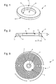
- the locking element 9, 109, 129, 209 is a washer whose inner wall 10 radially clamps the axis 2, 102, 122, 202 of the member 3, 103, 123, 203 and whose peripheral portion 13 exerts an axial and elastic force in line with the bearing surface 4 of the member 3, 103, 123, 203 in order to make integral the entire member 3, 103, 123, 203-piece 5, 105 , 205 - locking element 9, 109, 129, 209.
- the locking element 9, 109, 129, 209 has an upper surface 11 intended to come into contact with a preferably flat tool 15 and a lower surface 12 intended to come into contact with the upper surface of the Room 5, 105, 205.
- the locking element 9 is symmetrical, that is to say that the surfaces 11 and 12 may be indifferently the upper or lower. However, this symmetry is only optional and applied preferentially to avoid handling errors during manufacture.
- the elastic mounting of the locking element 9, 109, 129, 209 is advantageously obtained by using a third material which comprises a metal or a metal alloy whose resistance to relaxation is at least equal to 50% of the applied force.
- the tests making it possible to determine this percentage were carried out after 10'000 hours at a temperature of 70 ° C. and under a force of 75% of the stress necessary to obtain 0.2% of plastic deformation, that is to say substantially 75% of the elastic limit of the third material.
- This resistance greater than 50% was observed when the third material comprises copper, brass, nickel silver, arcap alloy and even greater than 85% when the third material comprises pfinodal alloy, spinodal alloy , durnico alloy, durimphy alloy, Cu-Be alloy and 20AP steel.
- the locking element 9, 109, 129, 209 is, even more preferably, selected from the above materials which do not have ferromagnetic properties so as to be insensitive to magnetic fields, that is to say copper, brass, nickel silver, arcap alloy, pfinodal alloy, spinodal alloy, Cu-Be alloy and durimphy alloy.
- the section along an axial section plane of the locking element 9, 109, 129, 209 comprises a ratio (H / L) of the height H with respect to the width L between 0, 1 and 5.
- H / L the ratio of the height H with respect to the width L between 0, 1 and 5.
- the locking element 9, 109, 129, 209 is chamfered to prevent breakage of the second material having no or little plastic field. Indeed, as explained below according to the geometry of the intermediate deformation, a chamfer can prevent the blocking element 9, 109, 129, 209 coming into contact on the upper surface of the part 5, 105, 205 by a sharp edge clean to generate too much stress and / or pressure on a minimum surface.
- said at least first material formed for the member 3, 103, 123, 203 may comprise a wide variety of material such as, for example, a metal or a metal alloy.
- the method comprises a first step a) of forming each part of the assembly system 1.
- the step a) comprises a phase intended to form a member 3 in at least a first material having an axis 2 and a bearing surface 4, whether shaped or not, a second phase intended to form a part 5 made of a second material having no or little plastic area, such as example, based on silicon with an opening 6 and a third phase intended to form a locking element 9 in the form of a washer based on a third material and whose hole 8 is smaller than the axis 2 of the organ 3.
- the order of execution of the phases is of no importance.
- step b) consisting of passing the axis 2 of the member 3 without constraint in the opening 6 of the part 5.
- This step b) is viewable at the figure 4 .
- Step c) continues the process and includes a first phase intended to place the axis 2 against the hole 8 of the locking element 9.
- This first phase of step c) can also be seen at figure 4 .
- a tool 15 is also noted.
- This tool 15 is preferably flat, that is to say has a substantially flat surface 14 intended to come into contact with the upper face 11 of the blocking element 9. if the locking element 9 is symmetrical as illustrated in FIGS. Figures 1 and 2 , the mounting errors between the upper face 11 and the lower face 12 are eliminated.
- Step c) continues with a second phase intended to force the locking element 9 against the axis 2 by means of the tool 15 in order to deform the locking element 9 so that the peripheral portion 13 of the blocking element 9 is closest to the part 5 as illustrated in FIG. figure 5 .
- this second phase could be likened to a chase.
- This elastic intermediate deformation which can cause occasional plastic deformations at the inner wall 10, gives the impression that the locking element 9 is a Belleville washer.
- this geometry is not stable, that is to say not a plastic deformation like creep, and only induced by the force of the tool 15.
- This elastic intermediate deformation is made maximum by the use of the hole 8 of the locking element 9 smaller than the axis 2 of the member 3 and the use of the tool 15 whose surface 14 is substantially planar.
- This elastic intermediate deformation is of great importance for the future assembly system 1 in that it applies the future axial stress to the part 5 as illustrated in FIG. figure 6 , not closer to the axis 2 but, via the lever arm width L of the locking element 9, at the peripheral portion 13 of the locking element 9. It is therefore clear that the section the bearing surface 4 of the member 3 must also preferably be substantially equal to or greater than that of the locking element 9 in order to allow the peripheral portion 13 to exert an axial and elastic force directly above the bearing surface 4 of the organ 3.
- the figure 3 is a graphical representation of the force applied by the tool 15 during the above process as a function of the axial position of the tool 15.
- the second phase of step c) begins as illustrated to the figure 5 .
- the peripheral portion 13 of the locking element 9 starts to pinch the piece 5 as illustrated in FIG. figure 6 .
- the inner wall 10 of the locking element 9 is brought as close as possible to the part 5 as illustrated in FIG. figure 7 and any additional force of the tool 15 exerts an internal stress of the locking element 9 without impacting the geometry of the locking element 9.
- FIG. figure 9 it is possible to fix a hairspring 5 on a balance shaft 2, using an assembly system 1 according to the invention. To do this, the ferrule 7 of the spiral 5 is secured between the pivot 3 and the locking element 9.
- step d) is stopped when the force applied by the tool 15 is between 20% and 90% of the stress of elastic limit of the third material.
- the percentage must be adapted according to the intended application.
- step d) was entirely satisfactory when the force applied by the tool 15 is substantially equal to 75% of the elastic limit stress of the third material.
- the elastic mounting of the locking element 9, 109, 129, 209 is advantageously obtained by using a third material which comprises a metal or a metal alloy whose resistance to relaxation is at least 50 % of the force applied.
- the tests to determine this percentage were performed after 10'000 hours at a temperature of 70 ° C and under a force of 75% of the stress necessary to obtain 0.2% of plastic deformation.
- the resistance greater than 50% was observed when the third material comprises copper, brass, nickel silver, arcap alloy, and even greater than 85%, when the third material comprises pfinodal alloy, spinodal alloy, durnico alloy, durimphy alloy, Cu-Be alloy and 20AP steel.
- the locking element 9, 109, 129, 209 is, even more preferably, selected from the above materials which do not have ferromagnetic material so as to be insensitive to magnetic fields, that is to say copper, brass, nickel silver, arcap alloy, pfinodal alloy, spinodal alloy, Cu-Be alloy and durimphy alloy.
- the section along an axial section plane of the locking element 9, 109, 129, 209 comprises a ratio (H / L) of the height H with respect to the width L between 0, 1 and 5.
- H / L the ratio of the height H with respect to the width L between 0, 1 and 5.
- the locking element 9, 109, 129, 209 is chamfered to prevent breakage of the second material. Indeed, as explained above according to the geometry of the intermediate deformation, a chamfer can prevent the blocking element 9, 109, 129, 209 coming into contact on the upper surface of the part 5, 105, 205 by a sharp edge clean to generate too much stress on a minimal surface.
- said at least one first material formed for the member 3, 103, 123, 203 may comprise a large variety of material such as, for example, a metal or a metal alloy. It is therefore understood that the axis 2, 102, 122, 202 and the bearing surface 4 can be integrally formed using a single first material or that the axis 2, 102, 122, 202 and the bearing surface 4 of the member 3, 103, 123, 203 may be formed from several materials and / or parts.
- the second material having no or little plastic domain can comprise, in particular, silicon, quartz, corundum, silicon oxide, silicon nitride or silicon carbide without risk of breakage.
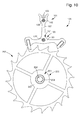
- FIG 10 shows other embodiments of assembly systems 101, 121, 201 according to the invention in the field of watchmaking.
- An anchor 105 may comprise two assembly systems 101, 121 according to the invention intended respectively to secure the stinger 103 and the rod 123, with the rod 107.
- each assembly system 101, 121 comprises the rod 107 which is secured between the axis 102 of the rod 103 or the axis 122 of the rod 123 and the locking element 109, 129. It is thus clear that each system of assembly 101, 121 is sufficiently resistant not to generate relative movements between its components.
- an escape wheel and more generally the wheel 205, includes, by way of example, an assembly system 201 for securing a pivot 203, with the wheel 205.
- the assembly system 201 comprises a hub 207 which is secured between the axis 202 of the pivot 203 and the locking element 209.
- the assembly system example 201 can be applied to any type of mobile.
- the axis 203 may comprise in one piece a pinion to form a finished mobile.
- the present invention is not limited to the illustrated example but is susceptible of various variations and modifications that will occur to those skilled in the art.
- the locking element 9, 109, 129, 209 may comprise a different geometry without departing from the scope of the invention.
- the tool 15 could also comprise a surface 14 substantially conical to substantially follow the shape of Belleville washer obtained during the intermediate elastic deformation.
- the opening 6 of the part 5, 105, 205 can not be limited to a circular shape and / or the part 5, 105, 205 may be partially perforated below the locking element 9, 109, 129 209.
- the hairspring 5 of the figure 9 could be replaced by the hairspring 10 having a shell 41 whose opening is substantially clover-shaped of the document EP 2 363 762 , incorporated by reference in the present patent application, without removing the advantages mentioned above.
- fragments materials than those based on silicon or alumina are conceivable, such as, for example, zirconium or titanium based ceramics, or glasses.
- the locking element 9, 109, 129, 209 may also be formed based on amorphous metals also called metallic glasses.
Landscapes
- Engineering & Computer Science (AREA)
- General Engineering & Computer Science (AREA)
- Physics & Mathematics (AREA)
- General Physics & Mathematics (AREA)
- Mechanical Engineering (AREA)
- Manufacturing & Machinery (AREA)
- Micromachines (AREA)
- Sliding-Contact Bearings (AREA)
- Metallurgy (AREA)
- Insertion Pins And Rivets (AREA)
- Gasket Seals (AREA)
- Connection Of Plates (AREA)
- Adornments (AREA)
Priority Applications (1)
| Application Number | Priority Date | Filing Date | Title |
|---|---|---|---|
| EP14184665.9A EP2860592B1 (de) | 2013-10-09 | 2014-09-12 | Montagesystem, bei dem ein flaches elastisches blockierelement verwendet wird |
Applications Claiming Priority (2)
| Application Number | Priority Date | Filing Date | Title |
|---|---|---|---|
| EP13187833 | 2013-10-09 | ||
| EP14184665.9A EP2860592B1 (de) | 2013-10-09 | 2014-09-12 | Montagesystem, bei dem ein flaches elastisches blockierelement verwendet wird |
Publications (2)
| Publication Number | Publication Date |
|---|---|
| EP2860592A1 true EP2860592A1 (de) | 2015-04-15 |
| EP2860592B1 EP2860592B1 (de) | 2023-07-05 |
Family
ID=49322267
Family Applications (1)
| Application Number | Title | Priority Date | Filing Date |
|---|---|---|---|
| EP14184665.9A Active EP2860592B1 (de) | 2013-10-09 | 2014-09-12 | Montagesystem, bei dem ein flaches elastisches blockierelement verwendet wird |
Country Status (6)
| Country | Link |
|---|---|
| US (1) | US9671755B2 (de) |
| EP (1) | EP2860592B1 (de) |
| JP (1) | JP5934323B2 (de) |
| CN (1) | CN104570684B (de) |
| HK (1) | HK1210281A1 (de) |
| RU (1) | RU2679451C2 (de) |
Cited By (1)
| Publication number | Priority date | Publication date | Assignee | Title |
|---|---|---|---|---|
| EP3309625A1 (de) | 2016-10-13 | 2018-04-18 | Nivarox-FAR S.A. | Spirale zur befestigung mit einer federscheibe |
Families Citing this family (12)
| Publication number | Priority date | Publication date | Assignee | Title |
|---|---|---|---|---|
| EP2952977A1 (de) * | 2014-06-03 | 2015-12-09 | Nivarox-FAR S.A. | Uhrkomponente aus geschweißten Materialien |
| EP3067756B1 (de) | 2015-03-09 | 2017-11-22 | Nivarox-FAR S.A. | Schwenkbare einheit für eine uhr |
| EP3106932A1 (de) * | 2015-06-16 | 2016-12-21 | Nivarox-FAR S.A. | Herstellungsverfahren, das einen modifizierten montageschritt umfasst |
| EP3106929A1 (de) * | 2015-06-16 | 2016-12-21 | Nivarox-FAR S.A. | Werkstück mit verbesserter schweissoberfläche |
| EP3106930A1 (de) * | 2015-06-16 | 2016-12-21 | Nivarox-FAR S.A. | Herstellungsverfahren, das einen modifizierten maschinenverarbeitungsschritt umfasst |
| EP3106931A1 (de) * | 2015-06-16 | 2016-12-21 | Nivarox-FAR S.A. | Werkstück mit entkoppelter schweissoberfläche |
| EP3106935A1 (de) * | 2015-06-16 | 2016-12-21 | Nivarox-FAR S.A. | Herstellungsverfahren eines werstücks, das einen modifizierten polierschritt umfasst |
| EP3106928A1 (de) * | 2015-06-16 | 2016-12-21 | Nivarox-FAR S.A. | Herstellungsverfahren, das einen modifizierten automatendreh-schritt umfasst |
| EP3118692B1 (de) * | 2015-07-16 | 2018-12-26 | Nivarox-FAR S.A. | Befestigung der spiralfeder eines uhrwerks durch verklebung |
| EP3176650B1 (de) * | 2015-12-02 | 2019-02-06 | Nivarox-FAR S.A. | Schutz einer uhrkomponente aus mikro-bearbeitbarem material |
| JP6891622B2 (ja) * | 2017-04-28 | 2021-06-18 | セイコーエプソン株式会社 | 機械部品及び時計 |
| EP3742236A1 (de) * | 2019-05-23 | 2020-11-25 | Rolex Sa | Uhrvorrichtung, die eine erste komponente umfasst, die auf einer zweiten komponente durch plastische verformung fixiert ist |
Citations (4)
| Publication number | Priority date | Publication date | Assignee | Title |
|---|---|---|---|---|
| EP1705533A1 (de) * | 2005-03-22 | 2006-09-27 | Patek Philippe S.A. | Zusammenbau eines Teils mit einer Achse |
| EP2273322A1 (de) * | 2009-07-10 | 2011-01-12 | Chopard Technologies SA | Montageverfahren eines Bauteils auf einem Schwenkorgan |
| EP2363762A1 (de) | 2010-03-04 | 2011-09-07 | Montres Breguet SA | Uhr mit einem mechanischen Hochfrequenzuhrwerk |
| CH703961A2 (fr) * | 2010-10-22 | 2012-04-30 | Manuf La Joux Perret Sa | Méthode d'assemblage d'une pièce en matériau dur sur un axe et ensemble comprenant une telle pièce assemblée sur un axe. |
Family Cites Families (22)
| Publication number | Priority date | Publication date | Assignee | Title |
|---|---|---|---|---|
| US2321157A (en) * | 1942-03-13 | 1943-06-08 | Illinois Tool Works | Fastener device |
| US2421115A (en) * | 1943-02-05 | 1947-05-27 | Frank L Lindstrom | Method of securing laminations on a rotor shaft |
| US3032807A (en) * | 1959-12-16 | 1962-05-08 | Illinois Tool Works | Spring retainer |
| US3762158A (en) * | 1971-08-25 | 1973-10-02 | H Forrester | Progress meter |
| US3827232A (en) * | 1972-12-11 | 1974-08-06 | Int Register Co | Spring driven timer |
| JPS5181907A (de) * | 1975-01-14 | 1976-07-17 | Citizen Watch Co Ltd | |
| US4834603A (en) * | 1977-05-03 | 1989-05-30 | Eaton Corporation | Stud and stud retaining fastener assembly |
| DE3717534A1 (de) * | 1987-05-25 | 1988-12-15 | Emitec Emissionstechnologie | Hohlwelle mit durch aufweiten derselben darauf befestigten antriebselementen mit axial unterschiedlichen werkstoffeigenschaften |
| US4795930A (en) * | 1987-12-03 | 1989-01-03 | Timex Corporation | Stepping motor coil core and stator assembly for a timepiece |
| US5195860A (en) * | 1992-07-20 | 1993-03-23 | Trw Inc. | Push-on type fastener for automatic feed and installation equipment |
| US5987749A (en) * | 1992-09-21 | 1999-11-23 | U.S. Philips Corporation | Method of manufacturing a dynamic groove bearing, die suitable for use in such a method, and housing and bearing part manufactured by such a method |
| US5584631A (en) * | 1993-03-23 | 1996-12-17 | The Beta Group | Optimized elastic fastener useful in eyeglass frames |
| US5395193A (en) * | 1993-03-23 | 1995-03-07 | The Beta Group | Optimized elastic belleville fastener useful in eyeglass frames |
| US5803692A (en) * | 1996-05-23 | 1998-09-08 | Trans Technology Corp. | Pushnut for use in conjunction with a cylindrical shaft having a pair of opposed flat surfaces |
| JPH1047328A (ja) * | 1996-07-29 | 1998-02-17 | Topy Fastener Kogyo Kk | プッシュナット |
| DE29802806U1 (de) * | 1998-02-18 | 1998-04-16 | Kieninger Uhrenfabrik Gmbh | Kettenradbaugruppe für den Gewichtsantrieb einer Uhr |
| DE19950214A1 (de) * | 1999-10-19 | 2001-05-10 | Bosch Gmbh Robert | Aus einem Halteelement und einer Scheiben-Wischvorrichtung bestehende Baueinheit |
| US6705813B2 (en) * | 2002-02-07 | 2004-03-16 | Pierre P. Schwab | Snap disc device |
| JP4286503B2 (ja) * | 2002-08-09 | 2009-07-01 | 日産自動車株式会社 | 取付クリップ及び該取付クリップを用いた取付構造 |
| EP1850193B1 (de) * | 2006-04-28 | 2019-06-12 | Patek Philippe SA Genève | Verfahren zur Einpressung eines Teils in ein anderes Teil |
| US20080037374A1 (en) * | 2006-08-09 | 2008-02-14 | Lee Bou Label Enterprise Co., Ltd. | Portable time display device |
| JP2012063162A (ja) * | 2010-09-14 | 2012-03-29 | Seiko Instruments Inc | 時計用歯車及び時計 |
-
2014
- 2014-09-12 EP EP14184665.9A patent/EP2860592B1/de active Active
- 2014-10-07 US US14/508,268 patent/US9671755B2/en active Active
- 2014-10-07 JP JP2014206122A patent/JP5934323B2/ja active Active
- 2014-10-08 RU RU2014140817A patent/RU2679451C2/ru active
- 2014-10-09 CN CN201410527950.XA patent/CN104570684B/zh active Active
-
2015
- 2015-10-28 HK HK15110664.7A patent/HK1210281A1/xx unknown
Patent Citations (4)
| Publication number | Priority date | Publication date | Assignee | Title |
|---|---|---|---|---|
| EP1705533A1 (de) * | 2005-03-22 | 2006-09-27 | Patek Philippe S.A. | Zusammenbau eines Teils mit einer Achse |
| EP2273322A1 (de) * | 2009-07-10 | 2011-01-12 | Chopard Technologies SA | Montageverfahren eines Bauteils auf einem Schwenkorgan |
| EP2363762A1 (de) | 2010-03-04 | 2011-09-07 | Montres Breguet SA | Uhr mit einem mechanischen Hochfrequenzuhrwerk |
| CH703961A2 (fr) * | 2010-10-22 | 2012-04-30 | Manuf La Joux Perret Sa | Méthode d'assemblage d'une pièce en matériau dur sur un axe et ensemble comprenant une telle pièce assemblée sur un axe. |
Cited By (1)
| Publication number | Priority date | Publication date | Assignee | Title |
|---|---|---|---|---|
| EP3309625A1 (de) | 2016-10-13 | 2018-04-18 | Nivarox-FAR S.A. | Spirale zur befestigung mit einer federscheibe |
Also Published As
| Publication number | Publication date |
|---|---|
| HK1210281A1 (en) | 2016-04-15 |
| JP5934323B2 (ja) | 2016-06-15 |
| RU2014140817A (ru) | 2016-04-27 |
| JP2015075491A (ja) | 2015-04-20 |
| EP2860592B1 (de) | 2023-07-05 |
| CN104570684A (zh) | 2015-04-29 |
| RU2679451C2 (ru) | 2019-02-11 |
| RU2014140817A3 (de) | 2018-06-07 |
| CN104570684B (zh) | 2017-08-08 |
| US9671755B2 (en) | 2017-06-06 |
| US20150098311A1 (en) | 2015-04-09 |
Similar Documents
| Publication | Publication Date | Title |
|---|---|---|
| EP2860592B1 (de) | Montagesystem, bei dem ein flaches elastisches blockierelement verwendet wird | |
| EP2743782B1 (de) | Vorrichtung zum zusammenbau von elastischen armen durch verformung | |
| EP2860591A1 (de) | Montagesystem, bei dem ein konisches elastisches Blockierelement verwendet wird | |
| EP2656151B1 (de) | Montage einer komponente ohne kunststoffbereich | |
| EP2469355B1 (de) | Zusammenbau eines Teils, das keinen Plastikbereich enthält | |
| EP2469354B1 (de) | Zusammenbau eines Teils, das keinen Plastikbereich enthält | |
| EP2656150B1 (de) | Montageverfahren einer komponente ohne kunststoffbereich | |
| EP2442189A1 (de) | Zusammenbauverfahren für ein Teil, das keinen Plastizitätsbereich enthält | |
| EP2743781B1 (de) | Montagevorrichtung zum Verriegeln eines Verbundsystems | |
| EP3115852B1 (de) | Uhrkomponente mit einem teil mit verbesserter schweissoberfläche | |
| EP3112951B1 (de) | Herstellungsverfahren, das einen modifizierten bearbeitungsschritt umfasst | |
| EP3112950B1 (de) | Herstellungsverfahren, das einen modifizierten automatendreh-schritt umfasst | |
| EP3112955B1 (de) | Herstellungsverfahren eines werkstücks, das einen modifizierten polierschritt umfasst | |
| CH708670A2 (fr) | Système d'assemblage utilisant un élément de blocage élastique conique. | |
| CH708669A2 (fr) | Système d'assemblage utilisant un élément de blocage élastique plan. | |
| CH707341A2 (fr) | Dispositif d'assemblage par verrouillage d'un emboîtement et pièce d'horlogerie comportant un tel dispositif. | |
| EP3112952B1 (de) | Herstellungsverfahren, das einen modifizierten montageschritt umfasst | |
| CH704257B1 (fr) | Assemblage d'une pièce fragile ne comportant pas de domaine plastique. | |
| CH700625A2 (fr) | Système de serrage radial pour un composant horloger. | |
| CH707342A2 (fr) | Dispositif d'assemblage par déformation de bras élastiques et pièce d'horlogerie comportant un tel dispositif. | |
| CH711214A2 (fr) | Procédé de fabrication d'une pièce comportant une étape de brunissage. |
Legal Events
| Date | Code | Title | Description |
|---|---|---|---|
| PUAI | Public reference made under article 153(3) epc to a published international application that has entered the european phase |
Free format text: ORIGINAL CODE: 0009012 |
|
| 17P | Request for examination filed |
Effective date: 20140912 |
|
| AK | Designated contracting states |
Kind code of ref document: A1 Designated state(s): AL AT BE BG CH CY CZ DE DK EE ES FI FR GB GR HR HU IE IS IT LI LT LU LV MC MK MT NL NO PL PT RO RS SE SI SK SM TR |
|
| AX | Request for extension of the european patent |
Extension state: BA ME |
|
| STAA | Information on the status of an ep patent application or granted ep patent |
Free format text: STATUS: REQUEST FOR EXAMINATION WAS MADE |
|
| R17P | Request for examination filed (corrected) |
Effective date: 20151015 |
|
| RBV | Designated contracting states (corrected) |
Designated state(s): AL AT BE BG CH CY CZ DE DK EE ES FI FR GB GR HR HU IE IS IT LI LT LU LV MC MK MT NL NO PL PT RO RS SE SI SK SM TR |
|
| STAA | Information on the status of an ep patent application or granted ep patent |
Free format text: STATUS: EXAMINATION IS IN PROGRESS |
|
| 17Q | First examination report despatched |
Effective date: 20210412 |
|
| STAA | Information on the status of an ep patent application or granted ep patent |
Free format text: STATUS: EXAMINATION IS IN PROGRESS |
|
| GRAP | Despatch of communication of intention to grant a patent |
Free format text: ORIGINAL CODE: EPIDOSNIGR1 |
|
| STAA | Information on the status of an ep patent application or granted ep patent |
Free format text: STATUS: GRANT OF PATENT IS INTENDED |
|
| INTG | Intention to grant announced |
Effective date: 20230418 |
|
| GRAS | Grant fee paid |
Free format text: ORIGINAL CODE: EPIDOSNIGR3 |
|
| GRAA | (expected) grant |
Free format text: ORIGINAL CODE: 0009210 |
|
| STAA | Information on the status of an ep patent application or granted ep patent |
Free format text: STATUS: THE PATENT HAS BEEN GRANTED |
|
| AK | Designated contracting states |
Kind code of ref document: B1 Designated state(s): AL AT BE BG CH CY CZ DE DK EE ES FI FR GB GR HR HU IE IS IT LI LT LU LV MC MK MT NL NO PL PT RO RS SE SI SK SM TR |
|
| REG | Reference to a national code |
Ref country code: CH Ref legal event code: EP |
|
| REG | Reference to a national code |
Ref country code: AT Ref legal event code: REF Ref document number: 1585405 Country of ref document: AT Kind code of ref document: T Effective date: 20230715 |
|
| P01 | Opt-out of the competence of the unified patent court (upc) registered |
Effective date: 20230611 |
|
| REG | Reference to a national code |
Ref country code: DE Ref legal event code: R096 Ref document number: 602014087518 Country of ref document: DE |
|
| REG | Reference to a national code |
Ref country code: IE Ref legal event code: FG4D Free format text: LANGUAGE OF EP DOCUMENT: FRENCH |
|
| REG | Reference to a national code |
Ref country code: LT Ref legal event code: MG9D |
|
| PGFP | Annual fee paid to national office [announced via postgrant information from national office to epo] |
Ref country code: GB Payment date: 20230823 Year of fee payment: 10 |
|
| REG | Reference to a national code |
Ref country code: NL Ref legal event code: MP Effective date: 20230705 |
|
| PGFP | Annual fee paid to national office [announced via postgrant information from national office to epo] |
Ref country code: FR Payment date: 20230822 Year of fee payment: 10 Ref country code: DE Payment date: 20230822 Year of fee payment: 10 |
|
| REG | Reference to a national code |
Ref country code: AT Ref legal event code: MK05 Ref document number: 1585405 Country of ref document: AT Kind code of ref document: T Effective date: 20230705 |
|
| PG25 | Lapsed in a contracting state [announced via postgrant information from national office to epo] |
Ref country code: NL Free format text: LAPSE BECAUSE OF FAILURE TO SUBMIT A TRANSLATION OF THE DESCRIPTION OR TO PAY THE FEE WITHIN THE PRESCRIBED TIME-LIMIT Effective date: 20230705 |
|
| PG25 | Lapsed in a contracting state [announced via postgrant information from national office to epo] |
Ref country code: GR Free format text: LAPSE BECAUSE OF FAILURE TO SUBMIT A TRANSLATION OF THE DESCRIPTION OR TO PAY THE FEE WITHIN THE PRESCRIBED TIME-LIMIT Effective date: 20231006 |
|
| PG25 | Lapsed in a contracting state [announced via postgrant information from national office to epo] |
Ref country code: ES Free format text: LAPSE BECAUSE OF FAILURE TO SUBMIT A TRANSLATION OF THE DESCRIPTION OR TO PAY THE FEE WITHIN THE PRESCRIBED TIME-LIMIT Effective date: 20230705 |
|
| PG25 | Lapsed in a contracting state [announced via postgrant information from national office to epo] |
Ref country code: IS Free format text: LAPSE BECAUSE OF FAILURE TO SUBMIT A TRANSLATION OF THE DESCRIPTION OR TO PAY THE FEE WITHIN THE PRESCRIBED TIME-LIMIT Effective date: 20231105 |
|
| PG25 | Lapsed in a contracting state [announced via postgrant information from national office to epo] |
Ref country code: SE Free format text: LAPSE BECAUSE OF FAILURE TO SUBMIT A TRANSLATION OF THE DESCRIPTION OR TO PAY THE FEE WITHIN THE PRESCRIBED TIME-LIMIT Effective date: 20230705 Ref country code: RS Free format text: LAPSE BECAUSE OF FAILURE TO SUBMIT A TRANSLATION OF THE DESCRIPTION OR TO PAY THE FEE WITHIN THE PRESCRIBED TIME-LIMIT Effective date: 20230705 Ref country code: PT Free format text: LAPSE BECAUSE OF FAILURE TO SUBMIT A TRANSLATION OF THE DESCRIPTION OR TO PAY THE FEE WITHIN THE PRESCRIBED TIME-LIMIT Effective date: 20231106 Ref country code: NO Free format text: LAPSE BECAUSE OF FAILURE TO SUBMIT A TRANSLATION OF THE DESCRIPTION OR TO PAY THE FEE WITHIN THE PRESCRIBED TIME-LIMIT Effective date: 20231005 Ref country code: LV Free format text: LAPSE BECAUSE OF FAILURE TO SUBMIT A TRANSLATION OF THE DESCRIPTION OR TO PAY THE FEE WITHIN THE PRESCRIBED TIME-LIMIT Effective date: 20230705 Ref country code: LT Free format text: LAPSE BECAUSE OF FAILURE TO SUBMIT A TRANSLATION OF THE DESCRIPTION OR TO PAY THE FEE WITHIN THE PRESCRIBED TIME-LIMIT Effective date: 20230705 Ref country code: IS Free format text: LAPSE BECAUSE OF FAILURE TO SUBMIT A TRANSLATION OF THE DESCRIPTION OR TO PAY THE FEE WITHIN THE PRESCRIBED TIME-LIMIT Effective date: 20231105 Ref country code: HR Free format text: LAPSE BECAUSE OF FAILURE TO SUBMIT A TRANSLATION OF THE DESCRIPTION OR TO PAY THE FEE WITHIN THE PRESCRIBED TIME-LIMIT Effective date: 20230705 Ref country code: GR Free format text: LAPSE BECAUSE OF FAILURE TO SUBMIT A TRANSLATION OF THE DESCRIPTION OR TO PAY THE FEE WITHIN THE PRESCRIBED TIME-LIMIT Effective date: 20231006 Ref country code: FI Free format text: LAPSE BECAUSE OF FAILURE TO SUBMIT A TRANSLATION OF THE DESCRIPTION OR TO PAY THE FEE WITHIN THE PRESCRIBED TIME-LIMIT Effective date: 20230705 Ref country code: ES Free format text: LAPSE BECAUSE OF FAILURE TO SUBMIT A TRANSLATION OF THE DESCRIPTION OR TO PAY THE FEE WITHIN THE PRESCRIBED TIME-LIMIT Effective date: 20230705 Ref country code: AT Free format text: LAPSE BECAUSE OF FAILURE TO SUBMIT A TRANSLATION OF THE DESCRIPTION OR TO PAY THE FEE WITHIN THE PRESCRIBED TIME-LIMIT Effective date: 20230705 |
|
| PGFP | Annual fee paid to national office [announced via postgrant information from national office to epo] |
Ref country code: CH Payment date: 20231001 Year of fee payment: 10 |
|
| PG25 | Lapsed in a contracting state [announced via postgrant information from national office to epo] |
Ref country code: PL Free format text: LAPSE BECAUSE OF FAILURE TO SUBMIT A TRANSLATION OF THE DESCRIPTION OR TO PAY THE FEE WITHIN THE PRESCRIBED TIME-LIMIT Effective date: 20230705 |
|
| REG | Reference to a national code |
Ref country code: DE Ref legal event code: R097 Ref document number: 602014087518 Country of ref document: DE |
|
| PG25 | Lapsed in a contracting state [announced via postgrant information from national office to epo] |
Ref country code: SM Free format text: LAPSE BECAUSE OF FAILURE TO SUBMIT A TRANSLATION OF THE DESCRIPTION OR TO PAY THE FEE WITHIN THE PRESCRIBED TIME-LIMIT Effective date: 20230705 Ref country code: RO Free format text: LAPSE BECAUSE OF FAILURE TO SUBMIT A TRANSLATION OF THE DESCRIPTION OR TO PAY THE FEE WITHIN THE PRESCRIBED TIME-LIMIT Effective date: 20230705 Ref country code: EE Free format text: LAPSE BECAUSE OF FAILURE TO SUBMIT A TRANSLATION OF THE DESCRIPTION OR TO PAY THE FEE WITHIN THE PRESCRIBED TIME-LIMIT Effective date: 20230705 Ref country code: DK Free format text: LAPSE BECAUSE OF FAILURE TO SUBMIT A TRANSLATION OF THE DESCRIPTION OR TO PAY THE FEE WITHIN THE PRESCRIBED TIME-LIMIT Effective date: 20230705 Ref country code: CZ Free format text: LAPSE BECAUSE OF FAILURE TO SUBMIT A TRANSLATION OF THE DESCRIPTION OR TO PAY THE FEE WITHIN THE PRESCRIBED TIME-LIMIT Effective date: 20230705 Ref country code: SK Free format text: LAPSE BECAUSE OF FAILURE TO SUBMIT A TRANSLATION OF THE DESCRIPTION OR TO PAY THE FEE WITHIN THE PRESCRIBED TIME-LIMIT Effective date: 20230705 |
|
| PLBE | No opposition filed within time limit |
Free format text: ORIGINAL CODE: 0009261 |
|
| STAA | Information on the status of an ep patent application or granted ep patent |
Free format text: STATUS: NO OPPOSITION FILED WITHIN TIME LIMIT |
|
| PG25 | Lapsed in a contracting state [announced via postgrant information from national office to epo] |
Ref country code: LU Free format text: LAPSE BECAUSE OF NON-PAYMENT OF DUE FEES Effective date: 20230912 |
|
| REG | Reference to a national code |
Ref country code: BE Ref legal event code: MM Effective date: 20230930 |
|
| PG25 | Lapsed in a contracting state [announced via postgrant information from national office to epo] |
Ref country code: LU Free format text: LAPSE BECAUSE OF NON-PAYMENT OF DUE FEES Effective date: 20230912 Ref country code: IT Free format text: LAPSE BECAUSE OF FAILURE TO SUBMIT A TRANSLATION OF THE DESCRIPTION OR TO PAY THE FEE WITHIN THE PRESCRIBED TIME-LIMIT Effective date: 20230705 Ref country code: MC Free format text: LAPSE BECAUSE OF FAILURE TO SUBMIT A TRANSLATION OF THE DESCRIPTION OR TO PAY THE FEE WITHIN THE PRESCRIBED TIME-LIMIT Effective date: 20230705 |
|
| 26N | No opposition filed |
Effective date: 20240408 |
|
| REG | Reference to a national code |
Ref country code: IE Ref legal event code: MM4A |
|
| PG25 | Lapsed in a contracting state [announced via postgrant information from national office to epo] |
Ref country code: IE Free format text: LAPSE BECAUSE OF NON-PAYMENT OF DUE FEES Effective date: 20230912 |
|
| PG25 | Lapsed in a contracting state [announced via postgrant information from national office to epo] |
Ref country code: IE Free format text: LAPSE BECAUSE OF NON-PAYMENT OF DUE FEES Effective date: 20230912 Ref country code: SI Free format text: LAPSE BECAUSE OF FAILURE TO SUBMIT A TRANSLATION OF THE DESCRIPTION OR TO PAY THE FEE WITHIN THE PRESCRIBED TIME-LIMIT Effective date: 20230705 |
|
| PG25 | Lapsed in a contracting state [announced via postgrant information from national office to epo] |
Ref country code: BE Free format text: LAPSE BECAUSE OF NON-PAYMENT OF DUE FEES Effective date: 20230930 |