EP2860552B1 - Radiation dosimeter and radiation dose calculation method - Google Patents
Radiation dosimeter and radiation dose calculation method Download PDFInfo
- Publication number
- EP2860552B1 EP2860552B1 EP13800595.4A EP13800595A EP2860552B1 EP 2860552 B1 EP2860552 B1 EP 2860552B1 EP 13800595 A EP13800595 A EP 13800595A EP 2860552 B1 EP2860552 B1 EP 2860552B1
- Authority
- EP
- European Patent Office
- Prior art keywords
- radiation
- energy
- dose
- shield member
- spectrum
- Prior art date
- Legal status (The legal status is an assumption and is not a legal conclusion. Google has not performed a legal analysis and makes no representation as to the accuracy of the status listed.)
- Active
Links
Images

Classifications
-
- G—PHYSICS
- G01—MEASURING; TESTING
- G01T—MEASUREMENT OF NUCLEAR OR X-RADIATION
- G01T1/00—Measuring X-radiation, gamma radiation, corpuscular radiation, or cosmic radiation
- G01T1/02—Dosimeters
- G01T1/026—Semiconductor dose-rate meters
-
- G—PHYSICS
- G01—MEASURING; TESTING
- G01T—MEASUREMENT OF NUCLEAR OR X-RADIATION
- G01T1/00—Measuring X-radiation, gamma radiation, corpuscular radiation, or cosmic radiation
- G01T1/16—Measuring radiation intensity
- G01T1/24—Measuring radiation intensity with semiconductor detectors
- G01T1/244—Auxiliary details, e.g. casings, cooling, damping or insulation against damage by, e.g. heat, pressure or the like
Definitions
- the present invention relates to a radiation dosimeter and a radiation dose calculation method.
- a radiation dosimeter provided with a radiation detector using a semiconductor is available.
- detection sensitivity to radiation energy differs depending on the semiconductor used for the radiation detector.
- the detection sensitivity to radiation in a lower energy range is higher than the detection sensitivity to radiation in a higher energy range.
- the detection sensitivity and the dose measurement accuracy to higher energy radiation are required to be improved.
- Patent Literature 1 describes a radiation detector including a semiconductor detector covered by an electromagnetic shield, which serves as a radiation absorbing filter that absorbs a certain amount of radiation in a low energy range, to improve the uniformity of detection sensitivity to energy, and a scintillator layer and a reflection layer provided on a surface opposite to the incidence surface of the semiconductor detector.
- the scintillator layer emits light due to high-energy radiation passing through the semiconductor detector, and the emitted light is reflected by the reflection layer and is detected by the semiconductor detector.
- US4859853 discloses a solid state gamma ray dosimeter which measures radiation in terms of absorption in a material different from the detector material.
- a solid state detector, an amplifier, an analog-to-digital interface and a microprocessor are combined in circuit to correct for differences between absorption of radiation in detector material and absorption in other materials, especially tissue.
- a suitable cladding may surround the detector.
- a method of generating dose translation data for calibrating the microprocessor is also disclosed.
- the solid state detector is attached to a multichannel analyzer circuit and subject to known doses of various monochromatic gamma rays. Output pulses from the detector are amplified and introduced into the multichannel analyzer.
- the spectrum produced is used to determine an average channel number (or pulse height) for a given dose of monochromatic radiation.
- the given dose is in units specific to material different from the detector material.
- the partial dose represented by a single detector pulse at that energy is computed. Partial doses for other energies are likewise computed.
- Dose translation data associates a partial dose with a given detector pulse height. Dose translation data is set in the microprocessor of the dosimeter. Such dose translation data can be used to calculate total dose and dose rate in units peculiar to material other than detector material.
- US2011051901 relates to a device and method for determining one or more characteristics of radiation using a sensor comprising one or more detector units capable of counting the number of photon or charged particle of said radiation impinging on said sensor in or above a determined energy range.
- US4461952 relates to a portable computing device comprising, in known manner, means for adding digital information, means for determining periods of time and display means, wherein it also comprises a nuclear detector adapted to deliver electrical signals whose amplitude spectrum depends biunivocally on the energy spectrum of the radiation in which it is placed and means for converting these signals into digital information, the addition means receiving said digital information, the means for determining periods of time controlling said addition means so as to make a calculation of the dose of nuclear radiation received during a period of time, called integral dose, which is displayed by said display means.
- the invention is more particularly applicable in the domain of protection against radiation, or health physics.
- Solid-state personal dosimeter using dose conversion algorithm by Lee B. J. et al. relates to the design and testing of a personal dosimeter based on a silicon PIN photodiode.
- Patent Literature 1 Japanese Patent Application Laid-Open Publication No. 2001-4754
- the radiation detector described in Patent Literature 1 needs to include the scintillator layer and the reflection layer to improve the detection sensitivity to radiation in a high energy range and the accuracy of dose measurement. Accordingly, the structure becomes more complicated and the device becomes larger.
- a radiation dosimeter and a radiation dose calculation method are provided that enable the accuracy of dose measurement to be improved with a simple structure.
- a radiation dosimeter according to claim 1 is provided.
- the detection sensitivity to radiation can be improved when using a radiation detector with which the absorptance (detection sensitivity) in an energy range lower than the energy of radiation before being scattered is higher than the absorptance in the energy of radiation before being scattered.
- the radiation detector may comprise CdTe.
- the CdTe semiconductor has a high efficiency of absorbing radiation. This high efficiency can further improve the detection sensitivity to radiation and can further improve the accuracy of dose measurement.
- the shield member also may have a thickness of 0.1 millimeter or more and 1.0 millimeter or less. When such a shield member covers the radiation detector, the detection sensitivity to radiation can be improved and the accuracy of dose measurement can be improved.
- the radiation dosimeter may further include a display unit that displays the dose calculated by the arithmetic unit. In this case, displaying an accurately measured dose on the display unit can let a user know more accurate dose.
- a radiation dose calculation method according to claim 5 is provided.
- incident radiation is scattered by the shield member covering the radiation detector.
- the energy spectrum of this scattered radiation is distributed at a certain percentage in an energy range lower than the energy of radiation before being scattered.
- the detection sensitivity to radiation can be improved when using a radiation detector with which the absorptance in an energy range lower than the energy of radiation before being scattered is higher than the absorptance in the energy of radiation before being scattered.
- the dose when the shield member does not exist i.e., the net dose directly absorbed into a human body, can be calculated.
- the present invention can improve the dose measurement accuracy.
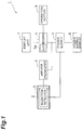
- Fig. 1 is a schematic block diagram of a radiation dosimeter according to a present embodiment.
- this radiation dosimeter 1 is a device that measures a radiation dose, and includes a radiation detector 2, a shield member 3, an amplifier 4, a microcomputer 5 (arithmetic unit), an operation button 6, a display unit 7, a power supply 8, and a power supply switch 9.
- a dose to be measured a sievert (Sv) value, for example, is used.
- the radiation detector 2 is a detector made of a semiconductor that can detect radiation, and comprises cadmium telluride (CdTe), for example.
- the thickness of the radiation detector 2 is about 1 millimeter, for example.
- one surface and the other surface of the semiconductor that can detect radiation are provided with respective electrodes (not depicted).
- the radiation detector 2 when energy of incident radiation is absorbed, an electron and a hole are generated depending on the magnitude of the energy. Subsequently, the radiation detector 2 outputs a detection signal having a voltage value depending on the magnitude of the energy to the microcomputer 5 via the amplifier 4.
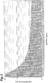
- Fig. 2 is a diagram illustrating one example of energy response of the radiation detector 2.
- the energy response herein means a relation between the energy of radiation and the absorptance of radiation, and is also referred to as a response function.
- the abscissa represents the energy of radiation and the ordinate represents the absorptance of radiation.
- the radiation detector 2 comprise CdTe, and the thickness thereof is 1 millimeter.
- the absorptance of radiation in lower energy ranges is higher than the absorptance of radiation in higher energy ranges, and the absorptance of radiation increases as the energy of radiation decreases.
- cesium 137 emits a gamma ray having an energy of 662 keV.
- the radiation detector 2 in this example is used alone, because the absorptance of gamma rays emitted from cesium 137 is about 0.7%, the detection sensitivity thereto is significantly low.
- the shield member 3 is a metallic sheet-like member, and comprises any of gold (Au), and stainless steel.
- the shield member 3 has a thickness of 0.1 millimeter or more, for example, and has a thickness of 1.0 millimeter or less, for example.
- the shield member 3 is provided so as to cover a surface of the radiation detector 2. Between the shield member 3 and the radiation detector 2, a gap of about 0.1 millimeter to 1 millimeter is provided.
- the amplifier 4 is a signal amplifier (preamplifier) that amplifies a detection signal output from the radiation detector 2. The amplifier 4 outputs the amplified detection signal to the microcomputer 5.
- the microcomputer 5 is an arithmetic unit that calculates a dose on the basis of radiation detected by the radiation detector 2.
- the microcomputer 5 receives a detection signal amplified by the amplifier 4, and generates an energy spectrum depending on the voltage value of the detection signal received.
- the microcomputer 5 also performs a certain computation on the energy spectrum to calculate a radiation dose.
- the microcomputer 5 then outputs display information on the calculated dose to be displayed on the display unit 7.
- the microcomputer 5 has an ADC 5a.
- the ADC 5a converts the voltage value of the received detection signal into a channel.
- the channel herein means a memory address that corresponds to the magnitude of energy.
- an energy spectrum represents a relation between energy and the strength of the energy, and the strength of energy is represented by a count value that is the number of incidences of radiation having the energy.
- count values of respective energies are stored in sequential addresses (channels) of the memory. More specifically, every time the microcomputer 5 receives a detection signal from the radiation detector 2 via the amplifier 4, the microcomputer 5 converts the voltage value of the detection signal into a channel with the ADC 5a and increments the count value stored in the converted channel by one. In this manner, the microcomputer 5 acquires a channel spectrum. The microcomputer 5 then converts the channel into energy for display, for example, to convert the channel spectrum into an energy spectrum. Details of functions of the microcomputer 5 will be described later.
- the operation button 6 is an input device for operating the radiation dosimeter 1.
- the operation button 6 includes, for example, an operation button for selecting operation modes (accumulation mode, real-time mode) of the radiation dosimeter 1 and an operation button for providing instructions for determination.
- Examples of the operation modes of the radiation dosimeter 1 include an initializing mode, an accumulation mode, and a real-time mode.
- the initializing mode is an operation mode for initializing a conversion factor to calibrate the detection sensitivity of the radiation dosimeter 1.
- the initializing mode is activated by, for example, operation of selecting the initializing mode among the operation modes displayed on the display unit 7, and operation of pushing down the power supply switch 9 while pushing a certain button of the operation button 6 to start up the radiation dosimeter 1. This process of initializing the conversion factor in the initializing mode is performed by a manufacturer or a dealer at shipment of the product, for example.
- the accumulation mode is a mode for displaying a radiation dose (Sv) measured during a period from a power-ON state to a power-OFF state.
- the real-time mode is a mode for displaying a radiation dose rate (Sv/h) measured in the power-ON state.
- the display unit 7 is a display unit such as a liquid crystal display. This display unit 7 displays predetermined information on the basis of the display information output by the microcomputer 5. For example, the display unit 7 displays the dose calculated by the microcomputer 5 and the state of the power supply 8.
- the power supply 8 supplies power to each component of the radiation dosimeter 1.
- the power supply 8 can be switched between the ON state and the OFF state by operating the power supply switch 9.
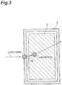
- Fig. 3 is a diagram illustrating a cross section of the radiation detector 2 and the shield member 3. As depicted in Fig. 3 , the radiation detector 2 is covered by the shield member 3.
- the radiation dosimeter 1 when a radiation r1 in the atmosphere enters the shield member 3, Compton scattering occurs in the shield member 3.
- the energy of a radiation r2 after the scattering is equal to or lower than the energy of the radiation r1, and is distributed at a certain percentage in energy ranges lower than the energy of the radiation r1 before the scattering.
- Part of the radiation r2 after the scattering is absorbed by the radiation detector 2.
- the radiation r2 passing through the radiation detector 2 without being absorbed passes through the shield member 3 to exit to the outside.
- the absorptance of radiation in lower energy ranges is higher than the absorptance of radiation in higher energy ranges.
- the absorptance of the radiation r2 is higher than the absorptance of the radiation r1. Consequently, the absorptance of radiation in the radiation detector 2 improves, and the detection sensitivity to radiation improves.
- stainless steel contained 1% of silicon (Si), 18% of chrome (Cr), 2% of manganese (Mn), 70% of iron (Fe), and 9% of nickel (Ni), and the density of the stainless steel was 7.93 g/cm 3 .
- the radiation detector 2 comprised CdTe, and the thickness thereof was 1 millimeter. Between the radiation detector 2 and the shield member 3, a gap of about 0.1 millimeter to 1.0 millimeter was provided.
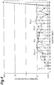
- Fig. 4 is a diagram illustrating one example of energy spectra of scattered radiation when the thickness of various shield members 3 (Au, Al, stainless steel, and Cu) was 0.1 millimeter.
- the abscissa represents the energy of radiation incident into the radiation detector 2
- the ordinate represents the ratio (distribution ratio) of the number of incidences of radiation for each energy to the total number of incidences of radiation.
- the graph G Au01 indicates an energy spectrum of scattered radiation when the shield member 3 was Au having a thickness of 0.1 millimeter.
- the graph G Al101 indicates an energy spectrum of scattered radiation when the shield member 3 was Al having a thickness of 0.1 millimeter.
- the graph G SUS01 indicates an energy spectrum of scattered radiation when the shield member 3 was stainless steel having a thickness of 0.1 millimeter.
- the graph G Cu01 indicates an energy spectrum of scattered radiation when the shield member 3 was Cu having a thickness of 0.1 millimeter.
- the energy spectra of these scattered radiations indicate energy spectra after radiations each having an energy of 662 keV were scattered by the respective shield members 3.
- the shield member 3 when the shield member 3 was Au having a thickness of 0.1 millimeter, the distribution ratio of energy near 662 keV was close to 100%, the distribution ratio of energy of 200 keV to 660 keV was about 0.1%, the distribution ratio of energy of 200 keV or less was about 0.01 to 0.08%.
- the shield member 3 was Al having a thickness of 0.1 millimeter, the distribution ratio of energy near 662 keV was close to 100%, the distribution ratio of energy of 660 keV or less was about 0 to 0.05%.
- the shield member 3 was stainless steel having a thickness of 0.1 millimeter, the distribution ratio of energy near 662 keV was close to 100%, the distribution ratio of energy of 200 keV to 660 keV was about 0.04 to 0.09%, the distribution ratio of energy of 200 keV or less was about 0.01 to 0.02%.
- the shield member 3 was Cu having a thickness of 0.1 millimeter, the distribution ratio of energy near 662 keV was close to 100%, the distribution ratio of energy of 200 keV to 660 keV was about 0.04 to 0.09%, the distribution ratio of energy of 200 keV or less was about 0.01 to 0.04%.
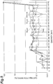
- Fig. 5 is a diagram illustrating one example of energy spectra of scattered radiation when the thickness of various shield members 3 was 0.5 millimeter.
- the graph G Au05 indicates an energy spectrum of scattered radiation when the shield member 3 was Au having a thickness of 0.5 millimeter.
- the graph G Al05 indicates an energy spectrum of scattered radiation when the shield member 3 was Al having a thickness of 0.5 millimeter.
- the graph G SUS05 indicates an energy spectrum of scattered radiation when the shield member 3 was stainless steel having a thickness of 0.5 millimeter.
- the graph G Cu05 indicates an energy spectrum of scattered radiation when the shield member 3 was Cu having a thickness of 0.5 millimeter.
- the energy spectra of these scattered radiations indicate energy spectra after radiations each having an energy of 662 keV were scattered by the respective shield members 3.
- the distribution ratio of energy near 662 keV was close to 100%
- the distribution ratio of energy of 200 keV to 660 keV was about 0.2 to 0.6%
- the distribution ratio of energy of 200 keV or less was about 0.01 to 0.08%.
- the shield member 3 was Al having a thickness of 0.5 millimeter
- the distribution ratio of energy near 662 keV was close to 100%
- the distribution ratio of energy of 200 keV to 660 keV was about 0.04 to 0.1%
- the distribution ratio of energy of 200 keV or less was about 0 to 0.03%.
- the shield member 3 was stainless steel having a thickness of 0.5 millimeter, the distribution ratio of energy near 662 keV was close to 100%, the distribution ratio of energy of 200 keV to 660 keV was about 0.1 to 0.3%, the distribution ratio of energy of 200 keV or less was about 0.02 to 0.05%.
- the shield member 3 was Cu having a thickness of 0.5 millimeter, the distribution ratio of energy near 662 keV was close to 100%, the distribution ratio of energy of 200 keV to 660 keV was about 0.1 to 0.3%, the distribution ratio of energy of 200 keV or less was about 0 to 0.1%.
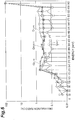
- Fig. 6 is a diagram illustrating one example of energy spectra of scattered radiation when the thickness of various shield members 3 was 1.0 millimeter.
- the graph G Au10 indicates an energy spectrum of scattered radiation when the shield member 3 was Au having a thickness of 1.0 millimeter.
- the graph G Al10 indicates an energy spectrum of scattered radiation when the shield member 3 was Al having a thickness of 1.0 millimeter.
- the graph G SUS10 indicates an energy spectrum of scattered radiation when the shield member 3 was stainless steel having a thickness of 1.0 millimeter.
- the graph G Cu10 indicates an energy spectrum of scattered radiation when the shield member 3 was Cu having a thickness of 1.0 millimeter.
- the energy spectra of these scattered radiations indicate energy spectra after radiations each having an energy of 662 keV were scattered by the respective shield members 3.
- the distribution ratio of energy near 662 keV was close to 100%
- the distribution ratio of energy of 200 keV to 660 keV was about 0.3 to 0.8%
- the distribution ratio of energy of 200 keV or less was about 0.02 to 0.1%
- the shield member 3 was Al having a thickness of 1.0 millimeter
- the distribution ratio of energy near 662 keV was close to 100%
- the distribution ratio of energy of 200 keV to 660 keV was about 0.08 to 0.3%
- the distribution ratio of energy of 200 keV or less was about 0.01 to 0.06%.
- the shield member 3 was stainless steel having a thickness of 1.0 millimeter, the distribution ratio of energy near 662 keV was close to 100%, the distribution ratio of energy of 200 keV to 660 keV was about 0.3 to 0.7%, the distribution ratio of energy of 200 keV or less was about 0 to 0.06%.
- the shield member 3 was Cu having a thickness of 1.0 millimeter, the distribution ratio of energy near 662 keV was close to 100%, the distribution ratio of energy of 200 keV to 660 keV was about 0.3 to 0.7%, the distribution ratio of energy of 200 keV or less was about 0 to 0.07%.
- Fig. 7 is a diagram illustrating one example of scattering rates of 662-keV radiation in the various shield members 3 of Figs. 4 to 6 . As depicted in Fig. 7 , it was found that the scattering rate increases as the thickness of the shield member 3 increases. It was also found that Au had the highest scattering rate among Au, Al, stainless steel, and Cu.
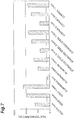
- Fig. 8 is a diagram illustrating increasing rates of radiation absorbed amount in the radiation detector 2. These increasing rates of radiation absorbed amount are increasing rates with respect to the radiation absorbed amount in the radiation detector 2 when the shield members 3 are not provided. As depicted in Fig. 8 , the increasing rate of radiation absorbed amount was the highest at 13.6% when the shield member 3 being Au having a thickness of 0.1 millimeter was used out of the various shield members 3 of Figs. 4 to 6 . Even when the other types of shield members 3 were used, increasing rates of the order of several percent were obtained. These increasing rates of radiation absorbed amount are determined based on the ratios between the rates of radiation scattered by the shield members 3 and the rate of radiation absorbed by the radiation detector 2. Thus, when a shield member 3 having a higher scattering rate and a radiation detector 2 having a higher absorptance in lower energy ranges are used, the increasing rate of radiation absorbed amount in the radiation detector 2 is also higher.
- the distribution ratio of energy near 662 keV was close to 100%, and the distribution ratio of energy of 660 keV or less was in the order of several percent.
- the radiation r1 having an energy of 662 keV enters the shield members 3 of Figs. 4 to 6 , the scattering itself occurs in the shield members 3 only to the extent of several percent, but the energy of the radiation r2 after the scattering is distributed at a certain percentage in energy ranges lower than 662 keV.
- the energy of the radiation r2 after the scattering is distributed at a certain percentage in energy ranges lower than 662 keV.
- the absorptance of 662-keV energy in the radiation detector 2 was about 0.7%, but the absorptance of 200-keV energy was about 3%, and the absorptance of 100-keV energy was about 15%.
- the absorptance improves by the order of several percent to ten-odd percent as a whole in comparison to the case without the shield member 3 provided.
- the radiation r2 scattered by the shield member 3 is detected by the radiation detector 2. Consequently, the absorptance of radiation in the radiation detector 2 improves, and the detection sensitivity of radiation improves.
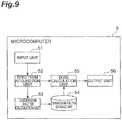
- Fig. 9 is a functional block diagram of the microcomputer 5. As depicted in Fig. 9 , the microcomputer 5 includes an input unit 51, a spectrum acquisition unit 52, a conversion-factor calculation unit 53, a conversion-factor storage unit 54, a dose calculation unit 55, and an output unit 56.
- the input unit 51 receives operation of a user via the operation button 6.
- the input unit 51 then examines the content of the received operation. For example, the input unit 51 determines whether the received operation is operation of selecting the initializing mode. In an explanation with a concrete example, when a screen for selecting operation modes is displayed on the display unit 7, the input unit 51 determines whether the operation of selecting the initializing mode is performed.
- the input unit 51 transmits operation information on the received operation to the spectrum acquisition unit 52 and the dose calculation unit 55. For example, the input unit 51 transmits information on the selected operation mode to the spectrum acquisition unit 52 and the dose calculation unit 55.
- the spectrum acquisition unit 52 acquires a channel spectrum of radiation detected by the radiation detector 2.
- the spectrum acquisition unit 52 receives a detection signal output from the amplifier 4 in response to, for example, the reception of the information on the operation mode from the input unit 51.
- the spectrum acquisition unit 52 measures the voltage value of the received detection signal, and counts the number of incidences using the voltage value (channel) as the abscissa in a histogram form to acquire the channel spectrum.
- the conversion-factor calculation unit 53 calculates a conversion factor for converting energy into a dose on the basis of the channel spectrum acquired by the spectrum acquisition unit 52.
- the conversion-factor calculation unit 53 analyzes the channel spectrum acquired by the spectrum acquisition unit 52 to search a peak of the channel spectrum.
- the conversion-factor calculation unit 53 then calculates a peak centroid channel.
- the sum total S all of weighted areas is calculated by summing the product of a count value C i for each channel Ch i and the channel Ch i from a peak start channel Ch a to a peak end channel Ch b .
- the peaks generally depend on Gaussian distribution. Accordingly, the peak start channel Ch a and the peak end channel Ch b are determined manually by visual measurement or automatically by an acquisition algorithm as points between which the whole Gaussian distribution fits.
- a and b each are an integer of one or more, and b is larger than a.
- the total count value C all is calculated by summing the count value C i for each channel Ch i from the peak start channel Ch a to the peak end channel Ch b .
- the conversion-factor calculation unit 53 calculates a first calibration factor A and a second calibration factor B for converting a channel Ch into an energy E.
- the relation between a first peak centroid channel Ch p1 and a predetermined first energy E 1 is represented by the following equation (4) using the first calibration factor A and the second calibration factor B.
- the relation between a second peak centroid channel Ch p2 and a predetermined second energy E 2 is represented by the following equation (5) using the first calibration factor A and the second calibration factor B.
- E 1 A ⁇ Ch p 1 + B
- E 2 A ⁇ Ch p 2 + B
- the first energy E 1 and the second energy E 2 each are a peak energy of a radioactive substance whose peak energy in the energy spectrum is known in advance.
- the first peak centroid channel Ch p1 is a peak centroid channel that is calculated from a measured channel spectrum of a radioactive substance having a peak energy of the first energy E 1 .
- the second peak centroid channel Ch p2 is a peak centroid channel that is calculated from a measured channel spectrum of a radioactive substance having a peak energy of the second energy E 2 .
- the first calibration factor A and the second calibration factor B are calculated by the following equations (6) and (7) that are obtained by solving the above-described simultaneous equations (4) and (5).
- the conversion-factor calculation unit 53 stores the first calibration factor A and the second calibration factor B in the conversion-factor storage unit 54.
- A E 2 ⁇ E 1 Ch p 2 ⁇ Ch p 1
- B E 2 ⁇ E 2 ⁇ E 1 Ch p 2 ⁇ Ch p 1 ⁇ Ch p 2
- the conversion-factor calculation unit 53 converts the channel Ch into the energy E.
- the conversion-factor calculation unit 53 converts each channel Ch j into an energy E j , thereby converting a channel spectrum acquired by the spectrum acquisition unit 52 into a histogram (energy spectrum) of the energy E versus the count value C. Furthermore, the conversion-factor calculation unit 53 adds up count values for each certain energy range (e.g., 100 keV) in the energy spectrum to convert the energy spectrum into spectra for a dozen or so points.
- certain energy range e.g. 100 keV
- the conversion-factor calculation unit 53 multiplies the added-up count values by a surveymeter factor corresponding to the energy of each point to calculate a conversion factor for each energy range.
- the surveymeter factor herein is a response function for a surveymeter corresponding to radiation energy, and is publicly available from surveymeter dealers. This surveymeter factor is determined in advance for each energy.
- the conversion-factor calculation unit 53 stores the conversion factor thus calculated in the conversion-factor storage unit 54.
- the conversion-factor storage unit 54 stores therein the first calibration factor A and the second calibration factor B calculated by the conversion-factor calculation unit 53 and the conversion factors for the respective energies calculated by the conversion-factor calculation unit 53.
- the dose calculation unit 55 calculates a dose on the basis of the channel spectrum acquired by the spectrum acquisition unit 52 and the first calibration factor A, the second calibration factor B, and the conversion factors stored in the conversion-factor storage unit 54.
- the dose calculation unit 55 uses the first calibration factor A and the second calibration factor B as represented by the above equation (8) to convert the channel spectrum into an energy spectrum.
- the dose calculation unit 55 adds up count values of the energy spectrum for each energy range that is the same as for the conversion factors to convert the energy spectrum into spectra for a dozen or so points.
- the dose calculation unit 55 multiplies the count value in each energy range by a conversion factor corresponding to the energy range to calculate a dose for each energy range.
- the dose calculation unit 55 then adds up the doses in the respective energy ranges to calculate the total dose.
- the output unit 56 outputs display information for displaying the dose calculated by the dose calculation unit 55 on the display unit 7.
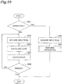
- Fig. 10 is a flowchart illustrating the operation of the radiation dosimeter 1. The operation of the radiation dosimeter 1 is started when a user operates the power supply switch 9 to switch the power supply 8 from the OFF state to the ON state.
- the input unit 51 determines whether the received operation is operation of selecting the initializing mode (step S01). At step S01, if it is determined that the received operation is operation of selecting the initializing mode (YES at step S01), an initializing process is performed.
- the spectrum acquisition unit 52 receives a detection signal output from the radiation detector 2 via the amplifier 4, and acquires a channel spectrum of radiation detected by the radiation detector 2 (step S02).
- the conversion-factor calculation unit 53 calculates a conversion factor on the basis of the channel spectrum acquired by the spectrum acquisition unit 52, and stores the calculated conversion factor in the conversion-factor storage unit 54 (step S03). Details of step S03 will be described later.
- the operation (initializing process) of the radiation dosimeter 1 ends.
- step S01 if it is determined that the received operation is not operation of selecting the initializing mode (NO at step S01), that is, if it is determined that the received operation is operation of selecting another operation mode, a radiation-dose calculation process based on the selected mode is performed.
- the spectrum acquisition unit 52 receives a detection signal output from the radiation detector 2 via the amplifier 4, and acquires a channel spectrum of radiation detected by the radiation detector 2 (step S05).
- the dose calculation unit 55 converts the channel spectrum acquired by the spectrum acquisition unit 52 into an energy spectrum on the basis of the first calibration factor A and the second calibration factor B stored in the conversion-factor storage unit 54 using the above equation (8) (spectrum acquisition step).
- the dose calculation unit 55 then calculates the dose of radiation on the basis of the energy spectrum thus converted and the conversion factors stored in the conversion-factor storage unit 54 (step S06, dose calculation step).
- the dose calculation unit 55 multiplies the count value for each energy of the energy spectrum by the conversion factor corresponding to the energy to calculate the dose for each energy.
- the dose calculation unit 55 then adds up the doses for the respective energies to calculate the total dose.
- the output unit 56 outputs display information for displaying the dose calculated by the dose calculation unit 55 on the display unit 7, thereby causing the display unit 7 to display the dose (step S07).
- the input unit 51 determines whether operation of ending the radiation-dose calculation process has been performed (step S08). Examples of the operation of ending the radiation-dose calculation process include operation of switching the power supply 8 to the OFF state with the power supply switch 9.
- step S08 if it is determined that the operation of ending the radiation-dose calculation process is not performed (NO at step S08), the flow returns to step S05, and the processes of step S05 to step S08 are repeated.
- step S08 if it is determined that the operation of ending the radiation-dose calculation process is performed (YES at step S08), the operation (radiation-dose calculation process) of the radiation dosimeter 1 ends.
- step S08 follows step S07. However, because the power supply switch 9 can be operated at any given timing by the user, step S08 may be performed for each predetermined period regardless of the flowchart in Fig. 10 .
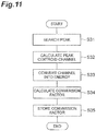
- Fig. 11 is a flowchart illustrating the details of the calibration process.
- the conversion-factor calculation unit 53 first analyzes the channel spectrum acquired by the spectrum acquisition unit 52 to search a peak of the channel spectrum (step S31).
- the conversion-factor calculation unit 53 then calculates a peak centroid channel using the above equations (1) to (3) (step S32).
- the conversion-factor calculation unit 53 calculates the first calibration factor A and the second calibration factor B for converting a channel into energy on the basis of the calculated peak centroid channel using the above equations (4) to (7).
- the conversion-factor calculation unit 53 then converts the channel spectrum into an energy spectrum using the above equation (8) (step S33).
- the conversion-factor calculation unit 53 adds up count values for each certain energy range (e.g., 100 keV) in the energy spectrum to convert the energy spectrum into spectra for a dozen or so points.
- the conversion-factor calculation unit 53 then multiplies the added-up count values by a surveymeter factor corresponding to the energy of each point to calculate a conversion factor for each energy range (step S34).
- the conversion-factor calculation unit 53 then stores the calculated conversion factor in the conversion-factor storage unit 54 (step S35), and ends the calibration process.
- the radiation detector 2 is covered by the shield member 3, whereby noise can be reduced and also the incident radiation r1 can be scattered.
- the energy of the radiation r2 after this scattering is distributed at a certain percentage in energy ranges lower than the energy of the radiation r1 before the scattering.
- the absorptance of radiation in energy ranges lower than the energy of the radiation r1 before the scattering is higher than the absorptance of radiation in the energy of the radiation r1 before the scattering.
- the detection sensitivity to radiation can be improved.
- the dose without the shield member 3 i.e., the net dose directly absorbed into a human body can be calculated. Consequently, the accuracy of dose measurement can be improved without complicating the structure.
- the radiation detector 2 may comprise cadmium zinc telluride (CdZnTe), thallium bromide (TlBr), or germanium (Ge), for example, because the absorptance in energy ranges lower than the energy of radiation to be detected before scattering only has to be higher than the absorptance in the energy of radiation before the scattering.
- CdZnTe cadmium zinc telluride
- TlBr thallium bromide
- Ge germanium
- the operation button 6 may be replaced with another input device.
- the input unit 51 may determine that the initializing mode has been selected by detecting that, with a certain button of the operation button 6 being pushed, the power supply switch 9 is pushed to switch the power supply 8 into the ON state.
- the conversion-factor calculation unit 53 calculates a conversion factor every 100 keV, but may calculate the conversion factor for each of any energy ranges. Smaller energy ranges enable the dose calculation unit 55 to calculate a more accurate dose.
- the conversion-factor calculation unit 53 may calculate a second conversion factor for converting a count value for each channel into a dose on the basis of the first calibration factor A, the second calibration factor B, and the conversion factors.
- the dose calculation unit 55 may calculate the dose by multiplying the count value for each channel of the channel spectrum acquired by the spectrum acquisition unit 52 by the second conversion factor.
Landscapes
- Physics & Mathematics (AREA)
- Health & Medical Sciences (AREA)
- Life Sciences & Earth Sciences (AREA)
- General Physics & Mathematics (AREA)
- High Energy & Nuclear Physics (AREA)
- Molecular Biology (AREA)
- Spectroscopy & Molecular Physics (AREA)
- Measurement Of Radiation (AREA)
Description
- The present invention relates to a radiation dosimeter and a radiation dose calculation method.
- A radiation dosimeter provided with a radiation detector using a semiconductor is available. In such a radiation dosimeter, detection sensitivity to radiation energy differs depending on the semiconductor used for the radiation detector. For example, in a radiation detector using a semiconductor such as CdTe, the detection sensitivity to radiation in a lower energy range is higher than the detection sensitivity to radiation in a higher energy range. Thus, the detection sensitivity and the dose measurement accuracy to higher energy radiation are required to be improved.
-
Patent Literature 1 describes a radiation detector including a semiconductor detector covered by an electromagnetic shield, which serves as a radiation absorbing filter that absorbs a certain amount of radiation in a low energy range, to improve the uniformity of detection sensitivity to energy, and a scintillator layer and a reflection layer provided on a surface opposite to the incidence surface of the semiconductor detector. In this radiation detector, the scintillator layer emits light due to high-energy radiation passing through the semiconductor detector, and the emitted light is reflected by the reflection layer and is detected by the semiconductor detector. -
US4859853 discloses a solid state gamma ray dosimeter which measures radiation in terms of absorption in a material different from the detector material. A solid state detector, an amplifier, an analog-to-digital interface and a microprocessor are combined in circuit to correct for differences between absorption of radiation in detector material and absorption in other materials, especially tissue. A suitable cladding may surround the detector. A method of generating dose translation data for calibrating the microprocessor is also disclosed. The solid state detector is attached to a multichannel analyzer circuit and subject to known doses of various monochromatic gamma rays. Output pulses from the detector are amplified and introduced into the multichannel analyzer. The spectrum produced is used to determine an average channel number (or pulse height) for a given dose of monochromatic radiation. The given dose is in units specific to material different from the detector material. The partial dose represented by a single detector pulse at that energy is computed. Partial doses for other energies are likewise computed. Dose translation data associates a partial dose with a given detector pulse height. Dose translation data is set in the microprocessor of the dosimeter. Such dose translation data can be used to calculate total dose and dose rate in units peculiar to material other than detector material. -
US2011051901 relates to a device and method for determining one or more characteristics of radiation using a sensor comprising one or more detector units capable of counting the number of photon or charged particle of said radiation impinging on said sensor in or above a determined energy range. -
US4461952 relates to a portable computing device comprising, in known manner, means for adding digital information, means for determining periods of time and display means, wherein it also comprises a nuclear detector adapted to deliver electrical signals whose amplitude spectrum depends biunivocally on the energy spectrum of the radiation in which it is placed and means for converting these signals into digital information, the addition means receiving said digital information, the means for determining periods of time controlling said addition means so as to make a calculation of the dose of nuclear radiation received during a period of time, called integral dose, which is displayed by said display means. The invention is more particularly applicable in the domain of protection against radiation, or health physics. - "Solid-state personal dosimeter using dose conversion algorithm" by Lee B. J. et al. relates to the design and testing of a personal dosimeter based on a silicon PIN photodiode.
- [Patent Literature 1] Japanese Patent Application Laid-Open Publication No.
2001-4754 - However, the radiation detector described in
Patent Literature 1 needs to include the scintillator layer and the reflection layer to improve the detection sensitivity to radiation in a high energy range and the accuracy of dose measurement. Accordingly, the structure becomes more complicated and the device becomes larger. - According to one embodiment of the present invention, a radiation dosimeter and a radiation dose calculation method are provided that enable the accuracy of dose measurement to be improved with a simple structure.
- A radiation dosimeter according to
claim 1 is provided. - With this radiation dosimeter, noise can be reduced and also incident radiation can be scattered by covering the radiation detector with the shield member. The energy of this scattered radiation is distributed at a certain percentage in an energy range lower than the energy of radiation before being scattered. Thus, the detection sensitivity to radiation can be improved when using a radiation detector with which the absorptance (detection sensitivity) in an energy range lower than the energy of radiation before being scattered is higher than the absorptance in the energy of radiation before being scattered. By calculating the dose from the energy of the detected radiation with the conversion factor defined in accordance with the energy of radiation scattered by the shield member, the dose when the shield member does not exist, i.e., the net dose directly absorbed into a human body, can be calculated. Consequently, the accuracy of dose measurement can be improved without complicating the structure.
- The radiation detector may comprise CdTe. The CdTe semiconductor has a high efficiency of absorbing radiation. This high efficiency can further improve the detection sensitivity to radiation and can further improve the accuracy of dose measurement.
- The shield member also may have a thickness of 0.1 millimeter or more and 1.0 millimeter or less. When such a shield member covers the radiation detector, the detection sensitivity to radiation can be improved and the accuracy of dose measurement can be improved.
- The radiation dosimeter may further include a display unit that displays the dose calculated by the arithmetic unit. In this case, displaying an accurately measured dose on the display unit can let a user know more accurate dose.
- A radiation dose calculation method according to
claim 5 is provided. - In this radiation dose calculation method, incident radiation is scattered by the shield member covering the radiation detector. The energy spectrum of this scattered radiation is distributed at a certain percentage in an energy range lower than the energy of radiation before being scattered. Thus, the detection sensitivity to radiation can be improved when using a radiation detector with which the absorptance in an energy range lower than the energy of radiation before being scattered is higher than the absorptance in the energy of radiation before being scattered. By calculating the dose on the basis of the energy spectrum of radiation detected by the radiation detector in this manner, the accuracy of dose measurement can be improved without complicating the structure. Furthermore, by calculating the dose from the energy spectrum of the detected radiation with the conversion factor defined in accordance with the energy of radiation scattered by the shield member, the dose when the shield member does not exist, i.e., the net dose directly absorbed into a human body, can be calculated.
- The present invention can improve the dose measurement accuracy.
-
- [
Fig. 1] Fig. 1 is a schematic block diagram of a radiation dosimeter according to a present embodiment. - [
Fig. 2] Fig. 2 is a diagram illustrating one example of energy response of the radiation detector inFig. 1 . - [
Fig. 3] Fig. 3 is a diagram illustrating a principle of detecting radiation in the radiation dosimeter inFig. 1 . - [
Fig. 4] Fig. 4 is a diagram illustrating one example of energy spectra of scattered radiation when the thickness of a shield member is 0.1 millimeter. - [
Fig. 5] Fig. 5 is a diagram illustrating one example of energy spectra of scattered radiation when the thickness of a shield member is 0.5 millimeter. - [
Fig. 6] Fig. 6 is a diagram illustrating one example of energy spectra of scattered radiation when the thickness of a shield member is 1.0 millimeter. - [
Fig. 7] Fig. 7 is a diagram illustrating scattering rates of 662-keV radiation in various shield members. - [
Fig. 8] Fig. 8 is a diagram illustrating increasing rates of absorbed amount in the radiation detector inFig. 1 . - [
Fig. 9] Fig. 9 is a functional block diagram of the microcomputer inFig. 1 . - [
Fig. 10] Fig. 10 is a flowchart illustrating operation of the radiation dosimeter inFig. 1 . - [
Fig. 11] Fig. 11 is a flowchart illustrating details of the calibration process inFig. 10 . - Embodiments of the present invention will be described in detail with reference to the attached drawings. In descriptions of the drawings, the same or the corresponding parts are assigned with the same reference signs, and the redundant description will be omitted.
-
Fig. 1 is a schematic block diagram of a radiation dosimeter according to a present embodiment. As depicted inFig. 1 , thisradiation dosimeter 1 is a device that measures a radiation dose, and includes aradiation detector 2, ashield member 3, an amplifier 4, a microcomputer 5 (arithmetic unit), anoperation button 6, adisplay unit 7, apower supply 8, and apower supply switch 9. As a dose to be measured, a sievert (Sv) value, for example, is used. - The
radiation detector 2 is a detector made of a semiconductor that can detect radiation, and comprises cadmium telluride (CdTe), for example. The thickness of theradiation detector 2 is about 1 millimeter, for example. In theradiation detector 2, one surface and the other surface of the semiconductor that can detect radiation are provided with respective electrodes (not depicted). In theradiation detector 2, when energy of incident radiation is absorbed, an electron and a hole are generated depending on the magnitude of the energy. Subsequently, theradiation detector 2 outputs a detection signal having a voltage value depending on the magnitude of the energy to themicrocomputer 5 via the amplifier 4. -
Fig. 2 is a diagram illustrating one example of energy response of theradiation detector 2. The energy response herein means a relation between the energy of radiation and the absorptance of radiation, and is also referred to as a response function. InFig. 2 , the abscissa represents the energy of radiation and the ordinate represents the absorptance of radiation. In this example, theradiation detector 2 comprise CdTe, and the thickness thereof is 1 millimeter. As depicted inFig. 2 , the absorptance of radiation in lower energy ranges is higher than the absorptance of radiation in higher energy ranges, and the absorptance of radiation increases as the energy of radiation decreases. For example, it is known that cesium 137 emits a gamma ray having an energy of 662 keV. When theradiation detector 2 in this example is used alone, because the absorptance of gamma rays emitted from cesium 137 is about 0.7%, the detection sensitivity thereto is significantly low. - The
shield member 3 is a metallic sheet-like member, and comprises any of gold (Au), and stainless steel. Theshield member 3 has a thickness of 0.1 millimeter or more, for example, and has a thickness of 1.0 millimeter or less, for example. Theshield member 3 is provided so as to cover a surface of theradiation detector 2. Between theshield member 3 and theradiation detector 2, a gap of about 0.1 millimeter to 1 millimeter is provided. The amplifier 4 is a signal amplifier (preamplifier) that amplifies a detection signal output from theradiation detector 2. The amplifier 4 outputs the amplified detection signal to themicrocomputer 5. - The
microcomputer 5 is an arithmetic unit that calculates a dose on the basis of radiation detected by theradiation detector 2. Themicrocomputer 5 receives a detection signal amplified by the amplifier 4, and generates an energy spectrum depending on the voltage value of the detection signal received. Themicrocomputer 5 also performs a certain computation on the energy spectrum to calculate a radiation dose. Themicrocomputer 5 then outputs display information on the calculated dose to be displayed on thedisplay unit 7. - The
microcomputer 5 has anADC 5a. TheADC 5a converts the voltage value of the received detection signal into a channel. The channel herein means a memory address that corresponds to the magnitude of energy. In general, an energy spectrum represents a relation between energy and the strength of the energy, and the strength of energy is represented by a count value that is the number of incidences of radiation having the energy. Inside themicrocomputer 5, to save the capacity of a memory, count values of respective energies are stored in sequential addresses (channels) of the memory. More specifically, every time themicrocomputer 5 receives a detection signal from theradiation detector 2 via the amplifier 4, themicrocomputer 5 converts the voltage value of the detection signal into a channel with theADC 5a and increments the count value stored in the converted channel by one. In this manner, themicrocomputer 5 acquires a channel spectrum. Themicrocomputer 5 then converts the channel into energy for display, for example, to convert the channel spectrum into an energy spectrum. Details of functions of themicrocomputer 5 will be described later. - The
operation button 6 is an input device for operating theradiation dosimeter 1. Theoperation button 6 includes, for example, an operation button for selecting operation modes (accumulation mode, real-time mode) of theradiation dosimeter 1 and an operation button for providing instructions for determination. Examples of the operation modes of theradiation dosimeter 1 include an initializing mode, an accumulation mode, and a real-time mode. The initializing mode is an operation mode for initializing a conversion factor to calibrate the detection sensitivity of theradiation dosimeter 1. The initializing mode is activated by, for example, operation of selecting the initializing mode among the operation modes displayed on thedisplay unit 7, and operation of pushing down thepower supply switch 9 while pushing a certain button of theoperation button 6 to start up theradiation dosimeter 1. This process of initializing the conversion factor in the initializing mode is performed by a manufacturer or a dealer at shipment of the product, for example. - The accumulation mode is a mode for displaying a radiation dose (Sv) measured during a period from a power-ON state to a power-OFF state. The real-time mode is a mode for displaying a radiation dose rate (Sv/h) measured in the power-ON state.
- The
display unit 7 is a display unit such as a liquid crystal display. Thisdisplay unit 7 displays predetermined information on the basis of the display information output by themicrocomputer 5. For example, thedisplay unit 7 displays the dose calculated by themicrocomputer 5 and the state of thepower supply 8. Thepower supply 8 supplies power to each component of theradiation dosimeter 1. Thepower supply 8 can be switched between the ON state and the OFF state by operating thepower supply switch 9. - The following describes a principle of detecting radiation in the
radiation dosimeter 1 with reference toFig. 3. Fig. 3 is a diagram illustrating a cross section of theradiation detector 2 and theshield member 3. As depicted inFig. 3 , theradiation detector 2 is covered by theshield member 3. In theradiation dosimeter 1, when a radiation r1 in the atmosphere enters theshield member 3, Compton scattering occurs in theshield member 3. At this time, the energy of a radiation r2 after the scattering is equal to or lower than the energy of the radiation r1, and is distributed at a certain percentage in energy ranges lower than the energy of the radiation r1 before the scattering. Part of the radiation r2 after the scattering is absorbed by theradiation detector 2. The radiation r2 passing through theradiation detector 2 without being absorbed passes through theshield member 3 to exit to the outside. - As described above, in the
radiation detector 2, the absorptance of radiation in lower energy ranges is higher than the absorptance of radiation in higher energy ranges. Thus, in theradiation detector 2, the absorptance of the radiation r2 is higher than the absorptance of the radiation r1. Consequently, the absorptance of radiation in theradiation detector 2 improves, and the detection sensitivity to radiation improves. - The following describes concrete examples of radiation detection in the
radiation dosimeter 1 with reference toFigs. 4 to 8 . In these examples, stainless steel contained 1% of silicon (Si), 18% of chrome (Cr), 2% of manganese (Mn), 70% of iron (Fe), and 9% of nickel (Ni), and the density of the stainless steel was 7.93 g/cm3. In these examples, theradiation detector 2 comprised CdTe, and the thickness thereof was 1 millimeter. Between theradiation detector 2 and theshield member 3, a gap of about 0.1 millimeter to 1.0 millimeter was provided. -
Fig. 4 is a diagram illustrating one example of energy spectra of scattered radiation when the thickness of various shield members 3 (Au, Al, stainless steel, and Cu) was 0.1 millimeter. InFig. 4 , the abscissa represents the energy of radiation incident into theradiation detector 2, and the ordinate represents the ratio (distribution ratio) of the number of incidences of radiation for each energy to the total number of incidences of radiation. The same applies toFigs. 5 and6 . The graph GAu01 indicates an energy spectrum of scattered radiation when theshield member 3 was Au having a thickness of 0.1 millimeter. The graph GAl101 indicates an energy spectrum of scattered radiation when theshield member 3 was Al having a thickness of 0.1 millimeter. The graph GSUS01 indicates an energy spectrum of scattered radiation when theshield member 3 was stainless steel having a thickness of 0.1 millimeter. The graph GCu01 indicates an energy spectrum of scattered radiation when theshield member 3 was Cu having a thickness of 0.1 millimeter. The energy spectra of these scattered radiations indicate energy spectra after radiations each having an energy of 662 keV were scattered by therespective shield members 3. - As depicted in
Fig. 4 , when theshield member 3 was Au having a thickness of 0.1 millimeter, the distribution ratio of energy near 662 keV was close to 100%, the distribution ratio of energy of 200 keV to 660 keV was about 0.1%, the distribution ratio of energy of 200 keV or less was about 0.01 to 0.08%. When theshield member 3 was Al having a thickness of 0.1 millimeter, the distribution ratio of energy near 662 keV was close to 100%, the distribution ratio of energy of 660 keV or less was about 0 to 0.05%. When theshield member 3 was stainless steel having a thickness of 0.1 millimeter, the distribution ratio of energy near 662 keV was close to 100%, the distribution ratio of energy of 200 keV to 660 keV was about 0.04 to 0.09%, the distribution ratio of energy of 200 keV or less was about 0.01 to 0.02%. When theshield member 3 was Cu having a thickness of 0.1 millimeter, the distribution ratio of energy near 662 keV was close to 100%, the distribution ratio of energy of 200 keV to 660 keV was about 0.04 to 0.09%, the distribution ratio of energy of 200 keV or less was about 0.01 to 0.04%. -
Fig. 5 is a diagram illustrating one example of energy spectra of scattered radiation when the thickness ofvarious shield members 3 was 0.5 millimeter. The graph GAu05 indicates an energy spectrum of scattered radiation when theshield member 3 was Au having a thickness of 0.5 millimeter. The graph GAl05 indicates an energy spectrum of scattered radiation when theshield member 3 was Al having a thickness of 0.5 millimeter. The graph GSUS05 indicates an energy spectrum of scattered radiation when theshield member 3 was stainless steel having a thickness of 0.5 millimeter. The graph GCu05 indicates an energy spectrum of scattered radiation when theshield member 3 was Cu having a thickness of 0.5 millimeter. The energy spectra of these scattered radiations indicate energy spectra after radiations each having an energy of 662 keV were scattered by therespective shield members 3. - As depicted in
Fig. 5 , when theshield member 3 was Au having a thickness of 0.5 millimeter, the distribution ratio of energy near 662 keV was close to 100%, the distribution ratio of energy of 200 keV to 660 keV was about 0.2 to 0.6%, the distribution ratio of energy of 200 keV or less was about 0.01 to 0.08%. When theshield member 3 was Al having a thickness of 0.5 millimeter, the distribution ratio of energy near 662 keV was close to 100%, the distribution ratio of energy of 200 keV to 660 keV was about 0.04 to 0.1%, the distribution ratio of energy of 200 keV or less was about 0 to 0.03%. When theshield member 3 was stainless steel having a thickness of 0.5 millimeter, the distribution ratio of energy near 662 keV was close to 100%, the distribution ratio of energy of 200 keV to 660 keV was about 0.1 to 0.3%, the distribution ratio of energy of 200 keV or less was about 0.02 to 0.05%. When theshield member 3 was Cu having a thickness of 0.5 millimeter, the distribution ratio of energy near 662 keV was close to 100%, the distribution ratio of energy of 200 keV to 660 keV was about 0.1 to 0.3%, the distribution ratio of energy of 200 keV or less was about 0 to 0.1%. -
Fig. 6 is a diagram illustrating one example of energy spectra of scattered radiation when the thickness ofvarious shield members 3 was 1.0 millimeter. The graph GAu10 indicates an energy spectrum of scattered radiation when theshield member 3 was Au having a thickness of 1.0 millimeter. The graph GAl10 indicates an energy spectrum of scattered radiation when theshield member 3 was Al having a thickness of 1.0 millimeter. The graph GSUS10 indicates an energy spectrum of scattered radiation when theshield member 3 was stainless steel having a thickness of 1.0 millimeter. The graph GCu10 indicates an energy spectrum of scattered radiation when theshield member 3 was Cu having a thickness of 1.0 millimeter. The energy spectra of these scattered radiations indicate energy spectra after radiations each having an energy of 662 keV were scattered by therespective shield members 3. - As depicted in
Fig. 6 , when theshield member 3 was Au having a thickness of 1.0 millimeter, the distribution ratio of energy near 662 keV was close to 100%, the distribution ratio of energy of 200 keV to 660 keV was about 0.3 to 0.8%, the distribution ratio of energy of 200 keV or less was about 0.02 to 0.1%. When theshield member 3 was Al having a thickness of 1.0 millimeter, the distribution ratio of energy near 662 keV was close to 100%, the distribution ratio of energy of 200 keV to 660 keV was about 0.08 to 0.3%, the distribution ratio of energy of 200 keV or less was about 0.01 to 0.06%. When theshield member 3 was stainless steel having a thickness of 1.0 millimeter, the distribution ratio of energy near 662 keV was close to 100%, the distribution ratio of energy of 200 keV to 660 keV was about 0.3 to 0.7%, the distribution ratio of energy of 200 keV or less was about 0 to 0.06%. When theshield member 3 was Cu having a thickness of 1.0 millimeter, the distribution ratio of energy near 662 keV was close to 100%, the distribution ratio of energy of 200 keV to 660 keV was about 0.3 to 0.7%, the distribution ratio of energy of 200 keV or less was about 0 to 0.07%. -
Fig. 7 is a diagram illustrating one example of scattering rates of 662-keV radiation in thevarious shield members 3 ofFigs. 4 to 6 . As depicted inFig. 7 , it was found that the scattering rate increases as the thickness of theshield member 3 increases. It was also found that Au had the highest scattering rate among Au, Al, stainless steel, and Cu. -
Fig. 8 is a diagram illustrating increasing rates of radiation absorbed amount in theradiation detector 2. These increasing rates of radiation absorbed amount are increasing rates with respect to the radiation absorbed amount in theradiation detector 2 when theshield members 3 are not provided. As depicted inFig. 8 , the increasing rate of radiation absorbed amount was the highest at 13.6% when theshield member 3 being Au having a thickness of 0.1 millimeter was used out of thevarious shield members 3 ofFigs. 4 to 6 . Even when the other types ofshield members 3 were used, increasing rates of the order of several percent were obtained. These increasing rates of radiation absorbed amount are determined based on the ratios between the rates of radiation scattered by theshield members 3 and the rate of radiation absorbed by theradiation detector 2. Thus, when ashield member 3 having a higher scattering rate and aradiation detector 2 having a higher absorptance in lower energy ranges are used, the increasing rate of radiation absorbed amount in theradiation detector 2 is also higher. - As described above, whichever metal in
Figs. 4 to 6 was used, the distribution ratio of energy near 662 keV was close to 100%, and the distribution ratio of energy of 660 keV or less was in the order of several percent. Thus, if the radiation r1 having an energy of 662 keV enters theshield members 3 ofFigs. 4 to 6 , the scattering itself occurs in theshield members 3 only to the extent of several percent, but the energy of the radiation r2 after the scattering is distributed at a certain percentage in energy ranges lower than 662 keV. In contrast, as depicted inFig. 2 , the absorptance of 662-keV energy in theradiation detector 2 was about 0.7%, but the absorptance of 200-keV energy was about 3%, and the absorptance of 100-keV energy was about 15%. In this manner, in theradiation detector 2, because the absorptance of the radiation r2 of lower energy after the scattering is higher than the absorptance of the radiation r1 before the scattering, the absorptance (detection sensitivity) improves by the order of several percent to ten-odd percent as a whole in comparison to the case without theshield member 3 provided. - As described above, the radiation r2 scattered by the
shield member 3 is detected by theradiation detector 2. Consequently, the absorptance of radiation in theradiation detector 2 improves, and the detection sensitivity of radiation improves. - The following describes a method of calculating the dose of radiation detected as described above. This calculation of the dose is performed by the
microcomputer 5.Fig. 9 is a functional block diagram of themicrocomputer 5. As depicted inFig. 9 , themicrocomputer 5 includes aninput unit 51, aspectrum acquisition unit 52, a conversion-factor calculation unit 53, a conversion-factor storage unit 54, adose calculation unit 55, and anoutput unit 56. - The
input unit 51 receives operation of a user via theoperation button 6. Theinput unit 51 then examines the content of the received operation. For example, theinput unit 51 determines whether the received operation is operation of selecting the initializing mode. In an explanation with a concrete example, when a screen for selecting operation modes is displayed on thedisplay unit 7, theinput unit 51 determines whether the operation of selecting the initializing mode is performed. Theinput unit 51 then transmits operation information on the received operation to thespectrum acquisition unit 52 and thedose calculation unit 55. For example, theinput unit 51 transmits information on the selected operation mode to thespectrum acquisition unit 52 and thedose calculation unit 55. - The
spectrum acquisition unit 52 acquires a channel spectrum of radiation detected by theradiation detector 2. Thespectrum acquisition unit 52 receives a detection signal output from the amplifier 4 in response to, for example, the reception of the information on the operation mode from theinput unit 51. Thespectrum acquisition unit 52 then measures the voltage value of the received detection signal, and counts the number of incidences using the voltage value (channel) as the abscissa in a histogram form to acquire the channel spectrum. - The conversion-
factor calculation unit 53 calculates a conversion factor for converting energy into a dose on the basis of the channel spectrum acquired by thespectrum acquisition unit 52. The following describes in detail a method of calculating the conversion factor from the channel spectrum. To begin with, the conversion-factor calculation unit 53 analyzes the channel spectrum acquired by thespectrum acquisition unit 52 to search a peak of the channel spectrum. The conversion-factor calculation unit 53 then calculates a peak centroid channel. This peak centroid channel Chp herein is a channel corresponding to the center point of the peak, and is calculated by the following equation (1) using a sum total Sall of weighted areas and a total count value Call.
[Numeral 1]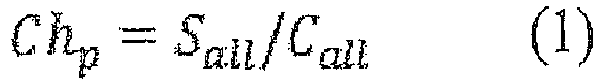
- As represented by the following equation (2), the sum total Sall of weighted areas is calculated by summing the product of a count value Ci for each channel Chi and the channel Chi from a peak start channel Cha to a peak end channel Chb. The peaks generally depend on Gaussian distribution. Accordingly, the peak start channel Cha and the peak end channel Chb are determined manually by visual measurement or automatically by an acquisition algorithm as points between which the whole Gaussian distribution fits. Herein, a and b each are an integer of one or more, and b is larger than a.
[Numeral 2]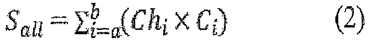
- As represented by the following equation (3), the total count value Call is calculated by summing the count value Ci for each channel Chi from the peak start channel Cha to the peak end channel Chb.
[Numeral 3]
- Subsequently, the conversion-
factor calculation unit 53 calculates a first calibration factor A and a second calibration factor B for converting a channel Ch into an energy E. Herein, the relation between a first peak centroid channel Chp1 and a predetermined first energy E1 is represented by the following equation (4) using the first calibration factor A and the second calibration factor B. Similarly, the relation between a second peak centroid channel Chp2 and a predetermined second energy E2 is represented by the following equation (5) using the first calibration factor A and the second calibration factor B.
[Numeral 4]

- The first energy E1 and the second energy E2 each are a peak energy of a radioactive substance whose peak energy in the energy spectrum is known in advance. The first peak centroid channel Chp1 is a peak centroid channel that is calculated from a measured channel spectrum of a radioactive substance having a peak energy of the first energy E1. Similarly, the second peak centroid channel Chp2 is a peak centroid channel that is calculated from a measured channel spectrum of a radioactive substance having a peak energy of the second energy E2.
- The first calibration factor A and the second calibration factor B are calculated by the following equations (6) and (7) that are obtained by solving the above-described simultaneous equations (4) and (5). The conversion-
factor calculation unit 53 stores the first calibration factor A and the second calibration factor B in the conversion-factor storage unit 54.
[Numeral 6]

- Subsequently, the conversion-
factor calculation unit 53 converts the channel Ch into the energy E. The energy Ej herein is calculated by the following equation (8) using the channel Chj, the first calibration factor A, and the second calibration factor B.
[Numeral 8]
- The conversion-
factor calculation unit 53 converts each channel Chj into an energy Ej, thereby converting a channel spectrum acquired by thespectrum acquisition unit 52 into a histogram (energy spectrum) of the energy E versus the count value C. Furthermore, the conversion-factor calculation unit 53 adds up count values for each certain energy range (e.g., 100 keV) in the energy spectrum to convert the energy spectrum into spectra for a dozen or so points. - The conversion-
factor calculation unit 53 multiplies the added-up count values by a surveymeter factor corresponding to the energy of each point to calculate a conversion factor for each energy range. The surveymeter factor herein is a response function for a surveymeter corresponding to radiation energy, and is publicly available from surveymeter dealers. This surveymeter factor is determined in advance for each energy. The conversion-factor calculation unit 53 stores the conversion factor thus calculated in the conversion-factor storage unit 54. - The conversion-
factor storage unit 54 stores therein the first calibration factor A and the second calibration factor B calculated by the conversion-factor calculation unit 53 and the conversion factors for the respective energies calculated by the conversion-factor calculation unit 53. - The
dose calculation unit 55 calculates a dose on the basis of the channel spectrum acquired by thespectrum acquisition unit 52 and the first calibration factor A, the second calibration factor B, and the conversion factors stored in the conversion-factor storage unit 54. In a more specific explanation, thedose calculation unit 55 uses the first calibration factor A and the second calibration factor B as represented by the above equation (8) to convert the channel spectrum into an energy spectrum. Furthermore, thedose calculation unit 55 adds up count values of the energy spectrum for each energy range that is the same as for the conversion factors to convert the energy spectrum into spectra for a dozen or so points. - The
dose calculation unit 55 multiplies the count value in each energy range by a conversion factor corresponding to the energy range to calculate a dose for each energy range. Thedose calculation unit 55 then adds up the doses in the respective energy ranges to calculate the total dose. Theoutput unit 56 outputs display information for displaying the dose calculated by thedose calculation unit 55 on thedisplay unit 7. - The following describes operation of the
radiation dosimeter 1 having the above-described configuration.Fig. 10 is a flowchart illustrating the operation of theradiation dosimeter 1. The operation of theradiation dosimeter 1 is started when a user operates thepower supply switch 9 to switch thepower supply 8 from the OFF state to the ON state. - To begin with, the
input unit 51 determines whether the received operation is operation of selecting the initializing mode (step S01). At step S01, if it is determined that the received operation is operation of selecting the initializing mode (YES at step S01), an initializing process is performed. In this initializing process, thespectrum acquisition unit 52 receives a detection signal output from theradiation detector 2 via the amplifier 4, and acquires a channel spectrum of radiation detected by the radiation detector 2 (step S02). Next, the conversion-factor calculation unit 53 calculates a conversion factor on the basis of the channel spectrum acquired by thespectrum acquisition unit 52, and stores the calculated conversion factor in the conversion-factor storage unit 54 (step S03). Details of step S03 will be described later. When the process of step S03 has been completed, the operation (initializing process) of theradiation dosimeter 1 ends. - At step S01, if it is determined that the received operation is not operation of selecting the initializing mode (NO at step S01), that is, if it is determined that the received operation is operation of selecting another operation mode, a radiation-dose calculation process based on the selected mode is performed. In this radiation-dose calculation process, the
spectrum acquisition unit 52 receives a detection signal output from theradiation detector 2 via the amplifier 4, and acquires a channel spectrum of radiation detected by the radiation detector 2 (step S05). - Next, the
dose calculation unit 55 converts the channel spectrum acquired by thespectrum acquisition unit 52 into an energy spectrum on the basis of the first calibration factor A and the second calibration factor B stored in the conversion-factor storage unit 54 using the above equation (8) (spectrum acquisition step). Thedose calculation unit 55 then calculates the dose of radiation on the basis of the energy spectrum thus converted and the conversion factors stored in the conversion-factor storage unit 54 (step S06, dose calculation step). In other words, thedose calculation unit 55 multiplies the count value for each energy of the energy spectrum by the conversion factor corresponding to the energy to calculate the dose for each energy. Thedose calculation unit 55 then adds up the doses for the respective energies to calculate the total dose. - The
output unit 56 outputs display information for displaying the dose calculated by thedose calculation unit 55 on thedisplay unit 7, thereby causing thedisplay unit 7 to display the dose (step S07). Subsequently, theinput unit 51 determines whether operation of ending the radiation-dose calculation process has been performed (step S08). Examples of the operation of ending the radiation-dose calculation process include operation of switching thepower supply 8 to the OFF state with thepower supply switch 9. At step S08, if it is determined that the operation of ending the radiation-dose calculation process is not performed (NO at step S08), the flow returns to step S05, and the processes of step S05 to step S08 are repeated. - At step S08, if it is determined that the operation of ending the radiation-dose calculation process is performed (YES at step S08), the operation (radiation-dose calculation process) of the
radiation dosimeter 1 ends. Herein, for convenience of explanation, step S08 follows step S07. However, because thepower supply switch 9 can be operated at any given timing by the user, step S08 may be performed for each predetermined period regardless of the flowchart inFig. 10 . - The following describes details of the calibration process at step S03.
Fig. 11 is a flowchart illustrating the details of the calibration process. As depicted inFig. 11 , the conversion-factor calculation unit 53 first analyzes the channel spectrum acquired by thespectrum acquisition unit 52 to search a peak of the channel spectrum (step S31). The conversion-factor calculation unit 53 then calculates a peak centroid channel using the above equations (1) to (3) (step S32). - Next, the conversion-
factor calculation unit 53 calculates the first calibration factor A and the second calibration factor B for converting a channel into energy on the basis of the calculated peak centroid channel using the above equations (4) to (7). The conversion-factor calculation unit 53 then converts the channel spectrum into an energy spectrum using the above equation (8) (step S33). - Subsequently, the conversion-
factor calculation unit 53 adds up count values for each certain energy range (e.g., 100 keV) in the energy spectrum to convert the energy spectrum into spectra for a dozen or so points. The conversion-factor calculation unit 53 then multiplies the added-up count values by a surveymeter factor corresponding to the energy of each point to calculate a conversion factor for each energy range (step S34). The conversion-factor calculation unit 53 then stores the calculated conversion factor in the conversion-factor storage unit 54 (step S35), and ends the calibration process. - In the
radiation dosimeter 1 and the radiation dose calculation method using theradiation dosimeter 1, theradiation detector 2 is covered by theshield member 3, whereby noise can be reduced and also the incident radiation r1 can be scattered. The energy of the radiation r2 after this scattering is distributed at a certain percentage in energy ranges lower than the energy of the radiation r1 before the scattering. In theradiation detector 2, the absorptance of radiation in energy ranges lower than the energy of the radiation r1 before the scattering is higher than the absorptance of radiation in the energy of the radiation r1 before the scattering. Thus, the detection sensitivity to radiation can be improved. - By using a conversion factor that is determined based on the energy of radiation scattered by the
shield member 3 to calculate the dose from the energy of detected radiation, the dose without theshield member 3, i.e., the net dose directly absorbed into a human body can be calculated. Consequently, the accuracy of dose measurement can be improved without complicating the structure. - It should be noted that the radiation dosimeter and the radiation dose calculation method according to the present invention are not limited to those described in the present embodiment. For example, the
radiation detector 2 may comprise cadmium zinc telluride (CdZnTe), thallium bromide (TlBr), or germanium (Ge), for example, because the absorptance in energy ranges lower than the energy of radiation to be detected before scattering only has to be higher than the absorptance in the energy of radiation before the scattering. - The
operation button 6 may be replaced with another input device. Theinput unit 51 may determine that the initializing mode has been selected by detecting that, with a certain button of theoperation button 6 being pushed, thepower supply switch 9 is pushed to switch thepower supply 8 into the ON state. - The conversion-
factor calculation unit 53 calculates a conversion factor every 100 keV, but may calculate the conversion factor for each of any energy ranges. Smaller energy ranges enable thedose calculation unit 55 to calculate a more accurate dose. - The conversion-
factor calculation unit 53 may calculate a second conversion factor for converting a count value for each channel into a dose on the basis of the first calibration factor A, the second calibration factor B, and the conversion factors. In this case, thedose calculation unit 55 may calculate the dose by multiplying the count value for each channel of the channel spectrum acquired by thespectrum acquisition unit 52 by the second conversion factor. - 1... radiation dosimeter, 2... radiation detector, 3... shield member, 5... microcomputer (arithmetic unit), 7... display unit
Claims (5)
- A radiation dosimeter (1) comprising:a radiation detector (2) made of a semiconductor that is configured to detect radiation;a shield member (3) that covers the radiation detector (2); andan arithmetic unit that is configured to calculate a dose of radiation based on energy of radiation detected by the radiation detector (2) and a conversion factor that is defined in accordance with energy of radiation scattered by the shield member (3),wherein the radiation detector (2) is configured to detect the radiation scattered by the shield member (3),characterised in that the shield member (3) comprises any of Au and stainless steel.
- The radiation dosimeter according to claim 1, wherein the radiation detector comprises CdTe.
- The radiation dosimeter according to claim 1 or 2, wherein the shield member has a thickness of 0.1 millimeter or more and 1.0 millimeter or less.
- The radiation dosimeter according to any one of claims 1 to 3, wherein the radiation dosimeter further comprises a display unit that is configured to display the dose calculated by the arithmetic unit.
- A radiation dose calculation method using the radiation dosimeter of any one of claims 1 to 4, characterised in that the radiation dose calculation method comprises:a spectrum acquisition step of acquiring an energy spectrum of radiation that is detected by the radiation detector (2) after being scattered by the shield member (3);a dose calculation step of calculating a radiation dose based on the energy spectrum acquired at the spectrum acquisition step and a conversion factor that is defined in accordance with energy of radiation scattered by the shield member (3).
Applications Claiming Priority (2)
| Application Number | Priority Date | Filing Date | Title |
|---|---|---|---|
| JP2012129788 | 2012-06-07 | ||
| PCT/JP2013/063961 WO2013183434A1 (en) | 2012-06-07 | 2013-05-20 | Radiation dosimeter and radiation dose calculation method |
Publications (3)
| Publication Number | Publication Date |
|---|---|
| EP2860552A1 EP2860552A1 (en) | 2015-04-15 |
| EP2860552A4 EP2860552A4 (en) | 2016-02-24 |
| EP2860552B1 true EP2860552B1 (en) | 2020-09-23 |
Family
ID=49711832
Family Applications (1)
| Application Number | Title | Priority Date | Filing Date |
|---|---|---|---|
| EP13800595.4A Active EP2860552B1 (en) | 2012-06-07 | 2013-05-20 | Radiation dosimeter and radiation dose calculation method |
Country Status (6)
| Country | Link |
|---|---|
| US (1) | US20150153461A1 (en) |
| EP (1) | EP2860552B1 (en) |
| JP (1) | JP6241888B2 (en) |
| CN (1) | CN104335071B (en) |
| IN (1) | IN2014DN10855A (en) |
| WO (1) | WO2013183434A1 (en) |
Families Citing this family (6)
| Publication number | Priority date | Publication date | Assignee | Title |
|---|---|---|---|---|
| US9841508B2 (en) * | 2014-08-26 | 2017-12-12 | Mitsubishi Electric Corporation | Dose rate measuring device |
| JP6184608B2 (en) * | 2014-10-23 | 2017-08-23 | 三菱電機株式会社 | Dose rate measuring device |
| CN108324295B (en) * | 2017-12-18 | 2021-03-23 | 江苏赛诺格兰医疗科技有限公司 | Energy spectrum peak searching method and device and computer storage medium |
| US10575196B2 (en) * | 2018-04-04 | 2020-02-25 | Rohde & Schwarz Gmbh & Co. Kg | Measurement system and method for testing a device under test |
| US10809290B2 (en) * | 2018-07-31 | 2020-10-20 | Rohde & Schwarz Gmbh & Co. Kg | Resonant cavity for wireless communication measurement and corresponding method |
| CN119882000A (en) * | 2025-02-26 | 2025-04-25 | 华中科技大学鄂州工业技术研究院 | A dosimeter circuit |
Family Cites Families (17)
| Publication number | Priority date | Publication date | Assignee | Title |
|---|---|---|---|---|
| US3122640A (en) * | 1960-05-13 | 1964-02-25 | Preston V Murphy | Method and apparatus for measuring the dosage of x-rays and gamma rays |
| US4461952A (en) * | 1980-10-24 | 1984-07-24 | Commissariat A L'energie Atomique | Portable computing device for measuring radiations |
| JPS5999276A (en) * | 1982-11-27 | 1984-06-07 | Hitachi Ltd | Radioactivity measurement method and device |
| JPS63271187A (en) * | 1987-04-28 | 1988-11-09 | Matsushita Electric Ind Co Ltd | Dose measuring instrument |
| US4859853A (en) * | 1988-02-04 | 1989-08-22 | The United States Of America As Represented By The Secretary Of The Army | Solid state gamma ray dosimeter which measures radiation in terms of absorption in a material different from the detector material |
| US4893017A (en) * | 1988-10-14 | 1990-01-09 | The United State Of America As Represented By The Sectretay Of The Army | Dose and dose rate sensor for the pocket radiac |
| JPH0420893A (en) * | 1990-05-16 | 1992-01-24 | Aloka Co Ltd | Handy neutron equivalent dosimeter |
| US5567944A (en) * | 1995-04-28 | 1996-10-22 | University Of Cincinnati | Compton camera for in vivo medical imaging of radiopharmaceuticals |
| JP2001004754A (en) | 1999-06-22 | 2001-01-12 | Mitsubishi Electric Corp | Radiation detector and method for testing radiation detector |
| JP2001221860A (en) * | 1999-11-29 | 2001-08-17 | Mitsubishi Electric Corp | Dose equivalent evaluation method for radiation facility, recording medium storing computer program for evaluating dose equivalent, and dose equivalent evaluation device |
| WO2004027453A1 (en) * | 2002-09-18 | 2004-04-01 | Koninklijke Philips Electronics N.V. | Radiation detector |
| DE102006006411A1 (en) * | 2006-02-09 | 2007-08-16 | Friedrich-Alexander-Universität Erlangen-Nürnberg | Arrangements and methods for determining dose measurements and for determining energy information of incident radiation from photons or charged particles with counting detector units |
| WO2009043347A1 (en) * | 2007-10-04 | 2009-04-09 | Danmarks Tekniske Universitet | A detector for detecting particle radiation of an energy in the range of 150 ev to 300 kev, and a materials mapping apparatus with such a detector. |
| DE102007054927B3 (en) * | 2007-11-15 | 2009-07-30 | Gsi Helmholtzzentrum Für Schwerionenforschung Gmbh | Site dosimeter for measuring the ambient dose equivalent of photon radiation and method for reading |
| JP2010085259A (en) * | 2008-09-30 | 2010-04-15 | Fujifilm Corp | Radiation detecting apparatus and radiation image capturing system |
| US8183535B2 (en) * | 2009-02-11 | 2012-05-22 | Mats Danielsson | Silicon detector assembly for X-ray imaging |
| US8515011B2 (en) * | 2009-06-02 | 2013-08-20 | Mayo Foundation For Medical Education And Research | System and method for dose verification radiotherapy |
-
2013
- 2013-05-20 CN CN201380029905.5A patent/CN104335071B/en active Active
- 2013-05-20 WO PCT/JP2013/063961 patent/WO2013183434A1/en not_active Ceased
- 2013-05-20 JP JP2014519906A patent/JP6241888B2/en active Active
- 2013-05-20 US US14/405,905 patent/US20150153461A1/en not_active Abandoned
- 2013-05-20 EP EP13800595.4A patent/EP2860552B1/en active Active
- 2013-05-20 IN IN10855DEN2014 patent/IN2014DN10855A/en unknown
Non-Patent Citations (1)
| Title |
|---|
| None * |
Also Published As
| Publication number | Publication date |
|---|---|
| CN104335071A (en) | 2015-02-04 |
| US20150153461A1 (en) | 2015-06-04 |
| JPWO2013183434A1 (en) | 2016-01-28 |
| IN2014DN10855A (en) | 2015-09-11 |
| WO2013183434A1 (en) | 2013-12-12 |
| EP2860552A4 (en) | 2016-02-24 |
| EP2860552A1 (en) | 2015-04-15 |
| JP6241888B2 (en) | 2017-12-06 |
| CN104335071B (en) | 2016-09-28 |
Similar Documents
| Publication | Publication Date | Title |
|---|---|---|
| EP2860552B1 (en) | Radiation dosimeter and radiation dose calculation method | |
| US7983397B2 (en) | Method and apparatus for determining one or more characteristics of radiation | |
| US11726215B2 (en) | Total time-over-threshold (TTOT) processing for a photon-counting x-ray detector | |
| Caresana et al. | Intercomparison of radiation protection instrumentation in a pulsed neutron field | |
| US7592603B2 (en) | Combined radiation dosimeter and rate meter | |
| US7592596B2 (en) | Methods and systems for medical imaging | |
| US20140303932A1 (en) | Detector apparatus and method | |
| US10386499B2 (en) | Device for determining a deposited dose and associated method | |
| US11846737B2 (en) | Data processing apparatus, data processing method, and non-transitory computer-readable storage medium for storing data processing program | |
| Damulira et al. | Application of Bpw34 photodiode and cold white LED as diagnostic X-ray detectors: A comparative analysis | |
| US9921320B2 (en) | Radiation detecting apparatus, input-output calibration method, and computer program product | |
| EP3567404B1 (en) | Method and device for the measurement of high dose rates of ionizing radiation | |
| JP3824211B2 (en) | Radiation monitor device | |
| Pavelic et al. | A technology overview of active ionizing radiation dosemeters for photon fields | |
| Van Der Sar et al. | Performance of x-ray photon-counting scintillation detectors under pile-up conditions at 60 keV | |
| US10408949B2 (en) | Indirect photon-counting analytical X-ray detector | |
| Kobayashi et al. | Characteristic X-ray detector: In-situ imaging of radioactive contaminant distributions | |
| Rao et al. | An alpha tagged X-ray source for the calibration of space borne X-ray detectors | |
| JP2001099938A (en) | β-ray direct reading detector | |
| WO2013076506A2 (en) | Portable detector apparatus | |
| Swiderski et al. | Comparison of neutron detection efficiency of a He-3 counter and a Boron-10 loaded liquid scintillator | |
| Latif et al. | Gamma Ray Spectroscopy | |
| US20030094569A1 (en) | Novel method of gamma ray event selection | |
| Lehtolainen et al. | Ground calibrations of the Solar Intensity X-ray Spectrometer (SIXS) on board BepiColombo | |
| RU2523081C2 (en) | Gamma-ray spectrometry method |
Legal Events
| Date | Code | Title | Description |
|---|---|---|---|
| PUAI | Public reference made under article 153(3) epc to a published international application that has entered the european phase |
Free format text: ORIGINAL CODE: 0009012 |
|
| 17P | Request for examination filed |
Effective date: 20141219 |
|
| AK | Designated contracting states |
Kind code of ref document: A1 Designated state(s): AL AT BE BG CH CY CZ DE DK EE ES FI FR GB GR HR HU IE IS IT LI LT LU LV MC MK MT NL NO PL PT RO RS SE SI SK SM TR |
|
| AX | Request for extension of the european patent |
Extension state: BA ME |
|
| DAX | Request for extension of the european patent (deleted) | ||
| RA4 | Supplementary search report drawn up and despatched (corrected) |
Effective date: 20160122 |
|
| RIC1 | Information provided on ipc code assigned before grant |
Ipc: G01T 1/24 20060101AFI20160118BHEP Ipc: G01T 1/02 20060101ALI20160118BHEP |
|
| STAA | Information on the status of an ep patent application or granted ep patent |
Free format text: STATUS: EXAMINATION IS IN PROGRESS |
|
| 17Q | First examination report despatched |
Effective date: 20181112 |
|
| GRAP | Despatch of communication of intention to grant a patent |
Free format text: ORIGINAL CODE: EPIDOSNIGR1 |
|
| STAA | Information on the status of an ep patent application or granted ep patent |
Free format text: STATUS: GRANT OF PATENT IS INTENDED |
|
| RIN1 | Information on inventor provided before grant (corrected) |
Inventor name: AOKI, TORU Inventor name: KOIKE, AKIFUMI |
|
| INTG | Intention to grant announced |
Effective date: 20200423 |
|
| RIN1 | Information on inventor provided before grant (corrected) |
Inventor name: AOKI, TORU Inventor name: KOIKE, AKIFUMI |
|
| GRAS | Grant fee paid |
Free format text: ORIGINAL CODE: EPIDOSNIGR3 |
|
| GRAA | (expected) grant |
Free format text: ORIGINAL CODE: 0009210 |
|
| STAA | Information on the status of an ep patent application or granted ep patent |
Free format text: STATUS: THE PATENT HAS BEEN GRANTED |
|
| AK | Designated contracting states |
Kind code of ref document: B1 Designated state(s): AL AT BE BG CH CY CZ DE DK EE ES FI FR GB GR HR HU IE IS IT LI LT LU LV MC MK MT NL NO PL PT RO RS SE SI SK SM TR |
|
| REG | Reference to a national code |
Ref country code: GB Ref legal event code: FG4D |
|
| REG | Reference to a national code |
Ref country code: CH Ref legal event code: EP |
|
| REG | Reference to a national code |
Ref country code: IE Ref legal event code: FG4D |
|
| REG | Reference to a national code |
Ref country code: DE Ref legal event code: R096 Ref document number: 602013072787 Country of ref document: DE Ref country code: AT Ref legal event code: REF Ref document number: 1316966 Country of ref document: AT Kind code of ref document: T Effective date: 20201015 |
|
| PG25 | Lapsed in a contracting state [announced via postgrant information from national office to epo] |
Ref country code: HR Free format text: LAPSE BECAUSE OF FAILURE TO SUBMIT A TRANSLATION OF THE DESCRIPTION OR TO PAY THE FEE WITHIN THE PRESCRIBED TIME-LIMIT Effective date: 20200923 Ref country code: SE Free format text: LAPSE BECAUSE OF FAILURE TO SUBMIT A TRANSLATION OF THE DESCRIPTION OR TO PAY THE FEE WITHIN THE PRESCRIBED TIME-LIMIT Effective date: 20200923 Ref country code: GR Free format text: LAPSE BECAUSE OF FAILURE TO SUBMIT A TRANSLATION OF THE DESCRIPTION OR TO PAY THE FEE WITHIN THE PRESCRIBED TIME-LIMIT Effective date: 20201224 Ref country code: FI Free format text: LAPSE BECAUSE OF FAILURE TO SUBMIT A TRANSLATION OF THE DESCRIPTION OR TO PAY THE FEE WITHIN THE PRESCRIBED TIME-LIMIT Effective date: 20200923 Ref country code: NO Free format text: LAPSE BECAUSE OF FAILURE TO SUBMIT A TRANSLATION OF THE DESCRIPTION OR TO PAY THE FEE WITHIN THE PRESCRIBED TIME-LIMIT Effective date: 20201223 Ref country code: BG Free format text: LAPSE BECAUSE OF FAILURE TO SUBMIT A TRANSLATION OF THE DESCRIPTION OR TO PAY THE FEE WITHIN THE PRESCRIBED TIME-LIMIT Effective date: 20201223 |
|
| REG | Reference to a national code |
Ref country code: AT Ref legal event code: MK05 Ref document number: 1316966 Country of ref document: AT Kind code of ref document: T Effective date: 20200923 |
|
| PG25 | Lapsed in a contracting state [announced via postgrant information from national office to epo] |
Ref country code: LV Free format text: LAPSE BECAUSE OF FAILURE TO SUBMIT A TRANSLATION OF THE DESCRIPTION OR TO PAY THE FEE WITHIN THE PRESCRIBED TIME-LIMIT Effective date: 20200923 Ref country code: RS Free format text: LAPSE BECAUSE OF FAILURE TO SUBMIT A TRANSLATION OF THE DESCRIPTION OR TO PAY THE FEE WITHIN THE PRESCRIBED TIME-LIMIT Effective date: 20200923 |
|
| REG | Reference to a national code |
Ref country code: NL Ref legal event code: MP Effective date: 20200923 |
|
| REG | Reference to a national code |
Ref country code: LT Ref legal event code: MG4D |
|
| PG25 | Lapsed in a contracting state [announced via postgrant information from national office to epo] |
Ref country code: RO Free format text: LAPSE BECAUSE OF FAILURE TO SUBMIT A TRANSLATION OF THE DESCRIPTION OR TO PAY THE FEE WITHIN THE PRESCRIBED TIME-LIMIT Effective date: 20200923 Ref country code: SM Free format text: LAPSE BECAUSE OF FAILURE TO SUBMIT A TRANSLATION OF THE DESCRIPTION OR TO PAY THE FEE WITHIN THE PRESCRIBED TIME-LIMIT Effective date: 20200923 Ref country code: LT Free format text: LAPSE BECAUSE OF FAILURE TO SUBMIT A TRANSLATION OF THE DESCRIPTION OR TO PAY THE FEE WITHIN THE PRESCRIBED TIME-LIMIT Effective date: 20200923 Ref country code: PT Free format text: LAPSE BECAUSE OF FAILURE TO SUBMIT A TRANSLATION OF THE DESCRIPTION OR TO PAY THE FEE WITHIN THE PRESCRIBED TIME-LIMIT Effective date: 20210125 Ref country code: NL Free format text: LAPSE BECAUSE OF FAILURE TO SUBMIT A TRANSLATION OF THE DESCRIPTION OR TO PAY THE FEE WITHIN THE PRESCRIBED TIME-LIMIT Effective date: 20200923 Ref country code: CZ Free format text: LAPSE BECAUSE OF FAILURE TO SUBMIT A TRANSLATION OF THE DESCRIPTION OR TO PAY THE FEE WITHIN THE PRESCRIBED TIME-LIMIT Effective date: 20200923 Ref country code: EE Free format text: LAPSE BECAUSE OF FAILURE TO SUBMIT A TRANSLATION OF THE DESCRIPTION OR TO PAY THE FEE WITHIN THE PRESCRIBED TIME-LIMIT Effective date: 20200923 |
|
| PG25 | Lapsed in a contracting state [announced via postgrant information from national office to epo] |
Ref country code: AT Free format text: LAPSE BECAUSE OF FAILURE TO SUBMIT A TRANSLATION OF THE DESCRIPTION OR TO PAY THE FEE WITHIN THE PRESCRIBED TIME-LIMIT Effective date: 20200923 Ref country code: AL Free format text: LAPSE BECAUSE OF FAILURE TO SUBMIT A TRANSLATION OF THE DESCRIPTION OR TO PAY THE FEE WITHIN THE PRESCRIBED TIME-LIMIT Effective date: 20200923 Ref country code: ES Free format text: LAPSE BECAUSE OF FAILURE TO SUBMIT A TRANSLATION OF THE DESCRIPTION OR TO PAY THE FEE WITHIN THE PRESCRIBED TIME-LIMIT Effective date: 20200923 Ref country code: IS Free format text: LAPSE BECAUSE OF FAILURE TO SUBMIT A TRANSLATION OF THE DESCRIPTION OR TO PAY THE FEE WITHIN THE PRESCRIBED TIME-LIMIT Effective date: 20210123 Ref country code: PL Free format text: LAPSE BECAUSE OF FAILURE TO SUBMIT A TRANSLATION OF THE DESCRIPTION OR TO PAY THE FEE WITHIN THE PRESCRIBED TIME-LIMIT Effective date: 20200923 |
|
| REG | Reference to a national code |
Ref country code: DE Ref legal event code: R097 Ref document number: 602013072787 Country of ref document: DE |
|
| PG25 | Lapsed in a contracting state [announced via postgrant information from national office to epo] |
Ref country code: SK Free format text: LAPSE BECAUSE OF FAILURE TO SUBMIT A TRANSLATION OF THE DESCRIPTION OR TO PAY THE FEE WITHIN THE PRESCRIBED TIME-LIMIT Effective date: 20200923 |
|
| PLBE | No opposition filed within time limit |
Free format text: ORIGINAL CODE: 0009261 |
|
| STAA | Information on the status of an ep patent application or granted ep patent |
Free format text: STATUS: NO OPPOSITION FILED WITHIN TIME LIMIT |
|
| PG25 | Lapsed in a contracting state [announced via postgrant information from national office to epo] |
Ref country code: SI Free format text: LAPSE BECAUSE OF FAILURE TO SUBMIT A TRANSLATION OF THE DESCRIPTION OR TO PAY THE FEE WITHIN THE PRESCRIBED TIME-LIMIT Effective date: 20200923 Ref country code: DK Free format text: LAPSE BECAUSE OF FAILURE TO SUBMIT A TRANSLATION OF THE DESCRIPTION OR TO PAY THE FEE WITHIN THE PRESCRIBED TIME-LIMIT Effective date: 20200923 |
|
| 26N | No opposition filed |
Effective date: 20210624 |
|
| PG25 | Lapsed in a contracting state [announced via postgrant information from national office to epo] |
Ref country code: IT Free format text: LAPSE BECAUSE OF FAILURE TO SUBMIT A TRANSLATION OF THE DESCRIPTION OR TO PAY THE FEE WITHIN THE PRESCRIBED TIME-LIMIT Effective date: 20200923 |
|
| REG | Reference to a national code |
Ref country code: DE Ref legal event code: R119 Ref document number: 602013072787 Country of ref document: DE |
|
| REG | Reference to a national code |
Ref country code: CH Ref legal event code: PL |
|
| GBPC | Gb: european patent ceased through non-payment of renewal fee |
Effective date: 20210520 |
|
| PG25 | Lapsed in a contracting state [announced via postgrant information from national office to epo] |
Ref country code: LU Free format text: LAPSE BECAUSE OF NON-PAYMENT OF DUE FEES Effective date: 20210520 Ref country code: LI Free format text: LAPSE BECAUSE OF NON-PAYMENT OF DUE FEES Effective date: 20210531 Ref country code: MC Free format text: LAPSE BECAUSE OF FAILURE TO SUBMIT A TRANSLATION OF THE DESCRIPTION OR TO PAY THE FEE WITHIN THE PRESCRIBED TIME-LIMIT Effective date: 20200923 Ref country code: CH Free format text: LAPSE BECAUSE OF NON-PAYMENT OF DUE FEES Effective date: 20210531 |
|
| REG | Reference to a national code |
Ref country code: BE Ref legal event code: MM Effective date: 20210531 |
|
| PG25 | Lapsed in a contracting state [announced via postgrant information from national office to epo] |
Ref country code: IE Free format text: LAPSE BECAUSE OF NON-PAYMENT OF DUE FEES Effective date: 20210520 Ref country code: GB Free format text: LAPSE BECAUSE OF NON-PAYMENT OF DUE FEES Effective date: 20210520 Ref country code: DE Free format text: LAPSE BECAUSE OF NON-PAYMENT OF DUE FEES Effective date: 20211201 |
|
| PG25 | Lapsed in a contracting state [announced via postgrant information from national office to epo] |
Ref country code: BE Free format text: LAPSE BECAUSE OF NON-PAYMENT OF DUE FEES Effective date: 20210531 |
|
| PG25 | Lapsed in a contracting state [announced via postgrant information from national office to epo] |
Ref country code: HU Free format text: LAPSE BECAUSE OF FAILURE TO SUBMIT A TRANSLATION OF THE DESCRIPTION OR TO PAY THE FEE WITHIN THE PRESCRIBED TIME-LIMIT; INVALID AB INITIO Effective date: 20130520 |
|
| PG25 | Lapsed in a contracting state [announced via postgrant information from national office to epo] |
Ref country code: CY Free format text: LAPSE BECAUSE OF FAILURE TO SUBMIT A TRANSLATION OF THE DESCRIPTION OR TO PAY THE FEE WITHIN THE PRESCRIBED TIME-LIMIT Effective date: 20200923 |
|
| PG25 | Lapsed in a contracting state [announced via postgrant information from national office to epo] |
Ref country code: MK Free format text: LAPSE BECAUSE OF FAILURE TO SUBMIT A TRANSLATION OF THE DESCRIPTION OR TO PAY THE FEE WITHIN THE PRESCRIBED TIME-LIMIT Effective date: 20200923 |
|
| PG25 | Lapsed in a contracting state [announced via postgrant information from national office to epo] |
Ref country code: TR Free format text: LAPSE BECAUSE OF FAILURE TO SUBMIT A TRANSLATION OF THE DESCRIPTION OR TO PAY THE FEE WITHIN THE PRESCRIBED TIME-LIMIT Effective date: 20200923 |
|
| PG25 | Lapsed in a contracting state [announced via postgrant information from national office to epo] |
Ref country code: MT Free format text: LAPSE BECAUSE OF FAILURE TO SUBMIT A TRANSLATION OF THE DESCRIPTION OR TO PAY THE FEE WITHIN THE PRESCRIBED TIME-LIMIT Effective date: 20200923 |
|
| PGFP | Annual fee paid to national office [announced via postgrant information from national office to epo] |
Ref country code: FR Payment date: 20250528 Year of fee payment: 13 |