EP2860447B1 - Combustion chamber with air injection systems - Google Patents
Combustion chamber with air injection systems Download PDFInfo
- Publication number
- EP2860447B1 EP2860447B1 EP14188201.9A EP14188201A EP2860447B1 EP 2860447 B1 EP2860447 B1 EP 2860447B1 EP 14188201 A EP14188201 A EP 14188201A EP 2860447 B1 EP2860447 B1 EP 2860447B1
- Authority
- EP
- European Patent Office
- Prior art keywords
- combustion
- combustion chamber
- gas
- fireball
- air
- Prior art date
- Legal status (The legal status is an assumption and is not a legal conclusion. Google has not performed a legal analysis and makes no representation as to the accuracy of the status listed.)
- Not-in-force
Links
Images



Classifications
-
- F—MECHANICAL ENGINEERING; LIGHTING; HEATING; WEAPONS; BLASTING
- F23—COMBUSTION APPARATUS; COMBUSTION PROCESSES
- F23C—METHODS OR APPARATUS FOR COMBUSTION USING FLUID FUEL OR SOLID FUEL SUSPENDED IN A CARRIER GAS OR AIR
- F23C5/00—Disposition of burners with respect to the combustion chamber or to one another; Mounting of burners in combustion apparatus
- F23C5/08—Disposition of burners
- F23C5/32—Disposition of burners to obtain rotating flames, i.e. flames moving helically or spirally
-
- F—MECHANICAL ENGINEERING; LIGHTING; HEATING; WEAPONS; BLASTING
- F23—COMBUSTION APPARATUS; COMBUSTION PROCESSES
- F23C—METHODS OR APPARATUS FOR COMBUSTION USING FLUID FUEL OR SOLID FUEL SUSPENDED IN A CARRIER GAS OR AIR
- F23C3/00—Combustion apparatus characterised by the shape of the combustion chamber
-
- F—MECHANICAL ENGINEERING; LIGHTING; HEATING; WEAPONS; BLASTING
- F23—COMBUSTION APPARATUS; COMBUSTION PROCESSES
- F23C—METHODS OR APPARATUS FOR COMBUSTION USING FLUID FUEL OR SOLID FUEL SUSPENDED IN A CARRIER GAS OR AIR
- F23C6/00—Combustion apparatus characterised by the combination of two or more combustion chambers or combustion zones, e.g. for staged combustion
- F23C6/04—Combustion apparatus characterised by the combination of two or more combustion chambers or combustion zones, e.g. for staged combustion in series connection
- F23C6/045—Combustion apparatus characterised by the combination of two or more combustion chambers or combustion zones, e.g. for staged combustion in series connection with staged combustion in a single enclosure
-
- F—MECHANICAL ENGINEERING; LIGHTING; HEATING; WEAPONS; BLASTING
- F23—COMBUSTION APPARATUS; COMBUSTION PROCESSES
- F23C—METHODS OR APPARATUS FOR COMBUSTION USING FLUID FUEL OR SOLID FUEL SUSPENDED IN A CARRIER GAS OR AIR
- F23C7/00—Combustion apparatus characterised by arrangements for air supply
- F23C7/02—Disposition of air supply not passing through burner
-
- F—MECHANICAL ENGINEERING; LIGHTING; HEATING; WEAPONS; BLASTING
- F23—COMBUSTION APPARATUS; COMBUSTION PROCESSES
- F23L—SUPPLYING AIR OR NON-COMBUSTIBLE LIQUIDS OR GASES TO COMBUSTION APPARATUS IN GENERAL ; VALVES OR DAMPERS SPECIALLY ADAPTED FOR CONTROLLING AIR SUPPLY OR DRAUGHT IN COMBUSTION APPARATUS; INDUCING DRAUGHT IN COMBUSTION APPARATUS; TOPS FOR CHIMNEYS OR VENTILATING SHAFTS; TERMINALS FOR FLUES
- F23L9/00—Passages or apertures for delivering secondary air for completing combustion of fuel
-
- F—MECHANICAL ENGINEERING; LIGHTING; HEATING; WEAPONS; BLASTING
- F23—COMBUSTION APPARATUS; COMBUSTION PROCESSES
- F23C—METHODS OR APPARATUS FOR COMBUSTION USING FLUID FUEL OR SOLID FUEL SUSPENDED IN A CARRIER GAS OR AIR
- F23C2201/00—Staged combustion
- F23C2201/10—Furnace staging
- F23C2201/101—Furnace staging in vertical direction, e.g. alternating lean and rich zones
-
- F—MECHANICAL ENGINEERING; LIGHTING; HEATING; WEAPONS; BLASTING
- F23—COMBUSTION APPARATUS; COMBUSTION PROCESSES
- F23C—METHODS OR APPARATUS FOR COMBUSTION USING FLUID FUEL OR SOLID FUEL SUSPENDED IN A CARRIER GAS OR AIR
- F23C2900/00—Special features of, or arrangements for combustion apparatus using fluid fuels or solid fuels suspended in air; Combustion processes therefor
- F23C2900/06041—Staged supply of oxidant
Definitions
- the present invention relates to air injection systems for combustion chambers, particularly to secondary air injection systems for achieving multi-stage combustion of fuel.
- this staged combustion has been achieved through the introduction of over-fire air (OFA) into the combustion system.
- OFA over-fire air
- fuel and air are mixed to create a fireball in the combustion zone of a combustion chamber.
- a further air stream is introduced above the fireball, to promote oxidation of incompletely combusted fuel as it rises above the combustion zone and travels towards the furnace exit and flue gas duct.
- EP1435485A describes a combustion system according to the preamble of claim 1.
- the injection of air along the axis of rotation of a combustion zone fireball may provide an effective means for increasing combustion levels of fuel at the centre of the fireball.
- This arrangement may allow the airstream to penetrate the fireball relatively easily, without the need to provide additional equipment, such as fans, to increase the pressure and/or velocity of the airstream.
- This method may be termed Separated Under-Fire Air injection.
- This airstream may help to oxidise incompletely combusted fuel from the fireball.
- Such an airstream may be termed Rotational Under-Fire Air.
- the present invention may provide a combustion system according to claim 1.
- the secondary gas and/or air nozzle may be termed a Separated Under-Fire Air nozzle.
- the secondary gas and/or air nozzle is provided in the base of the combustion chamber.
- the flue gas duct is located above the combustion chamber, thus allowing combustion products to rise from the combustion zone and exit the combustion chamber via the flue gas duct.
- the flue gas duct is arranged to convey combustion products to one or more heat exchangers, as is known in the art.
- the enclosing wall has a plurality of sub-sections that may be arranged to provide e.g. a rectangular cross-section.
- the combustion devices generally comprise a plurality of burner nozzles and associated air nozzles.
- the burner nozzles are configured to supply fuel to the combustion chamber and are also provided with ignition means for igniting the fuel, while the associated air nozzles are configured to supply an airstream to the combustion chamber, for use in an initial combustion stage of the fuel and for imparting rotational momentum to the fireball.
- ignition means for igniting the fuel
- the associated air nozzles are configured to supply an airstream to the combustion chamber, for use in an initial combustion stage of the fuel and for imparting rotational momentum to the fireball.
- Such combustion devices are known in the art.
- the secondary gas nozzle allows gas (this is typically air, but may include e.g. chemical agents for the reduction of SOx and/or NOx compounds, or even flue gas) to be directed through the centre of the fireball, along its axis of rotation, so as to promote more complete combustion of fuel at the centre of the fireball.
- gas this is typically air, but may include e.g. chemical agents for the reduction of SOx and/or NOx compounds, or even flue gas
- the present invention does not generally require the replacement of existing fans and/or ductwork.
- the system may be arranged to supply gas to the combustion devices and the secondary gas nozzle from the same source. Additionally, the gas supplied to the combustion devices and the secondary gas nozzle may be pressurised by the same fan.
- the base of the combustion chamber tapers in a direction away from the flue gas duct.
- the base of the combustion chamber may comprise two panels that are inclined towards each other in a direction away from the flue gas duct.
- the base generally also comprises two side walls that are aligned with each other. In this case, the base effectively has the shape of a hopper.
- the two panels are inclined towards each other at an angle less than 60°, preferably less than 55°. In general, the two panels are inclined towards each other at an angle greater than 30°. In general, the two panels do not meet, and so an aperture is provided between them that allows e.g. ash to be deposited from the combustion chamber into an ash box.
- the secondary gas nozzle is provided in one of the two panels, and a further secondary gas nozzle is provided in the other of the two panels, the nozzle and further nozzle being typically in opposing positions.
- the distance between the nozzle and the upstream extremity of the base is generally less than 3 metres, preferably less than 2.5m, more preferably less than 2.2m. In general, the distance between the nozzle and the upstream extremity of the base is greater than 0.3m, more preferably greater than 0.5m.
- the distance between the secondary nozzle and the combustion devices is generally about 10m, measured along the axis extending between the base and the flue gas duct, but this may vary depending e.g. on the overall size of the combustion system.
- the secondary nozzles may be configured to direct air and/or gas through the aperture that may be provided between the two panels of the base of the combustion chamber.
- the secondary nozzles may be located wholly outside the combustion chamber (e.g. beneath the combustion chamber) or may extend through the aperture.
- the combustion system may also include nozzles for the injection of over-fire air, as is known in the art.
- the present invention may provide a method of operating a combustion system according to the first aspect of the invention, comprising the step of delivering fuel and gas into the combustion chamber by means of the combustion devices to generate a fireball having a stoichiometry less than 0.9, preferably less than 0.8, more preferably less than 0.7.
- the stoichiometry of the fireball is greater than 0.6.
- the gas is typically air, but may include e.g. chemical agents for the reduction of SOx and/or NOx compounds and/or flue gas.
- the stoichiometry of the fireball is defined as the ratio of the oxygen present in the fireball relative to the amount of oxygen required for complete combustion of the fuel present in the fireball. Oxygen originating from secondary air sources (e.g. over-fire or under-fire air) or from leakage into the furnace is not taken into account in the calculation of fireball stoichiometry.
- the present invention may provide a method of operating a combustion system according to the first aspect of the invention, comprising the step of delivering gas into the combustion chamber via the secondary gas nozzle at a velocity between 40m/s and 70 m/s, preferably below 60 m/s.
- Such velocities tend to be lower than those required for boosted over-fire air to penetrate the sides of the fireball.
- the velocity of the gas injected via the secondary gas nozzle is greater than 40 m/s, preferably greater than 50 m/s.
- the pressure of the gas injected by the secondary gas nozzle is around 5-25 mbar above atmospheric pressure.
- the combustion system used in the method of the second and third aspects of the invention may have one or more of the optional features of the combustion system of the first aspect of the invention.
- the combustion system according to the first aspect of the invention may also have the following features.
- the plurality of secondary gas nozzles may be termed Rotational Under-Fire Air nozzles.
- the plurality of secondary gas nozzles typically injects air into the combustion chamber in a direction tangential to an imaginary circle located around the axis connecting the base and the flue gas duct (in general, this corresponds to the longitudinal axis of the combustion chamber).
- the imaginary circle may have a diameter of about 1.2m, although this will depend on the overall size of the combustion system.
- This configuration causes a secondary airstream to swirl about the axis.
- the combustion devices and secondary gas nozzles are oriented such that the direction of rotation of the secondary airstream is the same as for the fireball.
- the secondary airstream helps to maintain stable rotation of the fireball, even in situations where low levels of gas are injected by the combustion devices into the fireball.
- the distance between the plurality of secondary gas nozzles and the combustion devices, measured along the axis connecting the base and the flue gas duct, is greater than 0.5m, preferably greater than 1m. Typically, this distance is less than 3m, preferably less than 2m.
- the system is arranged to supply gas to the combustion devices and the secondary gas nozzles from the same source.
- the gas supplied to the combustion devices and the secondary gas nozzles is pressurised by the same fan. This generally allows the combustion system to be built more cheaply and efficiently.
- the present invention may provide a method of operating a combustion system according to the first aspect of the invention, comprising the step of delivering gas into the combustion chamber via the plurality of secondary gas nozzles at a velocity of 40-70 m/s.
- the gas is typically air, but may include e.g. chemical agents for the reduction of SOx and/or NOx compounds.
- a combustion system 10 has a combustion chamber 12 and a flue gas duct 14. In use, the flue gas duct is above the combustion chamber.
- the combustion chamber has a base 16 having two sides 16a,b that tend towards each other in a direction away from the flue gas duct 14.
- the base is shaped as a hopper having two sides that are aligned and two sides that are oriented towards each other.
- the two sides 16a,b of the base 16 are oriented at 52° to each other.
- the combustion chamber further has an enclosing wall 18 connecting the base 16 to the flue gas duct 14.
- the wall comprises four panels that are arranged to provide a rectangular cross-section.
- Combustion devices 20 are arranged at the four corners of the enclosing wall 18.
- the devices include burner nozzles that are arranged to supply fuel to the combustion chamber and associated air nozzles that are arranged to supply an airstream to the combustion chamber.
- the burner nozzles further include ignition means for igniting the fuel.
- the burner nozzles and associated air nozzles are oriented so that the fuel / air injected into the combustion chamber follows a rotational path around the longitudinal axis of the combustion chamber.
- the combustion devices 20 between them define a combustion zone or burner belt 22 within the combustion chamber.
- Over-fire air nozzles 24 are provided between the combustion zone 22 and the flue gas duct 14, as is known in the art.
- Rotational Under-Fire Air nozzles are provided on the enclosing wall 18, between the base 16 and the combustion devices 20.
- the Rotational Under-Fire Air nozzles are closer to the base 16 than to the combustion devices 20, and are typically 1-2m below the combustion devices.
- Rotational Under-Fire Air nozzles are provided in this embodiment, each nozzle being adjacent to a respective corner of the enclosing wall.
- the Rotational Under-Fire Air nozzles 26 are arranged to supply a secondary airstream into the combustion chamber along a path that is tangential to an imaginary circle centred on the longitudinal axis of the combustion chamber.
- the direction of flow around the imaginary circle is the same as for the air and fuel supplied by the combustion devices 20.
- the imaginary circle in this embodiment, has a diameter of about 1.2m.
- Separated Under-Fire Air nozzles 28 are provided on the inclined sides 16a,b of the base 16. The nozzles are arranged to supply a further secondary airstream into the combustion chamber along the axial direction of the chamber.
- the Separated Under-Fire Air nozzles are positioned, in this embodiment, at 0.5-2m from the lowest part of the base 16.
- the distance between the Secondary Under-Fire Air nozzles in this embodiment and the combustion devices 20 is about 10m.
- external ducts 20a, 26a and 28a supply the air nozzles of the combustion devices 20, the Rotational Under-Fire Air nozzles 26 and the Separated Under-Fire Air nozzles 28 respectively.
- External ducts 20a, 26a, and 28a are all supplied by the same supply duct and the air within them is pressurised by the same fan.
- combustion devices 20 when the combustion system is in use, air and fuel are injected into the combustion zone by combustion devices 20, to create a fireball 30 that spins around the longitudinal axis of the combustion chamber.
- the stoichiometric ratio within the fireball is typically 0.65 (excluding under-fire or over-fire air and external leakage into the combustion chamber).
- a further secondary airstream is injected along the axial direction of the combustion chamber by Separated Under-Fire Air nozzles 28. This airstream helps to oxidise the products of incomplete combustion which gather at the centre of the fireball 30.
- the air supplied to the air nozzles of the combustion devices 20, the Rotational Under-Fire Air nozzles 26 and the Separated Under-Fire Air nozzles 28 originates from the same duct system and is pressurised by the same fan to a pressure of about 9mbar. It enters the combustion chamber at a velocity of 56 m/s.
- the air supplied into the combustion chamber may include chemical agents for the reduction of e.g. SOx and/or NOx, as is known in the art.
- Combustion products leave the combustion chamber along flue gas duct 14, and may subsequently pass through heat exchangers (not shown), as is known in the art.
- the burner belt of the combustion chamber is provided with combustion devices that are known in the art. In the embodiments described above some of the air which is conventionally delivered to these nozzles is removed which reduces NOx production. The air which was removed is redirected with more air to the Separated Under-Fire Air nozzles, Rotational Under-Fire Air nozzles and also to the Over-Fire Air system. Because air has been removed from the combustion devices in the main burner belt then the momentum of that air is not there is help the fireball rotate.
- the redirected Rotational Under-Fire Air adds that momentum back so as to help keep the fireball circulating and to help centralise it in the middle of the furnace.
- the redirected Separated Under-Fire Air then attacks the unburnt fuel which accumulates in the centre of the fireball and the Over-Fire Air either existing or added or modified by the present invention will help complete combustion of the fuel at the top of the furnace.
- a combustion chamber 14' has a base 16' that is shaped as a hopper having two sides that are aligned (not shown) and two angled sides that are oriented towards each other.
- the two angled sides do not meet, but at their closest point define an aperture therebetween.
- the two angled sides further extend outwardly from the combustion chamber, such that they extend away from each other in a direction away from the combustion chamber.
- Two under-fire air nozzles 28' are provided outside the combustion chamber 14' and arranged to direct gas into the combustion chamber 14' through the aperture provided between the angled sides of the base 16'.
- the two under-fire air nozzles are connected by a support brace 92.
- the two under-fire air nozzles are each mounted in a respective wall of an ash hopper 94 that is provided below the combustion chamber.
- Cross members 98,100 extend between the walls of the ash hopper 94 to support the support brace 92. In certain embodiments, the cross members 98,100 are omitted.
Landscapes
- Engineering & Computer Science (AREA)
- Chemical & Material Sciences (AREA)
- Combustion & Propulsion (AREA)
- Mechanical Engineering (AREA)
- General Engineering & Computer Science (AREA)
- Combustion Of Fluid Fuel (AREA)
- Fluidized-Bed Combustion And Resonant Combustion (AREA)
Description
- The present invention relates to air injection systems for combustion chambers, particularly to secondary air injection systems for achieving multi-stage combustion of fuel.
- In the operation of thermal fired power stations, it is desirable to reduce NOx emissions as much as possible, while achieving high levels of fuel combustion to promote efficiency. These two aims are generally difficult to achieve in the same system, since high levels of fuel combustion require the supply of high levels of air in relation to the amount of fuel to be combusted. However, a high ratio of air to fuel tends to promote NOx formation.
- It is known to operate thermal fired power stations according to a system of staged combustion. This system is based on the knowledge that NOx forms most readily at high temperatures. Thus, to limit NOx formation, fuel is initially burned in a sub-stoichiometric atmosphere (i.e. the air supplied is insufficient for complete fuel combustion), while subsequently being exposed to a further air stream, to help complete the combustion process.
- Previously, this staged combustion has been achieved through the introduction of over-fire air (OFA) into the combustion system. In this arrangement, fuel and air are mixed to create a fireball in the combustion zone of a combustion chamber. A further air stream is introduced above the fireball, to promote oxidation of incompletely combusted fuel as it rises above the combustion zone and travels towards the furnace exit and flue gas duct.
-
EP1435485A describes a combustion system according to the preamble of claim 1. - Surprisingly, it has been found that the introduction of one or more secondary airstreams below the combustion zone (under-fire air) may provide a simpler and/or more effective way for reducing NOx emissions and/or increasing combustion levels.
- In particular, it has been found that the injection of air along the axis of rotation of a combustion zone fireball may provide an effective means for increasing combustion levels of fuel at the centre of the fireball. This arrangement may allow the airstream to penetrate the fireball relatively easily, without the need to provide additional equipment, such as fans, to increase the pressure and/or velocity of the airstream. This method may be termed Separated Under-Fire Air injection.
- Additionally, it has been found that the creation of an airstream that swirls around the axis of rotation of the fireball in a position below the combustion zone may assist in maintaining stable rotation of the fireball and/or the centralisation of the fireball in the furnace, even in systems where relatively low amounts of air are supplied directly to the fireball. Thus, it may be possible to reduce the amounts of air supplied directly to the fireball (and hence reduce the levels of NOx emissions) while maintaining stable rotation of the fireball.
- In addition, the presence of this airstream may help to oxidise incompletely combusted fuel from the fireball. Such an airstream may be termed Rotational Under-Fire Air.
- In a first aspect, the present invention may provide a combustion system according to claim 1.
- The secondary gas and/or air nozzle may be termed a Separated Under-Fire Air nozzle.
- Typically, the secondary gas and/or air nozzle is provided in the base of the combustion chamber.
- Typically, the flue gas duct is located above the combustion chamber, thus allowing combustion products to rise from the combustion zone and exit the combustion chamber via the flue gas duct. Typically, the flue gas duct is arranged to convey combustion products to one or more heat exchangers, as is known in the art.
- Typically, the enclosing wall has a plurality of sub-sections that may be arranged to provide e.g. a rectangular cross-section.
- The combustion devices generally comprise a plurality of burner nozzles and associated air nozzles. The burner nozzles are configured to supply fuel to the combustion chamber and are also provided with ignition means for igniting the fuel, while the associated air nozzles are configured to supply an airstream to the combustion chamber, for use in an initial combustion stage of the fuel and for imparting rotational momentum to the fireball. Such combustion devices are known in the art.
- The secondary gas nozzle allows gas (this is typically air, but may include e.g. chemical agents for the reduction of SOx and/or NOx compounds, or even flue gas) to be directed through the centre of the fireball, along its axis of rotation, so as to promote more complete combustion of fuel at the centre of the fireball.
- In previously-known systems, it has been attempted to achieve this effect through the use of an over-fire air system that directs air through the sides of the fireball above the main combustion zone e.g. above the fuel injectors and before the furnace exit and flue gas duct. However, these previous systems typically require additional pressure to be imparted to the over-fire air in order to penetrate the fireball, and thus additional fans and specially-configured ductwork may be needed to achieve this effect.
- Advantageously, the present invention does not generally require the replacement of existing fans and/or ductwork. The system may be arranged to supply gas to the combustion devices and the secondary gas nozzle from the same source. Additionally, the gas supplied to the combustion devices and the secondary gas nozzle may be pressurised by the same fan.
- In general, the base of the combustion chamber tapers in a direction away from the flue gas duct.
- For example, the base of the combustion chamber may comprise two panels that are inclined towards each other in a direction away from the flue gas duct. The base generally also comprises two side walls that are aligned with each other. In this case, the base effectively has the shape of a hopper.
- Typically, the two panels are inclined towards each other at an angle less than 60°, preferably less than 55°. In general, the two panels are inclined towards each other at an angle greater than 30°.
In general, the two panels do not meet, and so an aperture is provided between them that allows e.g. ash to be deposited from the combustion chamber into an ash box. - In certain embodiments, the secondary gas nozzle is provided in one of the two panels, and a further secondary gas nozzle is provided in the other of the two panels, the nozzle and further nozzle being typically in opposing positions.
- In such embodiments, the distance between the nozzle and the upstream extremity of the base is generally less than 3 metres, preferably less than 2.5m, more preferably less than 2.2m. In general, the distance between the nozzle and the upstream extremity of the base is greater than 0.3m, more preferably greater than 0.5m.
- The distance between the secondary nozzle and the combustion devices is generally about 10m, measured along the axis extending between the base and the flue gas duct, but this may vary depending e.g. on the overall size of the combustion system.
- In other embodiments, the secondary nozzles may be configured to direct air and/or gas through the aperture that may be provided between the two panels of the base of the combustion chamber. The secondary nozzles may be located wholly outside the combustion chamber (e.g. beneath the combustion chamber) or may extend through the aperture.
- The combustion system may also include nozzles for the injection of over-fire air, as is known in the art.
- In a second aspect, the present invention may provide a method of operating a combustion system according to the first aspect of the invention, comprising the step of delivering fuel and gas into the combustion chamber by means of the combustion devices to generate a fireball having a stoichiometry less than 0.9, preferably less than 0.8, more preferably less than 0.7.
- This fireball stoichiometry compares favourably with that of standard over-fire air systems, which is about 0.85-0.9 or 0.85-1.0.
- Typically, the stoichiometry of the fireball is greater than 0.6.
- The gas is typically air, but may include e.g. chemical agents for the reduction of SOx and/or NOx compounds and/or flue gas. As is known in the art, the stoichiometry of the fireball is defined as the ratio of the oxygen present in the fireball relative to the amount of oxygen required for complete combustion of the fuel present in the fireball. Oxygen originating from secondary air sources (e.g. over-fire or under-fire air) or from leakage into the furnace is not taken into account in the calculation of fireball stoichiometry.
- In a third aspect, the present invention may provide a method of operating a combustion system according to the first aspect of the invention, comprising the step of delivering gas into the combustion chamber via the secondary gas nozzle at a velocity between 40m/s and 70 m/s, preferably below 60 m/s.
- Such velocities tend to be lower than those required for boosted over-fire air to penetrate the sides of the fireball.
- Typically, the velocity of the gas injected via the secondary gas nozzle is greater than 40 m/s, preferably greater than 50 m/s.
- In general, the pressure of the gas injected by the secondary gas nozzle is around 5-25 mbar above atmospheric pressure.
- The combustion system used in the method of the second and third aspects of the invention may have one or more of the optional features of the combustion system of the first aspect of the invention.
- The combustion system according to the first aspect of the invention may also have the following features.
- The plurality of secondary gas nozzles may be termed Rotational Under-Fire Air nozzles.
- The plurality of secondary gas nozzles typically injects air into the combustion chamber in a direction tangential to an imaginary circle located around the axis connecting the base and the flue gas duct (in general, this corresponds to the longitudinal axis of the combustion chamber). The imaginary circle may have a diameter of about 1.2m, although this will depend on the overall size of the combustion system.
- This configuration causes a secondary airstream to swirl about the axis. The combustion devices and secondary gas nozzles are oriented such that the direction of rotation of the secondary airstream is the same as for the fireball. Thus, the secondary airstream helps to maintain stable rotation of the fireball, even in situations where low levels of gas are injected by the combustion devices into the fireball. As a result, it is possible to maintain a low stoichiometry in the fireball, so as to limit formation of NOx under the high temperatures present in the fireball.
- In general, the distance between the plurality of secondary gas nozzles and the combustion devices, measured along the axis connecting the base and the flue gas duct, is greater than 0.5m, preferably greater than 1m. Typically, this distance is less than 3m, preferably less than 2m.
- In general, the system is arranged to supply gas to the combustion devices and the secondary gas nozzles from the same source. In certain cases, the gas supplied to the combustion devices and the secondary gas nozzles is pressurised by the same fan. This generally allows the combustion system to be built more cheaply and efficiently.
- In a fourth aspect, the present invention may provide a method of operating a combustion system according to the first aspect of the invention, comprising the step of delivering gas into the combustion chamber via the plurality of secondary gas nozzles at a velocity of 40-70 m/s.
- The gas is typically air, but may include e.g. chemical agents for the reduction of SOx and/or NOx compounds.
- The invention will now be described by way of example with reference to the following Figures in which:
-
Figure 1 shows a schematic perspective view of a first embodiment of a combustion system according to the first aspect of the invention, wherein the front face of the combustion system is not shown and certain faces of the combustion chamber are rendered transparent in order to reveal interior detail. -
Figure 2 shows a detail view of a portion ofFigure 1 . A scaled-down version ofFigure 1 indicates the location of the portion ofFigure 2 . -
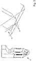
Figure 3 shows a detail view of a portion ofFigure 1 . A scaled-down version ofFigure 1 indicates the location of the portion ofFigure 3 . -
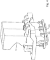
Figure 4 shows a perspective view of a twin chambered combustion system, based on the combustion system ofFigure 1 and showing external ducts. -
Figure 5 shows another perspective view of the twin chambered combustion system ofFigure 4 . -
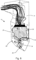
Figure 6 shows a schematic perspective view of the combustion system ofFigure 1 , when in use. -
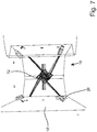
Figure 7 shows a plan view of the combustion system ofFigure 1 , showing air flow from Rotational Under-Fire Air inlets. -
Figure 8 shows a schematic perspective view of a portion of a combustion system according to a second embodiment of the first aspect of the invention, wherein the front face of the combustion system is not shown. -
Figure 9 shows a detail view of a portion ofFigure 8 . - Referring to
Figure 1 , acombustion system 10 has acombustion chamber 12 and aflue gas duct 14. In use, the flue gas duct is above the combustion chamber. - The combustion chamber has a base 16 having two
sides 16a,b that tend towards each other in a direction away from theflue gas duct 14. Thus, effectively, the base is shaped as a hopper having two sides that are aligned and two sides that are oriented towards each other. In this embodiment, the twosides 16a,b of the base 16 are oriented at 52° to each other. - The combustion chamber further has an enclosing
wall 18 connecting the base 16 to theflue gas duct 14. The wall comprises four panels that are arranged to provide a rectangular cross-section. -
Combustion devices 20 are arranged at the four corners of the enclosingwall 18. The devices include burner nozzles that are arranged to supply fuel to the combustion chamber and associated air nozzles that are arranged to supply an airstream to the combustion chamber. - The burner nozzles further include ignition means for igniting the fuel. The burner nozzles and associated air nozzles are oriented so that the fuel / air injected into the combustion chamber follows a rotational path around the longitudinal axis of the combustion chamber. The
combustion devices 20 between them define a combustion zone or burner belt 22 within the combustion chamber. -
Over-fire air nozzles 24 are provided between the combustion zone 22 and theflue gas duct 14, as is known in the art. - Referring to
Figure 2 , Rotational Under-Fire Air nozzles are provided on the enclosingwall 18, between the base 16 and thecombustion devices 20. The Rotational Under-Fire Air nozzles are closer to the base 16 than to thecombustion devices 20, and are typically 1-2m below the combustion devices. - Four Rotational Under-Fire Air nozzles are provided in this embodiment, each nozzle being adjacent to a respective corner of the enclosing wall. The Rotational Under-Fire Air nozzles 26 are arranged to supply a secondary airstream into the combustion chamber along a path that is tangential to an imaginary circle centred on the longitudinal axis of the combustion chamber. The direction of flow around the imaginary circle is the same as for the air and fuel supplied by the
combustion devices 20. The imaginary circle, in this embodiment, has a diameter of about 1.2m. - Referring to
Figure 3 , Separated Under-Fire Air nozzles 28 are provided on theinclined sides 16a,b of thebase 16. The nozzles are arranged to supply a further secondary airstream into the combustion chamber along the axial direction of the chamber. - The Separated Under-Fire Air nozzles are positioned, in this embodiment, at 0.5-2m from the lowest part of the
base 16. The distance between the Secondary Under-Fire Air nozzles in this embodiment and thecombustion devices 20 is about 10m. - Referring to
Figures 4 and5 ,external ducts combustion devices 20, the Rotational Under-Fire Air nozzles 26 and the Separated Under-Fire Air nozzles 28 respectively.External ducts - Referring to
Figure 6 , when the combustion system is in use, air and fuel are injected into the combustion zone bycombustion devices 20, to create afireball 30 that spins around the longitudinal axis of the combustion chamber. The stoichiometric ratio within the fireball is typically 0.65 (excluding under-fire or over-fire air and external leakage into the combustion chamber). - Further air is injected into the combustion chamber underneath the
fireball 30 by the Rotational Under-Fire Air nozzles 26, to create asecondary airstream 32. This airstream also swirls around the longitudinal axis of the combustion chamber, in the same rotational direction as thefireball 30. Thus, the air supplied by the Rotational Under-Fire Air nozzles helps to maintain and support the rotation of thefireball 30, even when low levels of air are provided directly to the fireball by the air nozzles of thecombustion devices 20. Air supplied by the Rotational Under-Fire Air nozzles also helps to oxidise incompletely combusted fuel lying outside thefireball 30. - The flow path of air injected by the Rotational Under-Fire Air nozzles is also shown in
Figure 7 . - A further secondary airstream is injected along the axial direction of the combustion chamber by Separated Under-Fire Air nozzles 28. This airstream helps to oxidise the products of incomplete combustion which gather at the centre of the
fireball 30. - The air supplied to the air nozzles of the
combustion devices 20, the Rotational Under-Fire Air nozzles 26 and the Separated Under-Fire Air nozzles 28 originates from the same duct system and is pressurised by the same fan to a pressure of about 9mbar. It enters the combustion chamber at a velocity of 56 m/s. - The air supplied into the combustion chamber may include chemical agents for the reduction of e.g. SOx and/or NOx, as is known in the art.
- Combustion products leave the combustion chamber along
flue gas duct 14, and may subsequently pass through heat exchangers (not shown), as is known in the art. - The burner belt of the combustion chamber is provided with combustion devices that are known in the art. In the embodiments described above some of the air which is conventionally delivered to these nozzles is removed which reduces NOx production. The air which was removed is redirected with more air to the Separated Under-Fire Air nozzles, Rotational Under-Fire Air nozzles and also to the Over-Fire Air system. Because air has been removed from the combustion devices in the main burner belt then the momentum of that air is not there is help the fireball rotate. Advantageously the redirected Rotational Under-Fire Air adds that momentum back so as to help keep the fireball circulating and to help centralise it in the middle of the furnace. The redirected Separated Under-Fire Air then attacks the unburnt fuel which accumulates in the centre of the fireball and the Over-Fire Air either existing or added or modified by the present invention will help complete combustion of the fuel at the top of the furnace.
- Referring to
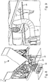
Figures 8 and 9 , a combustion chamber 14' has a base 16' that is shaped as a hopper having two sides that are aligned (not shown) and two angled sides that are oriented towards each other. The two angled sides do not meet, but at their closest point define an aperture therebetween. The two angled sides further extend outwardly from the combustion chamber, such that they extend away from each other in a direction away from the combustion chamber. - Two under-fire air nozzles 28' are provided outside the combustion chamber 14' and arranged to direct gas into the combustion chamber 14' through the aperture provided between the angled sides of the base 16'. The two under-fire air nozzles are connected by a
support brace 92. The two under-fire air nozzles are each mounted in a respective wall of anash hopper 94 that is provided below the combustion chamber. Cross members 98,100 extend between the walls of theash hopper 94 to support thesupport brace 92. In certain embodiments, the cross members 98,100 are omitted.
Claims (6)
- A combustion system (10) comprising a combustion chamber (12) and a flue gas duct (14) located downstream of the combustion chamber to receive combustion products from the combustion chamber,
the combustion chamber having a base (16) and an enclosing wall (18) connecting the base to the flue gas duct,
the combustion chamber being provided with a plurality of combustion devices (20), the combustion devices being configured to deliver fuel and gas into the combustion chamber so as to generate a fireball within a combustion zone (22) in the combustion chamber, the combustion devices further being configured such that the generated fireball rotates about an axis extending between the base and the flue duct,
wherein the system comprises a secondary gas and/or air nozzle (28) at a location upstream of the combustion zone, the nozzle being for delivering gas and/or air into the combustion zone in a direction towards the flue duct, through the centre of the fireball and along its axis of rotation,
and characterized in that a plurality of further secondary gas nozzles (26) is provided at a location upstream of the combustion zone, said plurality of secondary gas nozzles being configured to deliver gas into the combustion chamber so as to create a gas stream that rotates about the axis extending between the base and the duct. - A combustion system according to claim 1, wherein the plurality of secondary gas nozzles are located 0.5-3 metres away from the combustion devices, measured along the axis extending between the base and the flue duct.
- A combustion system according to claim 1 or claim 2, the system being arranged to supply gas to the combustion devices and the plurality of secondary gas nozzles from the
- A combustion system according to claim 3, wherein the gas supplied to the combustion devices and the plurality of secondary gas nozzles is pressurised by the same fan.
- A method of operating a combustion system according to any one of claims 1-4, comprising the step of delivering fuel and gas into the combustion chamber by means of the combustion devices to generate a fireball having a stoichiometry less than 0.9.
- A method of operating a combustion system according to any one of claims 1-4, comprising the step of delivering gas into the combustion chamber via the plurality of secondary gas nozzles at a velocity of 40-70 m/s.
Priority Applications (2)
| Application Number | Priority Date | Filing Date | Title |
|---|---|---|---|
| RS20181497A RS58041B1 (en) | 2013-10-08 | 2014-10-08 | Combustion chamber with air injection systems |
| PL14188201T PL2860447T3 (en) | 2013-10-08 | 2014-10-08 | Combustion chamber with air injection systems |
Applications Claiming Priority (1)
| Application Number | Priority Date | Filing Date | Title |
|---|---|---|---|
| GBGB1317795.1A GB201317795D0 (en) | 2013-10-08 | 2013-10-08 | Air injection systems for combustion chambers |
Publications (3)
| Publication Number | Publication Date |
|---|---|
| EP2860447A2 EP2860447A2 (en) | 2015-04-15 |
| EP2860447A3 EP2860447A3 (en) | 2015-07-08 |
| EP2860447B1 true EP2860447B1 (en) | 2018-09-12 |
Family
ID=49630374
Family Applications (1)
| Application Number | Title | Priority Date | Filing Date |
|---|---|---|---|
| EP14188201.9A Not-in-force EP2860447B1 (en) | 2013-10-08 | 2014-10-08 | Combustion chamber with air injection systems |
Country Status (5)
| Country | Link |
|---|---|
| US (1) | US20150099233A1 (en) |
| EP (1) | EP2860447B1 (en) |
| GB (1) | GB201317795D0 (en) |
| PL (1) | PL2860447T3 (en) |
| RS (1) | RS58041B1 (en) |
Families Citing this family (1)
| Publication number | Priority date | Publication date | Assignee | Title |
|---|---|---|---|---|
| GB2513389A (en) | 2013-04-25 | 2014-10-29 | Rjm Corp Ec Ltd | Nozzle for power station burner and method for the use thereof |
Citations (1)
| Publication number | Priority date | Publication date | Assignee | Title |
|---|---|---|---|---|
| US20060283355A1 (en) * | 2005-06-17 | 2006-12-21 | Knowles Jimmy C | Method and apparatus for turbulent combustion of fly ash |
Family Cites Families (11)
| Publication number | Priority date | Publication date | Assignee | Title |
|---|---|---|---|---|
| US2483728A (en) * | 1945-09-18 | 1949-10-04 | Hercules Powder Co Ltd | Method and apparatus for burning high moisture content fuel |
| US3387574A (en) * | 1966-11-14 | 1968-06-11 | Combustion Eng | System for pneumatically transporting high-moisture fuels such as bagasse and bark and an included furnace for drying and burning those fuels in suspension under high turbulence |
| SU606035A1 (en) * | 1976-04-21 | 1978-05-05 | Предприятие П/Я А-3513 | Combustion chamber |
| SU861845A1 (en) * | 1979-10-04 | 1981-09-07 | Дальневосточный Ордена Трудового Красного Знамени Политехнический Институт Им.В.В.Куйбышева | Fire box |
| JPS5833019A (en) * | 1981-08-21 | 1983-02-26 | Mitsubishi Heavy Ind Ltd | Method of reducing nitrogen oxides in combustion exhaust gas |
| DE3403981A1 (en) * | 1984-02-04 | 1985-08-14 | Deutsche Babcock Werke AG, 4200 Oberhausen | Process and apparatus for the operation of a furnace with a reduced formation of nitrogen oxides |
| JPS6176815A (en) * | 1985-09-13 | 1986-04-19 | Babcock Hitachi Kk | Combustion reducing nitrogen oxide |
| JP2540636B2 (en) * | 1989-11-20 | 1996-10-09 | 三菱重工業株式会社 | boiler |
| JP2004205161A (en) * | 2002-12-26 | 2004-07-22 | Hitachi Ltd | Solid fuel boiler and boiler combustion method |
| JP2011127836A (en) * | 2009-12-17 | 2011-06-30 | Mitsubishi Heavy Ind Ltd | Solid fuel burning burner and solid fuel burning boiler |
| KR20130103774A (en) * | 2010-11-16 | 2013-09-24 | 알스톰 테크놀러지 리미티드 | Apparatus and method of controlling the thermal performance of an oxygen-fired boiler |
-
2013
- 2013-10-08 GB GBGB1317795.1A patent/GB201317795D0/en not_active Ceased
-
2014
- 2014-10-08 RS RS20181497A patent/RS58041B1/en unknown
- 2014-10-08 EP EP14188201.9A patent/EP2860447B1/en not_active Not-in-force
- 2014-10-08 US US14/509,518 patent/US20150099233A1/en not_active Abandoned
- 2014-10-08 PL PL14188201T patent/PL2860447T3/en unknown
Patent Citations (1)
| Publication number | Priority date | Publication date | Assignee | Title |
|---|---|---|---|---|
| US20060283355A1 (en) * | 2005-06-17 | 2006-12-21 | Knowles Jimmy C | Method and apparatus for turbulent combustion of fly ash |
Also Published As
| Publication number | Publication date |
|---|---|
| EP2860447A3 (en) | 2015-07-08 |
| RS58041B1 (en) | 2019-02-28 |
| GB201317795D0 (en) | 2013-11-20 |
| EP2860447A2 (en) | 2015-04-15 |
| PL2860447T3 (en) | 2019-03-29 |
| US20150099233A1 (en) | 2015-04-09 |
Similar Documents
| Publication | Publication Date | Title |
|---|---|---|
| US5839283A (en) | Mixing ducts for a gas-turbine annular combustion chamber | |
| JPH01305206A (en) | Burner | |
| BG64878B1 (en) | Solid fuel burner and method for the adjustment of burning effected by the solid fuel burner | |
| US20130255551A1 (en) | Biomass Combustion | |
| CN103791494A (en) | Air-cooled pulverized coal low-nitrogen combustor and application method thereof | |
| CN102333991A (en) | Solid fuel incineration burners and solid fuel incineration boilers | |
| ITTO940510A1 (en) | LIQUID OR GASEOUS FUEL BURNER WITH VERY REDUCED EMISSION OF NITROGEN OXIDES. | |
| US9696030B2 (en) | Oxy-combustion coupled firing and recirculation system | |
| KR101565691B1 (en) | Solid fuel burner | |
| JP5901737B2 (en) | Burning burner | |
| JP2010270993A (en) | Fuel burner and turning combustion boiler | |
| RU2343356C1 (en) | Annular combustion chamber of gas-turbine engine and method of its operation | |
| MX2014005775A (en) | Oil-fired burner, solid fuel-fired burner unit and solid fuel-fired boiler. | |
| US20040185401A1 (en) | Mixing process for combustion furnaces | |
| CN109690189A (en) | The method and boiler of burning fuel | |
| EP2860447A2 (en) | Air injection systems for combustion chambers | |
| US5899172A (en) | Separated overfire air injection for dual-chambered furnaces | |
| CN105650623A (en) | A combustion system for a boiler | |
| US9599334B2 (en) | Nozzle for power station burner and method for the use thereof | |
| CN201688400U (en) | Powdered coal burner and powdered coal boiler comprising the same | |
| US11988378B2 (en) | Burner and assembly of compact burners | |
| CN104302976B (en) | System And Method For Small-Scale Combustion Of Pulverized Solid Fuels | |
| US20180073728A1 (en) | Downshot burner | |
| RU139936U1 (en) | MALOTOXIC VORTEX DUST-BURNER BURNER WITH MODIFIED AEROSMIX FLOW DISCUPLERS | |
| JP5271680B2 (en) | Swirl combustion boiler |
Legal Events
| Date | Code | Title | Description |
|---|---|---|---|
| PUAI | Public reference made under article 153(3) epc to a published international application that has entered the european phase |
Free format text: ORIGINAL CODE: 0009012 |
|
| 17P | Request for examination filed |
Effective date: 20141008 |
|
| AK | Designated contracting states |
Kind code of ref document: A2 Designated state(s): AL AT BE BG CH CY CZ DE DK EE ES FI FR GB GR HR HU IE IS IT LI LT LU LV MC MK MT NL NO PL PT RO RS SE SI SK SM TR |
|
| AX | Request for extension of the european patent |
Extension state: BA ME |
|
| PUAL | Search report despatched |
Free format text: ORIGINAL CODE: 0009013 |
|
| AK | Designated contracting states |
Kind code of ref document: A3 Designated state(s): AL AT BE BG CH CY CZ DE DK EE ES FI FR GB GR HR HU IE IS IT LI LT LU LV MC MK MT NL NO PL PT RO RS SE SI SK SM TR |
|
| AX | Request for extension of the european patent |
Extension state: BA ME |
|
| RIC1 | Information provided on ipc code assigned before grant |
Ipc: F23C 5/32 20060101ALI20150529BHEP Ipc: F23C 7/02 20060101ALI20150529BHEP Ipc: F23C 6/04 20060101AFI20150529BHEP Ipc: F23L 9/00 20060101ALI20150529BHEP |
|
| R17P | Request for examination filed (corrected) |
Effective date: 20160108 |
|
| RBV | Designated contracting states (corrected) |
Designated state(s): AL AT BE BG CH CY CZ DE DK EE ES FI FR GB GR HR HU IE IS IT LI LT LU LV MC MK MT NL NO PL PT RO RS SE SI SK SM TR |
|
| STAA | Information on the status of an ep patent application or granted ep patent |
Free format text: STATUS: EXAMINATION IS IN PROGRESS |
|
| 17Q | First examination report despatched |
Effective date: 20170822 |
|
| GRAP | Despatch of communication of intention to grant a patent |
Free format text: ORIGINAL CODE: EPIDOSNIGR1 |
|
| STAA | Information on the status of an ep patent application or granted ep patent |
Free format text: STATUS: GRANT OF PATENT IS INTENDED |
|
| INTG | Intention to grant announced |
Effective date: 20180327 |
|
| GRAS | Grant fee paid |
Free format text: ORIGINAL CODE: EPIDOSNIGR3 |
|
| GRAA | (expected) grant |
Free format text: ORIGINAL CODE: 0009210 |
|
| STAA | Information on the status of an ep patent application or granted ep patent |
Free format text: STATUS: THE PATENT HAS BEEN GRANTED |
|
| AK | Designated contracting states |
Kind code of ref document: B1 Designated state(s): AL AT BE BG CH CY CZ DE DK EE ES FI FR GB GR HR HU IE IS IT LI LT LU LV MC MK MT NL NO PL PT RO RS SE SI SK SM TR |
|
| REG | Reference to a national code |
Ref country code: GB Ref legal event code: FG4D |
|
| REG | Reference to a national code |
Ref country code: CH Ref legal event code: EP |
|
| REG | Reference to a national code |
Ref country code: IE Ref legal event code: FG4D |
|
| REG | Reference to a national code |
Ref country code: DE Ref legal event code: R096 Ref document number: 602014032163 Country of ref document: DE |
|
| REG | Reference to a national code |
Ref country code: AT Ref legal event code: REF Ref document number: 1041027 Country of ref document: AT Kind code of ref document: T Effective date: 20181015 |
|
| REG | Reference to a national code |
Ref country code: FR Ref legal event code: PLFP Year of fee payment: 5 |
|
| REG | Reference to a national code |
Ref country code: NL Ref legal event code: MP Effective date: 20180912 |
|
| REG | Reference to a national code |
Ref country code: LT Ref legal event code: MG4D |
|
| PG25 | Lapsed in a contracting state [announced via postgrant information from national office to epo] |
Ref country code: FI Free format text: LAPSE BECAUSE OF FAILURE TO SUBMIT A TRANSLATION OF THE DESCRIPTION OR TO PAY THE FEE WITHIN THE PRESCRIBED TIME-LIMIT Effective date: 20180912 Ref country code: SE Free format text: LAPSE BECAUSE OF FAILURE TO SUBMIT A TRANSLATION OF THE DESCRIPTION OR TO PAY THE FEE WITHIN THE PRESCRIBED TIME-LIMIT Effective date: 20180912 Ref country code: LT Free format text: LAPSE BECAUSE OF FAILURE TO SUBMIT A TRANSLATION OF THE DESCRIPTION OR TO PAY THE FEE WITHIN THE PRESCRIBED TIME-LIMIT Effective date: 20180912 Ref country code: BG Free format text: LAPSE BECAUSE OF FAILURE TO SUBMIT A TRANSLATION OF THE DESCRIPTION OR TO PAY THE FEE WITHIN THE PRESCRIBED TIME-LIMIT Effective date: 20181212 Ref country code: GR Free format text: LAPSE BECAUSE OF FAILURE TO SUBMIT A TRANSLATION OF THE DESCRIPTION OR TO PAY THE FEE WITHIN THE PRESCRIBED TIME-LIMIT Effective date: 20181213 Ref country code: NO Free format text: LAPSE BECAUSE OF FAILURE TO SUBMIT A TRANSLATION OF THE DESCRIPTION OR TO PAY THE FEE WITHIN THE PRESCRIBED TIME-LIMIT Effective date: 20181212 |
|
| PG25 | Lapsed in a contracting state [announced via postgrant information from national office to epo] |
Ref country code: LV Free format text: LAPSE BECAUSE OF FAILURE TO SUBMIT A TRANSLATION OF THE DESCRIPTION OR TO PAY THE FEE WITHIN THE PRESCRIBED TIME-LIMIT Effective date: 20180912 Ref country code: HR Free format text: LAPSE BECAUSE OF FAILURE TO SUBMIT A TRANSLATION OF THE DESCRIPTION OR TO PAY THE FEE WITHIN THE PRESCRIBED TIME-LIMIT Effective date: 20180912 Ref country code: AL Free format text: LAPSE BECAUSE OF FAILURE TO SUBMIT A TRANSLATION OF THE DESCRIPTION OR TO PAY THE FEE WITHIN THE PRESCRIBED TIME-LIMIT Effective date: 20180912 |
|
| REG | Reference to a national code |
Ref country code: AT Ref legal event code: MK05 Ref document number: 1041027 Country of ref document: AT Kind code of ref document: T Effective date: 20180912 |
|
| PG25 | Lapsed in a contracting state [announced via postgrant information from national office to epo] |
Ref country code: NL Free format text: LAPSE BECAUSE OF FAILURE TO SUBMIT A TRANSLATION OF THE DESCRIPTION OR TO PAY THE FEE WITHIN THE PRESCRIBED TIME-LIMIT Effective date: 20180912 Ref country code: ES Free format text: LAPSE BECAUSE OF FAILURE TO SUBMIT A TRANSLATION OF THE DESCRIPTION OR TO PAY THE FEE WITHIN THE PRESCRIBED TIME-LIMIT Effective date: 20180912 Ref country code: EE Free format text: LAPSE BECAUSE OF FAILURE TO SUBMIT A TRANSLATION OF THE DESCRIPTION OR TO PAY THE FEE WITHIN THE PRESCRIBED TIME-LIMIT Effective date: 20180912 Ref country code: AT Free format text: LAPSE BECAUSE OF FAILURE TO SUBMIT A TRANSLATION OF THE DESCRIPTION OR TO PAY THE FEE WITHIN THE PRESCRIBED TIME-LIMIT Effective date: 20180912 Ref country code: IT Free format text: LAPSE BECAUSE OF FAILURE TO SUBMIT A TRANSLATION OF THE DESCRIPTION OR TO PAY THE FEE WITHIN THE PRESCRIBED TIME-LIMIT Effective date: 20180912 Ref country code: RO Free format text: LAPSE BECAUSE OF FAILURE TO SUBMIT A TRANSLATION OF THE DESCRIPTION OR TO PAY THE FEE WITHIN THE PRESCRIBED TIME-LIMIT Effective date: 20180912 Ref country code: IS Free format text: LAPSE BECAUSE OF FAILURE TO SUBMIT A TRANSLATION OF THE DESCRIPTION OR TO PAY THE FEE WITHIN THE PRESCRIBED TIME-LIMIT Effective date: 20190112 |
|
| PG25 | Lapsed in a contracting state [announced via postgrant information from national office to epo] |
Ref country code: SK Free format text: LAPSE BECAUSE OF FAILURE TO SUBMIT A TRANSLATION OF THE DESCRIPTION OR TO PAY THE FEE WITHIN THE PRESCRIBED TIME-LIMIT Effective date: 20180912 Ref country code: PT Free format text: LAPSE BECAUSE OF FAILURE TO SUBMIT A TRANSLATION OF THE DESCRIPTION OR TO PAY THE FEE WITHIN THE PRESCRIBED TIME-LIMIT Effective date: 20190112 Ref country code: SM Free format text: LAPSE BECAUSE OF FAILURE TO SUBMIT A TRANSLATION OF THE DESCRIPTION OR TO PAY THE FEE WITHIN THE PRESCRIBED TIME-LIMIT Effective date: 20180912 |
|
| REG | Reference to a national code |
Ref country code: CH Ref legal event code: PL |
|
| REG | Reference to a national code |
Ref country code: DE Ref legal event code: R097 Ref document number: 602014032163 Country of ref document: DE |
|
| REG | Reference to a national code |
Ref country code: BE Ref legal event code: MM Effective date: 20181031 |
|
| PG25 | Lapsed in a contracting state [announced via postgrant information from national office to epo] |
Ref country code: LU Free format text: LAPSE BECAUSE OF NON-PAYMENT OF DUE FEES Effective date: 20181008 |
|
| PLBE | No opposition filed within time limit |
Free format text: ORIGINAL CODE: 0009261 |
|
| STAA | Information on the status of an ep patent application or granted ep patent |
Free format text: STATUS: NO OPPOSITION FILED WITHIN TIME LIMIT |
|
| REG | Reference to a national code |
Ref country code: IE Ref legal event code: MM4A |
|
| PG25 | Lapsed in a contracting state [announced via postgrant information from national office to epo] |
Ref country code: DK Free format text: LAPSE BECAUSE OF FAILURE TO SUBMIT A TRANSLATION OF THE DESCRIPTION OR TO PAY THE FEE WITHIN THE PRESCRIBED TIME-LIMIT Effective date: 20180912 Ref country code: MC Free format text: LAPSE BECAUSE OF FAILURE TO SUBMIT A TRANSLATION OF THE DESCRIPTION OR TO PAY THE FEE WITHIN THE PRESCRIBED TIME-LIMIT Effective date: 20180912 |
|
| 26N | No opposition filed |
Effective date: 20190613 |
|
| PG25 | Lapsed in a contracting state [announced via postgrant information from national office to epo] |
Ref country code: LI Free format text: LAPSE BECAUSE OF NON-PAYMENT OF DUE FEES Effective date: 20181031 Ref country code: SI Free format text: LAPSE BECAUSE OF FAILURE TO SUBMIT A TRANSLATION OF THE DESCRIPTION OR TO PAY THE FEE WITHIN THE PRESCRIBED TIME-LIMIT Effective date: 20180912 Ref country code: BE Free format text: LAPSE BECAUSE OF NON-PAYMENT OF DUE FEES Effective date: 20181031 Ref country code: CH Free format text: LAPSE BECAUSE OF NON-PAYMENT OF DUE FEES Effective date: 20181031 |
|
| PG25 | Lapsed in a contracting state [announced via postgrant information from national office to epo] |
Ref country code: IE Free format text: LAPSE BECAUSE OF NON-PAYMENT OF DUE FEES Effective date: 20181008 |
|
| PG25 | Lapsed in a contracting state [announced via postgrant information from national office to epo] |
Ref country code: MT Free format text: LAPSE BECAUSE OF NON-PAYMENT OF DUE FEES Effective date: 20181008 |
|
| PG25 | Lapsed in a contracting state [announced via postgrant information from national office to epo] |
Ref country code: TR Free format text: LAPSE BECAUSE OF FAILURE TO SUBMIT A TRANSLATION OF THE DESCRIPTION OR TO PAY THE FEE WITHIN THE PRESCRIBED TIME-LIMIT Effective date: 20180912 |
|
| PG25 | Lapsed in a contracting state [announced via postgrant information from national office to epo] |
Ref country code: HU Free format text: LAPSE BECAUSE OF FAILURE TO SUBMIT A TRANSLATION OF THE DESCRIPTION OR TO PAY THE FEE WITHIN THE PRESCRIBED TIME-LIMIT; INVALID AB INITIO Effective date: 20141008 Ref country code: MK Free format text: LAPSE BECAUSE OF NON-PAYMENT OF DUE FEES Effective date: 20180912 Ref country code: CY Free format text: LAPSE BECAUSE OF FAILURE TO SUBMIT A TRANSLATION OF THE DESCRIPTION OR TO PAY THE FEE WITHIN THE PRESCRIBED TIME-LIMIT Effective date: 20180912 |
|
| PGFP | Annual fee paid to national office [announced via postgrant information from national office to epo] |
Ref country code: CZ Payment date: 20211008 Year of fee payment: 8 Ref country code: DE Payment date: 20211028 Year of fee payment: 8 |
|
| PGFP | Annual fee paid to national office [announced via postgrant information from national office to epo] |
Ref country code: FR Payment date: 20211027 Year of fee payment: 8 |
|
| PG25 | Lapsed in a contracting state [announced via postgrant information from national office to epo] |
Ref country code: CZ Free format text: LAPSE BECAUSE OF NON-PAYMENT OF DUE FEES Effective date: 20221008 |
|
| REG | Reference to a national code |
Ref country code: DE Ref legal event code: R119 Ref document number: 602014032163 Country of ref document: DE |
|
| PG25 | Lapsed in a contracting state [announced via postgrant information from national office to epo] |
Ref country code: FR Free format text: LAPSE BECAUSE OF NON-PAYMENT OF DUE FEES Effective date: 20221031 Ref country code: DE Free format text: LAPSE BECAUSE OF NON-PAYMENT OF DUE FEES Effective date: 20230503 |
|
| PGFP | Annual fee paid to national office [announced via postgrant information from national office to epo] |
Ref country code: PL Payment date: 20230927 Year of fee payment: 10 |
|
| PGFP | Annual fee paid to national office [announced via postgrant information from national office to epo] |
Ref country code: GB Payment date: 20231024 Year of fee payment: 10 |
|
| PGFP | Annual fee paid to national office [announced via postgrant information from national office to epo] |
Ref country code: RS Payment date: 20231005 Year of fee payment: 10 |
|
| PG25 | Lapsed in a contracting state [announced via postgrant information from national office to epo] |
Ref country code: RS Free format text: LAPSE BECAUSE OF NON-PAYMENT OF DUE FEES Effective date: 20241008 |
|
| GBPC | Gb: european patent ceased through non-payment of renewal fee |
Effective date: 20241008 |
|
| PG25 | Lapsed in a contracting state [announced via postgrant information from national office to epo] |
Ref country code: GB Free format text: LAPSE BECAUSE OF NON-PAYMENT OF DUE FEES Effective date: 20241008 |
|
| PG25 | Lapsed in a contracting state [announced via postgrant information from national office to epo] |
Ref country code: PL Free format text: LAPSE BECAUSE OF NON-PAYMENT OF DUE FEES Effective date: 20241008 |