EP2860400A2 - Hydraulically actuated diaphragm pumps - Google Patents
Hydraulically actuated diaphragm pumps Download PDFInfo
- Publication number
- EP2860400A2 EP2860400A2 EP14183377.2A EP14183377A EP2860400A2 EP 2860400 A2 EP2860400 A2 EP 2860400A2 EP 14183377 A EP14183377 A EP 14183377A EP 2860400 A2 EP2860400 A2 EP 2860400A2
- Authority
- EP
- European Patent Office
- Prior art keywords
- piston
- motor
- pump
- hydraulic fluid
- chamber
- Prior art date
- Legal status (The legal status is an assumption and is not a legal conclusion. Google has not performed a legal analysis and makes no representation as to the accuracy of the status listed.)
- Withdrawn
Links
- 239000012530 fluid Substances 0.000 claims abstract description 105
- 238000005086 pumping Methods 0.000 claims abstract description 25
- 230000008602 contraction Effects 0.000 claims abstract description 5
- 230000007246 mechanism Effects 0.000 claims description 16
- 238000000034 method Methods 0.000 claims description 12
- 238000001514 detection method Methods 0.000 claims description 8
- 230000003213 activating effect Effects 0.000 claims description 2
- 238000004891 communication Methods 0.000 description 7
- 230000008901 benefit Effects 0.000 description 3
- 230000007423 decrease Effects 0.000 description 3
- 238000000926 separation method Methods 0.000 description 2
- 230000005355 Hall effect Effects 0.000 description 1
- 238000012986 modification Methods 0.000 description 1
- 230000004048 modification Effects 0.000 description 1
Images
Classifications
-
- F—MECHANICAL ENGINEERING; LIGHTING; HEATING; WEAPONS; BLASTING
- F04—POSITIVE - DISPLACEMENT MACHINES FOR LIQUIDS; PUMPS FOR LIQUIDS OR ELASTIC FLUIDS
- F04B—POSITIVE-DISPLACEMENT MACHINES FOR LIQUIDS; PUMPS
- F04B9/00—Piston machines or pumps characterised by the driving or driven means to or from their working members
- F04B9/02—Piston machines or pumps characterised by the driving or driven means to or from their working members the means being mechanical
- F04B9/04—Piston machines or pumps characterised by the driving or driven means to or from their working members the means being mechanical the means being cams, eccentrics or pin-and-slot mechanisms
- F04B9/045—Piston machines or pumps characterised by the driving or driven means to or from their working members the means being mechanical the means being cams, eccentrics or pin-and-slot mechanisms the means being eccentrics
-
- F—MECHANICAL ENGINEERING; LIGHTING; HEATING; WEAPONS; BLASTING
- F04—POSITIVE - DISPLACEMENT MACHINES FOR LIQUIDS; PUMPS FOR LIQUIDS OR ELASTIC FLUIDS
- F04B—POSITIVE-DISPLACEMENT MACHINES FOR LIQUIDS; PUMPS
- F04B43/00—Machines, pumps, or pumping installations having flexible working members
- F04B43/02—Machines, pumps, or pumping installations having flexible working members having plate-like flexible members, e.g. diaphragms
- F04B43/025—Machines, pumps, or pumping installations having flexible working members having plate-like flexible members, e.g. diaphragms two or more plate-like pumping members in parallel
- F04B43/026—Machines, pumps, or pumping installations having flexible working members having plate-like flexible members, e.g. diaphragms two or more plate-like pumping members in parallel each plate-like pumping flexible member working in its own pumping chamber
-
- F—MECHANICAL ENGINEERING; LIGHTING; HEATING; WEAPONS; BLASTING
- F04—POSITIVE - DISPLACEMENT MACHINES FOR LIQUIDS; PUMPS FOR LIQUIDS OR ELASTIC FLUIDS
- F04B—POSITIVE-DISPLACEMENT MACHINES FOR LIQUIDS; PUMPS
- F04B43/00—Machines, pumps, or pumping installations having flexible working members
- F04B43/02—Machines, pumps, or pumping installations having flexible working members having plate-like flexible members, e.g. diaphragms
- F04B43/06—Pumps having fluid drive
- F04B43/067—Pumps having fluid drive the fluid being actuated directly by a piston
-
- F—MECHANICAL ENGINEERING; LIGHTING; HEATING; WEAPONS; BLASTING
- F04—POSITIVE - DISPLACEMENT MACHINES FOR LIQUIDS; PUMPS FOR LIQUIDS OR ELASTIC FLUIDS
- F04B—POSITIVE-DISPLACEMENT MACHINES FOR LIQUIDS; PUMPS
- F04B49/00—Control, e.g. of pump delivery, or pump pressure of, or safety measures for, machines, pumps, or pumping installations, not otherwise provided for, or of interest apart from, groups F04B1/00 - F04B47/00
- F04B49/06—Control using electricity
- F04B49/065—Control using electricity and making use of computers
-
- F—MECHANICAL ENGINEERING; LIGHTING; HEATING; WEAPONS; BLASTING
- F04—POSITIVE - DISPLACEMENT MACHINES FOR LIQUIDS; PUMPS FOR LIQUIDS OR ELASTIC FLUIDS
- F04B—POSITIVE-DISPLACEMENT MACHINES FOR LIQUIDS; PUMPS
- F04B2201/00—Pump parameters
- F04B2201/02—Piston parameters
- F04B2201/0206—Length of piston stroke
-
- F—MECHANICAL ENGINEERING; LIGHTING; HEATING; WEAPONS; BLASTING
- F04—POSITIVE - DISPLACEMENT MACHINES FOR LIQUIDS; PUMPS FOR LIQUIDS OR ELASTIC FLUIDS
- F04B—POSITIVE-DISPLACEMENT MACHINES FOR LIQUIDS; PUMPS
- F04B2201/00—Pump parameters
- F04B2201/12—Parameters of driving or driven means
- F04B2201/1202—Torque on the axis
-
- F—MECHANICAL ENGINEERING; LIGHTING; HEATING; WEAPONS; BLASTING
- F04—POSITIVE - DISPLACEMENT MACHINES FOR LIQUIDS; PUMPS FOR LIQUIDS OR ELASTIC FLUIDS
- F04B—POSITIVE-DISPLACEMENT MACHINES FOR LIQUIDS; PUMPS
- F04B2203/00—Motor parameters
- F04B2203/02—Motor parameters of rotating electric motors
- F04B2203/0201—Current
Definitions
- the present disclosure relates, generally, to diaphragm pumps and, more particularly, to hydraulically actuated diaphragm pumps.
- Pneumatic diaphragm pumps have been used for pumping one or more fluids.
- Pneumatic diaphragm pumps generally include at least one pumping chamber having a diaphragm separating a motive fluid chamber for moving a motive fluid and a pump chamber for pumping a working fluid. Compressed air is fed into the motive fluid chamber to expand the diaphragm, which, in turn, causes the working fluid to be pumped through an outlet of the pump chamber. While pneumatic diaphragm pumps utilizing compressed air are effective, they may also be very inefficient and, thus, very costly.
- a diaphragm pump may comprise a housing defining a first pumping chamber, a second pumping chamber, and a hydraulic fluid chamber, a first flexible diaphragm separating the first pumping chamber from the hydraulic fluid chamber, a second flexible diaphragm separating the second pumping chamber from the hydraulic fluid chamber, a rod mechanically linking the first flexible diaphragm and the second flexible diaphragm such that an expansion of one of the first and second flexible diaphragms exerts a contraction force on the other of the first and second flexible diaphragms, and a piston disposed within the hydraulic fluid chamber and configured to reciprocate to cause a hydraulic fluid contained within the hydraulic fluid chamber to alternately exert an expansion force on the first and second flexible diaphragms.
- the diaphragm pump may further comprise a motor operatively connected to the piston to cause reciprocal movement of the piston.
- the motor may comprise a rotatable output shaft, an arm having a first end attached to the output shaft, and a roller bearing attached to a second end of the arm opposite the first end.
- the piston may comprise a cavity receiving the roller bearing, such that rotation of the output shaft causes movement of the roller bearing within the cavity, thereby causing reciprocal movement of the piston.
- the diaphragm pump may further comprise a mechanism configured to deactivate the motor upon detection of a stall in the pump.
- the mechanism may comprise one or more motion sensors configured to sense ends of a stroke of the piston.
- the mechanism may comprise a motor overcurrent detection circuit configured to measure a current drawn by the motor and to deactivate the motor when the current is greater than a pre-determined level.
- the mechanism may comprise a clutch disposed between the output shaft of the motor and the piston, the clutch being configured to disengage when a torque between the output shaft and the piston exceeds a mechanically-set threshold.
- a diaphragm pump may comprise a housing defining a first working chamber and a second working chamber, a first flexible diaphragm separating the first working chamber into a first pump chamber and a first motive fluid chamber, a second flexible diaphragm separating the second working chamber into a second pump chamber and a second motive fluid chamber, a channel in fluid communication with the first and second motive fluid chambers, a rod mechanically linking the first and second flexible diaphragms, a piston disposed within the channel and configured to reciprocate to cause a hydraulic fluid contained within the channel and the first and second motive fluid chambers to alternately exert an expansion force on the first and second flexible diaphragms, a motor operatively connected to the piston and configured to drive reciprocal movement of the piston, and a clutch operatively connected between an output shaft of the motor and the piston, the clutch being configured to deactivate the motor upon detection of an overload condition.
- the rod may be configured to simultaneously contract one of the first and second flexible diaphragms as the other of the first and second flexible diaphragms expands.
- the motor may further comprise an arm having a first end attached to the output shaft and a roller bearing attached to a second end of the arm opposite the first end.
- the piston may comprise a cavity receiving the roller bearing, such that rotation of the output shaft causes movement of the roller bearing within the cavity, thereby causing reciprocal movement of the piston.
- the clutch may be configured to be engaged when a torque between the output shaft and the piston is below a mechanically-set threshold and to be disengaged when the torque between the output shaft and the piston exceeds the mechanically-set threshold.
- a method of operating a diaphragm pump comprising a housing defining first and second pumping chambers and a hydraulic fluid chamber, a first flexible diaphragm separating the first pumping chamber from the hydraulic fluid chamber, a second flexible diaphragm separating the second pumping chamber from the hydraulic fluid chamber, a rod mechanically linking the first and second diaphragms, a piston disposed within the hydraulic fluid chamber, and a motor operatively connected to the piston is disclosed.
- the method may comprise activating the motor to drive reciprocal movement of the piston, the reciprocal movement of the piston causing alternating expansion of the first and second flexible diaphragms, the rod causing alternating contraction of the first and second flexible diaphragms, and deactivating the motor upon detection of a stall condition within the pump.
- deactivating the motor may comprise disengaging a clutch operatively connected between an output shaft of the motor and the piston when a torque between the output shaft and the piston exceeds a mechanically-set threshold.
- Deactivating the motor may comprise measuring a current drawn by the motor and deactivating the motor if the measured current is greater than a pre-determined level.
- Deactivating the motor may comprise sensing motion of the piston near an end of a stroke of the piston and deactivating the motor if motion of the piston has not been detected for a pre-determined period of time.
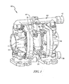
- FIG. 1 a diaphragm pump 10 is shown.
- the pump 10 of FIG. 1 is illustratively embodied in FIG. 2 as a pneumatically actuated double-diaphragm pump. It is contemplated that, in other embodiments, the pump 10 may be embodied as any other type of diaphragm pump.
- the pump 10 has a housing 12 that defines a first working or pumping chamber 14 and a second working or pumping chamber 16.
- the housing 12 is comprised of three sections coupled together by fasteners.
- the first and second working chambers 14, 16 of the pump 10 are each divided by respective first and second flexible diaphragms 18, 20 into respective first and second pump chambers 22, 24 and first and second motive fluid chambers 26, 28.
- the diaphragms 18, 20 are interconnected by a rod or shaft 30, such that when the diaphragm 18 is moved to increase the volume of the associated pump chamber 22, the other diaphragm 20 is simultaneously moved to decrease the volume of the associated pump chamber 24, and vice versa.
- the shaft 30 illustrated in FIG. 2 is a reciprocating diaphragm link rod having a fixed length, such that the position of the shaft 30 in the pump 10 is indicative of the position of the diaphragms 18, 20.
- the shaft 30 and diaphragms 18, 20 move back and forth a fixed distance that defines a stroke.
- the fixed distance is determined by the geometry of the pump 10, the shaft 30, the diaphragms 18, 20, and other components of the pump 10 (e.g., the diaphragm washers).
- a stroke is defined as the travel path of the shaft 30 between first and second end-of-stroke positions. Movement of the shaft 30 from one end-of-stroke position to the other end-of-stroke position and back defines a cycle of operation of the shaft 30 ( i.e., a cycle includes two consecutive strokes).
- the pump 10 includes one or more inlets 32 for the supply of a motive fluid (e.g., compressed air, or another pressurized gas) to the first and second motive fluid chambers 26, 28 to drive reciprocation of the diaphragms 18, 20 and the shaft 30.
- a motive fluid e.g., compressed air, or another pressurized gas
- the pump 10 may be alternately connected to the inlets 32.
- one or more valves 34 may be connected to one or more inlets for alternately supplying the motive fluid to the first and second motive fluid chambers 26, 28.
- the valve 34 supplies motive fluid to the motive fluid chamber 26
- the valve 34 places an exhaust assembly 36 in communication with the other motive fluid chamber 28 to permit motive fluid to be expelled therefrom.
- the valve 34 supplies motive fluid to the motive fluid chamber 28
- the valve 34 places the motive fluid chamber 26 in communication with the exhaust assembly 36.
- valve 34 movement of the valve 34 between these positions is controlled by a solenoid valve.
- the solenoid valve of the pump 10 controls the supply of the motive fluid to the first and second motive fluid chambers 26, 28.
- the first and second pump chambers 22, 24 alternately expand and contract to create respective low and high pressure within the respective first and second pump chambers 22, 24.
- the pump chambers 22, 24 each communicate with an inlet manifold 38, 40 that may be connected to a source of fluid 41, 43, respectively, to be pumped and also each communicate with an outlet manifold, or fluid outlet, 42, 44 that may be connected to a receptacle for the fluid 41, 43 being pumped.
- Check valves 46, 48 ensure that the fluid 41, 43 being pumped moves only from the inlet manifold 38, 40 toward the outlet manifold 42, 44 when an appropriate amount of vacuum pressure is stored within the respective motive fluid chamber 26, 28.
- the check valves 46, 48 are shown in an upper position when fluid 41, 43 within the pump chambers 22, 24 is to be pumped from the respective chamber and in a lower position when fluid 41, 43 within the pump chambers is to remain within the respective chamber.
- the pump chamber 22 expands, the resulting negative pressure draws fluid 41 from the inlet manifold 38 into the pump chamber 22.
- the other pump chamber 24 contracts, which creates positive pressure to force fluid 43 contained therein into the outlet manifold 44.
- the pump chamber 22 will contract and the pump chamber 24 will expand (forcing fluid 41 contained in the pump chamber 22 into the outlet manifold 42 and drawing fluid 43 from the inlet manifold 40 into the pump chamber 24).
- the pump 100 has a housing, for example, similar to the housing 12 seen in FIG. 1 .
- the housing of the pump 100 defines a first working or pumping chamber 114 and a second working or pumping chamber 116.
- the first and second working chambers 114, 116 of the pump 100 are each divided by respective first and second flexible diaphragms 118, 120 into respective first and second pump chambers 122, 124 and first and second motive fluid chambers 126, 128.
- the diaphragms 118, 120 are interconnected by a rod or shaft 130, such that when the diaphragm 118 is moved to increase the volume of the associated pump chamber 122, the other diaphragm 120 is simultaneously moved to decrease the volume of the associated pump chamber 124, and vice versa.
- the shaft 130 illustrated in FIG. 3 is a reciprocating diaphragm link rod having a fixed length, such that the position of the shaft 30 in the pump 10 is indicative of the position of the diaphragms 118, 120.
- the shaft 130 may be attached to the diaphragms 118, 120 by plastic washers or in any other suitable manner.
- the shaft 130 and diaphragms 118, 120 move back and forth a fixed distance that defines a stroke.
- the fixed distance is determined by the geometry of the pump 100, the shaft 130, the diaphragms 118, 120, and other components of the pump 100 (e.g., the diaphragm washers).
- a stroke is defined as the travel path of the shaft 130 between first and second end-of-stroke positions. Movement of the shaft 130 from one end-of-stroke position to the other end-of-stroke position and back defines a cycle of operation of the shaft 130 ( i.e., a cycle includes two consecutive strokes).
- the shaft 130 extends through the first and second motive fluid chambers 126, 128 and through a channel 160, for example a cylindrical channel, extending between and in fluid communication with the motive fluid chambers 126, 128.
- An electric motor 162 for example an alternating current or direct current motor, is operatively connected to the shaft 130 to move the shaft 130 back and forth (i.e., left and right, as seen in FIG. 3 ).
- the electric motor 162 may include a rotor 164 that may be rotated, for example, in a counterclockwise direction.
- An arm 166 extends outwardly from the rotor 164 and includes a roller bearing 168 on an end thereof. The roller bearing 168 is accepted and rides within a cavity 170 of a piston 172, wherein the cavity 170 has a longitudinal extent that may be generally perpendicular to movement of the piston 172.
- an amount of motive fluid F1 in the motive fluid chamber 126 and a portion of the channel 160 in fluid communication with the motive fluid chamber 126 may be generally the same as an amount of motive fluid F2 in the motive fluid chamber 128 and a portion of the channel 160 in fluid communication with the motive fluid chamber 128.
- the arm 166 and the roller bearing 168 rotate with the output shaft 164.
- the roller bearing 168 moves back and forth along the cavity 170 of a piston 172 to accommodate the rotation of the arm 166.
- the piston 172 is moved along the channel 160 toward the chamber 114.
- the piston 172 is moved along the channel 160 toward the chamber 116.
- the piston 172 may be positioned within the channel 160 such that the motive fluids F1, F2 may be prevented from passing the piston 172.
- a seal may be formed around one or more portions of the piston 172 to prevent movement of motive fluid F1, F2 past the piston 172, while still allowing movement of the piston 172.
- the overall space in which the motive fluids F1, F2 are held increases and decreases, thereby causing alternating low and high pressure against the flexible diaphragms 118, 120, which, in turn, causes the flexible diaphragms 118, 120 to contract and expand.
- each of the pump chambers 122, 124 communicates with an inlet manifold 200, 202 that may be connected to a source of fluid 204, 206 to be pumped.
- Each of the pump chambers 122, 124 also communicates with an outlet manifold, or fluid outlet 208, 210.
- Check valves 212, 214 ensure that the fluid 204, 206 being pumped moves only from the inlet manifold 200, 202 toward the outlet manifold 208, 210 when an appropriate amount of vacuum pressure is stored within the respective motive fluid chamber 126, 128.
- the check valves 212, 214 are shown in an upper position when fluid 204, 206 within the pump chambers 122, 124 is to be pumped from the respective chamber and in a lower position when fluid 204, 206 within the pump chambers 122, 124 is to remain within the respective chamber.
- the pump chamber 122 expands, the resulting negative pressure draws fluid 204 from the inlet manifold 200 into the pump chamber 122.
- the other pump chamber 124 contracts, which creates positive pressure to force fluid 206 contained therein into the outlet manifold 210.
- the pump chamber 122 will contract and the pump chamber 124 will expand (forcing fluid 204 contained in the pump chamber 122 into the outlet manifold 208 and drawing fluid 206 from the respective inlet manifold 202 into the pump chamber 124).
- a mechanism for overload or stall protection may be implemented within the pump 100 of FIG. 3 to protect the electric motor 162 from a potentially damaging condition wherein a main hydraulic pump output is blocked or does not permit free operation.
- the motor 162 would generally continue providing rotational energy to the output shaft 164, thereby creating the potential for damage to the motor 162.
- the methods of stall protection disclosed herein may halt operation of the motor 162 in the presence of potentially damaging conditions.
- an overload clutch 220 may be positioned between the output shaft 164 of the electric motor 162 and the piston 172.
- the overload clutch 220 may generally include first and second discs 222, 224 attached to the rotatable output shaft 164 of the motor 162 and a shaft 225 extending between the second disc 224 and the arm 166, respectively.
- First and second clutch gears 226, 228 are attached to the output shaft 164 and the shaft 225, respectively, and are biased into engagement by springs 230, 232 disposed between the clutch gears 226, 228 and the discs 222, 224.
- the output shaft 164 rotates the gears 226, 228, as seen in FIG. 5 , which transfer rotational energy to the shaft 225, the arm 166 and the roller bearing 168, which causes reciprocating movement of the piston 172. If the piston 172 is not moving freely (or other issues are present with the pump 100 and/or piston 172), the second clutch gear 228 remains stationary, as seen in FIG. 6 . When a torque between the output shaft 164 of the motor 162 and the piston 172 is below a mechanically-set threshold of the overload clutch 220, no relative movement between the clutch gears 226, 228 occurs.
- the stall protection may be implanted within circuitry as a motor overcurrent detection circuit that may deactivate the motor 162 when a measured current drawn by the electric motor 162 is greater than a pre-determined safe level.
- a position of the piston 172 may be monitored by motion sensors (e.g., Hall effect sensors) mounted at or near an end of each piston stroke. If no signal is received from a sensor within a particular time interval (e.g., due to a blockage in the system, breakage of the connection between the motor 162 and the piston 172, etc.), the motor 162 may be deactivated.
- motion sensors e.g., Hall effect sensors
- the pump 100 may include one or more mechanisms for compensating for leakage within the pump 100, for example, from the motive fluid chambers 126, 128. At times, motive fluid F1 or F2 may escape from the pump 100, which can create issues with operation of the pump 100. It is therefore desirable to replace lost motive fluid F1, F2.
- a leakage compensation mechanism is depicted as having two ports 300, 302 within an upper wall 304 of the channel 160. Each port 300, 302 may be in fluid communication with a respective motive fluid reservoir 306, 308 containing motive fluid.
- the motive fluid reservoirs 306, 308 may be positioned adjacent the upper wall 304 of the channel 160 and may be of any size and/or shape.
- the piston 172 may alternatingly block and unblock the ports 300, 302. More specifically, as the piston 172 reaches the end of a stroke, for example in its right-most position in which no pressure is exerted on the motive fluid F1, as seen in FIG. 3 , the piston 172 would no longer block the port 300 (and would block the port 302). Similarly, as the piston 172 reaches its left-most position in which no pressure is exerted on the motive fluid F2, the piston 172 would no longer block the port 302 (and would block the port 300). In this manner, the ports 300, 302 would only be unblocked at the end of a stroke.
- the rod 130 may be positioned toward the inlet manifolds 200, 202 or toward the outlet manifolds 208, 210. In alternative embodiments, any other suitable mechanism or method for compensating for leakage may be additionally or alternatively used within the pump 100.
Landscapes
- Engineering & Computer Science (AREA)
- Mechanical Engineering (AREA)
- General Engineering & Computer Science (AREA)
- Computer Hardware Design (AREA)
- Reciprocating Pumps (AREA)
Abstract
Description
- The present disclosure relates, generally, to diaphragm pumps and, more particularly, to hydraulically actuated diaphragm pumps.
- Pneumatic diaphragm pumps have been used for pumping one or more fluids. Pneumatic diaphragm pumps generally include at least one pumping chamber having a diaphragm separating a motive fluid chamber for moving a motive fluid and a pump chamber for pumping a working fluid. Compressed air is fed into the motive fluid chamber to expand the diaphragm, which, in turn, causes the working fluid to be pumped through an outlet of the pump chamber. While pneumatic diaphragm pumps utilizing compressed air are effective, they may also be very inefficient and, thus, very costly.
- According to one aspect, a diaphragm pump may comprise a housing defining a first pumping chamber, a second pumping chamber, and a hydraulic fluid chamber, a first flexible diaphragm separating the first pumping chamber from the hydraulic fluid chamber, a second flexible diaphragm separating the second pumping chamber from the hydraulic fluid chamber, a rod mechanically linking the first flexible diaphragm and the second flexible diaphragm such that an expansion of one of the first and second flexible diaphragms exerts a contraction force on the other of the first and second flexible diaphragms, and a piston disposed within the hydraulic fluid chamber and configured to reciprocate to cause a hydraulic fluid contained within the hydraulic fluid chamber to alternately exert an expansion force on the first and second flexible diaphragms.
- In some embodiments, the diaphragm pump may further comprise a motor operatively connected to the piston to cause reciprocal movement of the piston. The motor may comprise a rotatable output shaft, an arm having a first end attached to the output shaft, and a roller bearing attached to a second end of the arm opposite the first end. The piston may comprise a cavity receiving the roller bearing, such that rotation of the output shaft causes movement of the roller bearing within the cavity, thereby causing reciprocal movement of the piston.
- In some embodiments, the diaphragm pump may further comprise a mechanism configured to deactivate the motor upon detection of a stall in the pump. The mechanism may comprise one or more motion sensors configured to sense ends of a stroke of the piston. The mechanism may comprise a motor overcurrent detection circuit configured to measure a current drawn by the motor and to deactivate the motor when the current is greater than a pre-determined level. The mechanism may comprise a clutch disposed between the output shaft of the motor and the piston, the clutch being configured to disengage when a torque between the output shaft and the piston exceeds a mechanically-set threshold.
- According to another aspect, a diaphragm pump may comprise a housing defining a first working chamber and a second working chamber, a first flexible diaphragm separating the first working chamber into a first pump chamber and a first motive fluid chamber, a second flexible diaphragm separating the second working chamber into a second pump chamber and a second motive fluid chamber, a channel in fluid communication with the first and second motive fluid chambers, a rod mechanically linking the first and second flexible diaphragms, a piston disposed within the channel and configured to reciprocate to cause a hydraulic fluid contained within the channel and the first and second motive fluid chambers to alternately exert an expansion force on the first and second flexible diaphragms, a motor operatively connected to the piston and configured to drive reciprocal movement of the piston, and a clutch operatively connected between an output shaft of the motor and the piston, the clutch being configured to deactivate the motor upon detection of an overload condition.
- In some embodiments, the rod may be configured to simultaneously contract one of the first and second flexible diaphragms as the other of the first and second flexible diaphragms expands. The motor may further comprise an arm having a first end attached to the output shaft and a roller bearing attached to a second end of the arm opposite the first end. The piston may comprise a cavity receiving the roller bearing, such that rotation of the output shaft causes movement of the roller bearing within the cavity, thereby causing reciprocal movement of the piston. The clutch may be configured to be engaged when a torque between the output shaft and the piston is below a mechanically-set threshold and to be disengaged when the torque between the output shaft and the piston exceeds the mechanically-set threshold.
- According to yet another aspect, a method of operating a diaphragm pump comprising a housing defining first and second pumping chambers and a hydraulic fluid chamber, a first flexible diaphragm separating the first pumping chamber from the hydraulic fluid chamber, a second flexible diaphragm separating the second pumping chamber from the hydraulic fluid chamber, a rod mechanically linking the first and second diaphragms, a piston disposed within the hydraulic fluid chamber, and a motor operatively connected to the piston is disclosed. The method may comprise activating the motor to drive reciprocal movement of the piston, the reciprocal movement of the piston causing alternating expansion of the first and second flexible diaphragms, the rod causing alternating contraction of the first and second flexible diaphragms, and deactivating the motor upon detection of a stall condition within the pump.
- In some embodiments, deactivating the motor may comprise disengaging a clutch operatively connected between an output shaft of the motor and the piston when a torque between the output shaft and the piston exceeds a mechanically-set threshold. Deactivating the motor may comprise measuring a current drawn by the motor and deactivating the motor if the measured current is greater than a pre-determined level. Deactivating the motor may comprise sensing motion of the piston near an end of a stroke of the piston and deactivating the motor if motion of the piston has not been detected for a pre-determined period of time.
- The invention will now be further described by way of example with reference to the accompanying drawings, in which:
-
FIG. 1 is a front perspective view of at least one embodiment of a double diaphragm pump; -
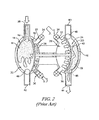
FIG. 2 is a schematic cross-sectional view of a prior art pump that may be embodied within the pump housing ofFIG. 1 ; -
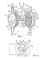
FIG. 3 is a schematic cross-sectional view of an embodiment of a hydraulically actuated pump that may be embodied within the pump housing ofFIG. 1 ; -
FIG. 4 is a schematic view of an exemplary hydraulic drive mechanism in the form of a motor-piston drive mechanism that may be used with the pump ofFIG. 3 ; -
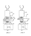
FIG. 5 is an elevational view of an exemplary hydraulic drive mechanism that may be used with the pump ofFIG. 3 , wherein an overload clutch is depicted in an engaged condition; and -
FIG. 6 is an elevational view of the hydraulic drive mechanism ofFIG. 5 with the overload clutch depicted in a disengaged or separated condition. - While the concepts of the present disclosure are susceptible to various modifications and alternative forms, specific exemplary embodiments thereof have been shown by way of example in the drawings and will herein be described in detail. It should be understood, however, that there is no intent to limit the concepts of the present disclosure to the particular forms disclosed.
- Referring now to
FIG. 1 , adiaphragm pump 10 is shown. Thepump 10 ofFIG. 1 is illustratively embodied inFIG. 2 as a pneumatically actuated double-diaphragm pump. It is contemplated that, in other embodiments, thepump 10 may be embodied as any other type of diaphragm pump. In the illustrative embodiment, thepump 10 has ahousing 12 that defines a first working orpumping chamber 14 and a second working orpumping chamber 16. - In an illustrative prior art embodiment, as seen in
FIG. 2 , thehousing 12 is comprised of three sections coupled together by fasteners. The first andsecond working chambers pump 10 are each divided by respective first and secondflexible diaphragms 18, 20 into respective first andsecond pump chambers motive fluid chambers diaphragms 18, 20 are interconnected by a rod or shaft 30, such that when thediaphragm 18 is moved to increase the volume of the associatedpump chamber 22, the other diaphragm 20 is simultaneously moved to decrease the volume of theassociated pump chamber 24, and vice versa. - The shaft 30 illustrated in
FIG. 2 is a reciprocating diaphragm link rod having a fixed length, such that the position of the shaft 30 in thepump 10 is indicative of the position of thediaphragms 18, 20. The shaft 30 anddiaphragms 18, 20 move back and forth a fixed distance that defines a stroke. The fixed distance is determined by the geometry of thepump 10, the shaft 30, thediaphragms 18, 20, and other components of the pump 10 (e.g., the diaphragm washers). A stroke is defined as the travel path of the shaft 30 between first and second end-of-stroke positions. Movement of the shaft 30 from one end-of-stroke position to the other end-of-stroke position and back defines a cycle of operation of the shaft 30 (i.e., a cycle includes two consecutive strokes). - The
pump 10 includes one ormore inlets 32 for the supply of a motive fluid (e.g., compressed air, or another pressurized gas) to the first and secondmotive fluid chambers diaphragms 18, 20 and the shaft 30. Thepump 10 may be alternately connected to theinlets 32. Alternatively, one ormore valves 34 may be connected to one or more inlets for alternately supplying the motive fluid to the first and secondmotive fluid chambers valve 34 supplies motive fluid to themotive fluid chamber 26, thevalve 34 places anexhaust assembly 36 in communication with the othermotive fluid chamber 28 to permit motive fluid to be expelled therefrom. Conversely, when thevalve 34 supplies motive fluid to themotive fluid chamber 28, thevalve 34 places themotive fluid chamber 26 in communication with theexhaust assembly 36. In the illustrative embodiment of thepump 10, movement of thevalve 34 between these positions is controlled by a solenoid valve. As such, by controlling movement of thevalve 34, the solenoid valve of thepump 10 controls the supply of the motive fluid to the first and secondmotive fluid chambers - During operation of the
pump 10, as the shaft 30 and thediaphragms 18, 20 reciprocate, the first andsecond pump chambers second pump chambers pump chambers inlet manifold fluid fluid Check valves fluid inlet manifold outlet manifold motive fluid chamber FIG. 2 , thecheck valves fluid pump chambers fluid pump chamber 22 expands, the resulting negative pressure drawsfluid 41 from theinlet manifold 38 into thepump chamber 22. Simultaneously, theother pump chamber 24 contracts, which creates positive pressure to forcefluid 43 contained therein into theoutlet manifold 44. Subsequently, as the shaft 30 and thediaphragms 18, 20 move in the opposite direction, thepump chamber 22 will contract and thepump chamber 24 will expand (forcingfluid 41 contained in thepump chamber 22 into theoutlet manifold 42 and drawingfluid 43 from theinlet manifold 40 into the pump chamber 24). - Referring now to
FIG. 3 , an illustrative embodiment of a hydraulically actuatedpump 100 is depicted. In the illustrative embodiment, thepump 100 has a housing, for example, similar to thehousing 12 seen inFIG. 1 . The housing of thepump 100 defines a first working orpumping chamber 114 and a second working orpumping chamber 116. The first andsecond working chambers pump 100 are each divided by respective first and secondflexible diaphragms second pump chambers motive fluid chambers diaphragms shaft 130, such that when thediaphragm 118 is moved to increase the volume of the associatedpump chamber 122, theother diaphragm 120 is simultaneously moved to decrease the volume of theassociated pump chamber 124, and vice versa. - The
shaft 130 illustrated inFIG. 3 is a reciprocating diaphragm link rod having a fixed length, such that the position of the shaft 30 in thepump 10 is indicative of the position of thediaphragms shaft 130 may be attached to thediaphragms shaft 130 anddiaphragms pump 100, theshaft 130, thediaphragms shaft 130 between first and second end-of-stroke positions. Movement of theshaft 130 from one end-of-stroke position to the other end-of-stroke position and back defines a cycle of operation of the shaft 130 (i.e., a cycle includes two consecutive strokes). - Referring to
FIG. 3 , theshaft 130 extends through the first and secondmotive fluid chambers channel 160, for example a cylindrical channel, extending between and in fluid communication with themotive fluid chambers electric motor 162, for example an alternating current or direct current motor, is operatively connected to theshaft 130 to move theshaft 130 back and forth (i.e., left and right, as seen inFIG. 3 ). As seen inFIG. 4 , theelectric motor 162 may include arotor 164 that may be rotated, for example, in a counterclockwise direction. Anarm 166 extends outwardly from therotor 164 and includes aroller bearing 168 on an end thereof. Theroller bearing 168 is accepted and rides within acavity 170 of apiston 172, wherein thecavity 170 has a longitudinal extent that may be generally perpendicular to movement of thepiston 172. - Prior to operation of the
pump 100, an amount of motive fluid F1 in themotive fluid chamber 126 and a portion of thechannel 160 in fluid communication with themotive fluid chamber 126 may be generally the same as an amount of motive fluid F2 in themotive fluid chamber 128 and a portion of thechannel 160 in fluid communication with themotive fluid chamber 128. - As the
electric motor 162 rotates anoutput shaft 164, thearm 166 and theroller bearing 168 rotate with theoutput shaft 164. Theroller bearing 168 moves back and forth along thecavity 170 of apiston 172 to accommodate the rotation of thearm 166. When theroller bearing 168 reaches a first edge 180 of thecavity 170, and thearm 166 continues to rotate, thepiston 172 is moved along thechannel 160 toward thechamber 114. Likewise, as theroller bearing 168 reaches a second edge 182 of thecavity 170, and thearm 166 continues to rotate, thepiston 172 is moved along thechannel 160 toward thechamber 116. Thepiston 172 may be positioned within thechannel 160 such that the motive fluids F1, F2 may be prevented from passing thepiston 172. In an illustrative embodiment, a seal may be formed around one or more portions of thepiston 172 to prevent movement of motive fluid F1, F2 past thepiston 172, while still allowing movement of thepiston 172. As the piston moves, the overall space in which the motive fluids F1, F2 are held increases and decreases, thereby causing alternating low and high pressure against theflexible diaphragms flexible diaphragms - As seen in
FIG. 3 , each of thepump chambers inlet manifold fluid pump chambers fluid outlet valves inlet manifold outlet manifold motive fluid chamber FIG. 3 , thecheck valves pump chambers pump chambers pump chamber 122 expands, the resulting negative pressure draws fluid 204 from theinlet manifold 200 into thepump chamber 122. Simultaneously, theother pump chamber 124 contracts, which creates positive pressure to force fluid 206 contained therein into theoutlet manifold 210. Subsequently, as theshaft 130 and thediaphragms pump chamber 122 will contract and thepump chamber 124 will expand (forcing fluid 204 contained in thepump chamber 122 into theoutlet manifold 208 and drawing fluid 206 from therespective inlet manifold 202 into the pump chamber 124). - A mechanism for overload or stall protection may be implemented within the
pump 100 ofFIG. 3 to protect theelectric motor 162 from a potentially damaging condition wherein a main hydraulic pump output is blocked or does not permit free operation. In an illustrative embodiment, for example should thepiston 172 get stuck and stop reciprocating, themotor 162 would generally continue providing rotational energy to theoutput shaft 164, thereby creating the potential for damage to themotor 162. The methods of stall protection disclosed herein may halt operation of themotor 162 in the presence of potentially damaging conditions. - In an illustrative embodiment of stall protection, as seen in
FIGS. 5 and 6 , anoverload clutch 220 may be positioned between theoutput shaft 164 of theelectric motor 162 and thepiston 172. Theoverload clutch 220 may generally include first andsecond discs rotatable output shaft 164 of themotor 162 and ashaft 225 extending between thesecond disc 224 and thearm 166, respectively. First and second clutch gears 226, 228 are attached to theoutput shaft 164 and theshaft 225, respectively, and are biased into engagement bysprings 230, 232 disposed between theclutch gears discs output shaft 164 rotates thegears FIG. 5 , which transfer rotational energy to theshaft 225, thearm 166 and theroller bearing 168, which causes reciprocating movement of thepiston 172. If thepiston 172 is not moving freely (or other issues are present with thepump 100 and/or piston 172), the secondclutch gear 228 remains stationary, as seen inFIG. 6 . When a torque between theoutput shaft 164 of themotor 162 and thepiston 172 is below a mechanically-set threshold of theoverload clutch 220, no relative movement between theclutch gears output shaft 164 and thepiston 172 exceeds the mechanically-set threshold of theoverload clutch 220, relative movement between theclutch gears switch 234 to deactivate themotor 162 and/or other components of thepump 100. Alternatively, separation of the clutch gears 226, 228 may trigger any other suitable event, condition, or alarm. - In a further illustrative embodiment, the stall protection may be implanted within circuitry as a motor overcurrent detection circuit that may deactivate the
motor 162 when a measured current drawn by theelectric motor 162 is greater than a pre-determined safe level. - In a still further illustrative embodiment of stall protection, a position of the
piston 172 may be monitored by motion sensors (e.g., Hall effect sensors) mounted at or near an end of each piston stroke. If no signal is received from a sensor within a particular time interval (e.g., due to a blockage in the system, breakage of the connection between themotor 162 and thepiston 172, etc.), themotor 162 may be deactivated. - In illustrative embodiments, the
pump 100 may include one or more mechanisms for compensating for leakage within thepump 100, for example, from themotive fluid chambers pump 100, which can create issues with operation of thepump 100. It is therefore desirable to replace lost motive fluid F1, F2. Referring toFIG. 3 , an illustrative embodiment of a leakage compensation mechanism is depicted as having twoports upper wall 304 of thechannel 160. Eachport motive fluid reservoir motive fluid reservoirs upper wall 304 of thechannel 160 and may be of any size and/or shape. As thepiston 172 moves back and forth along thechannel 160, thepiston 172 may alternatingly block and unblock theports piston 172 reaches the end of a stroke, for example in its right-most position in which no pressure is exerted on the motive fluid F1, as seen inFIG. 3 , thepiston 172 would no longer block the port 300 (and would block the port 302). Similarly, as thepiston 172 reaches its left-most position in which no pressure is exerted on the motive fluid F2, thepiston 172 would no longer block the port 302 (and would block the port 300). In this manner, theports ports motive fluid chamber motive fluid chamber motive fluid chamber - While a
single portion motive fluid chamber motive fluid reservoirs ports rod 130 may be positioned toward theinlet manifolds pump 100. - While certain illustrative embodiments have been described in detail in the figures and the foregoing description, such an illustration and description is to be considered as exemplary and not restrictive in character, it being understood that only illustrative embodiments have been shown and described. There are a plurality of advantages of the present disclosure arising from the various features of the apparatus, systems, and methods described herein. It will be noted that alternative embodiments of the apparatus, systems, and methods of the present disclosure may not include all of the features described yet still benefit from at least some of the advantages of such features. Those of ordinary skill in the art may readily devise their own implementations of the apparatus, systems, and methods that incorporate one or more of the features of the present disclosure.
Claims (12)
- A diaphragm pump comprising:a housing defining a first pumping chamber, a second pumping chamber, and a hydraulic fluid chamber;a first flexible diaphragm separating the first pumping chamber from the hydraulic fluid chamber;a second flexible diaphragm separating the second pumping chamber from the hydraulic fluid chamber;a rod mechanically linking the first flexible diaphragm and the second flexible diaphragm such that an expansion of one of the first and second flexible diaphragms exerts a contraction force on the other of the first and second flexible diaphragms; anda piston disposed within the hydraulic fluid chamber and configured to reciprocate to cause a hydraulic fluid contained within the hydraulic fluid chamber to alternately exert an expansion force on the first and second flexible diaphragms.
- The diaphragm pump of claim 1, further comprising a motor operatively connected to the piston to cause reciprocal movement of the piston.
- The diaphragm pump of claim 2, wherein the motor comprises a rotatable output shaft, an arm having a first end attached to the output shaft, and a roller bearing attached to a second end of the arm opposite the first end.
- The diaphragm pump of claim 3, wherein the piston comprises a cavity receiving the roller bearing, such that rotation of the output shaft causes movement of the roller bearing within the cavity, thereby causing reciprocal movement of the piston.
- The diaphragm pump of any one of claims 2-4, further comprising a mechanism configured to deactivate the motor upon detection of a stall in the pump.
- The diaphragm pump of claim 5, wherein the mechanism comprises one or more motion sensors configured to sense ends of a stroke of the piston.
- The diaphragm pump of claim 5, wherein the mechanism comprises a motor overcurrent detection circuit configured to measure a current drawn by the motor and to deactivate the motor when the current is greater than a pre-determined level.
- The diaphragm pump of claim 5, wherein the mechanism comprises a clutch disposed between the output shaft of the motor and the piston, the clutch being configured to disengage when a torque between the output shaft and the piston exceeds a mechanically-set threshold.
- A method of operating a diaphragm pump comprising a housing defining first and second pumping chambers and a hydraulic fluid chamber, a first flexible diaphragm separating the first pumping chamber from the hydraulic fluid chamber, a second flexible diaphragm separating the second pumping chamber from the hydraulic fluid chamber, a rod mechanically linking the first and second diaphragms, a piston disposed within the hydraulic fluid chamber, and a motor operatively connected to the piston, the method comprising:activating the motor to drive reciprocal movement of the piston, the reciprocal movement of the piston causing alternating expansion of the first and second flexible diaphragms, the rod causing alternating contraction of the first and second flexible diaphragms; anddeactivating the motor upon detection of a stall condition within the pump.
- The method of claim 9, wherein the deactivating the motor comprises disengaging a clutch operatively connected between an output shaft of the motor and the piston when a torque between the output shaft and the piston exceeds a mechanically-set threshold.
- The method of claim 9, wherein the deactivating the motor comprises:measuring a current drawn by the motor; anddeactivating the motor if the measured current is greater than a pre-determined level.
- The method of claim 9, wherein the deactivating the motor comprises:sensing motion of the piston near an end of a stroke of the piston; anddeactivating the motor if motion of the piston has not been detected for a pre-determined period of time.
Applications Claiming Priority (1)
| Application Number | Priority Date | Filing Date | Title |
|---|---|---|---|
| US14/049,088 US9845794B2 (en) | 2013-10-08 | 2013-10-08 | Hydraulically actuated diaphragm pumps |
Publications (2)
| Publication Number | Publication Date |
|---|---|
| EP2860400A2 true EP2860400A2 (en) | 2015-04-15 |
| EP2860400A3 EP2860400A3 (en) | 2015-04-29 |
Family
ID=51454601
Family Applications (1)
| Application Number | Title | Priority Date | Filing Date |
|---|---|---|---|
| EP20140183377 Withdrawn EP2860400A3 (en) | 2013-10-08 | 2014-09-03 | Hydraulically actuated diaphragm pumps |
Country Status (3)
| Country | Link |
|---|---|
| US (1) | US9845794B2 (en) |
| EP (1) | EP2860400A3 (en) |
| CN (1) | CN104514702B (en) |
Families Citing this family (17)
| Publication number | Priority date | Publication date | Assignee | Title |
|---|---|---|---|---|
| EP3303841A1 (en) * | 2015-06-05 | 2018-04-11 | Tetra Laval Holdings & Finance S.A. | A membrane arrangement, a piston pump arrangement having such a membrane arrangement, and a processing line for hygienic processing applications |
| US20180038363A1 (en) * | 2016-08-08 | 2018-02-08 | Jet Fluid Systems Inc. | Double diaphragm pumps with an electromagnetic drive |
| US20170298919A1 (en) * | 2016-04-18 | 2017-10-19 | Ingersoll-Rand Company | Direct drive linear motor for conventionally arranged double diaphragm pump |
| US10371132B2 (en) * | 2017-02-10 | 2019-08-06 | Peopleflo Manufacturing, Inc. | Reciprocating pump and transmission assembly having a one-way clutch |
| US11221004B2 (en) * | 2017-07-12 | 2022-01-11 | Blue-White Industries, Ltd. | Multiple diaphragm pump |
| CN107288858A (en) * | 2017-08-07 | 2017-10-24 | 常州柏繁电气有限公司 | A kind of disphragm pump for water purifier |
| US12004329B1 (en) * | 2017-08-28 | 2024-06-04 | Equinix, Inc. | Data center refrigeration system |
| US10527033B2 (en) * | 2017-11-09 | 2020-01-07 | Ingersoll-Rand Company | Abrasion and puncture resistant diaphragm |
| CN110345051B (en) * | 2019-07-13 | 2020-05-08 | 山东中聚电器有限公司 | Pneumatic bidirectional diaphragm pump |
| US11149723B2 (en) * | 2019-12-31 | 2021-10-19 | Psg California Llc | Diaphragm pump leak detection |
| CN111776509A (en) * | 2020-08-17 | 2020-10-16 | 义乌市美硕塑胶制品有限公司 | Temporary storage device for raw materials for eye shadow tray production and processing |
| CN112610461B (en) * | 2020-12-09 | 2023-08-25 | 嘉善边锋机械股份有限公司 | Electric diaphragm pump with self-protection function |
| CN112553072B (en) * | 2020-12-10 | 2022-04-08 | 上海艾众生物科技有限公司 | Micro-channel power equipment for external circulation of bioreactor tank |
| US11655811B2 (en) * | 2021-05-19 | 2023-05-23 | Graco Minnesota Inc. | Method and apparatus for mounting a diaphragm of a pump |
| CN113685339B (en) * | 2021-08-21 | 2023-07-14 | 世晃(上海)机电工业有限公司 | A stainless steel pneumatic diaphragm pump |
| CN116078309A (en) * | 2023-03-06 | 2023-05-09 | 上海济俭工业设备有限公司 | Diaphragm type pulsation generator assembly and overcurrent type pipeline mixing reaction device |
| CN120094093B (en) * | 2025-04-28 | 2025-07-22 | 脉柯斯医疗科技(绍兴)有限公司 | Diaphragm pump, ventricular assist device and ventricular assist equipment |
Family Cites Families (24)
| Publication number | Priority date | Publication date | Assignee | Title |
|---|---|---|---|---|
| US2808005A (en) | 1954-05-03 | 1957-10-01 | Raymond B Fannin | Double-acting diaphragm pumps |
| US2752854A (en) | 1954-12-24 | 1956-07-03 | William C Prior | Hydraulically actuated diaphragm pump |
| US3148624A (en) | 1961-06-21 | 1964-09-15 | Alan W Baldwin | Hydraulic pump |
| US3192860A (en) | 1963-10-28 | 1965-07-06 | Universal Oil Prod Co | Double-acting bellows pump |
| US3643770A (en) * | 1970-11-16 | 1972-02-22 | William W Faulds | Overload torque clutch |
| US3816029A (en) | 1972-10-03 | 1974-06-11 | Duriron Co | Pumping unit for constant pulseless flow |
| US4705461A (en) * | 1979-09-19 | 1987-11-10 | Seeger Corporation | Two-component metering pump |
| US4856966A (en) * | 1988-01-11 | 1989-08-15 | Ozawa R & D., Inc. | Variable displacement diaphragm pump |
| DE8801660U1 (en) * | 1988-02-10 | 1988-03-31 | Henkel, Wolfgang Eberhard, 6832 Hockenheim | Diaphragm strain gauge for ball diaphragm pumps |
| US5616005A (en) * | 1994-11-08 | 1997-04-01 | Regents Of The University Of California | Fluid driven recipricating apparatus |
| DE4443778A1 (en) * | 1994-12-08 | 1996-06-20 | Abel Gmbh & Co | Double diaphragm pump |
| DE19505512C2 (en) | 1995-02-10 | 1998-01-29 | Emil Sebastian Prof D Buecherl | Artificial heart driving device |
| US5647733A (en) | 1995-12-01 | 1997-07-15 | Pulsafeeder Inc. | Diaphragm metering pump having modular construction |
| DE20008188U1 (en) | 2000-04-07 | 2000-10-12 | ABEL GmbH & Co. KG, 21514 Büchen | Electromechanically driven double diaphragm pump |
| US6829542B1 (en) * | 2000-05-31 | 2004-12-07 | Warren Rupp, Inc. | Pump and method for facilitating maintenance and adjusting operation of said pump |
| AU2001275116A1 (en) | 2000-06-02 | 2001-12-17 | Tokyo Electron Limited | Dual diaphragm pump |
| US20050042111A1 (en) * | 2003-02-05 | 2005-02-24 | Zaiser Lenoir E. | Fluid pump |
| EP1515044A1 (en) * | 2003-09-11 | 2005-03-16 | Franco De Bernardi | Diaphragm pump for fluids |
| US20060269427A1 (en) * | 2005-05-26 | 2006-11-30 | Drummond Robert E Jr | Miniaturized diaphragm pump with non-resilient seals |
| US8196667B2 (en) | 2005-05-27 | 2012-06-12 | Schlumberger Technology Corporation | Submersible pumping system |
| US7503910B2 (en) * | 2006-02-01 | 2009-03-17 | Carmeli Adahan | Suctioning system, method and kit |
| DE102006041420A1 (en) | 2006-09-04 | 2008-03-20 | Bran + Luebbe Gmbh | pump device |
| US7665974B2 (en) * | 2007-05-02 | 2010-02-23 | Wanner Engineering, Inc. | Diaphragm pump position control with offset valve axis |
| US8529223B2 (en) * | 2007-10-09 | 2013-09-10 | Thetford Corporation | Dual diaphragm pump assembly for a sanitation system |
-
2013
- 2013-10-08 US US14/049,088 patent/US9845794B2/en not_active Expired - Fee Related
-
2014
- 2014-09-03 EP EP20140183377 patent/EP2860400A3/en not_active Withdrawn
- 2014-09-25 CN CN201410499408.8A patent/CN104514702B/en not_active Expired - Fee Related
Non-Patent Citations (1)
| Title |
|---|
| None |
Also Published As
| Publication number | Publication date |
|---|---|
| US20150098837A1 (en) | 2015-04-09 |
| US9845794B2 (en) | 2017-12-19 |
| CN104514702A (en) | 2015-04-15 |
| CN104514702B (en) | 2018-01-19 |
| EP2860400A3 (en) | 2015-04-29 |
Similar Documents
| Publication | Publication Date | Title |
|---|---|---|
| US9845794B2 (en) | Hydraulically actuated diaphragm pumps | |
| EP3111089B1 (en) | Hydraulically driven bellows pump | |
| CN102187142B (en) | Method and apparatus for purging air from automatic lubrication systems | |
| ES2505117T3 (en) | Alternative pump with electronically supervised air valve and piston | |
| CA2702196C (en) | Hybrid hydraulic-electric ram pumping unit with downstroke energy recovery | |
| EP3699427B1 (en) | Capacitive liquid leak detection device | |
| US20140150421A1 (en) | Fluid intensifier for a dry gas seal system | |
| BR112014001849B1 (en) | diaphragm pump for metering a fluid and a method for metering a fluid | |
| US20150004003A1 (en) | Air Mass Control for Diaphragm Pumps | |
| CN101743403A (en) | Diaphragm pump position control with offset valve axis | |
| EP1907806B1 (en) | Reciprocating pump with electronically monitored air valve and piston | |
| CN108167152B (en) | Hydraulic drive reciprocating pump | |
| AU2019352546B2 (en) | Pump assembly | |
| CN205154526U (en) | Reciprocating type high pressure water pump of double -cylinder | |
| CN201730831U (en) | Self-control type self- suction device applied for large-sized pump | |
| CN208456793U (en) | Reciprocating intensifier pump | |
| JP2015202936A (en) | Hydraulic brake device | |
| CN205135929U (en) | Reciprocating type high pressure water pump of three jars | |
| CN104895756B (en) | A kind of novel ultrahigh pressure fluid pump | |
| EP3542061B1 (en) | Volumetric pump | |
| US9689409B2 (en) | Passive piston hydraulic device with partition | |
| RU154359U1 (en) | PISTON PUMP | |
| CA3127164A1 (en) | Low pressure starter device for pneumatic pumps | |
| ITMI991412A1 (en) | VOLUMETRIC DIAPHRAGM PUMP PARTICULARLY FOR CORROSIVE ABRASIVE LIQUIDS WITH SUSPENSION PARTICLES OR SIMILAR | |
| KR20140034657A (en) | Two-axis coupling pneumatic engine, electromagnet engine, one shaft coupling pneumatic engine, electromagnet engine |
Legal Events
| Date | Code | Title | Description |
|---|---|---|---|
| PUAL | Search report despatched |
Free format text: ORIGINAL CODE: 0009013 |
|
| PUAI | Public reference made under article 153(3) epc to a published international application that has entered the european phase |
Free format text: ORIGINAL CODE: 0009012 |
|
| 17P | Request for examination filed |
Effective date: 20140903 |
|
| AK | Designated contracting states |
Kind code of ref document: A2 Designated state(s): AL AT BE BG CH CY CZ DE DK EE ES FI FR GB GR HR HU IE IS IT LI LT LU LV MC MK MT NL NO PL PT RO RS SE SI SK SM TR |
|
| AX | Request for extension of the european patent |
Extension state: BA ME |
|
| AK | Designated contracting states |
Kind code of ref document: A3 Designated state(s): AL AT BE BG CH CY CZ DE DK EE ES FI FR GB GR HR HU IE IS IT LI LT LU LV MC MK MT NL NO PL PT RO RS SE SI SK SM TR |
|
| AX | Request for extension of the european patent |
Extension state: BA ME |
|
| RIC1 | Information provided on ipc code assigned before grant |
Ipc: F04B 43/067 20060101AFI20150320BHEP Ipc: F04B 43/02 20060101ALI20150320BHEP Ipc: F04B 49/06 20060101ALI20150320BHEP Ipc: F04B 9/04 20060101ALI20150320BHEP |
|
| R17P | Request for examination filed (corrected) |
Effective date: 20151028 |
|
| RBV | Designated contracting states (corrected) |
Designated state(s): AL AT BE BG CH CY CZ DE DK EE ES FI FR GB GR HR HU IE IS IT LI LT LU LV MC MK MT NL NO PL PT RO RS SE SI SK SM TR |
|
| STAA | Information on the status of an ep patent application or granted ep patent |
Free format text: STATUS: EXAMINATION IS IN PROGRESS |
|
| 17Q | First examination report despatched |
Effective date: 20170412 |
|
| GRAP | Despatch of communication of intention to grant a patent |
Free format text: ORIGINAL CODE: EPIDOSNIGR1 |
|
| STAA | Information on the status of an ep patent application or granted ep patent |
Free format text: STATUS: GRANT OF PATENT IS INTENDED |
|
| INTG | Intention to grant announced |
Effective date: 20190408 |
|
| STAA | Information on the status of an ep patent application or granted ep patent |
Free format text: STATUS: THE APPLICATION IS DEEMED TO BE WITHDRAWN |
|
| 18D | Application deemed to be withdrawn |
Effective date: 20190820 |