EP2860060A2 - Electric vehicle power conversion system - Google Patents
Electric vehicle power conversion system Download PDFInfo
- Publication number
- EP2860060A2 EP2860060A2 EP20140187640 EP14187640A EP2860060A2 EP 2860060 A2 EP2860060 A2 EP 2860060A2 EP 20140187640 EP20140187640 EP 20140187640 EP 14187640 A EP14187640 A EP 14187640A EP 2860060 A2 EP2860060 A2 EP 2860060A2
- Authority
- EP
- European Patent Office
- Prior art keywords
- discharge
- circuit
- smoothing condenser
- voltage
- controller
- Prior art date
- Legal status (The legal status is an assumption and is not a legal conclusion. Google has not performed a legal analysis and makes no representation as to the accuracy of the status listed.)
- Ceased
Links
Images


Classifications
-
- H—ELECTRICITY
- H02—GENERATION; CONVERSION OR DISTRIBUTION OF ELECTRIC POWER
- H02M—APPARATUS FOR CONVERSION BETWEEN AC AND AC, BETWEEN AC AND DC, OR BETWEEN DC AND DC, AND FOR USE WITH MAINS OR SIMILAR POWER SUPPLY SYSTEMS; CONVERSION OF DC OR AC INPUT POWER INTO SURGE OUTPUT POWER; CONTROL OR REGULATION THEREOF
- H02M3/00—Conversion of DC power input into DC power output
- H02M3/02—Conversion of DC power input into DC power output without intermediate conversion into AC
- H02M3/04—Conversion of DC power input into DC power output without intermediate conversion into AC by static converters
- H02M3/10—Conversion of DC power input into DC power output without intermediate conversion into AC by static converters using discharge tubes with control electrode or semiconductor devices with control electrode
- H02M3/145—Conversion of DC power input into DC power output without intermediate conversion into AC by static converters using discharge tubes with control electrode or semiconductor devices with control electrode using devices of a triode or transistor type requiring continuous application of a control signal
- H02M3/155—Conversion of DC power input into DC power output without intermediate conversion into AC by static converters using discharge tubes with control electrode or semiconductor devices with control electrode using devices of a triode or transistor type requiring continuous application of a control signal using semiconductor devices only
- H02M3/156—Conversion of DC power input into DC power output without intermediate conversion into AC by static converters using discharge tubes with control electrode or semiconductor devices with control electrode using devices of a triode or transistor type requiring continuous application of a control signal using semiconductor devices only with automatic control of output voltage or current, e.g. switching regulators
- H02M3/158—Conversion of DC power input into DC power output without intermediate conversion into AC by static converters using discharge tubes with control electrode or semiconductor devices with control electrode using devices of a triode or transistor type requiring continuous application of a control signal using semiconductor devices only with automatic control of output voltage or current, e.g. switching regulators including plural semiconductor devices as final control devices for a single load
- H02M3/1584—Conversion of DC power input into DC power output without intermediate conversion into AC by static converters using discharge tubes with control electrode or semiconductor devices with control electrode using devices of a triode or transistor type requiring continuous application of a control signal using semiconductor devices only with automatic control of output voltage or current, e.g. switching regulators including plural semiconductor devices as final control devices for a single load with a plurality of power processing stages connected in parallel
-
- B—PERFORMING OPERATIONS; TRANSPORTING
- B60—VEHICLES IN GENERAL
- B60L—PROPULSION OF ELECTRICALLY-PROPELLED VEHICLES; SUPPLYING ELECTRIC POWER FOR AUXILIARY EQUIPMENT OF ELECTRICALLY-PROPELLED VEHICLES; ELECTRODYNAMIC BRAKE SYSTEMS FOR VEHICLES IN GENERAL; MAGNETIC SUSPENSION OR LEVITATION FOR VEHICLES; MONITORING OPERATING VARIABLES OF ELECTRICALLY-PROPELLED VEHICLES; ELECTRIC SAFETY DEVICES FOR ELECTRICALLY-PROPELLED VEHICLES
- B60L15/00—Methods, circuits, or devices for controlling the traction-motor speed of electrically-propelled vehicles
- B60L15/02—Methods, circuits, or devices for controlling the traction-motor speed of electrically-propelled vehicles characterised by the form of the current used in the control circuit
-
- B—PERFORMING OPERATIONS; TRANSPORTING
- B60—VEHICLES IN GENERAL
- B60L—PROPULSION OF ELECTRICALLY-PROPELLED VEHICLES; SUPPLYING ELECTRIC POWER FOR AUXILIARY EQUIPMENT OF ELECTRICALLY-PROPELLED VEHICLES; ELECTRODYNAMIC BRAKE SYSTEMS FOR VEHICLES IN GENERAL; MAGNETIC SUSPENSION OR LEVITATION FOR VEHICLES; MONITORING OPERATING VARIABLES OF ELECTRICALLY-PROPELLED VEHICLES; ELECTRIC SAFETY DEVICES FOR ELECTRICALLY-PROPELLED VEHICLES
- B60L3/00—Electric devices on electrically-propelled vehicles for safety purposes; Monitoring operating variables, e.g. speed, deceleration or energy consumption
- B60L3/0007—Measures or means for preventing or attenuating collisions
-
- B—PERFORMING OPERATIONS; TRANSPORTING
- B60—VEHICLES IN GENERAL
- B60L—PROPULSION OF ELECTRICALLY-PROPELLED VEHICLES; SUPPLYING ELECTRIC POWER FOR AUXILIARY EQUIPMENT OF ELECTRICALLY-PROPELLED VEHICLES; ELECTRODYNAMIC BRAKE SYSTEMS FOR VEHICLES IN GENERAL; MAGNETIC SUSPENSION OR LEVITATION FOR VEHICLES; MONITORING OPERATING VARIABLES OF ELECTRICALLY-PROPELLED VEHICLES; ELECTRIC SAFETY DEVICES FOR ELECTRICALLY-PROPELLED VEHICLES
- B60L3/00—Electric devices on electrically-propelled vehicles for safety purposes; Monitoring operating variables, e.g. speed, deceleration or energy consumption
- B60L3/0023—Detecting, eliminating, remedying or compensating for drive train abnormalities, e.g. failures within the drive train
-
- B—PERFORMING OPERATIONS; TRANSPORTING
- B60—VEHICLES IN GENERAL
- B60L—PROPULSION OF ELECTRICALLY-PROPELLED VEHICLES; SUPPLYING ELECTRIC POWER FOR AUXILIARY EQUIPMENT OF ELECTRICALLY-PROPELLED VEHICLES; ELECTRODYNAMIC BRAKE SYSTEMS FOR VEHICLES IN GENERAL; MAGNETIC SUSPENSION OR LEVITATION FOR VEHICLES; MONITORING OPERATING VARIABLES OF ELECTRICALLY-PROPELLED VEHICLES; ELECTRIC SAFETY DEVICES FOR ELECTRICALLY-PROPELLED VEHICLES
- B60L3/00—Electric devices on electrically-propelled vehicles for safety purposes; Monitoring operating variables, e.g. speed, deceleration or energy consumption
- B60L3/0023—Detecting, eliminating, remedying or compensating for drive train abnormalities, e.g. failures within the drive train
- B60L3/003—Detecting, eliminating, remedying or compensating for drive train abnormalities, e.g. failures within the drive train relating to inverters
-
- B—PERFORMING OPERATIONS; TRANSPORTING
- B60—VEHICLES IN GENERAL
- B60L—PROPULSION OF ELECTRICALLY-PROPELLED VEHICLES; SUPPLYING ELECTRIC POWER FOR AUXILIARY EQUIPMENT OF ELECTRICALLY-PROPELLED VEHICLES; ELECTRODYNAMIC BRAKE SYSTEMS FOR VEHICLES IN GENERAL; MAGNETIC SUSPENSION OR LEVITATION FOR VEHICLES; MONITORING OPERATING VARIABLES OF ELECTRICALLY-PROPELLED VEHICLES; ELECTRIC SAFETY DEVICES FOR ELECTRICALLY-PROPELLED VEHICLES
- B60L3/00—Electric devices on electrically-propelled vehicles for safety purposes; Monitoring operating variables, e.g. speed, deceleration or energy consumption
- B60L3/0023—Detecting, eliminating, remedying or compensating for drive train abnormalities, e.g. failures within the drive train
- B60L3/0046—Detecting, eliminating, remedying or compensating for drive train abnormalities, e.g. failures within the drive train relating to electric energy storage systems, e.g. batteries or capacitors
-
- B—PERFORMING OPERATIONS; TRANSPORTING
- B60—VEHICLES IN GENERAL
- B60L—PROPULSION OF ELECTRICALLY-PROPELLED VEHICLES; SUPPLYING ELECTRIC POWER FOR AUXILIARY EQUIPMENT OF ELECTRICALLY-PROPELLED VEHICLES; ELECTRODYNAMIC BRAKE SYSTEMS FOR VEHICLES IN GENERAL; MAGNETIC SUSPENSION OR LEVITATION FOR VEHICLES; MONITORING OPERATING VARIABLES OF ELECTRICALLY-PROPELLED VEHICLES; ELECTRIC SAFETY DEVICES FOR ELECTRICALLY-PROPELLED VEHICLES
- B60L3/00—Electric devices on electrically-propelled vehicles for safety purposes; Monitoring operating variables, e.g. speed, deceleration or energy consumption
- B60L3/0092—Electric devices on electrically-propelled vehicles for safety purposes; Monitoring operating variables, e.g. speed, deceleration or energy consumption with use of redundant elements for safety purposes
-
- B—PERFORMING OPERATIONS; TRANSPORTING
- B60—VEHICLES IN GENERAL
- B60L—PROPULSION OF ELECTRICALLY-PROPELLED VEHICLES; SUPPLYING ELECTRIC POWER FOR AUXILIARY EQUIPMENT OF ELECTRICALLY-PROPELLED VEHICLES; ELECTRODYNAMIC BRAKE SYSTEMS FOR VEHICLES IN GENERAL; MAGNETIC SUSPENSION OR LEVITATION FOR VEHICLES; MONITORING OPERATING VARIABLES OF ELECTRICALLY-PROPELLED VEHICLES; ELECTRIC SAFETY DEVICES FOR ELECTRICALLY-PROPELLED VEHICLES
- B60L3/00—Electric devices on electrically-propelled vehicles for safety purposes; Monitoring operating variables, e.g. speed, deceleration or energy consumption
- B60L3/04—Cutting off the power supply under fault conditions
-
- B—PERFORMING OPERATIONS; TRANSPORTING
- B60—VEHICLES IN GENERAL
- B60L—PROPULSION OF ELECTRICALLY-PROPELLED VEHICLES; SUPPLYING ELECTRIC POWER FOR AUXILIARY EQUIPMENT OF ELECTRICALLY-PROPELLED VEHICLES; ELECTRODYNAMIC BRAKE SYSTEMS FOR VEHICLES IN GENERAL; MAGNETIC SUSPENSION OR LEVITATION FOR VEHICLES; MONITORING OPERATING VARIABLES OF ELECTRICALLY-PROPELLED VEHICLES; ELECTRIC SAFETY DEVICES FOR ELECTRICALLY-PROPELLED VEHICLES
- B60L3/00—Electric devices on electrically-propelled vehicles for safety purposes; Monitoring operating variables, e.g. speed, deceleration or energy consumption
- B60L3/12—Recording operating variables ; Monitoring of operating variables
-
- B—PERFORMING OPERATIONS; TRANSPORTING
- B60—VEHICLES IN GENERAL
- B60L—PROPULSION OF ELECTRICALLY-PROPELLED VEHICLES; SUPPLYING ELECTRIC POWER FOR AUXILIARY EQUIPMENT OF ELECTRICALLY-PROPELLED VEHICLES; ELECTRODYNAMIC BRAKE SYSTEMS FOR VEHICLES IN GENERAL; MAGNETIC SUSPENSION OR LEVITATION FOR VEHICLES; MONITORING OPERATING VARIABLES OF ELECTRICALLY-PROPELLED VEHICLES; ELECTRIC SAFETY DEVICES FOR ELECTRICALLY-PROPELLED VEHICLES
- B60L50/00—Electric propulsion with power supplied within the vehicle
- B60L50/40—Electric propulsion with power supplied within the vehicle using propulsion power supplied by capacitors
-
- B—PERFORMING OPERATIONS; TRANSPORTING
- B60—VEHICLES IN GENERAL
- B60L—PROPULSION OF ELECTRICALLY-PROPELLED VEHICLES; SUPPLYING ELECTRIC POWER FOR AUXILIARY EQUIPMENT OF ELECTRICALLY-PROPELLED VEHICLES; ELECTRODYNAMIC BRAKE SYSTEMS FOR VEHICLES IN GENERAL; MAGNETIC SUSPENSION OR LEVITATION FOR VEHICLES; MONITORING OPERATING VARIABLES OF ELECTRICALLY-PROPELLED VEHICLES; ELECTRIC SAFETY DEVICES FOR ELECTRICALLY-PROPELLED VEHICLES
- B60L50/00—Electric propulsion with power supplied within the vehicle
- B60L50/50—Electric propulsion with power supplied within the vehicle using propulsion power supplied by batteries or fuel cells
- B60L50/51—Electric propulsion with power supplied within the vehicle using propulsion power supplied by batteries or fuel cells characterised by AC-motors
-
- H—ELECTRICITY
- H02—GENERATION; CONVERSION OR DISTRIBUTION OF ELECTRIC POWER
- H02H—EMERGENCY PROTECTIVE CIRCUIT ARRANGEMENTS
- H02H7/00—Emergency protective circuit arrangements specially adapted for specific types of electric machines or apparatus or for sectionalised protection of cable or line systems, and effecting automatic switching in the event of an undesired change from normal working conditions
- H02H7/16—Emergency protective circuit arrangements specially adapted for specific types of electric machines or apparatus or for sectionalised protection of cable or line systems, and effecting automatic switching in the event of an undesired change from normal working conditions for capacitors
-
- B—PERFORMING OPERATIONS; TRANSPORTING
- B60—VEHICLES IN GENERAL
- B60L—PROPULSION OF ELECTRICALLY-PROPELLED VEHICLES; SUPPLYING ELECTRIC POWER FOR AUXILIARY EQUIPMENT OF ELECTRICALLY-PROPELLED VEHICLES; ELECTRODYNAMIC BRAKE SYSTEMS FOR VEHICLES IN GENERAL; MAGNETIC SUSPENSION OR LEVITATION FOR VEHICLES; MONITORING OPERATING VARIABLES OF ELECTRICALLY-PROPELLED VEHICLES; ELECTRIC SAFETY DEVICES FOR ELECTRICALLY-PROPELLED VEHICLES
- B60L2210/00—Converter types
- B60L2210/40—DC to AC converters
-
- H—ELECTRICITY
- H02—GENERATION; CONVERSION OR DISTRIBUTION OF ELECTRIC POWER
- H02M—APPARATUS FOR CONVERSION BETWEEN AC AND AC, BETWEEN AC AND DC, OR BETWEEN DC AND DC, AND FOR USE WITH MAINS OR SIMILAR POWER SUPPLY SYSTEMS; CONVERSION OF DC OR AC INPUT POWER INTO SURGE OUTPUT POWER; CONTROL OR REGULATION THEREOF
- H02M1/00—Details of apparatus for conversion
- H02M1/32—Means for protecting converters other than automatic disconnection
- H02M1/322—Means for rapidly discharging a capacitor of the converter for protecting electrical components or for preventing electrical shock
-
- Y—GENERAL TAGGING OF NEW TECHNOLOGICAL DEVELOPMENTS; GENERAL TAGGING OF CROSS-SECTIONAL TECHNOLOGIES SPANNING OVER SEVERAL SECTIONS OF THE IPC; TECHNICAL SUBJECTS COVERED BY FORMER USPC CROSS-REFERENCE ART COLLECTIONS [XRACs] AND DIGESTS
- Y02—TECHNOLOGIES OR APPLICATIONS FOR MITIGATION OR ADAPTATION AGAINST CLIMATE CHANGE
- Y02T—CLIMATE CHANGE MITIGATION TECHNOLOGIES RELATED TO TRANSPORTATION
- Y02T10/00—Road transport of goods or passengers
- Y02T10/60—Other road transportation technologies with climate change mitigation effect
- Y02T10/70—Energy storage systems for electromobility, e.g. batteries
-
- Y—GENERAL TAGGING OF NEW TECHNOLOGICAL DEVELOPMENTS; GENERAL TAGGING OF CROSS-SECTIONAL TECHNOLOGIES SPANNING OVER SEVERAL SECTIONS OF THE IPC; TECHNICAL SUBJECTS COVERED BY FORMER USPC CROSS-REFERENCE ART COLLECTIONS [XRACs] AND DIGESTS
- Y02—TECHNOLOGIES OR APPLICATIONS FOR MITIGATION OR ADAPTATION AGAINST CLIMATE CHANGE
- Y02T—CLIMATE CHANGE MITIGATION TECHNOLOGIES RELATED TO TRANSPORTATION
- Y02T10/00—Road transport of goods or passengers
- Y02T10/60—Other road transportation technologies with climate change mitigation effect
- Y02T10/72—Electric energy management in electromobility
Definitions
- the invention relates to an electric vehicle power conversion system.
- One type of power conversion system performs a retrogressive operation, which involves boosting a DC voltage from a main power supply, converting the DC voltage to an AC voltage, and outputting the AC voltage to a motor generator.
- This system may also perform a regenerative operation, which involves supplying regenerative power of the motor generator to the main power supply, auxiliary devices (e.g., electric power steering, an air conditioner, an ECU, etc.) of an electric vehicle, and/or a DC auxiliary power supply.
- auxiliary devices e.g., electric power steering, an air conditioner, an ECU, etc.
- charges stored in a smoothing condenser installed between electrodes located between a main circuit, may be forcibly (e.g., actively) discharged within a predetermined time. This forced discharge is performed so that an inter-terminal voltage of the smoothing condenser decreases to a safe voltage level.
- the switch element of a discharge circuit may be turned on to forcibly discharge the stored charges of the smoothing condenser through a resistor.
- the discharge circuit fails, the forced discharge of the smoothing condenser is not performed and the inter-terminal voltage of the smoothing condenser may maintain an unsafe, high-voltage level, even after the predetermined time has elapsed.
- the present invention sets out to provide a solution to the above-mentioned problems of the prior art.
- an electric vehicle power conversion system includes a motor driving power system to output a DC voltage from a DC main power supply to a motor generator through an inverter circuit; and a control circuit to control the motor driving power system, wherein: the motor driving power system is to connect a smoothing condenser for smoothing the DC voltage, a resistor, and a semiconductor switch element in series, the motor driving power system includes an exclusive discharge circuit to discharge stored charge from the smoothing condenser, the control circuit includes a discharge controller to simultaneously turn on a first set of upper and lower arms when a failure of the exclusive discharge circuit is detected, the upper and lower arms including power semiconductors of the inverter circuit, and the discharge controller to discharge the stored charge from the smoothing condenser through parasitic resistance components of the upper and lower arms.
- the discharge controller may detect the failure of the exclusive discharge circuit depending on whether or not an inter-terminal voltage of the smoothing condenser is able to be discharged to a target voltage within a predetermined time.
- the motor driving power system may output the DC voltage from the DC main power supply to the motor generator through a voltage booster circuit and the inverter circuit; the discharge controller may simultaneously turn on a second set of upper and lower arms when a failure of the exclusive discharge circuit is detected, the first set of upper and lower arms including serial-connected power semiconductors of the voltage booster circuit, or to simultaneously turn on the first set of upper and lower arms including power semiconductors of the inverter circuit, and the discharge controller may discharge the stored charge from the smoothing condenser through parasitic resistance components of the second set of upper and lower arms of the voltage booster circuit or the first set of upper and lower arms of the inverter circuit.
- the smoothing condenser may include a first smoothing condenser between the DC main power supply and the voltage booster circuit, and a second smoothing condenser between the voltage booster circuit and the inverter circuit.
- an apparatus in accordance with another embodiment, includes an input coupled to a circuit; and a controller to control discharge of a smoothing condenser based on at least one signal received through the input, the at least one signal indicating failure of a discharge circuit configured to discharge the smoothing condenser, the controller to control discharge of stored charge in the smoothing condenser through parasitic resistance components of a power system which includes the smoothing condenser.
- the failure of the discharge circuit may prevent the discharge circuit from discharging the smoothing condenser.
- the input may be an input of the controller.
- the controller may detect the failure from the signal when an inter-terminal voltage of the smoothing condenser is unable to be discharged to a target voltage within a predetermined time.
- the parasitic resistance components may be included in a voltage booster circuit.
- the controller may control discharge of the stored charge in the smoothing capacitor independently from the discharge circuit having the failure.
- the controller may control discharge of the stored charge in the smoothing capacitor along a signal path that bypasses the discharge circuit.
- the power system may be a motor driving power system of a vehicle.
- the circuit may be a detector or an inverter.
- an apparatus in accordance with another embodiment, includes a first discharge circuit; a second discharge circuit; and a controller to control discharge of a charge storage device through one of the first discharge circuit or the second discharge circuit, wherein the controller is to control discharge of the charge storage device through the first discharge circuit when the first discharge circuit does not have a failure and is to control discharge of the charge storage device through the second discharge circuit when the first discharge circuit has a failure, and wherein the charge storage device is discharged through the second discharge circuit along a path that bypasses the first discharge circuit.
- the charge storage device may be a smoothing condenser.
- the controller may determine that the second discharge circuit has a failure when an inter-terminal voltage of the smoothing condenser is unable to be discharged through the first discharge circuit to a target voltage within a predetermined time.
- the second discharge circuit may include parasitic resistance components of a power system, and the charge storage device may be discharged through the parasitic resistance components of the second discharge circuit when the first discharge circuit has a failure.
- the parasitic resistance components may be included in a voltage booster circuit.
- the controller may detect the failure of the first discharge circuit when an inter-terminal voltage of the smoothing condenser is unable to be discharged to a target voltage within a predetermined time.
- the charge storage device may be coupled to a motor of an electric vehicle.
- the element when it is described that an element is “coupled” to another element, the element may be “directly coupled” to the other element or “electrically coupled” to the other element through a third element.
- FIG. 1 illustrates an embodiment of a power conversion system 100, which, for example, may be installed in an electrically driven vehicle, such as a hybrid vehicle or an electric vehicle.
- the power conversion system may retrogressively or regeneratively drive a motor generator 5.
- a parallel or split-type (serial-parallel type) or a serial type may be used as a type of the hybrid vehicle using the motor generator 5.
- the power conversion system 100 performs a retrogressive operation and a regenerative operation.
- the retrogressive operation involves boosting a DC voltage from a DC main power supply 2 through a voltage booster circuit 3, converting the DC voltage into a three-phase AC voltage through an inverter circuit 4, and then outputting the AC voltage to the motor generator 5.
- the regenerative operation involves supplying regenerated power from the motor generator 5 through the inverter circuit 4 and the voltage booster circuit 3 to the DC main power supply 2, an auxiliary device 6, and/or a DC auxiliary power supply 7.
- the power conversion system 100 may include the DC main power supply 2 (e.g., a 48 V lithium-ion battery), electrical circuit switches (e.g., DC contactors) 8 for closing/opening electrical circuits respectively connected to output terminals of the DC main power supply 2, a first smoothing condenser (e.g., DC link condenser) 9 between the switches 8, an auxiliary device power system S1 connected via the first smoothing condenser 9 and supplying power to each of auxiliary devices 6 of the vehicle (e.g., electrically-controlled power steering, an air-conditioner, an ECU) and the DC auxiliary power supply 7 (e.g., a 12 V/24 V battery), and a motor driving power system S2 connected in parallel with the auxiliary device power system S 1 via the first smoothing condenser 9 and configured to retrogressively or regeneratively drive the motor generator 5.
- the first smoothing condenser 9 may be included in the motor driving power system S2.
- the auxiliary device power system S1 includes a DC/DC converter 10.
- the respective auxiliary devices 6 and the DC auxiliary power supply 7 are connected in parallel at output terminals of the DC/DC converter 10.
- the motor driving power system S2 includes the voltage booster circuit 3 for voltage-converting the DC voltage from the DC main power supply 2.
- the inverter circuit 4 converts a DC voltage output from the voltage booster circuit 3 to an AC voltage for output to the motor generator 5.
- the voltage booster circuit 3 includes power semiconductors 31a and 31b (e.g., an IGBT, a MOSFET, etc.), a reactor 32, and a second smoothing condenser 33.
- the voltage booster circuit 3 includes upper and lower arms 31a and 31b that include serial-connected power semiconductors.
- a positive terminal of the inverter circuit 4 is connected to a semiconductor terminal (e.g., a collector terminal or drain terminal) of the upper arm 31a.
- a negative terminal of the DC main power supply 2 is connected to a semiconductor terminal (e.g., an emitter terminal or source terminal) of the lower arm 31b.
- the second smoothing condenser 33 is connected between the semiconductor terminals of the upper and lower arms 31a and 31b.
- the smoothing condenser 33 may be connected in parallel with the upper and lower arms 31a and 31b at output terminals of the voltage booster circuit 3.
- One terminal of the reactor 32 is connected between the other terminal of the upper arm 31a (emitter terminal or source terminal) and the other terminal of the lower arm 31 b (collector terminal or drain terminal), e.g., at a serial connection point therebetween.
- the other terminal the reactor 32 may be connected to the positive terminal of the DC main power supply 2.
- the upper and lower arms 31a and 31b of the voltage booster circuit 3 may be configured such that free-wheeling diodes are inversely connected in parallel.
- the voltage booster circuit 3 is provided with a driving circuit 34 for driving the upper and lower arms 31a and 31b.
- the driving circuit 34 allows the upper and lower arms 31a and 31b to be alternately switched based on a predetermined duty ratio, such that the reactor 32 is charged and discharged to deliver power in a retrogressive (boosting) direction or regenerative (bucking) direction.
- the driving circuit 34 receives a driving command signal (control signal) from a control circuit 11.
- the second smoothing condenser 33 is installed in the voltage booster circuit 3 and functions as a smoothing condenser at input terminals of the inverter circuit 4.
- the second smoothing condenser 33 is commonly used by the voltage booster circuit 3 and the inverter circuit 4.
- the inverter circuit 4 includes three-phase bridge circuits 4u, 4v, and 4w and a driving circuit 42.
- the three-phase bridge circuits 4u, 4v, and 4w include serial-connected upper and lower arms 41a and 41b connected in parallel.
- the driving circuit 42 drives the upper and lower arms 41a and 41b of respective ones of the bridge circuits 4u, 4v, and 4w.
- the upper and lower arms 41a and 41b include power semiconductors such as an IGBT, a MOSFET, etc.
- the driving circuit 42 receives a driving command signal (control signal) from a control circuit 11.
- the auxiliary device power system S1 and the motor driving power system S2 are controlled by the control circuit 11.
- control circuit 11 To perform the retrogressive/regenerative power control required for operation of the electric vehicle, the control circuit 11 generates driving command signals for each power semiconductor, while taking an optimal power linkage to the voltage booster circuits 3 and the inverter circuit 4 based on a required operation command from an overall controller (e.g., upper ECU).
- the control circuit 11 may transfer the driving command signals for the corresponding power semiconductor to each driving circuit as a switching command.
- power conversion system 100 performs a retrogressive operation of boosting the DC voltage of the DC main power supply 2 through the voltage booster circuit 3, converting the DC voltage to an AC voltage through the inverter circuit 4, and outputting the AC voltage to the motor generator 5.
- the power conversion system 100 performs a regenerative operation of supplying the regenerative power of the motor generator 5 to the DC main power supply 2, the auxiliary device 6 of the vehicle, and the DC auxiliary power supply 7 via the inverter circuit 4 and voltage booster circuit 3.
- the control circuit 11 may be configured to be physically divided to respectively correspond to the voltage booster circuit 3 and the inverter circuit 4, or may be commonly used and integrally formed to reduce the number of parts for cost reduction.
- the motor driving power system S2 includes an exclusive discharge circuit 12 for discharging stored charges from each of the smoothing condensers 9 and 33.
- Reference numeral 15 illustrated in FIG. 1 refers to a self-discharge resistor.
- the exclusive discharge circuit 12 connects a resistor 121 and a semiconductor switch element 122 (e.g., an IGBT, a MOSFET, etc.) in series, and is disposed between main circuit electrodes of the power conversion system 100 while being connected therebetween.
- the exclusive discharge circuit 12 may be disposed between the voltage booster circuit 3 and the inverter circuit 4, and may be installed between the main circuit electrodes while being connected therebetween.
- the exclusive discharge circuit 12 includes a driving circuit 123 for driving the semiconductor switch element 122.
- the driving circuit 123 turns on the semiconductor switch element 122 to perform a discharge function of the exclusive discharge circuit 12. Also, the driving circuit 122 receives a driving command signal (control signal) from the control circuit 11.
- the control circuit 11 of the present embodiment includes a discharge controller 111 for discharging the stored charges from the smoothing condensers 9 and 33 through the exclusive discharge circuit 12 or voltage booster circuit 3.
- the control circuit 11 may be an exclusive or general purpose computer circuit including a CPU, a memory, an I/O interface, an AD converter, etc., and may control the functions of the discharge controller 111 depending on a control program stored in a memory.
- the discharge controller 111 may perform a fault detection function for detecting the fault of the exclusive discharge circuit 12.
- the discharge controller 111 may change the discharge circuit for the stored charges in the smoothing condensers 9 and 33 to the exclusive discharge circuit 12 and the voltage booster circuit 3, depending on whether a fault of the exclusive discharge circuit 12 occurs.
- the discharge controller 111 may receive a signal indicating a halt of the power conversion system 100 (e.g., an inverter halt signal indicating a halt of the inverter circuit 4), may simultaneously receive a switch-off signal indicating an off-state (blocked) of the electrical switch 8, and may start a discharge process of the smoothing condensers 9 and 33.
- a signal indicating a halt of the power conversion system 100 e.g., an inverter halt signal indicating a halt of the inverter circuit 4
- a switch-off signal indicating an off-state (blocked) of the electrical switch 8
- the discharge controller 111 receives a first voltage detection signal from a first voltage detector 13 located between the electrical circuit switches 8 and the voltage booster circuit 3.
- the first voltage detector 13 detects an inter-terminal voltage of the first smoothing condenser 9.
- the discharge controller 111 receives a second voltage detection signal from a second voltage detector 14 located between the voltage booster circuit 3 and the inverter circuit 4d.
- the second voltage detector 14 detects an inter-terminal voltage of the second smoothing condenser 33.
- the discharge controller 111 uses the first and second voltage detection signals to detect whether or not a fault of the exclusive discharge circuit 12 exists.
- the discharge controller 111 discharges the smoothing condensers 9 and 33 through the exclusive discharge circuit 12 if a fault of the exclusive discharge circuit 12 has not occurred, and discharges the smoothing condensers 9 and 33 through the upper and lower arms 31 a and 31b of the voltage booster circuit 3 and the upper and lower arms 41a and 41b of the inverter circuit 4 if the fault of the exclusive discharge circuit 12 has occurred.
- the discharge controller 111 detects whether or not a fault exists in the exclusive discharge circuit 12 based on a fault detection time Tc and a target value Vc.
- the fault detection time Tc indicates a predetermined time after a preset forced discharge starts.
- the target value Vc is a target value of the inter-terminal voltage of the second smoothing condenser 33 after the fault detection time Tc elapses.
- the discharge controller 111 detects that a fault of the exclusive discharge circuit 12 exists if discharge to the target value Vc does not occur within the fault detection time Tc.
- the inter-terminal of the second smoothing condenser 33 may be used to detect a fault.
- the inter-terminal voltages of the second smoothing condenser 33 may be detected at predetermined time intervals (e.g., 0.1 second intervals) until the fault detection time Tc elapses.
- a fault may be determined to exist depending on whether the inter-terminal voltage can be discharged to the target value Vc.
- the target value Vc of the inter-terminal voltage after the fault detection time Tc elapses may be determined by an inter-terminal voltage vs. discharge-time characteristic curve of the second smoothing condenser 33 resulting from the forced discharge start.
- the fault detection of the exclusive discharge circuit 12 may be determined from variations such as a decreasing rate, a decreasing amount, or the like, of the inter-terminal voltage in the fault detection time Tc.
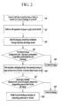
- FIGS. 2 and 3 illustrate a function of the discharge controller 111 and a discharging process of the power conversion system 100 through the smoothing condensers 9 and 33 according to one embodiment.
- the discharge controller 111 receives an inverter halt signal from the inverter circuit 4.
- the inverter halt signal may be received, for example, when an ignition key of the vehicle is turned off or the power conversion system 100 is halted by a fault (e.g., some defective condition of the vehicle and/or one of its systems) or an accident such as a car crash (Sp1).
- the discharge controller 111 receives a switch-off signal that indicates an off-operation of the electrical circuit switches 8 when the power conversion system 100 is halted (Sp2).
- the off-operation of the electrical circuit switches 8 may be performed by the discharge controller 111.
- the discharge controller 111 After the inverter halt signal and the switch-off signal are received, the discharge controller 111 starts discharging the smoothing condensers 9 and 33 through the exclusive discharge circuit 12 (Sp3). For example, the discharge controller 111 simultaneously outputs a driving command signal (control signal) for turning on only the upper arm 31a of the voltage booster circuit 3, while outputting a driving command signal (control signal) for turning on the semiconductor switch element 122 to the driving circuit 123 of the exclusive discharge circuit 12. Accordingly, the charges in the first and second smoothing condensers 9 and 33 are discharged through the resistor 121 of the exclusive discharge circuit 12.
- the second smoothing condenser 33 has the greater inter-terminal voltage, and is discharged first through the exclusive discharge circuit 12.
- the first and second smoothing condensers 9 and 33 are discharged together after the inter-terminal voltage of the second smoothing condenser 33 is equal to that of first smoothing condenser 9.
- the discharge controller 111 receives the voltage detection signals from the respective voltage detection units 13 and 14 at the same time, when starting discharge through the exclusive discharge circuit 12.
- the discharge controller 111 determines whether or not a fault of the exclusive discharge circuit 12 exists depending on whether the inter-terminal voltage can be discharged to the target value Vc within the fault detection time Tc (Sp4). For example, the discharge controller 111 detects a fault of the exclusive discharge circuit 12 if the inter-terminal voltage of the second smoothing condenser 33 is not discharged to the target value Vc within the fault detection time Tc.
- the discharge controller 111 continues discharging if the inter-terminal voltage of the second smoothing condenser 33 can be discharged to the target value Vc within the fault detection time Tc, e.g., if the fault of the exclusive discharge circuit 12 has not occurred.
- the discharge controller 111 terminates discharging when the inter-terminal voltage reaches a predetermined safety voltage, e.g., the target value Vd, within an allowed discharge time Td (Sp5).
- the discharge controller 111 starts discharging the smoothing condensers 9 and 33 through the voltage booster circuit 3 if the inter-terminal voltage of the second smoothing condenser 33 is not discharged to the target value Vc within the fault detection time Tc, e.g., if a fault of the exclusive discharge circuit 12 has occurred (Sp6).
- the discharge controller 111 outputs a driving command signal (control signal) for simultaneously turning on the upper and lower arms 31a and 31b of the voltage booster circuit 3 and/or the upper and lower arms 41a and 41b of the inverter circuit 4. Accordingly, the stored charges in the second and first smoothing condensers 33 and 9 are discharged through parasitic resistance components of the upper and lower arms 31a and 31b and/or the upper and lower arms 41a and 41b.
- the second smoothing condenser 33 has the greater inter-terminal voltage and is discharged first through the voltage booster circuit 3.
- the first and second smoothing condensers 9 and 33 are discharged together after the inter-terminal voltage of the second smoothing condenser 33 is equal to that of the first smoothing condenser 9.
- Discharging through the upper and lower arms 41a and 41b of the inverter circuit 4 may simultaneously turn on all the upper and lower arms 41a and 41b of the three-phase bridge circuits 4u, 4v, and 4w, or the upper and lower arms 41a and 41b of any single phase bridge circuit.
- the discharge controller 111 receives the voltage detection signals from the respective voltage detection units 13 and 14, and detects whether or not a fault of discharging through the voltage booster circuit 3 and the inverter circuit 4 occurs depending on whether the inter-terminal voltage can be discharged to a target value Vc' within a fault detection time Tc' (Sp7).
- the fault detection time Tc' and the target value Vc' of discharging through the voltage booster circuit 3 and the inverter circuit 4 may be the same as or different from the fault detection time Tc and the target value Vc of the discharging through the exclusive discharge circuit 12.
- the discharge controller 111 detects the fault of the discharging through the voltage booster circuit 3 and the inverter circuit 4 depending on whether or not the inter-terminal voltage of the first smoothing condenser 9 can be discharged to a target value Vc1' within a fault detection time Tc1', and whether or not the inter-terminal voltage of the second smoothing condenser 33 can be discharged to a target value Vc2' within a fault detection time Tc2'.
- the discharge controller 111 continues discharging if the inter-terminal voltages of the smoothing condensers 9 and 33 can be discharged to the target value Vc' within the fault detection time Tc', e.g., if a fault of discharging through the voltage booster circuit 3 has not occurred.
- the discharge controller 111 terminates discharging after being discharged to the target value Vd within the allowed discharge time Td, e.g., the safety voltage (Sp8).
- the fault detection time Tc of the exclusive discharge circuit 12, the fault detection time Tc' of the discharging through the voltage booster circuit 3, and the discharging time through the voltage booster circuit 3 may add to a value less than the allowed discharge time Td.
- the discharge controller 111 directly performs discharging through the voltage booster circuit 3, while omitting detecting of the exclusive discharge circuit 12.
- the discharge controller 111 terminates discharging and notifies the fault state of the discharging function of the power conversion system 100, e.g., to a driver via a display, a speaker, etc. in the vehicle (Sp9).
- the discharge controller 111 detects a fault of the exclusive discharge circuit 12
- the discharge controller 111 allows the stored charges of the smoothing condensers 9 and 33 to be discharged through the exclusive discharge circuit 12 as usual if the fault of the exclusive discharge circuit 12 does not occur.
- the respective inter-terminal voltages of the smoothing condensers 9 and 33 can be discharged to a safe value within a predetermined time.
- the discharge controller 111 can simultaneously turn on the upper and lower arms 31a and 31b of the voltage booster circuit 3 and the upper and lower arms 41a and 41b of the inverter circuit 4.
- the stored charges in the smoothing condensers 9 and 33 are discharged through the parasitic resistance components of the voltage booster circuit 3 and the inverter circuit 4, and the inter-terminal voltages of the smoothing condensers 9 and 33 are decreased to the predetermined safe value within the predetermined time.
- the upper and lower arms 31a and 31b of the voltage booster circuit 3 and the upper and lower arms 41a and 41b are used, no additional circuit or part is required. Also, the stored charges of the smoothing condensers 9 and 33 can be discharged through the existing circuit, and the discharging function of the smoothing condensers 9 and 33 can be redundantly provided.
- the discharge controller 111 may discharge the stored charges from the smoothing condensers 9 and 33 through a maximum of four redundant discharge devices or paths.
- the stored charges may be discharged through (1) a redundant discharge device or path using the upper and lower arms 31a and 31b of the voltage booster circuit 3, (2) the upper and lower arms 41a and 41b of the bridge circuit 4u of the inverter circuit 4, (3) the upper and lower arms 41a and 41b of the bridge circuit 4v of the inverter circuit 4, and (4) the upper and lower arms 41a and 41b of the bridge circuit 4w of the inverter circuit 4.
- the discharge controller 111 may detect a fault of the exclusive discharge circuit 12 using the inter-terminal voltage of the second smoothing condenser 33, using the inter-terminal voltage of the first smoothing condenser 9, or both of the inter-terminal voltages of the first and second smoothing condensers 9 and 33. In this case, the discharge controller 111 may detect a fault after the inter-terminal voltage of the first smoothing condenser 9 is equal to that of the second smoothing condenser 33.
- the motor driving power system S2 may have a configuration in which the voltage booster circuit 3 is not included and the DC main power supply 2 is directly connected to the inverter circuit 4.
- the discharge controller 111 may simultaneously turn on the upper and lower arms 31a and 31b of the voltage booster circuit 3 and the upper and lower arms 41 a and 41b of the inverter circuit 4.
- the stored charges in the smoothing condensers 9 and 33 are discharged through the parasitic resistance components of the voltage booster circuit 3 and the inverter circuit 4.
- the inter-terminal voltages of the smoothing condensers 9 and 33 may be decreased to a predetermined safe value within the predetermined time.
- the motor driving power system S2 may be configured such that it is not installed with the exclusive discharge circuit 12.
- the discharge controller 111 performs the control sequences after operation Sp6 while omitting operations Sp1 to Sp5. Accordingly, even if the motor driving power system S2 is not installed with the exclusive discharge circuit 12, the discharge controller 111 may discharge the stored charges from the smoothing condensers 9 and 33.
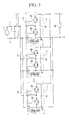
- a plurality of voltage booster circuits 3 may be simultaneously connected in parallel with the DC main power supply 2, while each of the parallel-connected voltage booster circuits 3 may be independently provided with the driving circuit 34.
- the control circuit 11 outputting the control signal to the driving circuit 34 may be configured to halt the operation of the faulty voltage booster circuit 3, set a power control value according to the number of the remaining normal voltage booster circuits 3, and control the remaining normal voltage booster circuits 3 and the inverter circuit 4 according to the power control value. Because the plurality of voltage booster circuits 3 are installed in parallel, redundancy of the power conversion system 100 may be improved.
- the plurality of voltage booster circuits 3 are installed in parallel.
- the current may be distributed to each of the voltage booster circuits 3.
- efficiency enhancement such as the high-efficiency voltage booster circuits 3
- reduced size such as the high-efficiency voltage booster circuits 3
- longer lifespan of the parts may be achieved.
- the discharge controller 111 may set a power limiting value according to the number of remaining normal voltage booster circuits 3, and may control the remaining normal voltage booster circuits 3 and the inverter circuit 4 according to the power limit value.
- power-limited operation of the motor generator 5 may continue to charge regenerative power to the DC main power supply 2, the auxiliary device 6 of the vehicle, and the DC auxiliary power supply 7 even after some of the voltage booster circuits 3 fail. Accordingly, a limp-home mode system may be implemented, thereby making it possible to safely evacuate a driver by allowing the driver to take the vehicle to a repair shop.
- each smoothing condenser 33 may function as the smoothing condenser to the input terminals of inverter circuit 4.
- a ripple current may be reduced by the current distribution in charging/discharging the smoothing condenser 33 when receiving/transmitting power from/to the inverter circuit 4. Also, a reduced size of the smoothing condenser 33 or reduction in power loss thereof may be achieved, and performance may be improved.
- the number of redundant discharge devices or paths may be increased according to the increased number of voltage booster circuits 3.
- discharge circuits may be used in an electric vehicle to forcibly discharge the stored charges in a smoothing condenser through a resistor.
- an exclusive discharge circuit connects a resistor and a semiconductor switch element, which is connected between the electrodes of a main circuit.
- a switch for opening/closing an electrical circuit connected to output terminals of a DC main power supply is then blocked.
- a switch element of a discharge circuit is turned on to forcibly discharge stored charge of the smoothing condenser through a resistor.
- the forced discharge of the smoothing condenser is not performed and the inter-terminal voltage of the smoothing condenser may maintain an unsafe, high-voltage level, even after the predetermined time has elapsed.
- an electric vehicle power conversion system includes a discharge circuit that can reliably discharge stored charges from a smoothing condenser, even when a primary discharge circuit fails.
Landscapes
- Engineering & Computer Science (AREA)
- Power Engineering (AREA)
- Transportation (AREA)
- Mechanical Engineering (AREA)
- Life Sciences & Earth Sciences (AREA)
- Sustainable Development (AREA)
- Sustainable Energy (AREA)
- Inverter Devices (AREA)
- Electric Propulsion And Braking For Vehicles (AREA)
- Dc-Dc Converters (AREA)
Abstract
Description
- The invention relates to an electric vehicle power conversion system.
- Various types of power conversion systems have been developed for electric vehicles. One type of power conversion system performs a retrogressive operation, which involves boosting a DC voltage from a main power supply, converting the DC voltage to an AC voltage, and outputting the AC voltage to a motor generator. This system may also perform a regenerative operation, which involves supplying regenerative power of the motor generator to the main power supply, auxiliary devices (e.g., electric power steering, an air conditioner, an ECU, etc.) of an electric vehicle, and/or a DC auxiliary power supply.
- In such a system, when power conversion stops (e.g., as a result of an off-operation of an ignition key, a fault, or a vehicle collision or other accident), charges stored in a smoothing condenser, installed between electrodes located between a main circuit, may be forcibly (e.g., actively) discharged within a predetermined time. This forced discharge is performed so that an inter-terminal voltage of the smoothing condenser decreases to a safe voltage level.
- In order to perform this operation, the switch element of a discharge circuit may be turned on to forcibly discharge the stored charges of the smoothing condenser through a resistor. However, when the discharge circuit fails, the forced discharge of the smoothing condenser is not performed and the inter-terminal voltage of the smoothing condenser may maintain an unsafe, high-voltage level, even after the predetermined time has elapsed.
- The present invention sets out to provide a solution to the above-mentioned problems of the prior art.
- In accordance with one embodiment of the invention, an electric vehicle power conversion system includes a motor driving power system to output a DC voltage from a DC main power supply to a motor generator through an inverter circuit; and a control circuit to control the motor driving power system, wherein: the motor driving power system is to connect a smoothing condenser for smoothing the DC voltage, a resistor, and a semiconductor switch element in series, the motor driving power system includes an exclusive discharge circuit to discharge stored charge from the smoothing condenser, the control circuit includes a discharge controller to simultaneously turn on a first set of upper and lower arms when a failure of the exclusive discharge circuit is detected, the upper and lower arms including power semiconductors of the inverter circuit, and the discharge controller to discharge the stored charge from the smoothing condenser through parasitic resistance components of the upper and lower arms.
- The discharge controller may detect the failure of the exclusive discharge circuit depending on whether or not an inter-terminal voltage of the smoothing condenser is able to be discharged to a target voltage within a predetermined time.
- The motor driving power system may output the DC voltage from the DC main power supply to the motor generator through a voltage booster circuit and the inverter circuit; the discharge controller may simultaneously turn on a second set of upper and lower arms when a failure of the exclusive discharge circuit is detected, the first set of upper and lower arms including serial-connected power semiconductors of the voltage booster circuit, or to simultaneously turn on the first set of upper and lower arms including power semiconductors of the inverter circuit, and the discharge controller may discharge the stored charge from the smoothing condenser through parasitic resistance components of the second set of upper and lower arms of the voltage booster circuit or the first set of upper and lower arms of the inverter circuit.
- The smoothing condenser may include a first smoothing condenser between the DC main power supply and the voltage booster circuit, and a second smoothing condenser between the voltage booster circuit and the inverter circuit.
- In accordance with another embodiment, an apparatus includes an input coupled to a circuit; and a controller to control discharge of a smoothing condenser based on at least one signal received through the input, the at least one signal indicating failure of a discharge circuit configured to discharge the smoothing condenser, the controller to control discharge of stored charge in the smoothing condenser through parasitic resistance components of a power system which includes the smoothing condenser.
- The failure of the discharge circuit may prevent the discharge circuit from discharging the smoothing condenser. The input may be an input of the controller. The controller may detect the failure from the signal when an inter-terminal voltage of the smoothing condenser is unable to be discharged to a target voltage within a predetermined time. The parasitic resistance components may be included in a voltage booster circuit.
- The controller may control discharge of the stored charge in the smoothing capacitor independently from the discharge circuit having the failure. The controller may control discharge of the stored charge in the smoothing capacitor along a signal path that bypasses the discharge circuit. The power system may be a motor driving power system of a vehicle. The circuit may be a detector or an inverter.
- In accordance with another embodiment, an apparatus includes a first discharge circuit; a second discharge circuit; and a controller to control discharge of a charge storage device through one of the first discharge circuit or the second discharge circuit, wherein the controller is to control discharge of the charge storage device through the first discharge circuit when the first discharge circuit does not have a failure and is to control discharge of the charge storage device through the second discharge circuit when the first discharge circuit has a failure, and wherein the charge storage device is discharged through the second discharge circuit along a path that bypasses the first discharge circuit.
- The charge storage device may be a smoothing condenser. The controller may determine that the second discharge circuit has a failure when an inter-terminal voltage of the smoothing condenser is unable to be discharged through the first discharge circuit to a target voltage within a predetermined time.
- The second discharge circuit may include parasitic resistance components of a power system, and the charge storage device may be discharged through the parasitic resistance components of the second discharge circuit when the first discharge circuit has a failure. The parasitic resistance components may be included in a voltage booster circuit.
- The controller may detect the failure of the first discharge circuit when an inter-terminal voltage of the smoothing condenser is unable to be discharged to a target voltage within a predetermined time. The charge storage device may be coupled to a motor of an electric vehicle.
- At least some of the above and other features of the invention are set out in the claims.
- Embodiments of the invention will be made more apparent to those of skill in the art by describing them in detail with reference to the attached drawings in which:
-
FIG. 1 illustrates an embodiment of an electric vehicle power conversion system; -
FIG. 2 illustrates an embodiment of a discharge process performed by a discharge controller; -
FIG. 3 illustrates an embodiment of a discharge process through an auxiliary device power system; -
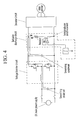
FIG. 4 illustrates a discharge process through one type of exclusive discharge circuit; and -
FIG. 5 illustrates an embodiment including a plurality of voltage booster circuits connected in parallel. - Embodiments of the invention are described more fully hereinafter with reference to the accompanying drawings; however, the invention may be embodied in different forms and should not be construed as limited to the embodiments set forth herein. Rather, these embodiments are provided so that this disclosure will be thorough, and convey implementations thereof to those skilled in the art.
- In the drawing figures, the dimensions of layers and regions may be exaggerated for clarity of illustration. It will also be understood that when a layer or element is referred to as being "on" another layer or substrate, it can be directly on the other layer or substrate, or intervening layers may also be present. Further, it will be understood that when a layer is referred to as being "under" another layer, it can be directly under, and one or more intervening layers may also be present. In addition, it will also be understood that when a layer is referred to as being "between" two layers, it can be the only layer between the two layers, or one or more intervening layers may also be present. Like reference numerals refer to like elements throughout.
- Also, when it is described that an element is "coupled" to another element, the element may be "directly coupled" to the other element or "electrically coupled" to the other element through a third element.
-
FIG. 1 illustrates an embodiment of apower conversion system 100, which, for example, may be installed in an electrically driven vehicle, such as a hybrid vehicle or an electric vehicle. The power conversion system may retrogressively or regeneratively drive amotor generator 5. a parallel or split-type (serial-parallel type) or a serial type may be used as a type of the hybrid vehicle using themotor generator 5. - The
power conversion system 100 performs a retrogressive operation and a regenerative operation. The retrogressive operation involves boosting a DC voltage from a DC main power supply 2 through a voltage booster circuit 3, converting the DC voltage into a three-phase AC voltage through aninverter circuit 4, and then outputting the AC voltage to themotor generator 5. The regenerative operation involves supplying regenerated power from themotor generator 5 through theinverter circuit 4 and the voltage booster circuit 3 to the DC main power supply 2, anauxiliary device 6, and/or a DCauxiliary power supply 7. - For example, the
power conversion system 100 may include the DC main power supply 2 (e.g., a 48 V lithium-ion battery), electrical circuit switches (e.g., DC contactors) 8 for closing/opening electrical circuits respectively connected to output terminals of the DC main power supply 2, a first smoothing condenser (e.g., DC link condenser) 9 between the switches 8, an auxiliary device power system S1 connected via the first smoothing condenser 9 and supplying power to each ofauxiliary devices 6 of the vehicle (e.g., electrically-controlled power steering, an air-conditioner, an ECU) and the DC auxiliary power supply 7 (e.g., a 12 V/24 V battery), and a motor driving power system S2 connected in parallel with the auxiliary devicepower system S 1 via the first smoothing condenser 9 and configured to retrogressively or regeneratively drive themotor generator 5. The first smoothing condenser 9 may be included in the motor driving power system S2. - The auxiliary device power system S1 includes a DC/
DC converter 10. The respectiveauxiliary devices 6 and the DCauxiliary power supply 7 are connected in parallel at output terminals of the DC/DC converter 10. - The motor driving power system S2 includes the voltage booster circuit 3 for voltage-converting the DC voltage from the DC main power supply 2. The
inverter circuit 4 converts a DC voltage output from the voltage booster circuit 3 to an AC voltage for output to themotor generator 5. - The voltage booster circuit 3 includes
power semiconductors reactor 32, and asecond smoothing condenser 33. The voltage booster circuit 3 includes upper andlower arms inverter circuit 4 is connected to a semiconductor terminal (e.g., a collector terminal or drain terminal) of theupper arm 31a. A negative terminal of the DC main power supply 2 is connected to a semiconductor terminal (e.g., an emitter terminal or source terminal) of thelower arm 31b. - The
second smoothing condenser 33 is connected between the semiconductor terminals of the upper andlower arms condenser 33 may be connected in parallel with the upper andlower arms - One terminal of the
reactor 32 is connected between the other terminal of theupper arm 31a (emitter terminal or source terminal) and the other terminal of thelower arm 31 b (collector terminal or drain terminal), e.g., at a serial connection point therebetween. The other terminal thereactor 32 may be connected to the positive terminal of the DC main power supply 2. Alternatively, the upper andlower arms - The voltage booster circuit 3 is provided with a driving
circuit 34 for driving the upper andlower arms circuit 34 allows the upper andlower arms reactor 32 is charged and discharged to deliver power in a retrogressive (boosting) direction or regenerative (bucking) direction. The drivingcircuit 34 receives a driving command signal (control signal) from acontrol circuit 11. - The
second smoothing condenser 33 is installed in the voltage booster circuit 3 and functions as a smoothing condenser at input terminals of theinverter circuit 4. For example, thesecond smoothing condenser 33 is commonly used by the voltage booster circuit 3 and theinverter circuit 4. - The
inverter circuit 4 includes three-phase bridge circuits circuit 42. The three-phase bridge circuits lower arms circuit 42 drives the upper andlower arms bridge circuits - The upper and
lower arms circuit 42 receives a driving command signal (control signal) from acontrol circuit 11. The auxiliary device power system S1 and the motor driving power system S2 are controlled by thecontrol circuit 11. - To perform the retrogressive/regenerative power control required for operation of the electric vehicle, the
control circuit 11 generates driving command signals for each power semiconductor, while taking an optimal power linkage to the voltage booster circuits 3 and theinverter circuit 4 based on a required operation command from an overall controller (e.g., upper ECU). Thecontrol circuit 11 may transfer the driving command signals for the corresponding power semiconductor to each driving circuit as a switching command. - Accordingly,
power conversion system 100 performs a retrogressive operation of boosting the DC voltage of the DC main power supply 2 through the voltage booster circuit 3, converting the DC voltage to an AC voltage through theinverter circuit 4, and outputting the AC voltage to themotor generator 5. Thepower conversion system 100 performs a regenerative operation of supplying the regenerative power of themotor generator 5 to the DC main power supply 2, theauxiliary device 6 of the vehicle, and the DCauxiliary power supply 7 via theinverter circuit 4 and voltage booster circuit 3. - The
control circuit 11 may be configured to be physically divided to respectively correspond to the voltage booster circuit 3 and theinverter circuit 4, or may be commonly used and integrally formed to reduce the number of parts for cost reduction. - In the
power conversion system 100 of the present embodiment, the motor driving power system S2 includes anexclusive discharge circuit 12 for discharging stored charges from each of the smoothingcondensers 9 and 33.Reference numeral 15 illustrated inFIG. 1 refers to a self-discharge resistor. - The
exclusive discharge circuit 12 connects aresistor 121 and a semiconductor switch element 122 (e.g., an IGBT, a MOSFET, etc.) in series, and is disposed between main circuit electrodes of thepower conversion system 100 while being connected therebetween. For example, theexclusive discharge circuit 12 may be disposed between the voltage booster circuit 3 and theinverter circuit 4, and may be installed between the main circuit electrodes while being connected therebetween. - The
exclusive discharge circuit 12 includes a driving circuit 123 for driving thesemiconductor switch element 122. The driving circuit 123 turns on thesemiconductor switch element 122 to perform a discharge function of theexclusive discharge circuit 12. Also, the drivingcircuit 122 receives a driving command signal (control signal) from thecontrol circuit 11. - The
control circuit 11 of the present embodiment includes adischarge controller 111 for discharging the stored charges from the smoothingcondensers 9 and 33 through theexclusive discharge circuit 12 or voltage booster circuit 3. Thecontrol circuit 11 may be an exclusive or general purpose computer circuit including a CPU, a memory, an I/O interface, an AD converter, etc., and may control the functions of thedischarge controller 111 depending on a control program stored in a memory. - For example, the
discharge controller 111 may perform a fault detection function for detecting the fault of theexclusive discharge circuit 12. Thedischarge controller 111 may change the discharge circuit for the stored charges in the smoothingcondensers 9 and 33 to theexclusive discharge circuit 12 and the voltage booster circuit 3, depending on whether a fault of theexclusive discharge circuit 12 occurs. - In terms of signaling, the
discharge controller 111 may receive a signal indicating a halt of the power conversion system 100 (e.g., an inverter halt signal indicating a halt of the inverter circuit 4), may simultaneously receive a switch-off signal indicating an off-state (blocked) of the electrical switch 8, and may start a discharge process of the smoothingcondensers 9 and 33. - The
discharge controller 111 receives a first voltage detection signal from afirst voltage detector 13 located between the electrical circuit switches 8 and the voltage booster circuit 3. Thefirst voltage detector 13 detects an inter-terminal voltage of the first smoothing condenser 9. - Simultaneously, the
discharge controller 111 receives a second voltage detection signal from asecond voltage detector 14 located between the voltage booster circuit 3 and the inverter circuit 4d. Thesecond voltage detector 14 detects an inter-terminal voltage of thesecond smoothing condenser 33. - The
discharge controller 111 uses the first and second voltage detection signals to detect whether or not a fault of theexclusive discharge circuit 12 exists. Thedischarge controller 111 discharges the smoothingcondensers 9 and 33 through theexclusive discharge circuit 12 if a fault of theexclusive discharge circuit 12 has not occurred, and discharges the smoothingcondensers 9 and 33 through the upper andlower arms lower arms inverter circuit 4 if the fault of theexclusive discharge circuit 12 has occurred. - Hereinafter, an embodiment of a method in which the
discharge controller 111 detects the fault of theexclusive discharge circuit 12 will be described. Thedischarge controller 111 detects whether or not a fault exists in theexclusive discharge circuit 12 based on a fault detection time Tc and a target value Vc. The fault detection time Tc indicates a predetermined time after a preset forced discharge starts. The target value Vc is a target value of the inter-terminal voltage of thesecond smoothing condenser 33 after the fault detection time Tc elapses. Thedischarge controller 111 detects that a fault of theexclusive discharge circuit 12 exists if discharge to the target value Vc does not occur within the fault detection time Tc. - Because the inter-terminal voltage of the
second smoothing condenser 33 is greater than that of the first smoothing condenser 9, and the inter-terminal voltage of thesecond smoothing condenser 33 decreases first by the forced discharge start, the inter-terminal of thesecond smoothing condenser 33 may be used to detect a fault. - For example, the inter-terminal voltages of the
second smoothing condenser 33 may be detected at predetermined time intervals (e.g., 0.1 second intervals) until the fault detection time Tc elapses. A fault may be determined to exist depending on whether the inter-terminal voltage can be discharged to the target value Vc. - In this case, the target value Vc of the inter-terminal voltage after the fault detection time Tc elapses may be determined by an inter-terminal voltage vs. discharge-time characteristic curve of the
second smoothing condenser 33 resulting from the forced discharge start. Alternatively, the fault detection of theexclusive discharge circuit 12 may be determined from variations such as a decreasing rate, a decreasing amount, or the like, of the inter-terminal voltage in the fault detection time Tc. -
FIGS. 2 and3 illustrate a function of thedischarge controller 111 and a discharging process of thepower conversion system 100 through the smoothingcondensers 9 and 33 according to one embodiment. - First, the
discharge controller 111 receives an inverter halt signal from theinverter circuit 4. The inverter halt signal may be received, for example, when an ignition key of the vehicle is turned off or thepower conversion system 100 is halted by a fault (e.g., some defective condition of the vehicle and/or one of its systems) or an accident such as a car crash (Sp1). - In addition, the
discharge controller 111 receives a switch-off signal that indicates an off-operation of the electrical circuit switches 8 when thepower conversion system 100 is halted (Sp2). Alternatively, the off-operation of the electrical circuit switches 8 may be performed by thedischarge controller 111. - After the inverter halt signal and the switch-off signal are received, the
discharge controller 111 starts discharging the smoothingcondensers 9 and 33 through the exclusive discharge circuit 12 (Sp3). For example, thedischarge controller 111 simultaneously outputs a driving command signal (control signal) for turning on only theupper arm 31a of the voltage booster circuit 3, while outputting a driving command signal (control signal) for turning on thesemiconductor switch element 122 to the driving circuit 123 of theexclusive discharge circuit 12. Accordingly, the charges in the first andsecond smoothing condensers 9 and 33 are discharged through theresistor 121 of theexclusive discharge circuit 12. - The
second smoothing condenser 33 has the greater inter-terminal voltage, and is discharged first through theexclusive discharge circuit 12. The first andsecond smoothing condensers 9 and 33 are discharged together after the inter-terminal voltage of thesecond smoothing condenser 33 is equal to that of first smoothing condenser 9. - The
discharge controller 111 receives the voltage detection signals from the respectivevoltage detection units exclusive discharge circuit 12. Thedischarge controller 111 determines whether or not a fault of theexclusive discharge circuit 12 exists depending on whether the inter-terminal voltage can be discharged to the target value Vc within the fault detection time Tc (Sp4). For example, thedischarge controller 111 detects a fault of theexclusive discharge circuit 12 if the inter-terminal voltage of thesecond smoothing condenser 33 is not discharged to the target value Vc within the fault detection time Tc. - The
discharge controller 111 continues discharging if the inter-terminal voltage of thesecond smoothing condenser 33 can be discharged to the target value Vc within the fault detection time Tc, e.g., if the fault of theexclusive discharge circuit 12 has not occurred. Thedischarge controller 111 terminates discharging when the inter-terminal voltage reaches a predetermined safety voltage, e.g., the target value Vd, within an allowed discharge time Td (Sp5). - In contrast, the
discharge controller 111 starts discharging the smoothingcondensers 9 and 33 through the voltage booster circuit 3 if the inter-terminal voltage of thesecond smoothing condenser 33 is not discharged to the target value Vc within the fault detection time Tc, e.g., if a fault of theexclusive discharge circuit 12 has occurred (Sp6). For example, as shown inFIG. 3 , thedischarge controller 111 outputs a driving command signal (control signal) for simultaneously turning on the upper andlower arms lower arms inverter circuit 4. Accordingly, the stored charges in the second and first smoothingcondensers 33 and 9 are discharged through parasitic resistance components of the upper andlower arms lower arms - The
second smoothing condenser 33 has the greater inter-terminal voltage and is discharged first through the voltage booster circuit 3. The first andsecond smoothing condensers 9 and 33 are discharged together after the inter-terminal voltage of thesecond smoothing condenser 33 is equal to that of the first smoothing condenser 9. - Discharging through the upper and
lower arms inverter circuit 4 may simultaneously turn on all the upper andlower arms phase bridge circuits lower arms - Similar to discharging through the
exclusive discharge circuit 12 described above, together with the starting discharging through the voltage booster circuit 3, thedischarge controller 111 receives the voltage detection signals from the respectivevoltage detection units inverter circuit 4 occurs depending on whether the inter-terminal voltage can be discharged to a target value Vc' within a fault detection time Tc' (Sp7). - The fault detection time Tc' and the target value Vc' of discharging through the voltage booster circuit 3 and the
inverter circuit 4 may be the same as or different from the fault detection time Tc and the target value Vc of the discharging through theexclusive discharge circuit 12. - The
discharge controller 111 detects the fault of the discharging through the voltage booster circuit 3 and theinverter circuit 4 depending on whether or not the inter-terminal voltage of the first smoothing condenser 9 can be discharged to a target value Vc1' within a fault detection time Tc1', and whether or not the inter-terminal voltage of thesecond smoothing condenser 33 can be discharged to a target value Vc2' within a fault detection time Tc2'. - The
discharge controller 111 continues discharging if the inter-terminal voltages of the smoothingcondensers 9 and 33 can be discharged to the target value Vc' within the fault detection time Tc', e.g., if a fault of discharging through the voltage booster circuit 3 has not occurred. Thedischarge controller 111 terminates discharging after being discharged to the target value Vd within the allowed discharge time Td, e.g., the safety voltage (Sp8). - The fault detection time Tc of the
exclusive discharge circuit 12, the fault detection time Tc' of the discharging through the voltage booster circuit 3, and the discharging time through the voltage booster circuit 3 may add to a value less than the allowed discharge time Td. - Once a fault of the
exclusive discharge circuit 12 is detected to perform the discharging through the voltage booster circuit 3, thedischarge controller 111 directly performs discharging through the voltage booster circuit 3, while omitting detecting of theexclusive discharge circuit 12. - In contrast, if one of the inter-terminal voltages of the first or
second smoothing condensers 9 and 33 is not discharged to the target value Vc' within the fault detection time Tc' (e.g., if the fault of the discharging through the voltage booster circuit 3 has occurred), thedischarge controller 111 terminates discharging and notifies the fault state of the discharging function of thepower conversion system 100, e.g., to a driver via a display, a speaker, etc. in the vehicle (Sp9). - According to this embodiment of the vehicle
power conversion system 100, because thedischarge controller 111 detects a fault of theexclusive discharge circuit 12, thedischarge controller 111 allows the stored charges of the smoothingcondensers 9 and 33 to be discharged through theexclusive discharge circuit 12 as usual if the fault of theexclusive discharge circuit 12 does not occur. Thus, the respective inter-terminal voltages of the smoothingcondensers 9 and 33 can be discharged to a safe value within a predetermined time. - In addition, when a fault of the
exclusive discharge circuit 12 has occurred, thedischarge controller 111 can simultaneously turn on the upper andlower arms lower arms inverter circuit 4. Thus, the stored charges in the smoothingcondensers 9 and 33 are discharged through the parasitic resistance components of the voltage booster circuit 3 and theinverter circuit 4, and the inter-terminal voltages of the smoothingcondensers 9 and 33 are decreased to the predetermined safe value within the predetermined time. - Because the upper and
lower arms lower arms condensers 9 and 33 can be discharged through the existing circuit, and the discharging function of the smoothingcondensers 9 and 33 can be redundantly provided. - In addition, when a fault of the
exclusive discharge circuit 12 has occurred, thedischarge controller 111 may discharge the stored charges from the smoothingcondensers 9 and 33 through a maximum of four redundant discharge devices or paths. - For example, the stored charges may be discharged through (1) a redundant discharge device or path using the upper and
lower arms lower arms bridge circuit 4u of theinverter circuit 4, (3) the upper andlower arms bridge circuit 4v of theinverter circuit 4, and (4) the upper andlower arms bridge circuit 4w of theinverter circuit 4. - In an alternative embodiment, the
discharge controller 111 may detect a fault of theexclusive discharge circuit 12 using the inter-terminal voltage of thesecond smoothing condenser 33, using the inter-terminal voltage of the first smoothing condenser 9, or both of the inter-terminal voltages of the first andsecond smoothing condensers 9 and 33. In this case, thedischarge controller 111 may detect a fault after the inter-terminal voltage of the first smoothing condenser 9 is equal to that of thesecond smoothing condenser 33. - Alternatively, the motor driving power system S2 may have a configuration in which the voltage booster circuit 3 is not included and the DC main power supply 2 is directly connected to the
inverter circuit 4. In this case, when a fault of theexclusive discharge circuit 12 has occurred, thedischarge controller 111 may simultaneously turn on the upper andlower arms lower arms inverter circuit 4. As a result, the stored charges in the smoothingcondensers 9 and 33 are discharged through the parasitic resistance components of the voltage booster circuit 3 and theinverter circuit 4. - Accordingly, even if the voltage booster circuit 3 is not included, the inter-terminal voltages of the smoothing
condensers 9 and 33 may be decreased to a predetermined safe value within the predetermined time. - Alternatively, the motor driving power system S2 may be configured such that it is not installed with the
exclusive discharge circuit 12. In this case, thedischarge controller 111 performs the control sequences after operation Sp6 while omitting operations Sp1 to Sp5. Accordingly, even if the motor driving power system S2 is not installed with theexclusive discharge circuit 12, thedischarge controller 111 may discharge the stored charges from the smoothingcondensers 9 and 33. - Alternatively, as shown in
FIG. 5 , a plurality of voltage booster circuits 3 may be simultaneously connected in parallel with the DC main power supply 2, while each of the parallel-connected voltage booster circuits 3 may be independently provided with the drivingcircuit 34. - When a fault occurs in at least one of the voltage booster circuits 3, the
control circuit 11 outputting the control signal to the drivingcircuit 34 may be configured to halt the operation of the faulty voltage booster circuit 3, set a power control value according to the number of the remaining normal voltage booster circuits 3, and control the remaining normal voltage booster circuits 3 and theinverter circuit 4 according to the power control value. Because the plurality of voltage booster circuits 3 are installed in parallel, redundancy of thepower conversion system 100 may be improved. - In such a configuration without an alternator, because the plurality of voltage booster circuits 3 are installed in parallel, reliable power supply to the DC main power supply 2, the
auxiliary device 6 of theelectric vehicle 6, and the DCauxiliary power supply 7 are guaranteed. - Further, the plurality of voltage booster circuits 3 are installed in parallel. Thus, the current may be distributed to each of the voltage booster circuits 3. As a result, efficiency enhancement (such as the high-efficiency voltage booster circuits 3), reduced size, and longer lifespan of the parts may be achieved.
- When a fault occurs in at least one of the voltage booster circuits 3, the
discharge controller 111 may set a power limiting value according to the number of remaining normal voltage booster circuits 3, and may control the remaining normal voltage booster circuits 3 and theinverter circuit 4 according to the power limit value. As a result, power-limited operation of themotor generator 5 may continue to charge regenerative power to the DC main power supply 2, theauxiliary device 6 of the vehicle, and the DCauxiliary power supply 7 even after some of the voltage booster circuits 3 fail. Accordingly, a limp-home mode system may be implemented, thereby making it possible to safely evacuate a driver by allowing the driver to take the vehicle to a repair shop. - In addition, because the smoothing
condensers 33 are installed at output terminals of the parallel-connected voltage booster circuits 3, each smoothingcondenser 33 may function as the smoothing condenser to the input terminals ofinverter circuit 4. - As described above, because the smoothing
condensers 33 are installed at output terminals of the parallel-connected voltage booster circuits 3, a ripple current may be reduced by the current distribution in charging/discharging the smoothingcondenser 33 when receiving/transmitting power from/to theinverter circuit 4. Also, a reduced size of the smoothingcondenser 33 or reduction in power loss thereof may be achieved, and performance may be improved. - Alternatively, the number of redundant discharge devices or paths may be increased according to the increased number of voltage booster circuits 3.
- By way of summation and review, discharge circuits may be used in an electric vehicle to forcibly discharge the stored charges in a smoothing condenser through a resistor. For example, as illustrated in
FIG. 4 , an exclusive discharge circuit connects a resistor and a semiconductor switch element, which is connected between the electrodes of a main circuit. A switch for opening/closing an electrical circuit connected to output terminals of a DC main power supply is then blocked. Then, a switch element of a discharge circuit is turned on to forcibly discharge stored charge of the smoothing condenser through a resistor. - However, when the discharge circuit fails, the forced discharge of the smoothing condenser is not performed and the inter-terminal voltage of the smoothing condenser may maintain an unsafe, high-voltage level, even after the predetermined time has elapsed.
- In accordance with one or more of the aforementioned embodiments, an electric vehicle power conversion system includes a discharge circuit that can reliably discharge stored charges from a smoothing condenser, even when a primary discharge circuit fails.
- Example embodiments have been disclosed herein, and although specific terms are employed, they are used and are to be interpreted in a generic and descriptive sense only and not for purpose of limitation. In some instances, as would be apparent to one of skill in the art as of the filing of the present application, features, characteristics, and/or elements described in connection with a particular embodiment may be used singly or in combination with features, characteristics, and/or elements described in connection with other embodiments unless otherwise indicated. Accordingly, it will be understood by those of skill in the art that various changes in form and details may be made without departing from the scope of the present invention as set forth in the following claims.
Claims (20)
- An electric vehicle power conversion system, comprising:a motor driving power system to output a DC voltage from a DC main power supply to a motor generator through an inverter circuit; anda control circuit for controlling the motor driving power system, wherein:the motor driving power system includes a smoothing condenser for smoothing the DC voltage, a resistor, and a semiconductor switch element connected in series,the motor driving power system includes an exclusive discharge circuit to discharge stored charge from the smoothing condenser,the control circuit includes a discharge controller to simultaneously turn on a first set of upper and lower arms when a failure of the exclusive discharge circuit is detected, the upper and lower arms including power semiconductors of the inverter circuit, andthe discharge controller is adapted to discharge the stored charge from the smoothing condenser through parasitic resistance components of the upper and lower arms.
- A system as claimed in claim 1, wherein the discharge controller is adapted to detect the failure of the exclusive discharge circuit depending on whether or not an inter-terminal voltage of the smoothing condenser is able to be discharged to a target voltage within a predetermined time.
- A system as claimed in claim 1 or 2, wherein:the motor driving power system is adapted to output the DC voltage from the DC main power supply to the motor generator through a voltage booster circuit and the inverter circuit;the discharge controller is adapted to simultaneously turn on a second set of upper and lower arms when a failure of the exclusive discharge circuit is detected, the second set of upper and lower arms including serial-connected power semiconductors of the voltage booster circuit, or to simultaneously turn on the first set of upper and lower arms including power semiconductors of the inverter circuit, andthe discharge controller is adapted to discharge the stored charge from the smoothing condenser through parasitic resistance components of the second set of upper and lower arms of the voltage booster circuit or the first set of upper and lower arms of the inverter circuit.
- A system as claimed in claim 3, wherein the smoothing condenser includes a first smoothing condenser between the DC main power supply and the voltage booster circuit, and a second smoothing condenser between the voltage booster circuit and the inverter circuit.
- An apparatus, comprising:an input coupled to a circuit; anda controller for controlling discharge of a smoothing condenser based on at least one signal received through the input, the at least one signal indicating failure of a discharge circuit configured to discharge the smoothing condenser, the controller being adapted to control discharge of stored charge in the smoothing condenser through parasitic resistance components of a power system which includes the smoothing condenser.
- Apparatus as claimed in claim 5, adapted such that the failure of the discharge circuit prevents the discharge circuit from discharging the smoothing condenser.
- Apparatus as claimed in claim 5 or 6, wherein the input is an input of the controller.
- Apparatus as claimed in claim 5, 6 or 7 wherein the controller is adapted to detect the failure from the signal when an inter-terminal voltage of the smoothing condenser is unable to be discharged to a target voltage within a predetermined time.
- Apparatus as claimed in one of claims 5 to 8, wherein the parasitic resistance components are included in a voltage booster circuit or in a inverter circuit.
- Apparatus as claimed in one of claims 5 to 9, wherein the controller is adapted to control discharge of the stored charge in the smoothing condenser independently from the discharge circuit having the failure.
- Apparatus as claimed in one of claims 5 to 10, wherein the controller is adapted to control discharge of the stored charge in the smoothing condenser along a signal path that bypasses the discharge circuit.
- Apparatus as claimed in one of claims 5 to 11, wherein the power system is a motor driving power system of a vehicle.
- Apparatus as claimed in one of claims 5 to 12, wherein the circuit is a detector or an inverter.
- An apparatus, comprising:a first discharge circuit;a second discharge circuit; anda controller controlling discharge of a charge storage device through one of the first discharge circuit or the second discharge circuit, wherein the controller is adapted to control discharge of the charge storage device through the first discharge circuit when the first discharge circuit does not have a failure and to control discharge of the charge storage device through the second discharge circuit when the first discharge circuit has a failure, and wherein the charge storage device is discharged through the second discharge circuit along a path that bypasses the first discharge circuit.
- Apparatus as claimed in claim 14, wherein the charge storage device is a smoothing condenser.
- Apparatus as claimed in claim 15, wherein the controller is adapted to determine that the first discharge circuit has a failure when an inter-terminal voltage of the smoothing condenser is unable to be discharged through the first discharge circuit to a target voltage within a predetermined time.
- Apparatus as claimed in claim 15 or 16, wherein the controller is adapted to detect the failure of the first discharge circuit when an inter-terminal voltage of the smoothing condenser is unable to be discharged to a target voltage within a predetermined time.
- Apparatus as claimed in claim 14, 15, 16 or 17 wherein the second discharge circuit includes parasitic resistance components of a power system, and wherein the charge storage device is discharged through the parasitic resistance components of the second discharge circuit when the first discharge circuit has a failure.
- Apparatus as claimed in claim 18, wherein the parasitic resistance components are included in a voltage booster circuit.
- Apparatus as claimed in one of claims 14 to 19, wherein the charge storage device is coupled to a motor of an electric vehicle.
Applications Claiming Priority (2)
| Application Number | Priority Date | Filing Date | Title |
|---|---|---|---|
| JP2013208866A JP6339785B2 (en) | 2013-10-04 | 2013-10-04 | Electric vehicle power conversion system |
| KR20140041286A KR20150040195A (en) | 2013-10-04 | 2014-04-07 | Power conversion system for electric vehicles |
Publications (2)
| Publication Number | Publication Date |
|---|---|
| EP2860060A2 true EP2860060A2 (en) | 2015-04-15 |
| EP2860060A3 EP2860060A3 (en) | 2016-04-13 |
Family
ID=51726343
Family Applications (1)
| Application Number | Title | Priority Date | Filing Date |
|---|---|---|---|
| EP14187640.9A Ceased EP2860060A3 (en) | 2013-10-04 | 2014-10-03 | Electric vehicle power conversion system |
Country Status (3)
| Country | Link |
|---|---|
| US (1) | US10202042B2 (en) |
| EP (1) | EP2860060A3 (en) |
| CN (1) | CN104512274B (en) |
Cited By (2)
| Publication number | Priority date | Publication date | Assignee | Title |
|---|---|---|---|---|
| EP3385109A1 (en) * | 2017-04-06 | 2018-10-10 | Audi Ag | Safety device for reversible switching off at least one electrical component of a motor vehicle, motor vehicle with a safety device and method for operating a safety device |
| WO2020224700A1 (en) * | 2019-05-07 | 2020-11-12 | Schaeffler Technologies AG & Co. KG | Multiphase voltage transformer for a supply network and method for powering down an intermediate circuit voltage of this supply network |
Families Citing this family (23)
| Publication number | Priority date | Publication date | Assignee | Title |
|---|---|---|---|---|
| RU2709628C2 (en) * | 2015-03-17 | 2019-12-19 | Филипс Лайтинг Холдинг Б.В. | Exciter with at least four different states |
| DE102015110423B4 (en) * | 2015-06-29 | 2023-01-05 | Halla Visteon Climate Control Corporation | Power electronics assembly to prevent parasitic turn-on of circuit breakers |
| DE112016002954T5 (en) | 2015-09-18 | 2018-03-15 | Aisin Aw Co., Ltd. | Inverter device for an electrically driven vehicle |
| DE102015218416A1 (en) | 2015-09-24 | 2017-03-30 | Continental Automotive Gmbh | Vehicle-side power circuit for power supply in an electrically driven vehicle |
| JP6507974B2 (en) * | 2015-09-29 | 2019-05-08 | トヨタ自動車株式会社 | Power supply system of electric vehicle |
| US9985452B2 (en) * | 2016-03-03 | 2018-05-29 | GM Global Technology Operations LLC | Apparatus for discharging a high-voltage bus |
| US9985453B2 (en) * | 2016-03-03 | 2018-05-29 | GM Global Technology Operations LLC | Apparatus for discharging a high-voltage bus |
| CN105958436A (en) * | 2016-06-29 | 2016-09-21 | 李卫春 | Capacitor failure protection circuit |
| CN106655802B (en) * | 2016-12-23 | 2019-04-30 | 上海三菱电机·上菱空调机电器有限公司 | Pulse amplitude modulation circuit capable of detecting wiring state and wiring state detection method |
| JP6589929B2 (en) * | 2017-04-14 | 2019-10-16 | トヨタ自動車株式会社 | Drive device |
| JP6554151B2 (en) * | 2017-08-31 | 2019-07-31 | 本田技研工業株式会社 | Vehicle power system |
| JP6545230B2 (en) * | 2017-08-31 | 2019-07-17 | 本田技研工業株式会社 | Vehicle power system |
| CN108181842A (en) * | 2017-11-27 | 2018-06-19 | 珠海格力节能环保制冷技术研究中心有限公司 | Driver, driver control method and device |
| US11196356B2 (en) * | 2018-02-15 | 2021-12-07 | Hitachi Astemo, Ltd. | Power conversion device |
| JP7102053B2 (en) * | 2018-12-05 | 2022-07-19 | 日立建機株式会社 | Regenerative braking system and electrically driven work vehicle using it |
| DE102018133470A1 (en) * | 2018-12-21 | 2020-06-25 | Thyssenkrupp Ag | DC link discharge unit, electrical device and vehicle |
| CN110518809A (en) * | 2019-08-29 | 2019-11-29 | 海信(山东)空调有限公司 | A kind of frequency changer controller and method, air-conditioning |
| DE112020003460T5 (en) * | 2019-08-30 | 2022-04-07 | Hitachi Astemo, Ltd. | DISCHARGE CONTROL CIRCUIT AND POWER CONVERSION DEVICE |
| US11267457B2 (en) * | 2019-12-09 | 2022-03-08 | Ford Global Technologies, Llc | Systems and methods for managing electric motor torques in a hybrid electric vehicle |
| JP7304825B2 (en) * | 2020-01-14 | 2023-07-07 | 三菱電機株式会社 | Semiconductor test equipment, semiconductor test method, and semiconductor device manufacturing method |
| CN113991628B (en) * | 2021-11-24 | 2023-05-02 | 中车大连机车车辆有限公司 | Emergency discharge control method for main and auxiliary integrated diesel locomotive |
| US20230318341A1 (en) * | 2022-04-01 | 2023-10-05 | Schweitzer Engineering Laboratories, Inc. | Capacitor discharge tool |
| DE102023001410A1 (en) * | 2023-04-11 | 2024-10-17 | Mercedes-Benz Group AG | Method for diagnosing an active discharge of a high-voltage system |
Citations (1)
| Publication number | Priority date | Publication date | Assignee | Title |
|---|---|---|---|---|
| US20140095005A1 (en) * | 2011-05-31 | 2014-04-03 | Toyota Jidosha Kabushiki Kaisha | Vehicle and control method of vehicle |
Family Cites Families (37)
| Publication number | Priority date | Publication date | Assignee | Title |
|---|---|---|---|---|
| JPH06165523A (en) | 1992-11-17 | 1994-06-10 | Fuji Electric Co Ltd | Detecting apparatus for deterioration of smoothing capacitor for inverter |
| JP3330049B2 (en) * | 1997-03-07 | 2002-09-30 | 本田技研工業株式会社 | Electric vehicle control device |
| JP3330050B2 (en) | 1997-03-11 | 2002-09-30 | 本田技研工業株式会社 | Electric vehicle control device |
| JP2004222361A (en) | 2003-01-10 | 2004-08-05 | Toyota Motor Corp | Motor drive control device and electric vehicle |
| JP4432463B2 (en) | 2003-11-10 | 2010-03-17 | トヨタ自動車株式会社 | LOAD DRIVE DEVICE AND COMPUTER-READABLE RECORDING MEDIUM RECORDING PROGRAM FOR CAUSING COMPUTER TO EXECUTE THE OPERATION |
| JP4356977B2 (en) | 2003-12-04 | 2009-11-04 | キヤノン株式会社 | Power supply apparatus and recording apparatus provided with the power supply apparatus |
| JP2005229689A (en) | 2004-02-12 | 2005-08-25 | Toyota Motor Corp | Electric motor drive control device and electric vehicle |
| JP2006224772A (en) | 2005-02-16 | 2006-08-31 | Toyota Motor Corp | Vehicle power supply |
| JP2007116790A (en) | 2005-10-18 | 2007-05-10 | Nissan Motor Co Ltd | Inverter device |
| JP2008253011A (en) * | 2007-03-29 | 2008-10-16 | Mitsubishi Heavy Ind Ltd | Dc-dc converter for driving electric vehicle |
| JP4288333B1 (en) * | 2007-12-18 | 2009-07-01 | トヨタ自動車株式会社 | Vehicle power supply |
| JP2009261196A (en) | 2008-04-21 | 2009-11-05 | Toyota Motor Corp | Power supply device for motor-driven vehicle |
| JP4488090B2 (en) * | 2008-06-09 | 2010-06-23 | トヨタ自動車株式会社 | Vehicle and vehicle control method |
| JP5141773B2 (en) * | 2008-10-31 | 2013-02-13 | トヨタ自動車株式会社 | Electric vehicle and control method of electric vehicle |
| JP5099229B2 (en) * | 2008-10-31 | 2012-12-19 | トヨタ自動車株式会社 | Hybrid vehicle and control method thereof |
| WO2010050045A1 (en) * | 2008-10-31 | 2010-05-06 | トヨタ自動車株式会社 | Electromotive vehicle power supply system, electromotive vehicle, and electromotive vehicle control method |
| JP5141772B2 (en) * | 2008-10-31 | 2013-02-13 | トヨタ自動車株式会社 | Electric vehicle power supply system and control method thereof |
| EP2343211B1 (en) * | 2008-10-31 | 2018-04-04 | Toyota Jidosha Kabushiki Kaisha | Electric power source system for electrically driven vehicle and its control method |
| CN102196940B (en) * | 2008-10-31 | 2013-09-25 | 丰田自动车株式会社 | Power supply system for electric vehicle and control method for the same |
| JP5234179B2 (en) * | 2009-06-02 | 2013-07-10 | トヨタ自動車株式会社 | Electric vehicle power supply system and control method thereof |
| EP2441616A4 (en) * | 2009-06-10 | 2017-05-17 | Toyota Jidosha Kabushiki Kaisha | Hybrid vehicle and control method thereof |
| CN102458946B (en) * | 2009-06-10 | 2014-05-14 | 丰田自动车株式会社 | Power supply system of electric vehicle and control method thereof |
| JP4743342B2 (en) * | 2009-06-10 | 2011-08-10 | トヨタ自動車株式会社 | Electric vehicle power system, electric vehicle, and electric vehicle power system control method |
| WO2010143280A1 (en) * | 2009-06-10 | 2010-12-16 | トヨタ自動車株式会社 | Electric vehicle and method for controlling electric vehicle |
| EP2441615B1 (en) * | 2009-06-10 | 2018-08-15 | Toyota Jidosha Kabushiki Kaisha | Power supply system for electric vehicle and control method thereof |
| JP5094797B2 (en) | 2009-08-07 | 2012-12-12 | 日立オートモティブシステムズ株式会社 | DC power supply smoothing capacitor discharge circuit |
| US8988909B2 (en) | 2010-02-25 | 2015-03-24 | Mitsubishi Electric Corporation | Power conversion device |
| JP5168328B2 (en) * | 2010-08-27 | 2013-03-21 | 株式会社デンソー | Motor control device |
| KR101171584B1 (en) | 2010-10-01 | 2012-08-09 | 손진근 | A Simple Capacitance Estimation System for Failure Diagnosis of DC Link Electrolytic Capacitor in Power Converters |
| KR20120061437A (en) | 2010-12-03 | 2012-06-13 | 현대모비스 주식회사 | Fault finding apparatus relay switch for mdps |
| JP5660025B2 (en) * | 2011-03-11 | 2015-01-28 | 株式会社デンソー | Voltage conversion circuit and voltage conversion system including the voltage conversion circuit |
| JP5403010B2 (en) | 2011-08-08 | 2014-01-29 | 株式会社デンソー | Capacitor discharge circuit |
| ITTO20110769A1 (en) | 2011-08-12 | 2013-02-13 | Magneti Marelli Spa | DEVICE AND DISCHARGE METHOD FOR A CONDENSER IN AN ELECTRIC POWER PLANT OF A VEHICLE WITH ELECTRIC TRACTION |
| KR101629997B1 (en) | 2012-01-30 | 2016-06-13 | 엘에스산전 주식회사 | An apparatus for discharhing dc-link capacitor for electric vehicle charger |
| CN104136262A (en) | 2012-02-23 | 2014-11-05 | 丰田自动车株式会社 | Electric automobile |
| DE102012204866A1 (en) | 2012-03-27 | 2013-10-02 | Robert Bosch Gmbh | Method and device for diagnosing a discharge circuit of an electrical system |
| JP5831760B2 (en) * | 2012-04-05 | 2015-12-09 | 株式会社デンソー | Abnormality diagnosis device for power supply control system |
-
2014
- 2014-09-04 US US14/477,241 patent/US10202042B2/en active Active
- 2014-09-29 CN CN201410513193.0A patent/CN104512274B/en active Active
- 2014-10-03 EP EP14187640.9A patent/EP2860060A3/en not_active Ceased
Patent Citations (1)
| Publication number | Priority date | Publication date | Assignee | Title |
|---|---|---|---|---|
| US20140095005A1 (en) * | 2011-05-31 | 2014-04-03 | Toyota Jidosha Kabushiki Kaisha | Vehicle and control method of vehicle |
Cited By (5)
| Publication number | Priority date | Publication date | Assignee | Title |
|---|---|---|---|---|
| EP3385109A1 (en) * | 2017-04-06 | 2018-10-10 | Audi Ag | Safety device for reversible switching off at least one electrical component of a motor vehicle, motor vehicle with a safety device and method for operating a safety device |
| US10639996B2 (en) | 2017-04-06 | 2020-05-05 | Audi Ag | Safety device for reversible disconnection of at least one electrical component of a motor vehicle, motor vehicle with a safety device, and method for operating a safety device |
| WO2020224700A1 (en) * | 2019-05-07 | 2020-11-12 | Schaeffler Technologies AG & Co. KG | Multiphase voltage transformer for a supply network and method for powering down an intermediate circuit voltage of this supply network |
| CN114097169A (en) * | 2019-05-07 | 2022-02-25 | 舍弗勒技术股份两合公司 | Multiphase transformer for a power supply network and method for reducing the intermediate circuit voltage of the power supply network |
| US11671048B2 (en) | 2019-05-07 | 2023-06-06 | Schaeffler Technologies AG & Co. KG | Multiphase voltage transformer for a supply network and method for powering down an intermediate circuit voltage of this supply network |
Also Published As
| Publication number | Publication date |
|---|---|
| EP2860060A3 (en) | 2016-04-13 |
| CN104512274A (en) | 2015-04-15 |
| US10202042B2 (en) | 2019-02-12 |
| US20150097426A1 (en) | 2015-04-09 |
| CN104512274B (en) | 2019-07-16 |
Similar Documents
| Publication | Publication Date | Title |
|---|---|---|
| US10202042B2 (en) | Electric vehicle power conversion system | |
| EP2860059A2 (en) | Electric vehicle power conversion system | |
| US10800360B2 (en) | Electric power system of vehicle with quick discharge of a high-voltage condenser | |
| US10787136B2 (en) | Electric power system for controlling pre-charge of vehicle | |
| US10046646B2 (en) | Power conversion system for electric vehicles | |
| US7269535B2 (en) | Fault diagnosing apparatus for vehicle and fault diagnosing method for vehicle | |
| JP5171578B2 (en) | Battery control device for vehicle | |
| JP6339785B2 (en) | Electric vehicle power conversion system | |
| JP6237671B2 (en) | Power converter | |
| JP5699944B2 (en) | Discharge controller and electric vehicle | |
| JP4519728B2 (en) | Control device for electric vehicle | |
| CN107406044A (en) | Vehicle power source device | |
| KR20150028696A (en) | Power conversion system for electric vehicles | |
| CN106427580A (en) | Power supply system | |
| JP2013236451A (en) | Electric vehicle | |
| CN103612571A (en) | Electric automobile storage battery failure emergency control system | |
| KR20150040196A (en) | Power conversion system for electric vehicles | |
| JP6439310B2 (en) | Electric compressor for vehicles | |
| US12107571B2 (en) | Control circuit for power conversion apparatus | |
| JP2017034939A (en) | Power control unit | |
| CN114040858B (en) | Vehicle battery device | |
| KR102164000B1 (en) | Power conversion system for electric vehicle | |
| JP7318605B2 (en) | Power converter control circuit | |
| JP2018017683A (en) | Power source monitoring device | |
| KR20240160920A (en) | Apparatus for controlling multi charging, system having the same, and method thereof |
Legal Events
| Date | Code | Title | Description |
|---|---|---|---|
| PUAI | Public reference made under article 153(3) epc to a published international application that has entered the european phase |
Free format text: ORIGINAL CODE: 0009012 |
|
| 17P | Request for examination filed |
Effective date: 20141003 |
|
| AK | Designated contracting states |
Kind code of ref document: A2 Designated state(s): AL AT BE BG CH CY CZ DE DK EE ES FI FR GB GR HR HU IE IS IT LI LT LU LV MC MK MT NL NO PL PT RO RS SE SI SK SM TR |
|
| AX | Request for extension of the european patent |
Extension state: BA ME |
|
| RIC1 | Information provided on ipc code assigned before grant |
Ipc: B60L 3/12 20060101ALI20151103BHEP Ipc: G01R 31/28 20060101ALI20151103BHEP Ipc: B60L 3/04 20060101ALI20151103BHEP Ipc: B60L 3/00 20060101ALI20151103BHEP Ipc: H02J 7/00 20060101ALI20151103BHEP Ipc: H02M 1/32 20070101ALI20151103BHEP Ipc: B60L 11/18 20060101AFI20151103BHEP Ipc: H02P 27/06 20060101ALI20151103BHEP Ipc: B60L 15/02 20060101ALI20151103BHEP Ipc: B60L 11/00 20060101ALI20151103BHEP |
|
| PUAL | Search report despatched |
Free format text: ORIGINAL CODE: 0009013 |
|
| AK | Designated contracting states |
Kind code of ref document: A3 Designated state(s): AL AT BE BG CH CY CZ DE DK EE ES FI FR GB GR HR HU IE IS IT LI LT LU LV MC MK MT NL NO PL PT RO RS SE SI SK SM TR |
|
| AX | Request for extension of the european patent |
Extension state: BA ME |
|
| RIC1 | Information provided on ipc code assigned before grant |
Ipc: B60L 3/00 20060101ALI20160310BHEP Ipc: B60L 3/12 20060101ALI20160310BHEP Ipc: H02J 7/00 20060101ALI20160310BHEP Ipc: B60L 15/02 20060101ALI20160310BHEP Ipc: B60L 3/04 20060101ALI20160310BHEP Ipc: B60L 11/18 20060101AFI20160310BHEP Ipc: H02M 1/32 20070101ALI20160310BHEP Ipc: H02P 27/06 20060101ALI20160310BHEP Ipc: G01R 31/28 20060101ALI20160310BHEP Ipc: B60L 11/00 20060101ALI20160310BHEP |
|
| R17P | Request for examination filed (corrected) |
Effective date: 20161013 |
|
| RBV | Designated contracting states (corrected) |
Designated state(s): AL AT BE BG CH CY CZ DE DK EE ES FI FR GB GR HR HU IE IS IT LI LT LU LV MC MK MT NL NO PL PT RO RS SE SI SK SM TR |
|
| 17Q | First examination report despatched |
Effective date: 20170123 |
|
| 18R | Application refused |
Effective date: 20180830 |