EP2860040A1 - A Security Element, a Valuable Document comprising a Security Element and Methods for Manufacturing the Security Element and the Valuable Document - Google Patents
A Security Element, a Valuable Document comprising a Security Element and Methods for Manufacturing the Security Element and the Valuable Document Download PDFInfo
- Publication number
- EP2860040A1 EP2860040A1 EP20130188267 EP13188267A EP2860040A1 EP 2860040 A1 EP2860040 A1 EP 2860040A1 EP 20130188267 EP20130188267 EP 20130188267 EP 13188267 A EP13188267 A EP 13188267A EP 2860040 A1 EP2860040 A1 EP 2860040A1
- Authority
- EP
- European Patent Office
- Prior art keywords
- groove
- foil
- substrate
- security element
- ply
- Prior art date
- Legal status (The legal status is an assumption and is not a legal conclusion. Google has not performed a legal analysis and makes no representation as to the accuracy of the status listed.)
- Granted
Links
- 238000004519 manufacturing process Methods 0.000 title claims abstract description 19
- 238000000034 method Methods 0.000 title abstract description 6
- 239000011888 foil Substances 0.000 claims abstract description 155
- 239000000758 substrate Substances 0.000 claims abstract description 92
- 238000003490 calendering Methods 0.000 claims description 3
- 239000000835 fiber Substances 0.000 claims description 2
- 238000003475 lamination Methods 0.000 claims description 2
- 230000000007 visual effect Effects 0.000 claims description 2
- 239000010410 layer Substances 0.000 description 27
- 239000000049 pigment Substances 0.000 description 4
- 230000015572 biosynthetic process Effects 0.000 description 2
- 239000004744 fabric Substances 0.000 description 2
- 229920000642 polymer Polymers 0.000 description 2
- 229920003043 Cellulose fiber Polymers 0.000 description 1
- 229920000742 Cotton Polymers 0.000 description 1
- 230000001419 dependent effect Effects 0.000 description 1
- 230000003993 interaction Effects 0.000 description 1
- 239000002557 mineral fiber Substances 0.000 description 1
- 239000002356 single layer Substances 0.000 description 1
- 239000012209 synthetic fiber Substances 0.000 description 1
- 229920002994 synthetic fiber Polymers 0.000 description 1
Images


Classifications
-
- B—PERFORMING OPERATIONS; TRANSPORTING
- B42—BOOKBINDING; ALBUMS; FILES; SPECIAL PRINTED MATTER
- B42D—BOOKS; BOOK COVERS; LOOSE LEAVES; PRINTED MATTER CHARACTERISED BY IDENTIFICATION OR SECURITY FEATURES; PRINTED MATTER OF SPECIAL FORMAT OR STYLE NOT OTHERWISE PROVIDED FOR; DEVICES FOR USE THEREWITH AND NOT OTHERWISE PROVIDED FOR; MOVABLE-STRIP WRITING OR READING APPARATUS
- B42D25/00—Information-bearing cards or sheet-like structures characterised by identification or security features; Manufacture thereof
- B42D25/20—Information-bearing cards or sheet-like structures characterised by identification or security features; Manufacture thereof characterised by a particular use or purpose
- B42D25/29—Securities; Bank notes
Definitions
- the invention relates to a security element and a valuable document comprising a security element.
- the invention also relates to methods of manufacturing the security element and the valuable document.
- the substrates may be provided with through-windows thereby allowing observation of a security feature located on the foil and arranged in the window.
- a security element for a valuable document comprises a substrate.
- the substrate, or the plies of the substrate in case of a multi layer substrate may comprise cellulose fibers, particularly cotton fibers and/or organic synthetic fibers and/or mineral fibers.
- the substrate can generally be fibrous as for example any paper-like substrate.
- a first groove (or depression) is arranged on a first surface of the substrate, and a second groove (or depression) is arranged on a second surface of the substrate.
- the second surface of the substrate is opposite to the first surface.
- the first groove and the second groove face into opposite directions and away from the substrate.
- the first groove and the second groove are aligned with each other such that the first groove and the second groove are at least substantially superposed. In other words, the two groves substantially coincide or overlap if they are viewed perpendicular to the surface of the substrate.
- the security element comprises at least two elongate flat elements.
- the elongate elements advantageously have defined and even thickness over their full length and width. They can be attached to the substrate or any ply of the substrate after the grooves in the substrate or in any ply of the substrate has been formed.
- the elongate elements are advantageously elements in strip form, as for example a foil or a flat element of small size, as for example a patch which is attached to the surface of the ply or substrate.
- the elongate elements can advantageously be attached once the fibrous substrate or ply has dried, for example outside the papermaking machine production line.
- the elongate elements are a first foil and a second foil.
- the first foil front foil
- the second foil reverse foil
- the thickness of the first foil and the thickness of the second foil would contribute to the overall thickness of the foils and the substrate together.
- the thickness of the first foil and the thickness of the second foil are at least partially or substantially compensated by the dimensions of the first groove and the second groove.
- the thickness of the first foil and the thickness of the second foil are only partially compensated by the dimensions of the first groove and the second groove.
- a security element is provided that is based on a double groove - double foil concept which provides better quality of the security feature in terms of costs, durability, reproducibility and processability than the prior art and still has sufficient flatness.
- the dimensions of the first groove and the second groove comprise the depth, the length and the width of the first groove and the second groove, respectively. This provides that the additional thickness of the first and second foil is compensated substantially or to a certain extent over the area of the first foil and the second foil.
- the area of the foils or the grooves is the product of length and width.
- the depth of the first groove can be equal to or lower than the thickness of the first foil. It is particularly noteworthy that the depth of the first groove can be lower than the thickness of the first foil. This is based on the recognition that it is not necessary that the entire thickness of the first foil is compensated by the first groove. In other words, in an embodiment, the thickness of the first foil can therefore be greater than the depth of the first groove, for example by 5 ⁇ m to 35 ⁇ m.
- the width and length of the first groove are advantageously dimensioned such that the first foil fits into the first groove.
- the thickness of the second foil can also be greater than the depth of the second groove, for example by 5 ⁇ m to 20 ⁇ m. However, in an advantageous embodiment, the depth of the second groove can be about equal to the thickness of the second foil.
- the present invention particularly applies to embodiments in which the width of the first groove, the width of the second groove, the width of the first foil and the width of the second foil are equal to or greater than 0.8 cm.
- the width of the first groove can range from 0.8 cm to 3 cm.
- the width of the second groove can also range from 0.8 cm to 3 cm.
- the width of the first foil can range from 0.8 to 3 cm.
- the width of the second foil can range from 1 cm to 4 cm. This implies that the width of the second foil can advantageously always be greater than the width of the second groove.
- the width of the first foil can be equal to or lower than the width of the first groove.
- the width of the first foil can, for example be slightly lower than the width of the first groove by 1 mm to 6 mm.
- the thickness of the second foil is at least partially compensated by the second groove.
- the depth of the second groove can be equal to or lower than the thickness of the second foil.
- the width of the second foil can be equal to or greater than the width of the second groove.
- the width of the second foil can, for example be greater than the width of the second groove by 1 to 4 mm.
- the length of the second foil is advantageously equal to the length of the second groove.
- the width of the second foil can be greater than the width of the first foil.
- the second groove may inherently be a bit narrower than the first groove. It is then particularly advantageous that a certain overlap over the longitudinal edges of the second groove is acceptable.
- banknotes undergo a huge number of processing steps from manufacturing until they are sorted out and destroyed, it has been found that the two foils do not need to be entirely embedded in the substrate.
- a certain additional thickness or thickness variations are tolerable within the limits and definitions given in this specification.
- the first and second grooves as well as the first and second foils extend over the full length or width of the valuable document.
- the two grooves and the two foils of the security element typically all have the same length.
- the length of the first foil can advantageously be equal to the length of the second foil and also the first groove and the second groove can have the same length.
- the first and/or second foil advantageously have a width generally ranging between 8 mm and 30 mm, a thickness ranging between 10 ⁇ m and 50 ⁇ m, and a position from one edge to the opposite edge, across an entire length or an entire width of the substrate and therefore do not occupy the entire surface area of the substrate.
- a layer of the substrate can remain between the first groove and the second groove over the major part of the area in which the first groove and the second groove are superposed. In other words, in the area where the first groove and the second groove are superposed, or coincide, the majority of the substrate is not removed.
- the thickness of the remaining layer of the substrate in the area in which the first groove and the second groove are superposed can be 80 ⁇ m 130 ⁇ m. However, this value also depends on the overall thickness of the substrate. In terms of the reduction of the thickness of the substrate due to the first groove and the second groove, the reduction can range from 4 ⁇ m to 35 ⁇ m, and advantageously from 8 ⁇ m to 12 ⁇ m.
- the security element can further comprise a window in the substrate in the area in which the first groove and the second groove are superposed. In the area of the window, the substrate is entirely removed.
- the security element can further comprise a security feature that is arranged in the first foil and/or the second foil.
- the security feature can advantageously have a visual effect.
- the security feature in either the first and/or second foil can then advantageously be arranged in the window.
- the security feature is located in the first foil, if the first foil is thicker than the second foil and does not overlap the first groove at the longitudinal edges of the first groove.
- the substrate can be made of a single layer or ply. However, advantageously, the substrate can comprise a plurality of layers of plies. In an embodiment, the substrate may comprise a first ply (layer) of fabric and a second ply of fabric. The first ply and the second ply can extend over the entire substrate. In other words, the substrate can be formed of at least two plies, the first and the second ply.
- the first ply can be thicker than the second ply.
- the first ply is also referred to as mould layer.
- the mould layer or first ply can be thicker than the second ply.
- the second ply is also referred to as short-former layer.
- the short-former layer is advantageously the thinner layer.
- the invention also provides a method of manufacturing the security element according to the aspects and embodiments of the invention and a method of manufacturing a valuable document, in particular a banknote, comprising the security element.
- the grooves are formed by method steps relating to watermarking.
- the first groove can be formed by drainage control, i.e. by a locally reduced dewatering region. By locally different dewatering conditions, a reduced thickness can be achieved in the region of the first groove.
- This aspect advantageously applies to the first ply, i.e. the mould layer, if the first ply is the thicker layer.
- the second ply can then sink or settle into a groove on the second surface of the first ply in order to form the second groove.
- the drainage control can be used to produce two superposed grooves on the first ply.
- One of the grooves is the first groove, while the other groove serves as a depression in which the second ply (short-former layer) sinks in order to form the second groove on the opposite surface of the substrate.
- the second ply is removed first in order to create the second groove and then the first groove is created as a result of the missing second ply of the second groove.
- the second groove is created first, and by natural compensation of the internal tension during the paper formation, the first groove is spontaneously generated on the other side.
- the first groove and/or the second groove can be formed by lamination or localized calendering such that the fibers of the substrate are more compressed in the area of the first groove and/or the second groove.
- the bottom of the grooves is more compressed, i.e. the remaining layer or layers of the substrate are more compressed.
- first groove in the first layer can also be formed by mould cover relief.
- the first foil and/or the second foil can be configured such that the first groove and/or second groove are unperceivable to the naked eye.
- the reduced thickness of the substrate in the area of the grooves can become visible as an increased transparency of the substrate.
- either one or both of the foils can be made substantially opaque.
- the grooves are then hidden due to a specific property of one or both foils.
- a pigment may be added to the first and/or second foil in order to make one or both foils opaque.
- a metallic layer may be applied to one or both foils in order to render the grooves unperceivable.
- either one or both of the foils may be made of polymers which are inherently opaque.
- a pigment may be added to the second foil (backside foil) and a metallic or an opaque carrier medium may be added to the first foil (front foil).
- the invention also provides a valuable document comprising the security element according to the aspects and embodiments of the invention.
- the valuable document is advantageously a banknote.
- the first and second groove as well as the first and second foil may then advantageously extend over the full width or length of the valuable document, in particular the banknote.
- the sandwich structure of the first and second groove, remaining layer of the substrate and first and second foil extends over the width or length of the valuable document.
- FIG. 1 shows a simplified cross sectional view of a security element 10 according to an embodiment of the invention.
- the substrate 1 has a first grove 2 on a first surface.
- On the opposite surface of the substrate 1 is a second groove 3.
- the first groove 2 and the second groove 3 are superimposed, i.e. they are aligned one above the other.
- a first foil 4, in form of an elongate strip, is arranged in the first groove 2.
- a second foil 5, also in the form of an elongate strip, is arranged in the second groove 3.
- the first foil 4, the second foil 5 and the remaining layer 8 of the substrate 1 between the superimposed grooves 2, 3 form a sandwich structure. Accordingly, a sequence of foil, substrate and foil is provided while the two foils are substantially arranged in respective grooves.
- the width of the first foil 4 is F1W.
- the thickness of the first foil 4 is F1T.
- the width of the second foil 5 is F2W.
- the thickness of the second foil 5 is F2T. In this embodiment, the thickness F1T of the first foil 4 is greater than the thickness F2T of the second foil 5.
- the width of the first groove 2 is G1W.
- the depth of the first groove is G1T.
- the width of the second groove 3 is G2W.
- the depth of the second groove is G2T.
- the width G1W of the first groove 2 is slightly greater than the width F1W of the first foil 4. This means that the width G1W of the first groove 2 is dimensioned such that the first foil 2 fits into the first groove 2.
- the thickness F1T of the first foil 4 is greater than the depth G1T of the first foil 4. This allows even complex security features to be incorporated into the first foil 4 rather than into the second foil 5 which is thinner than the first foil 4.
- the thickness F2T of the second foil 5 is greater than the depth G2T of the second groove 3.
- the thickness F2T of the second foil 5 can even be greater than the sum of the thicknesses G1T, G2T of both grooves 2, 3 (i.e. F2T can be greater than G1T + G2T).
- the thickness of the second foil 5 can be greater than the depth of the second groove, for example by 5 ⁇ m to 35 ⁇ m.
- the width G2W of the second groove 3 is lower than the width F2W of the second foil 5. This means that the width G2W of the second groove 3 is dimensioned such that the second foil 5 (slightly) overlaps the longitudinal edges of the second groove 3. This small overlap has turned out to be tolerable and it simplifies the manufacturing procedure.
- the width of the second foil 5 can, for example be greater than the width of the second groove 3 by 1 mm to 4 mm.
- the width F2W of the second foil is also greater than the width G1W of the first groove 2.
- the first and/or second foil 4, 5 advantageously have a width generally ranging between 8 mm and 30 mm, a thickness ranging between 10 ⁇ m and 50 ⁇ m, and a position from one edge to the opposite edge, across an entire length or an entire width of the substrate 1 and therefore do not occupy the entire surface area of the substrate 1.
- the width G1W of the first groove 2 can range from 0.8 cm to 3 cm.
- the width G2W of the second groove 3 can also range from 0.8 cm to 3 cm.
- the width F1W of the first foil 4 can range from 0.8 to 3 cm.
- the width F2W of the second foil 5 can range from 1 cm to 4 cm. This implies that the width F2W of the second foil 5 can advantageously always be greater than the width G2W of the second groove 3.
- the width F1W of the first foil 4 can be equal to or lower than the width G1W of the first groove 2.
- the width F1W of the first foil 4 can, for example be lower than the width G1W of the first groove 2 by 1 mm to 6 mm.
- the foils 4, 5 compensate the mechanical properties (for example resistance) due the reduced thickness of the substrate in the area of the grooves.
- the grooves compensate the additional thickness of the foils.
- the thickness of the foils 4,5 is only partly compensated by the depth of the grooves 2,3.
- the sandwich structure of the security element 10 provides high quality, stability, durability and processability.
- the first foil 4 and the second foil 5 are not necessarily entirely embedded into the substrate 1. Certain overlaps due to the thickness F1T of the first foil 4 and the width F2W of the second foil 5 are acceptable. This simplifies production.
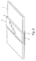
- FIG. 2 shows a simplified perspective view on the security element shown in FIG. 1 .
- the foils 4, 5 and the grooves 2, 3 extend over the entire substrate.
- the lengths of the first and second groove G1L, G2L and the lengths of the first and second foil F1L, F2L are then equal.
- FIG. 3 shows a simplified cross sectional view of a substrate 1 according to an embodiment.
- the reduced thickness of the substrate in the area of the first groove 2 and the second groove 3 is mainly or exclusively achieved by localized drainage variations on the first ply 6 (mould layer).
- the thinner second ply 7 (short-former layer) mainly sinks into the groove on the surface of the first ply 6 which is opposite to the first groove 2.
- the thickness of the first ply 6 is SP1T outside the groove areas of grooves 2, 3.
- the thickness of the second ply 7 is SP2T outside the groove areas of grooves 2, 3.
- the first ply 6 has only thickness of SP1T* with SP1T being greater than SP1T*.
- the second ply 7 has the thickness SP2T* with SP2T* being equal to SP2T.
- the thickness of the remaining layer 8 between the grooves is then SP1T* plus SP2T*.
- the thickness SP1T*+SP2T* of the remaining layer 8 of the substrate in the area in which the first groove and the second groove are superposed can be 80 ⁇ m to 130 ⁇ m. However, this value also depends on the overall thickness of the substrate. In terms of the reduction of the thickness of the substrate due to the first and second groove, the reduction can range from 4 ⁇ m to 35 ⁇ m, and advantageously from 8 ⁇ m to 12 ⁇ m.
- the advantage of using localized varying drainage is that the bottom surface of the grooves remains rather flat over the entire surface of the bottom surface.
- FIG. 4 shows a simplified cross sectional view of a substrate 1 according to another embodiment.
- the first ply 6 only has a groove on its outer surface which is the first groove 2.
- the second groove 3 is formed by removing the second ply 7 in the area of the second groove 3.
- the thickness of the remaining layer 8 of the substrate is then defined by SP1T*, i.e. only by the thickness of the first ply 6 in the area of the first groove 2.
- the second ply 7 is removed first in order to create the second groove 3 and then the first groove 2 is created as result of the missing second ply 7 of the second groove 3.
- the second groove is created first and by natural compensation of the internal tension during the paper formation, the first groove 2 is spontaneously generated on the other side of the substrate.
- FIG. 5 shows a simplified cross sectional view of a substrate 1 according to another embodiment.
- the two grooves 6, 7 are created by calendering.
- the two plies 6, 7 are more compressed inside the area of the grooves 6, 7 than outside the grooves.
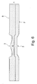
- FIG. 6 shows a simplified cross sectional view of a substrate 1 according to still another embodiment.
- the two groves are formed by mould cover relief modulation. Similar to the embodiment of FIG. 3 , also here two superimposed grooves are only generated on the first ply 6. The thickness of the second ply 7 remains unaffected.
- This well-known method of creating grooves or depressions in fibrous substrates has the disadvantage that the bottom surface of the grooves is uneven and that the edges of the grooves are less steep and sharp than with the other methods of manufacturing the grooves.
- the first foil 4 and/or the second foil 5 can be configured such that the first groove 2 and/or second groove 3 are not perceivable to the naked eye.
- the reduced thickness of the substrate 1 in the area of the grooves 2, 3 can become visible as an increased transparency of the substrate.
- either one or both of the foils 4, 5 can be made substantially opaque.
- the grooves 2, 3 are then hidden due to a specific property of one or both foils 4, 5.
- a pigment may be added to the first and/or second foil 4, 5 in order to make one or both foils 4, 5 opaque.
- a metallic layer may be applied to one or both foils 4, 5 in order to render the grooves unperceivable.
- either one or both of the foils 4, 5 may be made of polymers which are inherently opaque.
- a pigment may be added to the second foil 5 (backside foil) and a metallic or an opaque carrier medium may be added to the first foil 4 (front foil).
Landscapes
- Business, Economics & Management (AREA)
- Accounting & Taxation (AREA)
- Finance (AREA)
- Credit Cards Or The Like (AREA)
Abstract
Description
- The invention relates to a security element and a valuable document comprising a security element. The invention also relates to methods of manufacturing the security element and the valuable document.
- It is well known in the field of valuable documents, as for example banknotes, to incorporate or attach more or less transparent foils to substrates in order to form a security element that prevents counterfeiting of the document. The substrates may be provided with through-windows thereby allowing observation of a security feature located on the foil and arranged in the window.
- Various patents and patent applications, such as
EP 0773220 disclose fibrous substrates in which a foil or other security element is incorporated. The main concern of this kind of prior art consists in compensating the additional thickness contributed by the security element in order to achieve a better flatness. - However, another highly relevant concern which is not sufficiently addressed in the prior art resides in the quality of the security element or valuable document in terms of durability, reproducibility and processability within the various interactions to which the valuable document is subjected to during its life-cycle.
- It is an object of the invention to provide a security element and a valuable document comprising the security element as well as a method of manufacturing the security element and the valuable document which have improved combined properties in terms of costs, durability, reproducibility and processability compared with the prior art.
- According to an aspect of the invention, a security element for a valuable document is provided. The security element comprises a substrate. The substrate, or the plies of the substrate in case of a multi layer substrate, may comprise cellulose fibers, particularly cotton fibers and/or organic synthetic fibers and/or mineral fibers. The substrate can generally be fibrous as for example any paper-like substrate.
- A first groove (or depression) is arranged on a first surface of the substrate, and a second groove (or depression) is arranged on a second surface of the substrate. The second surface of the substrate is opposite to the first surface. The first groove and the second groove face into opposite directions and away from the substrate. The first groove and the second groove are aligned with each other such that the first groove and the second groove are at least substantially superposed. In other words, the two groves substantially coincide or overlap if they are viewed perpendicular to the surface of the substrate.
- Furthermore, the security element comprises at least two elongate flat elements. The elongate elements advantageously have defined and even thickness over their full length and width. They can be attached to the substrate or any ply of the substrate after the grooves in the substrate or in any ply of the substrate has been formed. The elongate elements are advantageously elements in strip form, as for example a foil or a flat element of small size, as for example a patch which is attached to the surface of the ply or substrate. The elongate elements can advantageously be attached once the fibrous substrate or ply has dried, for example outside the papermaking machine production line.
- In an advantageous embodiment of the invention, the elongate elements are a first foil and a second foil. The first foil (front foil) is arranged in the first groove. The second foil (reverse foil) is arranged in the second groove. The thickness of the first foil and the thickness of the second foil would contribute to the overall thickness of the foils and the substrate together. However, the thickness of the first foil and the thickness of the second foil are at least partially or substantially compensated by the dimensions of the first groove and the second groove. Advantageously, the thickness of the first foil and the thickness of the second foil are only partially compensated by the dimensions of the first groove and the second groove. According to this aspect of the invention, a security element is provided that is based on a double groove - double foil concept which provides better quality of the security feature in terms of costs, durability, reproducibility and processability than the prior art and still has sufficient flatness.
- The dimensions of the first groove and the second groove comprise the depth, the length and the width of the first groove and the second groove, respectively. This provides that the additional thickness of the first and second foil is compensated substantially or to a certain extent over the area of the first foil and the second foil. The area of the foils or the grooves is the product of length and width.
- The depth of the first groove can be equal to or lower than the thickness of the first foil. It is particularly noteworthy that the depth of the first groove can be lower than the thickness of the first foil. This is based on the recognition that it is not necessary that the entire thickness of the first foil is compensated by the first groove. In other words, in an embodiment, the thickness of the first foil can therefore be greater than the depth of the first groove, for example by 5 µm to 35 µm.
- The width and length of the first groove, however, are advantageously dimensioned such that the first foil fits into the first groove.
- The thickness of the second foil can also be greater than the depth of the second groove, for example by 5 µm to 20 µm. However, in an advantageous embodiment, the depth of the second groove can be about equal to the thickness of the second foil.
- The present invention, particularly applies to embodiments in which the width of the first groove, the width of the second groove, the width of the first foil and the width of the second foil are equal to or greater than 0.8 cm.
- In one aspect, the width of the first groove can range from 0.8 cm to 3 cm. The width of the second groove can also range from 0.8 cm to 3 cm. The width of the first foil can range from 0.8 to 3 cm. The width of the second foil can range from 1 cm to 4 cm. This implies that the width of the second foil can advantageously always be greater than the width of the second groove.
- The width of the first foil can be equal to or lower than the width of the first groove. The width of the first foil can, for example be slightly lower than the width of the first groove by 1 mm to 6 mm.
- Generally, the thickness of the second foil is at least partially compensated by the second groove. The depth of the second groove can be equal to or lower than the thickness of the second foil. However, it has been found that a slight overlap at the two longitudinal edges of the second foil is acceptable. In other words, the width of the second foil can be equal to or greater than the width of the second groove. The width of the second foil can, for example be greater than the width of the second groove by 1 to 4 mm. The length of the second foil is advantageously equal to the length of the second groove.
- According to an aspect of the invention, the width of the second foil can be greater than the width of the first foil. Dependent on the method of manufacturing the substrate and the grooves, the second groove may inherently be a bit narrower than the first groove. It is then particularly advantageous that a certain overlap over the longitudinal edges of the second groove is acceptable. Although, for example banknotes, undergo a huge number of processing steps from manufacturing until they are sorted out and destroyed, it has been found that the two foils do not need to be entirely embedded in the substrate. A certain additional thickness or thickness variations are tolerable within the limits and definitions given in this specification.
- With respect to a valuable document, the first and second grooves as well as the first and second foils extend over the full length or width of the valuable document. In other words, the two grooves and the two foils of the security element typically all have the same length. This means that the length of the first foil can advantageously be equal to the length of the second foil and also the first groove and the second groove can have the same length.
- In an embodiment, the first and/or second foil advantageously have a width generally ranging between 8 mm and 30 mm, a thickness ranging between 10 µm and 50 µm, and a position from one edge to the opposite edge, across an entire length or an entire width of the substrate and therefore do not occupy the entire surface area of the substrate.
- Furthermore, a layer of the substrate can remain between the first groove and the second groove over the major part of the area in which the first groove and the second groove are superposed. In other words, in the area where the first groove and the second groove are superposed, or coincide, the majority of the substrate is not removed.
- The thickness of the remaining layer of the substrate in the area in which the first groove and the second groove are superposed can be 80 µm 130 µm. However, this value also depends on the overall thickness of the substrate. In terms of the reduction of the thickness of the substrate due to the first groove and the second groove, the reduction can range from 4 µm to 35 µm, and advantageously from 8 µm to 12 µm.
- The security element can further comprise a window in the substrate in the area in which the first groove and the second groove are superposed. In the area of the window, the substrate is entirely removed.
- The security element can further comprise a security feature that is arranged in the first foil and/or the second foil. The security feature can advantageously have a visual effect. The security feature in either the first and/or second foil can then advantageously be arranged in the window. In a preferred embodiment, the security feature is located in the first foil, if the first foil is thicker than the second foil and does not overlap the first groove at the longitudinal edges of the first groove.
- The substrate can be made of a single layer or ply. However, advantageously, the substrate can comprise a plurality of layers of plies. In an embodiment, the substrate may comprise a first ply (layer) of fabric and a second ply of fabric. The first ply and the second ply can extend over the entire substrate. In other words, the substrate can be formed of at least two plies, the first and the second ply.
- The first ply can be thicker than the second ply. The first ply is also referred to as mould layer. The mould layer or first ply can be thicker than the second ply. The second ply is also referred to as short-former layer. The short-former layer is advantageously the thinner layer.
- The invention also provides a method of manufacturing the security element according to the aspects and embodiments of the invention and a method of manufacturing a valuable document, in particular a banknote, comprising the security element.
- There are various different ways of manufacturing the substrate and the first groove and the second groove in the substrate.
- Generally, it can be advantageous, if the grooves are formed by method steps relating to watermarking.
- In one aspect, the first groove can be formed by drainage control, i.e. by a locally reduced dewatering region. By locally different dewatering conditions, a reduced thickness can be achieved in the region of the first groove. This aspect advantageously applies to the first ply, i.e. the mould layer, if the first ply is the thicker layer. The second ply can then sink or settle into a groove on the second surface of the first ply in order to form the second groove. In other words, the drainage control can be used to produce two superposed grooves on the first ply. One of the grooves is the first groove, while the other groove serves as a depression in which the second ply (short-former layer) sinks in order to form the second groove on the opposite surface of the substrate.
- In an advantageous embodiment, the second ply is removed first in order to create the second groove and then the first groove is created as a result of the missing second ply of the second groove. In other words, the second groove is created first, and by natural compensation of the internal tension during the paper formation, the first groove is spontaneously generated on the other side.
- In still another embodiment, the first groove and/or the second groove can be formed by lamination or localized calendering such that the fibers of the substrate are more compressed in the area of the first groove and/or the second groove. In other words, the bottom of the grooves is more compressed, i.e. the remaining layer or layers of the substrate are more compressed.
- Furthermore, the first groove in the first layer can also be formed by mould cover relief.
- Advantageously, the first foil and/or the second foil can be configured such that the first groove and/or second groove are unperceivable to the naked eye. The reduced thickness of the substrate in the area of the grooves can become visible as an increased transparency of the substrate. In order to hide the grooves to the extent that the presence of the grooves is not visible to the naked (unaided) eye, either one or both of the foils can be made substantially opaque. The grooves are then hidden due to a specific property of one or both foils. In an embodiment of the invention, a pigment may be added to the first and/or second foil in order to make one or both foils opaque. In another embodiment, a metallic layer may be applied to one or both foils in order to render the grooves unperceivable. Furthermore, either one or both of the foils may be made of polymers which are inherently opaque. In an advantageous embodiment, a pigment may be added to the second foil (backside foil) and a metallic or an opaque carrier medium may be added to the first foil (front foil).
- The invention also provides a valuable document comprising the security element according to the aspects and embodiments of the invention. The valuable document is advantageously a banknote. The first and second groove as well as the first and second foil may then advantageously extend over the full width or length of the valuable document, in particular the banknote. In other words, the sandwich structure of the first and second groove, remaining layer of the substrate and first and second foil extends over the width or length of the valuable document.
- Further aspects and characteristics of the invention ensue from the following description of the preferred embodiments of the invention with reference to the accompanying drawings, wherein
-
FIG.1 shows a simplified cross-sectional view of a security element; -
FIG. 2 shows a simplified perspective view of the security element shown inFIG. 1 ; -
FIG. 3 shows a cross sectional view of the substrate of an embodiment according to a method of manufacturing; -
FIG. 4 shows a cross sectional view of the substrate of an embodiment according to another method of manufacturing; -
FIG. 5 shows a cross sectional view on the substrate of an embodiment according to a further method of manufacturing; -
FIG. 6 shows a cross sectional view on the substrate of an embodiment according to still another method of manufacturing; -
FIG. 1 shows a simplified cross sectional view of a security element 10 according to an embodiment of the invention. The substrate 1 has afirst grove 2 on a first surface. On the opposite surface of the substrate 1 is asecond groove 3. Thefirst groove 2 and thesecond groove 3 are superimposed, i.e. they are aligned one above the other. Afirst foil 4, in form of an elongate strip, is arranged in thefirst groove 2. Asecond foil 5, also in the form of an elongate strip, is arranged in thesecond groove 3. Thefirst foil 4, thesecond foil 5 and the remaining layer 8 of the substrate 1 between thesuperimposed grooves - The width of the
first foil 4 is F1W. The thickness of thefirst foil 4 is F1T. The width of thesecond foil 5 is F2W. The thickness of thesecond foil 5 is F2T. In this embodiment, the thickness F1T of thefirst foil 4 is greater than the thickness F2T of thesecond foil 5. - The width of the
first groove 2 is G1W. The depth of the first groove is G1T. The width of thesecond groove 3 is G2W. The depth of the second groove is G2T. - The width G1W of the
first groove 2 is slightly greater than the width F1W of thefirst foil 4. This means that the width G1W of thefirst groove 2 is dimensioned such that thefirst foil 2 fits into thefirst groove 2. The thickness F1T of thefirst foil 4 is greater than the depth G1T of thefirst foil 4. This allows even complex security features to be incorporated into thefirst foil 4 rather than into thesecond foil 5 which is thinner than thefirst foil 4. - The thickness F2T of the
second foil 5 is greater than the depth G2T of thesecond groove 3. In fact, the thickness F2T of thesecond foil 5 can even be greater than the sum of the thicknesses G1T, G2T of bothgrooves 2, 3 (i.e. F2T can be greater than G1T + G2T). Generally, the thickness of thesecond foil 5 can be greater than the depth of the second groove, for example by 5 µm to 35 µm. - The width G2W of the
second groove 3 is lower than the width F2W of thesecond foil 5. This means that the width G2W of thesecond groove 3 is dimensioned such that the second foil 5 (slightly) overlaps the longitudinal edges of thesecond groove 3. This small overlap has turned out to be tolerable and it simplifies the manufacturing procedure. The width of thesecond foil 5 can, for example be greater than the width of thesecond groove 3 by 1 mm to 4 mm. - In an advantageous embodiment, the width F2W of the second foil is also greater than the width G1W of the
first groove 2. - The first and/or
second foil - The width G1W of the
first groove 2 can range from 0.8 cm to 3 cm. The width G2W of thesecond groove 3 can also range from 0.8 cm to 3 cm. The width F1W of thefirst foil 4 can range from 0.8 to 3 cm. The width F2W of thesecond foil 5 can range from 1 cm to 4 cm. This implies that the width F2W of thesecond foil 5 can advantageously always be greater than the width G2W of thesecond groove 3. - The width F1W of the
first foil 4 can be equal to or lower than the width G1W of thefirst groove 2. The width F1W of thefirst foil 4 can, for example be lower than the width G1W of thefirst groove 2 by 1 mm to 6 mm. - Generally, the
foils foils grooves - The sandwich structure of the security element 10 provides high quality, stability, durability and processability. According to some aspects of the invention, the
first foil 4 and thesecond foil 5 are not necessarily entirely embedded into the substrate 1. Certain overlaps due to the thickness F1T of thefirst foil 4 and the width F2W of thesecond foil 5 are acceptable. This simplifies production. -
FIG. 2 shows a simplified perspective view on the security element shown inFIG. 1 . Here it can be seen that thefoils grooves foils grooves -
FIG. 3 shows a simplified cross sectional view of a substrate 1 according to an embodiment. In this embodiment, the reduced thickness of the substrate in the area of thefirst groove 2 and thesecond groove 3 is mainly or exclusively achieved by localized drainage variations on the first ply 6 (mould layer). In this case, two grooves are created on thefirst ply 6, while the thinner second ply 7 (short-former layer) mainly sinks into the groove on the surface of thefirst ply 6 which is opposite to thefirst groove 2. The thickness of thefirst ply 6 is SP1T outside the groove areas ofgrooves grooves first groove 2, thefirst ply 6 has only thickness of SP1T* with SP1T being greater than SP1T*. Inside thesecond groove 3, the second ply 7 has the thickness SP2T* with SP2T* being equal to SP2T. The thickness of the remaining layer 8 between the grooves is then SP1T* plus SP2T*. The thickness SP1T*+SP2T* of the remaining layer 8 of the substrate in the area in which the first groove and the second groove are superposed can be 80 µm to 130 µm. However, this value also depends on the overall thickness of the substrate. In terms of the reduction of the thickness of the substrate due to the first and second groove, the reduction can range from 4 µm to 35 µm, and advantageously from 8 µm to 12 µm. - The advantage of using localized varying drainage (locally different dewatering) is that the bottom surface of the grooves remains rather flat over the entire surface of the bottom surface.
-
FIG. 4 shows a simplified cross sectional view of a substrate 1 according to another embodiment. In this embodiment there are also twoplies 6, 7. However, thefirst ply 6 only has a groove on its outer surface which is thefirst groove 2. Thesecond groove 3 is formed by removing the second ply 7 in the area of thesecond groove 3. The thickness of the remaining layer 8 of the substrate is then defined by SP1T*, i.e. only by the thickness of thefirst ply 6 in the area of thefirst groove 2. - In an advantageous embodiment, the second ply 7 is removed first in order to create the
second groove 3 and then thefirst groove 2 is created as result of the missing second ply 7 of thesecond groove 3. In other words, the second groove is created first and by natural compensation of the internal tension during the paper formation, thefirst groove 2 is spontaneously generated on the other side of the substrate. -
FIG. 5 shows a simplified cross sectional view of a substrate 1 according to another embodiment. In this embodiment, the twogrooves 6, 7 are created by calendering. The twoplies 6, 7 are more compressed inside the area of thegrooves 6, 7 than outside the grooves. -
FIG. 6 shows a simplified cross sectional view of a substrate 1 according to still another embodiment. In this embodiment, the two groves are formed by mould cover relief modulation. Similar to the embodiment ofFIG. 3 , also here two superimposed grooves are only generated on thefirst ply 6. The thickness of the second ply 7 remains unaffected. This well-known method of creating grooves or depressions in fibrous substrates has the disadvantage that the bottom surface of the grooves is uneven and that the edges of the grooves are less steep and sharp than with the other methods of manufacturing the grooves. - In the previously described embodiments of the invention, the
first foil 4 and/or thesecond foil 5 can be configured such that thefirst groove 2 and/orsecond groove 3 are not perceivable to the naked eye. The reduced thickness of the substrate 1 in the area of thegrooves grooves foils grooves foils second foil foils foils foils - Although the invention has been described hereinabove with reference to specific embodiments, it is not limited to these embodiments and no doubt further alternatives will occur to the skilled person that lie within the scope of the invention as claimed.
-
- Substrate 1
-
First groove 2 -
Second groove 3 -
First foil 4 -
Second foil 5 - First ply of
substrate 6 - Second ply of substrate 7
- Remaining layer of substrate 8
- First groove thickness G1T
- First groove width G1W
- First groove length G1 L
- Second groove thickness G2T
- Second groove width G2W
- Second groove length G2L
- First foil thickness F1T
- First foil width F1W
- First foil length F1L
- Second foil thickness F2T
- Second foil width F2W
- Second foil length F2L
- Thickness of remaining layer of substrate SRLT
- Thickness of first ply of substrate SP1T
- Thickness of second ply of substrate SP2T
- Thickness of first ply within first groove SP1T*
- Thickness of second ply within second groove SP2T*
Claims (15)
- A security element for a valuable document comprising a substrate, a first groove on a first surface of the substrate, a second groove on a second surface of the substrate, the second surface being opposite to the first surface wherein the first groove and the second groove are aligned with each other such that first groove and the second groove are substantially superposed and a first foil is arranged in the first groove and a second foil is arranged in the second groove such that the thickness of the first foil and the thickness of the second foil are partially compensated by the dimensions of the first groove and the second groove.
- The security element of claim 1, wherein the depth of the first groove is equal to or lower than the thickness of the first foil and/or the width of the first foil is equal to or lower than the width of the first groove and/or the width of the second foil is equal to or greater than the width of the second groove and/or the thickness of the second foil is lower than the thickness of the first foil and/or the width of the second foil is greater than the width of the first foil.
- The security element according to anyone of the preceding claims, wherein the length of the first foil is equal to the length of the first groove and/or the length of the second foil is equal to the length of the second groove and/or the length of the first foil is equal to the length of the second foil.
- The security element according to anyone of the preceding claims, wherein a layer of the substrate remains between the first groove and the second groove over the major part of the area in which the first groove and the second groove are superposed.
- The security element according to anyone of the preceding claims, further comprising a window in the substrate in the area in which the first groove and the second groove are superposed such that the substrate is entirely removed within the window.
- The security element according to claim 5, further comprising a security feature in the first foil having a visual effect and wherein the security feature is arranged in the window of the substrate.
- The security element according to anyone of the preceding claims, wherein the substrate comprises a first ply and a second ply and wherein the first ply and the second ply extend over the entire substrate.
- The security element according to claim 7, wherein the first ply is thicker than the second ply.
- The security element according to claim 7 or 8, wherein the first groove is formed by drainage control and wherein the second groove is formed by a groove in the first ply such that the second ply is arranged in the groove on the second surface of the first ply in order to form the second groove.
- The security element according to claim 7 or 8, wherein the second ply is locally removed in order to form the second groove and the first groove.
- The security element according to claim 7 or 8, wherein the first groove is formed by lamination or localized calendering such that the fibers of the substrate are more compressed in the area of the first groove.
- The security element according to claim 7 or 8, wherein the first groove in the first layer is formed by mould cover relief.
- The security element according to anyone of the previous claims, wherein the first foil and/or the second foil are configured such that the first groove and/or second groove are not perceivable by the naked eye.
- A valuable document comprising a security element according to anyone of the preceding claims.
- A method of manufacturing a security element in accordance with anyone of claims 1 to 13 or a method of manufacturing a valuable document in accordance with claim 14.
Priority Applications (2)
| Application Number | Priority Date | Filing Date | Title |
|---|---|---|---|
| ES13188267.2T ES2611960T3 (en) | 2013-10-11 | 2013-10-11 | Security element, value document comprising a security element and method for manufacturing the security element and the value document |
| EP13188267.2A EP2860040B1 (en) | 2013-10-11 | 2013-10-11 | A security element, a valuable document comprising a security element and method for manufacturing the security element and the valuable document |
Applications Claiming Priority (1)
| Application Number | Priority Date | Filing Date | Title |
|---|---|---|---|
| EP13188267.2A EP2860040B1 (en) | 2013-10-11 | 2013-10-11 | A security element, a valuable document comprising a security element and method for manufacturing the security element and the valuable document |
Publications (2)
| Publication Number | Publication Date |
|---|---|
| EP2860040A1 true EP2860040A1 (en) | 2015-04-15 |
| EP2860040B1 EP2860040B1 (en) | 2016-12-07 |
Family
ID=49356249
Family Applications (1)
| Application Number | Title | Priority Date | Filing Date |
|---|---|---|---|
| EP13188267.2A Active EP2860040B1 (en) | 2013-10-11 | 2013-10-11 | A security element, a valuable document comprising a security element and method for manufacturing the security element and the valuable document |
Country Status (2)
| Country | Link |
|---|---|
| EP (1) | EP2860040B1 (en) |
| ES (1) | ES2611960T3 (en) |
Cited By (4)
| Publication number | Priority date | Publication date | Assignee | Title |
|---|---|---|---|---|
| WO2017137369A1 (en) | 2016-02-10 | 2017-08-17 | Oberthur Fiduciaire Sas | Method for producing security documents and corresponding documents |
| WO2018115515A1 (en) | 2016-12-23 | 2018-06-28 | Oberthur Fiduciaire Sas | Secure document |
| EP3623528A1 (en) | 2018-09-14 | 2020-03-18 | Oberthur Fiduciaire SAS | Method for manufacturing a sheet material, corresponding machine, sheet material and safety document |
| DE102021003553A1 (en) | 2021-06-28 | 2022-12-29 | Giesecke+Devrient Currency Technology Gmbh | security substrate |
Families Citing this family (1)
| Publication number | Priority date | Publication date | Assignee | Title |
|---|---|---|---|---|
| DE102019006890A1 (en) | 2019-10-02 | 2021-04-08 | Giesecke+Devrient Currency Technology Gmbh | Manufacturing process for a security paper and security paper obtainable therewith |
Citations (5)
| Publication number | Priority date | Publication date | Assignee | Title |
|---|---|---|---|---|
| US5248544A (en) * | 1990-02-01 | 1993-09-28 | Gao Gesellschaft Fur Automation Und Organisation Mbh | Paper of value having an optically variable security element |
| EP0773220A1 (en) | 1995-11-09 | 1997-05-14 | SUMIKA FINE CHEMICALS Co., Ltd. | 2-Amino-6-chloropurine and method for preparing the same |
| WO1999037488A1 (en) * | 1998-01-21 | 1999-07-29 | Securency Pty. Ltd. | Method of verifying the authenticity of a security document and document for use in such a method |
| WO2003053713A1 (en) * | 2001-12-21 | 2003-07-03 | Giesecke & Devrient Gmbh | Security element for security papers and valuable documents |
| EP2199095A2 (en) * | 2008-12-17 | 2010-06-23 | Giesecke & Devrient GmbH | Safety element for data carrier and method for producing same |
-
2013
- 2013-10-11 EP EP13188267.2A patent/EP2860040B1/en active Active
- 2013-10-11 ES ES13188267.2T patent/ES2611960T3/en active Active
Patent Citations (5)
| Publication number | Priority date | Publication date | Assignee | Title |
|---|---|---|---|---|
| US5248544A (en) * | 1990-02-01 | 1993-09-28 | Gao Gesellschaft Fur Automation Und Organisation Mbh | Paper of value having an optically variable security element |
| EP0773220A1 (en) | 1995-11-09 | 1997-05-14 | SUMIKA FINE CHEMICALS Co., Ltd. | 2-Amino-6-chloropurine and method for preparing the same |
| WO1999037488A1 (en) * | 1998-01-21 | 1999-07-29 | Securency Pty. Ltd. | Method of verifying the authenticity of a security document and document for use in such a method |
| WO2003053713A1 (en) * | 2001-12-21 | 2003-07-03 | Giesecke & Devrient Gmbh | Security element for security papers and valuable documents |
| EP2199095A2 (en) * | 2008-12-17 | 2010-06-23 | Giesecke & Devrient GmbH | Safety element for data carrier and method for producing same |
Cited By (4)
| Publication number | Priority date | Publication date | Assignee | Title |
|---|---|---|---|---|
| WO2017137369A1 (en) | 2016-02-10 | 2017-08-17 | Oberthur Fiduciaire Sas | Method for producing security documents and corresponding documents |
| WO2018115515A1 (en) | 2016-12-23 | 2018-06-28 | Oberthur Fiduciaire Sas | Secure document |
| EP3623528A1 (en) | 2018-09-14 | 2020-03-18 | Oberthur Fiduciaire SAS | Method for manufacturing a sheet material, corresponding machine, sheet material and safety document |
| DE102021003553A1 (en) | 2021-06-28 | 2022-12-29 | Giesecke+Devrient Currency Technology Gmbh | security substrate |
Also Published As
| Publication number | Publication date |
|---|---|
| ES2611960T3 (en) | 2017-05-11 |
| EP2860040B1 (en) | 2016-12-07 |
Similar Documents
| Publication | Publication Date | Title |
|---|---|---|
| EP2860040A1 (en) | A Security Element, a Valuable Document comprising a Security Element and Methods for Manufacturing the Security Element and the Valuable Document | |
| RU2315832C2 (en) | Counterfeit-proof paper, method and apparatus for manufacturing the same | |
| RU2652225C9 (en) | Substrate for security papers and method of manufacturing same | |
| US8268128B2 (en) | Security substrates | |
| EP1929090B2 (en) | Security device for security substrates | |
| CN101978112B (en) | Method of making sheets for security documents | |
| RU2683653C2 (en) | Security paper (options) and methods for manufacture thereof (options) | |
| US20100181036A1 (en) | Process for manufacturing a sheet material | |
| GB2543053A (en) | A security document | |
| US20100207377A1 (en) | Process for manufacturing a sheet material | |
| CN107250459B (en) | Method for surface application of a security device to a substrate | |
| US20140238628A1 (en) | Method for Manufacturing a Security Paper and Microlens Thread | |
| CA2646275C (en) | Identity document with tissue reinforcement | |
| GB2395724A (en) | Fibrous substrate incorporating electronic chips | |
| EP2886364B1 (en) | Security document and method for the production of a security document | |
| EP2860310A1 (en) | Improvements in paper manufacturing | |
| EP2993057B1 (en) | Banknote with window | |
| CN104372716A (en) | Reproduction anti-counterfeiting safety line, reproduction anti-counterfeiting method adopting reproduction anti-counterfeiting safety line, and anti-counterfeiting paper product prepared through reproduction anti-counterfeiting method | |
| WO2012015331A1 (en) | Multilayered paper with reinforcing strips for the production of valuable documents |
Legal Events
| Date | Code | Title | Description |
|---|---|---|---|
| PUAI | Public reference made under article 153(3) epc to a published international application that has entered the european phase |
Free format text: ORIGINAL CODE: 0009012 |
|
| 17P | Request for examination filed |
Effective date: 20131011 |
|
| AK | Designated contracting states |
Kind code of ref document: A1 Designated state(s): AL AT BE BG CH CY CZ DE DK EE ES FI FR GB GR HR HU IE IS IT LI LT LU LV MC MK MT NL NO PL PT RO RS SE SI SK SM TR |
|
| AX | Request for extension of the european patent |
Extension state: BA ME |
|
| R17P | Request for examination filed (corrected) |
Effective date: 20151015 |
|
| RBV | Designated contracting states (corrected) |
Designated state(s): AL AT BE BG CH CY CZ DE DK EE ES FI FR GB GR HR HU IE IS IT LI LT LU LV MC MK MT NL NO PL PT RO RS SE SI SK SM TR |
|
| REG | Reference to a national code |
Ref country code: DE Ref legal event code: R079 Ref document number: 602013014965 Country of ref document: DE Free format text: PREVIOUS MAIN CLASS: B42D0015000000 Ipc: B42D0025290000 |
|
| GRAP | Despatch of communication of intention to grant a patent |
Free format text: ORIGINAL CODE: EPIDOSNIGR1 |
|
| RIC1 | Information provided on ipc code assigned before grant |
Ipc: B42D 25/29 20140101AFI20160503BHEP |
|
| INTG | Intention to grant announced |
Effective date: 20160520 |
|
| GRAS | Grant fee paid |
Free format text: ORIGINAL CODE: EPIDOSNIGR3 |
|
| GRAA | (expected) grant |
Free format text: ORIGINAL CODE: 0009210 |
|
| AK | Designated contracting states |
Kind code of ref document: B1 Designated state(s): AL AT BE BG CH CY CZ DE DK EE ES FI FR GB GR HR HU IE IS IT LI LT LU LV MC MK MT NL NO PL PT RO RS SE SI SK SM TR |
|
| REG | Reference to a national code |
Ref country code: GB Ref legal event code: FG4D |
|
| REG | Reference to a national code |
Ref country code: CH Ref legal event code: EP Ref country code: CH Ref legal event code: NV Representative=s name: BUGNION S.A., CH Ref country code: AT Ref legal event code: REF Ref document number: 851358 Country of ref document: AT Kind code of ref document: T Effective date: 20161215 |
|
| REG | Reference to a national code |
Ref country code: IE Ref legal event code: FG4D |
|
| REG | Reference to a national code |
Ref country code: DE Ref legal event code: R096 Ref document number: 602013014965 Country of ref document: DE |
|
| REG | Reference to a national code |
Ref country code: NL Ref legal event code: FP |
|
| PG25 | Lapsed in a contracting state [announced via postgrant information from national office to epo] |
Ref country code: LV Free format text: LAPSE BECAUSE OF FAILURE TO SUBMIT A TRANSLATION OF THE DESCRIPTION OR TO PAY THE FEE WITHIN THE PRESCRIBED TIME-LIMIT Effective date: 20161207 |
|
| REG | Reference to a national code |
Ref country code: LT Ref legal event code: MG4D |
|
| PG25 | Lapsed in a contracting state [announced via postgrant information from national office to epo] |
Ref country code: SE Free format text: LAPSE BECAUSE OF FAILURE TO SUBMIT A TRANSLATION OF THE DESCRIPTION OR TO PAY THE FEE WITHIN THE PRESCRIBED TIME-LIMIT Effective date: 20161207 Ref country code: GR Free format text: LAPSE BECAUSE OF FAILURE TO SUBMIT A TRANSLATION OF THE DESCRIPTION OR TO PAY THE FEE WITHIN THE PRESCRIBED TIME-LIMIT Effective date: 20170308 Ref country code: LT Free format text: LAPSE BECAUSE OF FAILURE TO SUBMIT A TRANSLATION OF THE DESCRIPTION OR TO PAY THE FEE WITHIN THE PRESCRIBED TIME-LIMIT Effective date: 20161207 Ref country code: NO Free format text: LAPSE BECAUSE OF FAILURE TO SUBMIT A TRANSLATION OF THE DESCRIPTION OR TO PAY THE FEE WITHIN THE PRESCRIBED TIME-LIMIT Effective date: 20170307 |
|
| REG | Reference to a national code |
Ref country code: ES Ref legal event code: FG2A Ref document number: 2611960 Country of ref document: ES Kind code of ref document: T3 Effective date: 20170511 |
|
| PG25 | Lapsed in a contracting state [announced via postgrant information from national office to epo] |
Ref country code: RS Free format text: LAPSE BECAUSE OF FAILURE TO SUBMIT A TRANSLATION OF THE DESCRIPTION OR TO PAY THE FEE WITHIN THE PRESCRIBED TIME-LIMIT Effective date: 20161207 Ref country code: FI Free format text: LAPSE BECAUSE OF FAILURE TO SUBMIT A TRANSLATION OF THE DESCRIPTION OR TO PAY THE FEE WITHIN THE PRESCRIBED TIME-LIMIT Effective date: 20161207 Ref country code: HR Free format text: LAPSE BECAUSE OF FAILURE TO SUBMIT A TRANSLATION OF THE DESCRIPTION OR TO PAY THE FEE WITHIN THE PRESCRIBED TIME-LIMIT Effective date: 20161207 |
|
| PG25 | Lapsed in a contracting state [announced via postgrant information from national office to epo] |
Ref country code: IS Free format text: LAPSE BECAUSE OF FAILURE TO SUBMIT A TRANSLATION OF THE DESCRIPTION OR TO PAY THE FEE WITHIN THE PRESCRIBED TIME-LIMIT Effective date: 20170407 Ref country code: RO Free format text: LAPSE BECAUSE OF FAILURE TO SUBMIT A TRANSLATION OF THE DESCRIPTION OR TO PAY THE FEE WITHIN THE PRESCRIBED TIME-LIMIT Effective date: 20161207 Ref country code: EE Free format text: LAPSE BECAUSE OF FAILURE TO SUBMIT A TRANSLATION OF THE DESCRIPTION OR TO PAY THE FEE WITHIN THE PRESCRIBED TIME-LIMIT Effective date: 20161207 Ref country code: CZ Free format text: LAPSE BECAUSE OF FAILURE TO SUBMIT A TRANSLATION OF THE DESCRIPTION OR TO PAY THE FEE WITHIN THE PRESCRIBED TIME-LIMIT Effective date: 20161207 Ref country code: SK Free format text: LAPSE BECAUSE OF FAILURE TO SUBMIT A TRANSLATION OF THE DESCRIPTION OR TO PAY THE FEE WITHIN THE PRESCRIBED TIME-LIMIT Effective date: 20161207 |
|
| PG25 | Lapsed in a contracting state [announced via postgrant information from national office to epo] |
Ref country code: SM Free format text: LAPSE BECAUSE OF FAILURE TO SUBMIT A TRANSLATION OF THE DESCRIPTION OR TO PAY THE FEE WITHIN THE PRESCRIBED TIME-LIMIT Effective date: 20161207 Ref country code: PL Free format text: LAPSE BECAUSE OF FAILURE TO SUBMIT A TRANSLATION OF THE DESCRIPTION OR TO PAY THE FEE WITHIN THE PRESCRIBED TIME-LIMIT Effective date: 20161207 Ref country code: BE Free format text: LAPSE BECAUSE OF FAILURE TO SUBMIT A TRANSLATION OF THE DESCRIPTION OR TO PAY THE FEE WITHIN THE PRESCRIBED TIME-LIMIT Effective date: 20161207 Ref country code: PT Free format text: LAPSE BECAUSE OF FAILURE TO SUBMIT A TRANSLATION OF THE DESCRIPTION OR TO PAY THE FEE WITHIN THE PRESCRIBED TIME-LIMIT Effective date: 20170407 Ref country code: BG Free format text: LAPSE BECAUSE OF FAILURE TO SUBMIT A TRANSLATION OF THE DESCRIPTION OR TO PAY THE FEE WITHIN THE PRESCRIBED TIME-LIMIT Effective date: 20170307 |
|
| REG | Reference to a national code |
Ref country code: DE Ref legal event code: R097 Ref document number: 602013014965 Country of ref document: DE |
|
| PLBE | No opposition filed within time limit |
Free format text: ORIGINAL CODE: 0009261 |
|
| STAA | Information on the status of an ep patent application or granted ep patent |
Free format text: STATUS: NO OPPOSITION FILED WITHIN TIME LIMIT |
|
| REG | Reference to a national code |
Ref country code: FR Ref legal event code: PLFP Year of fee payment: 5 |
|
| 26N | No opposition filed |
Effective date: 20170908 |
|
| PG25 | Lapsed in a contracting state [announced via postgrant information from national office to epo] |
Ref country code: DK Free format text: LAPSE BECAUSE OF FAILURE TO SUBMIT A TRANSLATION OF THE DESCRIPTION OR TO PAY THE FEE WITHIN THE PRESCRIBED TIME-LIMIT Effective date: 20161207 Ref country code: SI Free format text: LAPSE BECAUSE OF FAILURE TO SUBMIT A TRANSLATION OF THE DESCRIPTION OR TO PAY THE FEE WITHIN THE PRESCRIBED TIME-LIMIT Effective date: 20161207 |
|
| PG25 | Lapsed in a contracting state [announced via postgrant information from national office to epo] |
Ref country code: MC Free format text: LAPSE BECAUSE OF FAILURE TO SUBMIT A TRANSLATION OF THE DESCRIPTION OR TO PAY THE FEE WITHIN THE PRESCRIBED TIME-LIMIT Effective date: 20161207 |
|
| REG | Reference to a national code |
Ref country code: IE Ref legal event code: MM4A |
|
| PG25 | Lapsed in a contracting state [announced via postgrant information from national office to epo] |
Ref country code: LU Free format text: LAPSE BECAUSE OF NON-PAYMENT OF DUE FEES Effective date: 20171011 |
|
| PG25 | Lapsed in a contracting state [announced via postgrant information from national office to epo] |
Ref country code: MT Free format text: LAPSE BECAUSE OF NON-PAYMENT OF DUE FEES Effective date: 20171011 |
|
| REG | Reference to a national code |
Ref country code: FR Ref legal event code: PLFP Year of fee payment: 6 |
|
| PG25 | Lapsed in a contracting state [announced via postgrant information from national office to epo] |
Ref country code: IE Free format text: LAPSE BECAUSE OF NON-PAYMENT OF DUE FEES Effective date: 20171011 |
|
| PG25 | Lapsed in a contracting state [announced via postgrant information from national office to epo] |
Ref country code: HU Free format text: LAPSE BECAUSE OF FAILURE TO SUBMIT A TRANSLATION OF THE DESCRIPTION OR TO PAY THE FEE WITHIN THE PRESCRIBED TIME-LIMIT; INVALID AB INITIO Effective date: 20131011 |
|
| PG25 | Lapsed in a contracting state [announced via postgrant information from national office to epo] |
Ref country code: CY Free format text: LAPSE BECAUSE OF FAILURE TO SUBMIT A TRANSLATION OF THE DESCRIPTION OR TO PAY THE FEE WITHIN THE PRESCRIBED TIME-LIMIT Effective date: 20161207 |
|
| REG | Reference to a national code |
Ref country code: AT Ref legal event code: UEP Ref document number: 851358 Country of ref document: AT Kind code of ref document: T Effective date: 20161207 |
|
| PG25 | Lapsed in a contracting state [announced via postgrant information from national office to epo] |
Ref country code: MK Free format text: LAPSE BECAUSE OF FAILURE TO SUBMIT A TRANSLATION OF THE DESCRIPTION OR TO PAY THE FEE WITHIN THE PRESCRIBED TIME-LIMIT Effective date: 20161207 |
|
| PG25 | Lapsed in a contracting state [announced via postgrant information from national office to epo] |
Ref country code: TR Free format text: LAPSE BECAUSE OF FAILURE TO SUBMIT A TRANSLATION OF THE DESCRIPTION OR TO PAY THE FEE WITHIN THE PRESCRIBED TIME-LIMIT Effective date: 20161207 |
|
| PG25 | Lapsed in a contracting state [announced via postgrant information from national office to epo] |
Ref country code: AL Free format text: LAPSE BECAUSE OF FAILURE TO SUBMIT A TRANSLATION OF THE DESCRIPTION OR TO PAY THE FEE WITHIN THE PRESCRIBED TIME-LIMIT Effective date: 20161207 |
|
| P01 | Opt-out of the competence of the unified patent court (upc) registered |
Effective date: 20230515 |
|
| PGFP | Annual fee paid to national office [announced via postgrant information from national office to epo] |
Ref country code: NL Payment date: 20231019 Year of fee payment: 11 |
|
| PGFP | Annual fee paid to national office [announced via postgrant information from national office to epo] |
Ref country code: GB Payment date: 20231020 Year of fee payment: 11 |
|
| PGFP | Annual fee paid to national office [announced via postgrant information from national office to epo] |
Ref country code: ES Payment date: 20231227 Year of fee payment: 11 |
|
| PGFP | Annual fee paid to national office [announced via postgrant information from national office to epo] |
Ref country code: IT Payment date: 20231026 Year of fee payment: 11 Ref country code: FR Payment date: 20231025 Year of fee payment: 11 Ref country code: DE Payment date: 20231026 Year of fee payment: 11 Ref country code: CH Payment date: 20231102 Year of fee payment: 11 Ref country code: AT Payment date: 20231020 Year of fee payment: 11 |