EP2859846A1 - Sensor and shape retainer - Google Patents
Sensor and shape retainer Download PDFInfo
- Publication number
- EP2859846A1 EP2859846A1 EP20140187000 EP14187000A EP2859846A1 EP 2859846 A1 EP2859846 A1 EP 2859846A1 EP 20140187000 EP20140187000 EP 20140187000 EP 14187000 A EP14187000 A EP 14187000A EP 2859846 A1 EP2859846 A1 EP 2859846A1
- Authority
- EP
- European Patent Office
- Prior art keywords
- cable
- sensor
- flexibility
- shape
- bent
- Prior art date
- Legal status (The legal status is an assumption and is not a legal conclusion. Google has not performed a legal analysis and makes no representation as to the accuracy of the status listed.)
- Granted
Links
- 0 C*1(*)C=C=CC1 Chemical compound C*1(*)C=C=CC1 0.000 description 1
Images





Classifications
-
- A—HUMAN NECESSITIES
- A61—MEDICAL OR VETERINARY SCIENCE; HYGIENE
- A61B—DIAGNOSIS; SURGERY; IDENTIFICATION
- A61B5/00—Measuring for diagnostic purposes; Identification of persons
- A61B5/68—Arrangements of detecting, measuring or recording means, e.g. sensors, in relation to patient
- A61B5/6801—Arrangements of detecting, measuring or recording means, e.g. sensors, in relation to patient specially adapted to be attached to or worn on the body surface
- A61B5/683—Means for maintaining contact with the body
- A61B5/6838—Clamps or clips
-
- A—HUMAN NECESSITIES
- A61—MEDICAL OR VETERINARY SCIENCE; HYGIENE
- A61B—DIAGNOSIS; SURGERY; IDENTIFICATION
- A61B5/00—Measuring for diagnostic purposes; Identification of persons
- A61B5/02—Detecting, measuring or recording for evaluating the cardiovascular system, e.g. pulse, heart rate, blood pressure or blood flow
- A61B5/0205—Simultaneously evaluating both cardiovascular conditions and different types of body conditions, e.g. heart and respiratory condition
-
- A—HUMAN NECESSITIES
- A61—MEDICAL OR VETERINARY SCIENCE; HYGIENE
- A61B—DIAGNOSIS; SURGERY; IDENTIFICATION
- A61B5/00—Measuring for diagnostic purposes; Identification of persons
- A61B5/145—Measuring characteristics of blood in vivo, e.g. gas concentration or pH-value ; Measuring characteristics of body fluids or tissues, e.g. interstitial fluid or cerebral tissue
- A61B5/1455—Measuring characteristics of blood in vivo, e.g. gas concentration or pH-value ; Measuring characteristics of body fluids or tissues, e.g. interstitial fluid or cerebral tissue using optical sensors, e.g. spectral photometrical oximeters
-
- A—HUMAN NECESSITIES
- A61—MEDICAL OR VETERINARY SCIENCE; HYGIENE
- A61B—DIAGNOSIS; SURGERY; IDENTIFICATION
- A61B5/00—Measuring for diagnostic purposes; Identification of persons
- A61B5/145—Measuring characteristics of blood in vivo, e.g. gas concentration or pH-value ; Measuring characteristics of body fluids or tissues, e.g. interstitial fluid or cerebral tissue
- A61B5/1455—Measuring characteristics of blood in vivo, e.g. gas concentration or pH-value ; Measuring characteristics of body fluids or tissues, e.g. interstitial fluid or cerebral tissue using optical sensors, e.g. spectral photometrical oximeters
- A61B5/14551—Measuring characteristics of blood in vivo, e.g. gas concentration or pH-value ; Measuring characteristics of body fluids or tissues, e.g. interstitial fluid or cerebral tissue using optical sensors, e.g. spectral photometrical oximeters for measuring blood gases
-
- A—HUMAN NECESSITIES
- A61—MEDICAL OR VETERINARY SCIENCE; HYGIENE
- A61B—DIAGNOSIS; SURGERY; IDENTIFICATION
- A61B5/00—Measuring for diagnostic purposes; Identification of persons
- A61B5/68—Arrangements of detecting, measuring or recording means, e.g. sensors, in relation to patient
- A61B5/6801—Arrangements of detecting, measuring or recording means, e.g. sensors, in relation to patient specially adapted to be attached to or worn on the body surface
- A61B5/6813—Specially adapted to be attached to a specific body part
- A61B5/6814—Head
- A61B5/6815—Ear
- A61B5/6816—Ear lobe
-
- A—HUMAN NECESSITIES
- A61—MEDICAL OR VETERINARY SCIENCE; HYGIENE
- A61B—DIAGNOSIS; SURGERY; IDENTIFICATION
- A61B5/00—Measuring for diagnostic purposes; Identification of persons
- A61B5/68—Arrangements of detecting, measuring or recording means, e.g. sensors, in relation to patient
- A61B5/6801—Arrangements of detecting, measuring or recording means, e.g. sensors, in relation to patient specially adapted to be attached to or worn on the body surface
- A61B5/6813—Specially adapted to be attached to a specific body part
- A61B5/6825—Hand
- A61B5/6826—Finger
-
- A—HUMAN NECESSITIES
- A61—MEDICAL OR VETERINARY SCIENCE; HYGIENE
- A61B—DIAGNOSIS; SURGERY; IDENTIFICATION
- A61B2562/00—Details of sensors; Constructional details of sensor housings or probes; Accessories for sensors
- A61B2562/22—Arrangements of medical sensors with cables or leads; Connectors or couplings specifically adapted for medical sensors
- A61B2562/221—Arrangements of sensors with cables or leads, e.g. cable harnesses
-
- A—HUMAN NECESSITIES
- A61—MEDICAL OR VETERINARY SCIENCE; HYGIENE
- A61B—DIAGNOSIS; SURGERY; IDENTIFICATION
- A61B5/00—Measuring for diagnostic purposes; Identification of persons
- A61B5/02—Detecting, measuring or recording for evaluating the cardiovascular system, e.g. pulse, heart rate, blood pressure or blood flow
- A61B5/024—Measuring pulse rate or heart rate
- A61B5/02416—Measuring pulse rate or heart rate using photoplethysmograph signals, e.g. generated by infrared radiation
-
- A—HUMAN NECESSITIES
- A61—MEDICAL OR VETERINARY SCIENCE; HYGIENE
- A61B—DIAGNOSIS; SURGERY; IDENTIFICATION
- A61B5/00—Measuring for diagnostic purposes; Identification of persons
- A61B5/02—Detecting, measuring or recording for evaluating the cardiovascular system, e.g. pulse, heart rate, blood pressure or blood flow
- A61B5/024—Measuring pulse rate or heart rate
- A61B5/02438—Measuring pulse rate or heart rate with portable devices, e.g. worn by the patient
Definitions
- the invention relates to a sensor which is attached to a living body to detect biological information, and also to a shape retainer which is attached to a cable for transmitting a signal corresponding to the biological information.
- a procedure of securing the cable to the skin of the subject with an adhesive tape is sometimes performed.
- a sensor is sometimes used in which a securing device having a predetermined shape is attached to the cable (for example, see JP-UM-A-7-028502 ). The securing device is secured to a part of the body of the subject to prevent the cable from swinging.
- JP-UM-A-7-028502 has the predetermined shape corresponding to the attaching place of the body. Therefore, the degree of freedom of selection of the place where the cable is to be secured is low.
- an object of the invention is to provide a technique for enhancing the degree of freedom of selection of the place where a cable of a sensor for detecting biological information is to be secured.
- a first aspect of the invention is a sensor which is attached to a living body, wherein the sensor includes:
- the second portion can be freely bent based on the second flexibility, and therefore can be deformed so as to extend along a desired portion of the body of the subject. Moreover, the second portion can be deformed so as to extend along the body shape which varies from subject to subject. As a result, the cable can be secured to a desired portion of the body of the subject. Furthermore, the second portion can self-retain the bent shape based on the second flexibility, and therefore an adhesive tape or an additional securing device is not required in the securement. Consequently, it is possible to enhance the degree of freedom of selection of the place where the cable of the sensor for detecting biological information is to be secured.
- the second portion may include large-diameter parts having a first maximum diameter, and small-diameter parts having a second maximum diameter which is smaller than the first maximum diameter.
- a body portion of the subject to which the second portion is attached has irregular convex and concave portions.
- difference in size formed between the large-diameter parts and the small-diameter parts can be easily caught by the irregular convex and concave portions, so that the cable can be secured more surely to a body portion of the subject. Therefore, it is possible to enhance the degree of freedom of selection of the place where the cable of the sensor for detecting biological information is to be secured.
- the large-diameter parts may be formed by a material having a third flexibility which is higher than the first flexibility.
- the burden on the skin of the subject can be suppressed. Therefore, it is possible to enhance the degree of freedom of selection of the place where the cable of the sensor for detecting biological information is to be secured.
- the second portion may be attachable to and detachable from the first portion.
- the second portion also may have a core line embedded in the whole length of the second portion in a longitudinal direction of the second portion.
- a portion of the cable in which a bent state must be retained can be arbitrarily set. Therefore, it is possible to enhance the degree of freedom of selection of the place where the cable of the sensor for detecting biological information is to be secured.
- the second portion functions as a shape retainer that is attached to the cable of the sensor which is attached to a living body to detect biological information, and that retains the shape of the cable to a desired state.
- a second aspect of the invention is a shape retainer attached to a cable for transmitting a signal, wherein the shape retainer has a second flexibility which is lower than a first flexibility of the cable, and the second flexibility allows the retainer to be bent and to retain a shape which is in a bent state.
- the shape retainer can be attached to an adequate cable for transmitting a signal. In a state where a cable of an electronic apparatus is bent, and secured to a desired place, for example, the shape retainer can retain the bent shape.
- Fig. 1 is a perspective view illustrating a sensor 1 of a first embodiment of the invention.
- the sensor 1 attached to a living body (subject) can include a sensor body 10 and a cable 20.
- the sensor 1 is used as a probe of a pulse oximeter.
- the sensor body 10 has a clip-like shape, and is configured so as to be able to clamp a portion (fingertip, earlobe, or the like) of the body of the subject.
- the sensor body 10 can include a light emitter 11 and a light detector 12.
- the light emitter 11 is configured so as to emit a red light and an infrared light.
- the light detector 12 is configured so as to output signals corresponding to the intensities of the light which have been passed through the body part of the subject clamped by the sensor body 10.
- the sensor body 10 outputs signals corresponding respectively to the SpO2 and heart rate which are examples of biological information.
- the cable 20 transmits the signals output from the light detector 12 to the pulse oximeter which is not shown.
- the pulse oximeter measures the SpO2 and heart rate which are described above, based on the transmitted signals.
- the cable 20 can include a first portion 21 and a second portion 22. One end of the first portion 21 is connected to the light detector 12, and the other end of the first portion 21 is connected to the pulse oximeter.
- the first portion 21 has a first flexibility.
- the first flexibility is at a degree which enables the first portion to be bent, and which disables the first portion to retain the shape in a bent state.
- the second portion 22 is disposed so as to partly cover the first portion 21.
- the second portion 22 has a second flexibility.
- the second flexibility is lower than the first flexibility.
- the second flexibility is at a degree which enables the second portion to be bent, and which enables the second portion to retain the shape in a bent state.
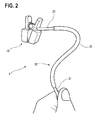
- Fig. 2 is a perspective view illustrating a state where the cable 20 having the above-described configuration is deformed.
- the figure illustrates the state where the second portion 22 is bent to exhibit a desired shape, and a part immediately below one end of the second portion 22 is nipped in fingertips so that the sensor body 10 is located above the fingertips.
- the second portion 22 retains the shape of the bent state based on the above-described second flexibility. Therefore, the cable 20 in the self-supported state supports the sensor body 10 in the illustrated position. If the cable is configured only by the first portion 21, the cable cannot support the weight of the sensor body 10 based on the first flexibility, and is downwardly bent.
- Fig. 3 is a perspective view showing a state where the sensor 1 having the above-described configuration is attached to the ear of the subject.
- the sensor body 10 clamps the earlobe 91 of the subject.
- the second portion 22 of the cable 20 goes around an upper portion 92 of the ear.
- the second portion 22 is bent and deformed into a shape which extends along the upper portion 92 of the ear.
- the second portion 22 can retain the shape in the bent state, and therefore the state where the portion is fitted to the upper portion 92 of the ear is maintained.
- the second portion 22 can be freely bent based on the second flexibility, and therefore deformed so as to extend along a desired portion of the body of the subject. Moreover, the second portion 22 can be deformed so as to extend along the body shape which varies from subject to subject. As a result, the cable 20 can be secured to a desired portion of the body of the subject. Furthermore, the second portion 22 can self-retain the bent shape based on the second flexibility, and therefore an adhesive tape or an additional securing device is not required in the securement. Consequently, it is possible to enhance the degree of freedom of selection of the place where the cable 20 of the sensor 1 for detecting biological information is to be secured.
- Fig. 4 is a perspective view illustrating a sensor 1A of a second embodiment of the invention.
- the components which are identical or similar to those of the sensor 1 of the first embodiment are denoted by the same reference numerals, and repeated description is omitted.
- the sensor 1A of the embodiment includes the sensor body 10 and a cable 20A.
- the cable 20A includes the first portion 21 and a second portion 22A.
- the second portion 22A is disposed so as to partly cover the first portion 21.
- the second portion 22A has the second flexibility which has been described in connection with the first embodiment.
- the second portion 22A includes large-diameter parts 23 and small-diameter parts 24.
- the second portion is formed so that the maximum diameter of the large-diameter parts 23 is larger than that of the small-diameter parts 24.
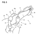
- Fig. 5 is a perspective view illustrating a state where the sensor 1A having the above-described configuration is attached to the fingertip of the subject.
- the sensor body 10 clamps the fingertip 93 of the subject.
- the second portion 22A of the cable 20A is wrapped around the finger 94.
- the second portion 22A is bent and deformed into a shape which spirally extends along the finger 94.
- the second portion 22A can retain the shape in the bent state, and therefore the state which is fitted to the finger 94 is maintained.
- Fig. 6 is a perspective view illustrating a state where the sensor 1A having the above-described configuration is attached to the ear of the subject.
- the sensor body 10 clamps the earlobe 91 of the subject.
- the second portion 22A of the cable 20A is hooked over the upper portion 92 of the ear.
- the second portion 22A is bent and deformed into a shape which extends along the upper portion 92 of the ear.
- the second portion 22A can retain the shape in the bent state, and therefore the state which is fitted to the upper portion 92 of the ear is maintained.
- a body portion of the subject to which the second portion 22A is attached has irregular convex and concave portions.
- difference in size formed between the large-diameter parts 23 and the small-diameter parts 24 can be easily caught by such irregular convex and concave portions, so that the cable 20A can be secured more surely to a body portion of the subject. Therefore, it is possible to enhance the degree of freedom of selection of the place where the cable 20A of the sensor 1A for detecting biological information is to be secured.
- the large-diameter parts 23 have a third flexibility.
- the third flexibility is higher than the first flexibility of the first portion 21.
- the large-diameter parts 23 are formed by a material such as a sponge, for example, it is possible to obtain a configuration having the third flexibility.
- the burden on the skin of the subject can be suppressed. Therefore, it is possible to enhance the degree of freedom of selection of the place where the cable 20A of the sensor 1A for detecting biological information is to be secured.
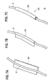
- Figs. 7A to 7C are perspective views illustrating a part of a sensor 1B of a third embodiment of the invention.
- the components which are identical or similar to those of the sensor 1 of the first embodiment are not illustrated or are denoted by the same reference numerals, and repeated description is omitted.
- the sensor 1B of the embodiment includes the sensor body 10 and a cable 20B.
- the cable 20B includes the first portion 21 and a second portion 22B.
- the second portion 22B is attachable to and detachable from the first portion 21.
- the second portion 22B has the second flexibility which has been described in connection with the first embodiment.
- the second portion 22B has a plate-like appearance.
- the second portion 22B is wrapped around a desired part of the first portion 21 as shown in Figs. 7B and 7C .
- the second portion 22B is configured so as to be able to self-retain a deformed shape. Therefore, the state where the second portion is wrapped around the desired part of the first portion 21 is maintained.
- a portion of the cable 20B in which a bent state must be retained can be arbitrarily set. Therefore, it is possible to enhance the degree of freedom of selection of the place where the cable 20B of the sensor 1B for detecting biological information is to be secured.
- the second portion 22B functions as a shape retainer that is to be attached to the cable of the sensor which to be attached to a living body to detect biological information, and that retains the shape of the cable to a desired state.
- Figs. 8A to 8C are perspective views illustrating a part of a sensor 1C of a fourth embodiment of the invention.
- the components which are identical or similar to those of the sensor 1 of the first embodiment are not illustrated or are denoted by the same reference numerals, and repeated description is omitted.
- the sensor 1C of the embodiment includes the sensor body 10 and a cable 20C.
- the cable 20C includes the first portion 21 and a second portion 22C.
- the second portion 22C is attachable to and detachable from the first portion 21.
- the second portion 22C has the second flexibility which has been described in connection with the first embodiment.
- the second portion 22C has a body 221 which has a tubular shape in the initial state, and a slit 222 is formed over the whole length. Because of the flexibility of the body 221, the slit 222 can be expandingly opened.
- a core line 223 is embedded in the whole length of the body 221.
- the core wire 223 is configured by a metal wire or like, and has the second flexibility. The flexibility of the body 221 is higher than that of the core wire 223.
- the slit 222 is expandingly opened, and a desired part of the first portion 21 is clamped by the second portion 22C as shown in Figs. 8B and 8C .
- the second portion 22C is configured so as to be able to self-retain a deformed shape. Therefore, the state where the second portion is wrapped around the desired part of the first portion 21 is maintained.
- a portion of the cable 20C in which a bent state must be retained can be arbitrarily set. Therefore, it is possible to enhance the degree of freedom of selection of the place where the cable 20C of the sensor 1C for detecting biological information is to be secured.
- the second portion 22C functions as a shape retainer that is attached to the cable of the sensor which to be attached to a living body to detect biological information, and that retains the shape of the cable to a desired state.
- the senor which is to be used as a probe of a pulse oximeter has been exemplarily shown.
- the invention can be applied to any adequate sensor which detects biological information, and which includes a cable transmitting a signal corresponding to the biological information.
- the portions of the large-diameter parts 23 having the maximum diameter, and those of the small-diameter parts 24 having the maximum diameter are continuous over respective constant zones to form the difference in size between the large-diameter parts 23 and the small-diameter parts 24.
- the second portion 22A may have a shape in which the outer diameter is continuously increased and decreased, and large-diameter parts and small-diameter parts are repeatedly formed.
- the second portion 22B in the third embodiment may be configured so as to have large-diameter parts and small-diameter parts as in the second portion 22A in the second embodiment.
- convex and concave portions may be formed in a part of the rear side (the side which is not opposed to the first portion 21) of the plate-like second portion 22B shown in Fig. 7A , and the second portion 22B is wrapped around so that the convex and concave portions are located in the outermost circumferential surface in the state shown in Fig. 7C .
- the second portion 22B in the third embodiment and the second portion 22C in the fourth embodiment are not always required to be attachable to and detachable from the first portion 21.
- an adhesive portion is disposed in an adequate place, it is possible to set a state where the second portion is permanently attached to the first portion 21.
- the second portion 22B in the third embodiment and the second portion 22C in the fourth embodiment are not always required to be attached to the cable of the sensor for detecting biological information.
- the shape retainer can be attached to an adequate cable for transmitting a signal. In a state where a cable of an electronic apparatus is bent, and secured to a desired place, for example, the shape retainer can retain the bent shape.
Landscapes
- Health & Medical Sciences (AREA)
- Life Sciences & Earth Sciences (AREA)
- Physics & Mathematics (AREA)
- Molecular Biology (AREA)
- Animal Behavior & Ethology (AREA)
- Pathology (AREA)
- Engineering & Computer Science (AREA)
- Biomedical Technology (AREA)
- Heart & Thoracic Surgery (AREA)
- Medical Informatics (AREA)
- Veterinary Medicine (AREA)
- Surgery (AREA)
- Biophysics (AREA)
- General Health & Medical Sciences (AREA)
- Public Health (AREA)
- Otolaryngology (AREA)
- Spectroscopy & Molecular Physics (AREA)
- Optics & Photonics (AREA)
- Cardiology (AREA)
- Physiology (AREA)
- Pulmonology (AREA)
- Measurement Of The Respiration, Hearing Ability, Form, And Blood Characteristics Of Living Organisms (AREA)
Abstract
Description
- The invention relates to a sensor which is attached to a living body to detect biological information, and also to a shape retainer which is attached to a cable for transmitting a signal corresponding to the biological information.
- When a cable connected to a sensor attached to a living body (subject) is in a freely swingable state, noises may be caused to enter a signal transmitted through the cable. Therefore, a procedure of securing the cable to the skin of the subject with an adhesive tape is sometimes performed. Alternatively, a sensor is sometimes used in which a securing device having a predetermined shape is attached to the cable (for example, see
JP-UM-A-7-028502 - In the case where the subject has sensitive skin, when a cable is secured to the skin with an adhesive tape, there is a possibility that the skin may become inflamed. Therefore, positions where securing with an adhesive tape may be performed are limited. The securing device disclosed in JP-UM-A-7-028502 has the predetermined shape corresponding to the attaching place of the body. Therefore, the degree of freedom of selection of the place where the cable is to be secured is low.
- Therefore, an object of the invention is to provide a technique for enhancing the degree of freedom of selection of the place where a cable of a sensor for detecting biological information is to be secured.
- In order to attain the object, a first aspect of the invention is a sensor which is attached to a living body, wherein the sensor includes:
- a sensor body configured to output a signal corresponding to biological information; and
- a cable configured to be connected to the sensor body and to transmit the signal,
- the cable has a first portion having a first flexibility, and a second portion having a second flexibility which is lower than the first flexibility, and
- the second flexibility enables the second portion to be bent and to retain a shape which is in a bent state.
- According to the configuration, the second portion can be freely bent based on the second flexibility, and therefore can be deformed so as to extend along a desired portion of the body of the subject. Moreover, the second portion can be deformed so as to extend along the body shape which varies from subject to subject. As a result, the cable can be secured to a desired portion of the body of the subject. Furthermore, the second portion can self-retain the bent shape based on the second flexibility, and therefore an adhesive tape or an additional securing device is not required in the securement. Consequently, it is possible to enhance the degree of freedom of selection of the place where the cable of the sensor for detecting biological information is to be secured.
- The second portion may include large-diameter parts having a first maximum diameter, and small-diameter parts having a second maximum diameter which is smaller than the first maximum diameter.
- Usually, a body portion of the subject to which the second portion is attached has irregular convex and concave portions. According to the configuration, difference in size formed between the large-diameter parts and the small-diameter parts can be easily caught by the irregular convex and concave portions, so that the cable can be secured more surely to a body portion of the subject. Therefore, it is possible to enhance the degree of freedom of selection of the place where the cable of the sensor for detecting biological information is to be secured.
- The large-diameter parts may be formed by a material having a third flexibility which is higher than the first flexibility.
- According to the configuration, even when the difference in size formed between the large-diameter parts and the small-diameter parts contact with a body portion of the subject, the burden on the skin of the subject can be suppressed. Therefore, it is possible to enhance the degree of freedom of selection of the place where the cable of the sensor for detecting biological information is to be secured.
- The second portion may be attachable to and detachable from the first portion.
- The second portion also may have a core line embedded in the whole length of the second portion in a longitudinal direction of the second portion.
- According to the configuration, in accordance with the shape of a body portion of the subject to which the cable is to be secured, a portion of the cable in which a bent state must be retained can be arbitrarily set. Therefore, it is possible to enhance the degree of freedom of selection of the place where the cable of the sensor for detecting biological information is to be secured.
- In this case, the second portion functions as a shape retainer that is attached to the cable of the sensor which is attached to a living body to detect biological information, and that retains the shape of the cable to a desired state.
- In order to attain the object, therefore, a second aspect of the invention is a shape retainer attached to a cable for transmitting a signal, wherein
the shape retainer has a second flexibility which is lower than a first flexibility of the cable, and
the second flexibility allows the retainer to be bent and to retain a shape which is in a bent state. - The shape retainer can be attached to an adequate cable for transmitting a signal. In a state where a cable of an electronic apparatus is bent, and secured to a desired place, for example, the shape retainer can retain the bent shape.
-
-
Fig. 1 is a perspective view illustrating a sensor of a first embodiment of the invention. -
Fig. 2 is a perspective view illustrating a state where a cable of the sensor ofFig. 1 is deformed. -
Fig. 3 is a perspective view illustrating a state where the sensor ofFig. 1 is attached to the ear of the subject. -
Fig. 4 is a perspective view illustrating a sensor of a second embodiment of the invention. -
Fig. 5 is a perspective view illustrating a state where the sensor ofFig. 4 is attached to a finger of the subject. -
Fig. 6 is a perspective view illustrating a state where the sensor ofFig. 4 is attached to the ear of the subject. -
Figs. 7A to 7C are perspective views illustrating a part of a sensor of a third embodiment of the invention. -
Figs. 8A to 8C are perspective views illustrating a part of a sensor of a fourth embodiment of the invention. - Hereinafter, embodiments of the invention will be described in detail with reference to the accompanying drawings. In the drawings which will be used in the following description, the scale is adequately changed in order to draw components in a recognizable size.
-
Fig. 1 is a perspective view illustrating a sensor 1 of a first embodiment of the invention. The sensor 1 attached to a living body (subject) can include asensor body 10 and acable 20. The sensor 1 is used as a probe of a pulse oximeter. - The
sensor body 10 has a clip-like shape, and is configured so as to be able to clamp a portion (fingertip, earlobe, or the like) of the body of the subject. Thesensor body 10 can include alight emitter 11 and alight detector 12. Thelight emitter 11 is configured so as to emit a red light and an infrared light. Thelight detector 12 is configured so as to output signals corresponding to the intensities of the light which have been passed through the body part of the subject clamped by thesensor body 10. - In hemoglobin in blood, absorbances of a red light and an infrared light are different from each other depending on presence or absence of oxygenation. When the intensities of the light detected by the
light detector 12 are analyzed, therefore, it is possible to measure the arterial oxygen saturation (SpO2). When the pulse wave component due to the pulsation of the heart is detected, it is possible to measure the heart rate. Namely, thesensor body 10 outputs signals corresponding respectively to the SpO2 and heart rate which are examples of biological information. - The
cable 20 transmits the signals output from thelight detector 12 to the pulse oximeter which is not shown. The pulse oximeter measures the SpO2 and heart rate which are described above, based on the transmitted signals. - The
cable 20 can include afirst portion 21 and asecond portion 22. One end of thefirst portion 21 is connected to thelight detector 12, and the other end of thefirst portion 21 is connected to the pulse oximeter. - The
first portion 21 has a first flexibility. The first flexibility is at a degree which enables the first portion to be bent, and which disables the first portion to retain the shape in a bent state. - The
second portion 22 is disposed so as to partly cover thefirst portion 21. Thesecond portion 22 has a second flexibility. The second flexibility is lower than the first flexibility. The second flexibility is at a degree which enables the second portion to be bent, and which enables the second portion to retain the shape in a bent state. -
Fig. 2 is a perspective view illustrating a state where thecable 20 having the above-described configuration is deformed. The figure illustrates the state where thesecond portion 22 is bent to exhibit a desired shape, and a part immediately below one end of thesecond portion 22 is nipped in fingertips so that thesensor body 10 is located above the fingertips. - The
second portion 22 retains the shape of the bent state based on the above-described second flexibility. Therefore, thecable 20 in the self-supported state supports thesensor body 10 in the illustrated position. If the cable is configured only by thefirst portion 21, the cable cannot support the weight of thesensor body 10 based on the first flexibility, and is downwardly bent. -
Fig. 3 is a perspective view showing a state where the sensor 1 having the above-described configuration is attached to the ear of the subject. Thesensor body 10 clamps theearlobe 91 of the subject. Thesecond portion 22 of thecable 20 goes around anupper portion 92 of the ear. Thesecond portion 22 is bent and deformed into a shape which extends along theupper portion 92 of the ear. Thesecond portion 22 can retain the shape in the bent state, and therefore the state where the portion is fitted to theupper portion 92 of the ear is maintained. - The
second portion 22 can be freely bent based on the second flexibility, and therefore deformed so as to extend along a desired portion of the body of the subject. Moreover, thesecond portion 22 can be deformed so as to extend along the body shape which varies from subject to subject. As a result, thecable 20 can be secured to a desired portion of the body of the subject. Furthermore, thesecond portion 22 can self-retain the bent shape based on the second flexibility, and therefore an adhesive tape or an additional securing device is not required in the securement. Consequently, it is possible to enhance the degree of freedom of selection of the place where thecable 20 of the sensor 1 for detecting biological information is to be secured. -
Fig. 4 is a perspective view illustrating asensor 1A of a second embodiment of the invention. The components which are identical or similar to those of the sensor 1 of the first embodiment are denoted by the same reference numerals, and repeated description is omitted. - The
sensor 1A of the embodiment includes thesensor body 10 and acable 20A. Thecable 20A includes thefirst portion 21 and asecond portion 22A. Thesecond portion 22A is disposed so as to partly cover thefirst portion 21. Thesecond portion 22A has the second flexibility which has been described in connection with the first embodiment. - The
second portion 22A includes large-diameter parts 23 and small-diameter parts 24. The second portion is formed so that the maximum diameter of the large-diameter parts 23 is larger than that of the small-diameter parts 24. -
Fig. 5 is a perspective view illustrating a state where thesensor 1A having the above-described configuration is attached to the fingertip of the subject. Thesensor body 10 clamps thefingertip 93 of the subject. Thesecond portion 22A of thecable 20A is wrapped around thefinger 94. Thesecond portion 22A is bent and deformed into a shape which spirally extends along thefinger 94. Thesecond portion 22A can retain the shape in the bent state, and therefore the state which is fitted to thefinger 94 is maintained. -
Fig. 6 is a perspective view illustrating a state where thesensor 1A having the above-described configuration is attached to the ear of the subject. Thesensor body 10 clamps theearlobe 91 of the subject. Thesecond portion 22A of thecable 20A is hooked over theupper portion 92 of the ear. Thesecond portion 22A is bent and deformed into a shape which extends along theupper portion 92 of the ear. Thesecond portion 22A can retain the shape in the bent state, and therefore the state which is fitted to theupper portion 92 of the ear is maintained. - Generally, a body portion of the subject to which the
second portion 22A is attached has irregular convex and concave portions. According to the configuration of the embodiment, difference in size formed between the large-diameter parts 23 and the small-diameter parts 24 can be easily caught by such irregular convex and concave portions, so that thecable 20A can be secured more surely to a body portion of the subject. Therefore, it is possible to enhance the degree of freedom of selection of the place where thecable 20A of thesensor 1A for detecting biological information is to be secured. - The large-
diameter parts 23 have a third flexibility. The third flexibility is higher than the first flexibility of thefirst portion 21. When the large-diameter parts 23 are formed by a material such as a sponge, for example, it is possible to obtain a configuration having the third flexibility. - According to the configuration, even when the difference in size formed between the large-
diameter parts 23 and the small-diameter parts 24 contact with a body portion of the subject, the burden on the skin of the subject can be suppressed. Therefore, it is possible to enhance the degree of freedom of selection of the place where thecable 20A of thesensor 1A for detecting biological information is to be secured. -
Figs. 7A to 7C are perspective views illustrating a part of asensor 1B of a third embodiment of the invention. The components which are identical or similar to those of the sensor 1 of the first embodiment are not illustrated or are denoted by the same reference numerals, and repeated description is omitted. - As shown in
Fig. 7C , thesensor 1B of the embodiment includes thesensor body 10 and acable 20B. Thecable 20B includes thefirst portion 21 and asecond portion 22B. Thesecond portion 22B is attachable to and detachable from thefirst portion 21. Thesecond portion 22B has the second flexibility which has been described in connection with the first embodiment. - As shown in
Fig. 7A , in the initial state, thesecond portion 22B has a plate-like appearance. When the thus configuredsecond portion 22B is attached to thefirst portion 21, thesecond portion 22B is wrapped around a desired part of thefirst portion 21 as shown inFigs. 7B and 7C . Thesecond portion 22B is configured so as to be able to self-retain a deformed shape. Therefore, the state where the second portion is wrapped around the desired part of thefirst portion 21 is maintained. - According to the configuration, in accordance with the shape of a body portion of the subject to which the
cable 20B is to be secured, a portion of thecable 20B in which a bent state must be retained can be arbitrarily set. Therefore, it is possible to enhance the degree of freedom of selection of the place where thecable 20B of thesensor 1B for detecting biological information is to be secured. - In this case, the
second portion 22B functions as a shape retainer that is to be attached to the cable of the sensor which to be attached to a living body to detect biological information, and that retains the shape of the cable to a desired state. -
Figs. 8A to 8C are perspective views illustrating a part of a sensor 1C of a fourth embodiment of the invention. The components which are identical or similar to those of the sensor 1 of the first embodiment are not illustrated or are denoted by the same reference numerals, and repeated description is omitted. - As shown in
Fig. 8C , the sensor 1C of the embodiment includes thesensor body 10 and a cable 20C. The cable 20C includes thefirst portion 21 and asecond portion 22C. Thesecond portion 22C is attachable to and detachable from thefirst portion 21. Thesecond portion 22C has the second flexibility which has been described in connection with the first embodiment. - As shown in
Fig. 8A , thesecond portion 22C has abody 221 which has a tubular shape in the initial state, and aslit 222 is formed over the whole length. Because of the flexibility of thebody 221, theslit 222 can be expandingly opened. Acore line 223 is embedded in the whole length of thebody 221. Thecore wire 223 is configured by a metal wire or like, and has the second flexibility. The flexibility of thebody 221 is higher than that of thecore wire 223. - When the thus configured
second portion 22C is to be attached to thefirst portion 21, theslit 222 is expandingly opened, and a desired part of thefirst portion 21 is clamped by thesecond portion 22C as shown inFigs. 8B and 8C . Thesecond portion 22C is configured so as to be able to self-retain a deformed shape. Therefore, the state where the second portion is wrapped around the desired part of thefirst portion 21 is maintained. - According to the configuration, in accordance with the shape of a body portion of the subject to which the cable 20C is to be secured, a portion of the cable 20C in which a bent state must be retained can be arbitrarily set. Therefore, it is possible to enhance the degree of freedom of selection of the place where the cable 20C of the sensor 1C for detecting biological information is to be secured.
- In this case, the
second portion 22C functions as a shape retainer that is attached to the cable of the sensor which to be attached to a living body to detect biological information, and that retains the shape of the cable to a desired state. - The embodiments have been described in order to facilitate understanding of the invention, and are not intended to limit the invention. It is a matter of course that the invention may be changed or improved without departing the spirit thereof, and includes equivalent embodiments.
- In the embodiments described above, the sensor which is to be used as a probe of a pulse oximeter has been exemplarily shown. However, the invention can be applied to any adequate sensor which detects biological information, and which includes a cable transmitting a signal corresponding to the biological information.
- In the
second portion 22A in the second embodiment, the portions of the large-diameter parts 23 having the maximum diameter, and those of the small-diameter parts 24 having the maximum diameter are continuous over respective constant zones to form the difference in size between the large-diameter parts 23 and the small-diameter parts 24. Alternatively, thesecond portion 22A may have a shape in which the outer diameter is continuously increased and decreased, and large-diameter parts and small-diameter parts are repeatedly formed. - The
second portion 22B in the third embodiment may be configured so as to have large-diameter parts and small-diameter parts as in thesecond portion 22A in the second embodiment. For example, convex and concave portions may be formed in a part of the rear side (the side which is not opposed to the first portion 21) of the plate-likesecond portion 22B shown inFig. 7A , and thesecond portion 22B is wrapped around so that the convex and concave portions are located in the outermost circumferential surface in the state shown inFig. 7C . - The
second portion 22B in the third embodiment and thesecond portion 22C in the fourth embodiment are not always required to be attachable to and detachable from thefirst portion 21. When an adhesive portion is disposed in an adequate place, it is possible to set a state where the second portion is permanently attached to thefirst portion 21. - The
second portion 22B in the third embodiment and thesecond portion 22C in the fourth embodiment are not always required to be attached to the cable of the sensor for detecting biological information. The shape retainer can be attached to an adequate cable for transmitting a signal. In a state where a cable of an electronic apparatus is bent, and secured to a desired place, for example, the shape retainer can retain the bent shape. - 1, 1A, 1B:
- sensor
- 10:
- sensor body
- 20:
- cable
- 21:
- first portion
- 22, 22A:
- second portion
- 22B:
- second portion (shape retainer)
- 23:
- large-diameter part
- 24:
- small-diameter part
Claims (7)
- A sensor which is attached to a living body comprising:a sensor body configured to output a signal corresponding to biological information; anda cable configured to be connected to the sensor body and to transmit the signal,wherein the cable has a first portion having a first flexibility and a second portion having a second flexibility which is lower than the first flexibility, andthe second flexibility enables the second portion to be bent and to retain a shape of the second portion in a bent state.
- The sensor according to claim 1, wherein the second portion includes large-diameter parts having a first maximum diameter and a small-diameter part having a second maximum diameter which is smaller than the first maximum diameter.
- The sensor according to claim 2, wherein the large-diameter parts are formed by a material having a third flexibility which is higher than the first flexibility.
- The sensor according to any one of claims 1 to 3, wherein the second portion is attachable to and detachable from the first portion.
- The sensor according to claim 1, wherein the second portion having a core line which is embedded in the whole length of the second portion in a longitudinal direction of the second portion.
- A shape retainer attached to a cable for transmitting a signal,
wherein the shape retainer has a second flexibility which is lower than a first flexibility of the cable, and
the second flexibility allows the retainer to be bent and to retain a shape which is in a bent state. - The shape retainer according to claim 6, wherein the shape retainer is attachable to and detachable from the cable.
Applications Claiming Priority (1)
| Application Number | Priority Date | Filing Date | Title |
|---|---|---|---|
| JP2013212863A JP6189705B2 (en) | 2013-10-10 | 2013-10-10 | Sensor and shape holder |
Publications (2)
| Publication Number | Publication Date |
|---|---|
| EP2859846A1 true EP2859846A1 (en) | 2015-04-15 |
| EP2859846B1 EP2859846B1 (en) | 2019-05-01 |
Family
ID=51868749
Family Applications (1)
| Application Number | Title | Priority Date | Filing Date |
|---|---|---|---|
| EP14187000.6A Active EP2859846B1 (en) | 2013-10-10 | 2014-09-30 | Sensor and shape retainer |
Country Status (4)
| Country | Link |
|---|---|
| US (1) | US9844342B2 (en) |
| EP (1) | EP2859846B1 (en) |
| JP (1) | JP6189705B2 (en) |
| CN (1) | CN104545941A (en) |
Families Citing this family (6)
| Publication number | Priority date | Publication date | Assignee | Title |
|---|---|---|---|---|
| US9502349B2 (en) | 2014-01-17 | 2016-11-22 | Macronix International Co., Ltd. | Separated lower select line in 3D NAND architecture |
| US9437605B2 (en) | 2012-12-24 | 2016-09-06 | Macronix International Co., Ltd. | 3D NAND array architecture |
| US9679849B1 (en) | 2014-01-17 | 2017-06-13 | Macronix International Co., Ltd. | 3D NAND array with sides having undulating shapes |
| US9373632B2 (en) | 2014-01-17 | 2016-06-21 | Macronix International Co., Ltd. | Twisted array design for high speed vertical channel 3D NAND memory |
| JP2019068920A (en) * | 2017-10-06 | 2019-05-09 | 日本光電工業株式会社 | Cable guide and detection device with cable guide |
| US11037947B2 (en) | 2019-04-15 | 2021-06-15 | Macronix International Co., Ltd. | Array of pillars located in a uniform pattern |
Citations (6)
| Publication number | Priority date | Publication date | Assignee | Title |
|---|---|---|---|---|
| US5461200A (en) * | 1994-06-13 | 1995-10-24 | Norcia; James | Compliant stiffener for long flexible members |
| US20040054291A1 (en) * | 2002-09-14 | 2004-03-18 | Christian Schulz | Pulse oximetry ear sensor |
| WO2009147370A1 (en) * | 2008-06-03 | 2009-12-10 | Racal Acoustics Limited | Earpieces |
| US20100256460A1 (en) * | 2009-04-03 | 2010-10-07 | The General Electric Company | Wearable Monitoring System |
| US20120253159A1 (en) * | 2011-03-31 | 2012-10-04 | Nellcor Puritan Bennett Llc | Moldable ear sensor |
| JP2012244515A (en) * | 2011-05-23 | 2012-12-10 | Jvc Kenwood Corp | Ear-hook hanger, earphone, and manufacturing method of the earphone |
Family Cites Families (10)
| Publication number | Priority date | Publication date | Assignee | Title |
|---|---|---|---|---|
| US5386489A (en) * | 1993-01-05 | 1995-01-31 | Christine E. Munson | Deformable shape-retaining fiberoptic device |
| JPH0670395U (en) * | 1993-03-10 | 1994-09-30 | アイワ株式会社 | Cord storage device such as headphone device |
| JPH0728502U (en) | 1993-06-21 | 1995-05-30 | セノー株式会社 | Ear sensor for pulse wave detection |
| JPH0879875A (en) * | 1994-09-01 | 1996-03-22 | Metoritsukusu:Kk | Portable earphone |
| US6874908B2 (en) * | 2002-05-13 | 2005-04-05 | Streamlight, Inc. | Flexible bendable flashlight |
| JP2004180252A (en) * | 2002-11-28 | 2004-06-24 | Toshiaki Ichige | Decoration fitting for earphone code and earphone code |
| JP2009194790A (en) * | 2008-02-18 | 2009-08-27 | Isao Tazaki | Earphone accessory |
| JP5801623B2 (en) * | 2011-06-29 | 2015-10-28 | エス・ディ・ケイ株式会社 | Sheathed wire |
| JP2013013540A (en) * | 2011-07-04 | 2013-01-24 | Sony Corp | Auricle-installed apparatus |
| US20150041173A1 (en) * | 2013-08-09 | 2015-02-12 | Peter Chin | Cable management device |
-
2013
- 2013-10-10 JP JP2013212863A patent/JP6189705B2/en active Active
-
2014
- 2014-09-18 US US14/489,532 patent/US9844342B2/en active Active
- 2014-09-30 EP EP14187000.6A patent/EP2859846B1/en active Active
- 2014-10-08 CN CN201410524560.7A patent/CN104545941A/en active Pending
Patent Citations (6)
| Publication number | Priority date | Publication date | Assignee | Title |
|---|---|---|---|---|
| US5461200A (en) * | 1994-06-13 | 1995-10-24 | Norcia; James | Compliant stiffener for long flexible members |
| US20040054291A1 (en) * | 2002-09-14 | 2004-03-18 | Christian Schulz | Pulse oximetry ear sensor |
| WO2009147370A1 (en) * | 2008-06-03 | 2009-12-10 | Racal Acoustics Limited | Earpieces |
| US20100256460A1 (en) * | 2009-04-03 | 2010-10-07 | The General Electric Company | Wearable Monitoring System |
| US20120253159A1 (en) * | 2011-03-31 | 2012-10-04 | Nellcor Puritan Bennett Llc | Moldable ear sensor |
| JP2012244515A (en) * | 2011-05-23 | 2012-12-10 | Jvc Kenwood Corp | Ear-hook hanger, earphone, and manufacturing method of the earphone |
Also Published As
| Publication number | Publication date |
|---|---|
| US9844342B2 (en) | 2017-12-19 |
| EP2859846B1 (en) | 2019-05-01 |
| JP6189705B2 (en) | 2017-08-30 |
| JP2015073784A (en) | 2015-04-20 |
| US20150105639A1 (en) | 2015-04-16 |
| CN104545941A (en) | 2015-04-29 |
Similar Documents
| Publication | Publication Date | Title |
|---|---|---|
| US9844342B2 (en) | Sensor and shape retainer | |
| US20150005600A1 (en) | Finger-placement sensor tape | |
| US10342486B2 (en) | Clip sensor device for measurement of vital signs | |
| JP6524867B2 (en) | Neck band type biological information detector | |
| US20060224054A1 (en) | Pulse wave detecting device and method therefor | |
| US9770198B2 (en) | Sensor and fastener | |
| CN107847190A (en) | For keeping the apparatus of biosensor | |
| EP2886045A1 (en) | Biological signal measuring system | |
| KR20080069851A (en) | Biological signal measuring sensor device and headset device and pendant device having said sensor device | |
| US20120136228A1 (en) | Method of informing sensor mounting time period and apparatus for informing sensor mounting time period | |
| WO2017086072A1 (en) | Pulse wave propagation time measurement device and biological state estimation device | |
| CN108024749A (en) | Biological information measurement utensil | |
| US11147512B2 (en) | Pulse wave detection device and biometric information measurement device | |
| JP2020511256A5 (en) | ||
| JP6191977B1 (en) | Biological information measurement system and biological information measurement method | |
| TW200618773A (en) | Integrated biosignal measuring apparatus | |
| JP2013000540A (en) | Pulse wave detector, and pulse wave detection system | |
| KR20160012664A (en) | Wrist Support united wireless mouse and stress measuring system | |
| US10117619B2 (en) | Optical sensor | |
| US20150257664A1 (en) | Heart monitoring sensor | |
| KR20110136113A (en) | Portable bio signal measuring device | |
| JPH09215664A (en) | Evaluator of autonomic nerve function | |
| CN209122243U (en) | Blood oxygen saturation detection device and oximeter monitor system | |
| JP6904746B2 (en) | Sensor | |
| JP2005095615A (en) | Confirmation method and confirmation device for emotional changes in subjects |
Legal Events
| Date | Code | Title | Description |
|---|---|---|---|
| PUAI | Public reference made under article 153(3) epc to a published international application that has entered the european phase |
Free format text: ORIGINAL CODE: 0009012 |
|
| 17P | Request for examination filed |
Effective date: 20140930 |
|
| AK | Designated contracting states |
Kind code of ref document: A1 Designated state(s): AL AT BE BG CH CY CZ DE DK EE ES FI FR GB GR HR HU IE IS IT LI LT LU LV MC MK MT NL NO PL PT RO RS SE SI SK SM TR |
|
| AX | Request for extension of the european patent |
Extension state: BA ME |
|
| R17P | Request for examination filed (corrected) |
Effective date: 20151013 |
|
| RBV | Designated contracting states (corrected) |
Designated state(s): AL AT BE BG CH CY CZ DE DK EE ES FI FR GB GR HR HU IE IS IT LI LT LU LV MC MK MT NL NO PL PT RO RS SE SI SK SM TR |
|
| STAA | Information on the status of an ep patent application or granted ep patent |
Free format text: STATUS: EXAMINATION IS IN PROGRESS |
|
| 17Q | First examination report despatched |
Effective date: 20170111 |
|
| RIC1 | Information provided on ipc code assigned before grant |
Ipc: A61B 5/1455 20060101AFI20180913BHEP Ipc: B60R 16/02 20060101ALN20180913BHEP Ipc: A61B 5/024 20060101ALN20180913BHEP |
|
| RIC1 | Information provided on ipc code assigned before grant |
Ipc: A61B 5/1455 20060101AFI20180919BHEP Ipc: B60R 16/02 20060101ALN20180919BHEP Ipc: A61B 5/024 20060101ALN20180919BHEP |
|
| GRAP | Despatch of communication of intention to grant a patent |
Free format text: ORIGINAL CODE: EPIDOSNIGR1 |
|
| STAA | Information on the status of an ep patent application or granted ep patent |
Free format text: STATUS: GRANT OF PATENT IS INTENDED |
|
| RIC1 | Information provided on ipc code assigned before grant |
Ipc: A61B 5/1455 20060101AFI20181112BHEP Ipc: B60R 16/02 20060101ALN20181112BHEP Ipc: A61B 5/024 20060101ALN20181112BHEP |
|
| INTG | Intention to grant announced |
Effective date: 20181203 |
|
| GRAS | Grant fee paid |
Free format text: ORIGINAL CODE: EPIDOSNIGR3 |
|
| GRAA | (expected) grant |
Free format text: ORIGINAL CODE: 0009210 |
|
| STAA | Information on the status of an ep patent application or granted ep patent |
Free format text: STATUS: THE PATENT HAS BEEN GRANTED |
|
| AK | Designated contracting states |
Kind code of ref document: B1 Designated state(s): AL AT BE BG CH CY CZ DE DK EE ES FI FR GB GR HR HU IE IS IT LI LT LU LV MC MK MT NL NO PL PT RO RS SE SI SK SM TR |
|
| REG | Reference to a national code |
Ref country code: GB Ref legal event code: FG4D |
|
| REG | Reference to a national code |
Ref country code: CH Ref legal event code: EP Ref country code: AT Ref legal event code: REF Ref document number: 1125822 Country of ref document: AT Kind code of ref document: T Effective date: 20190515 |
|
| REG | Reference to a national code |
Ref country code: DE Ref legal event code: R096 Ref document number: 602014045658 Country of ref document: DE |
|
| REG | Reference to a national code |
Ref country code: IE Ref legal event code: FG4D |
|
| REG | Reference to a national code |
Ref country code: NL Ref legal event code: MP Effective date: 20190501 |
|
| REG | Reference to a national code |
Ref country code: LT Ref legal event code: MG4D |
|
| PG25 | Lapsed in a contracting state [announced via postgrant information from national office to epo] |
Ref country code: FI Free format text: LAPSE BECAUSE OF FAILURE TO SUBMIT A TRANSLATION OF THE DESCRIPTION OR TO PAY THE FEE WITHIN THE PRESCRIBED TIME-LIMIT Effective date: 20190501 Ref country code: ES Free format text: LAPSE BECAUSE OF FAILURE TO SUBMIT A TRANSLATION OF THE DESCRIPTION OR TO PAY THE FEE WITHIN THE PRESCRIBED TIME-LIMIT Effective date: 20190501 Ref country code: NO Free format text: LAPSE BECAUSE OF FAILURE TO SUBMIT A TRANSLATION OF THE DESCRIPTION OR TO PAY THE FEE WITHIN THE PRESCRIBED TIME-LIMIT Effective date: 20190801 Ref country code: AL Free format text: LAPSE BECAUSE OF FAILURE TO SUBMIT A TRANSLATION OF THE DESCRIPTION OR TO PAY THE FEE WITHIN THE PRESCRIBED TIME-LIMIT Effective date: 20190501 Ref country code: PT Free format text: LAPSE BECAUSE OF FAILURE TO SUBMIT A TRANSLATION OF THE DESCRIPTION OR TO PAY THE FEE WITHIN THE PRESCRIBED TIME-LIMIT Effective date: 20190901 Ref country code: SE Free format text: LAPSE BECAUSE OF FAILURE TO SUBMIT A TRANSLATION OF THE DESCRIPTION OR TO PAY THE FEE WITHIN THE PRESCRIBED TIME-LIMIT Effective date: 20190501 Ref country code: HR Free format text: LAPSE BECAUSE OF FAILURE TO SUBMIT A TRANSLATION OF THE DESCRIPTION OR TO PAY THE FEE WITHIN THE PRESCRIBED TIME-LIMIT Effective date: 20190501 Ref country code: NL Free format text: LAPSE BECAUSE OF FAILURE TO SUBMIT A TRANSLATION OF THE DESCRIPTION OR TO PAY THE FEE WITHIN THE PRESCRIBED TIME-LIMIT Effective date: 20190501 Ref country code: LT Free format text: LAPSE BECAUSE OF FAILURE TO SUBMIT A TRANSLATION OF THE DESCRIPTION OR TO PAY THE FEE WITHIN THE PRESCRIBED TIME-LIMIT Effective date: 20190501 |
|
| PG25 | Lapsed in a contracting state [announced via postgrant information from national office to epo] |
Ref country code: LV Free format text: LAPSE BECAUSE OF FAILURE TO SUBMIT A TRANSLATION OF THE DESCRIPTION OR TO PAY THE FEE WITHIN THE PRESCRIBED TIME-LIMIT Effective date: 20190501 Ref country code: RS Free format text: LAPSE BECAUSE OF FAILURE TO SUBMIT A TRANSLATION OF THE DESCRIPTION OR TO PAY THE FEE WITHIN THE PRESCRIBED TIME-LIMIT Effective date: 20190501 Ref country code: BG Free format text: LAPSE BECAUSE OF FAILURE TO SUBMIT A TRANSLATION OF THE DESCRIPTION OR TO PAY THE FEE WITHIN THE PRESCRIBED TIME-LIMIT Effective date: 20190801 Ref country code: GR Free format text: LAPSE BECAUSE OF FAILURE TO SUBMIT A TRANSLATION OF THE DESCRIPTION OR TO PAY THE FEE WITHIN THE PRESCRIBED TIME-LIMIT Effective date: 20190802 |
|
| REG | Reference to a national code |
Ref country code: AT Ref legal event code: MK05 Ref document number: 1125822 Country of ref document: AT Kind code of ref document: T Effective date: 20190501 |
|
| PG25 | Lapsed in a contracting state [announced via postgrant information from national office to epo] |
Ref country code: IS Free format text: LAPSE BECAUSE OF FAILURE TO SUBMIT A TRANSLATION OF THE DESCRIPTION OR TO PAY THE FEE WITHIN THE PRESCRIBED TIME-LIMIT Effective date: 20190901 |
|
| PG25 | Lapsed in a contracting state [announced via postgrant information from national office to epo] |
Ref country code: SK Free format text: LAPSE BECAUSE OF FAILURE TO SUBMIT A TRANSLATION OF THE DESCRIPTION OR TO PAY THE FEE WITHIN THE PRESCRIBED TIME-LIMIT Effective date: 20190501 Ref country code: EE Free format text: LAPSE BECAUSE OF FAILURE TO SUBMIT A TRANSLATION OF THE DESCRIPTION OR TO PAY THE FEE WITHIN THE PRESCRIBED TIME-LIMIT Effective date: 20190501 Ref country code: DK Free format text: LAPSE BECAUSE OF FAILURE TO SUBMIT A TRANSLATION OF THE DESCRIPTION OR TO PAY THE FEE WITHIN THE PRESCRIBED TIME-LIMIT Effective date: 20190501 Ref country code: AT Free format text: LAPSE BECAUSE OF FAILURE TO SUBMIT A TRANSLATION OF THE DESCRIPTION OR TO PAY THE FEE WITHIN THE PRESCRIBED TIME-LIMIT Effective date: 20190501 Ref country code: CZ Free format text: LAPSE BECAUSE OF FAILURE TO SUBMIT A TRANSLATION OF THE DESCRIPTION OR TO PAY THE FEE WITHIN THE PRESCRIBED TIME-LIMIT Effective date: 20190501 Ref country code: RO Free format text: LAPSE BECAUSE OF FAILURE TO SUBMIT A TRANSLATION OF THE DESCRIPTION OR TO PAY THE FEE WITHIN THE PRESCRIBED TIME-LIMIT Effective date: 20190501 |
|
| REG | Reference to a national code |
Ref country code: DE Ref legal event code: R097 Ref document number: 602014045658 Country of ref document: DE |
|
| PG25 | Lapsed in a contracting state [announced via postgrant information from national office to epo] |
Ref country code: IT Free format text: LAPSE BECAUSE OF FAILURE TO SUBMIT A TRANSLATION OF THE DESCRIPTION OR TO PAY THE FEE WITHIN THE PRESCRIBED TIME-LIMIT Effective date: 20190501 Ref country code: SM Free format text: LAPSE BECAUSE OF FAILURE TO SUBMIT A TRANSLATION OF THE DESCRIPTION OR TO PAY THE FEE WITHIN THE PRESCRIBED TIME-LIMIT Effective date: 20190501 |
|
| PLBE | No opposition filed within time limit |
Free format text: ORIGINAL CODE: 0009261 |
|
| STAA | Information on the status of an ep patent application or granted ep patent |
Free format text: STATUS: NO OPPOSITION FILED WITHIN TIME LIMIT |
|
| PG25 | Lapsed in a contracting state [announced via postgrant information from national office to epo] |
Ref country code: TR Free format text: LAPSE BECAUSE OF FAILURE TO SUBMIT A TRANSLATION OF THE DESCRIPTION OR TO PAY THE FEE WITHIN THE PRESCRIBED TIME-LIMIT Effective date: 20190501 |
|
| 26N | No opposition filed |
Effective date: 20200204 |
|
| PG25 | Lapsed in a contracting state [announced via postgrant information from national office to epo] |
Ref country code: PL Free format text: LAPSE BECAUSE OF FAILURE TO SUBMIT A TRANSLATION OF THE DESCRIPTION OR TO PAY THE FEE WITHIN THE PRESCRIBED TIME-LIMIT Effective date: 20190501 |
|
| PG25 | Lapsed in a contracting state [announced via postgrant information from national office to epo] |
Ref country code: SI Free format text: LAPSE BECAUSE OF FAILURE TO SUBMIT A TRANSLATION OF THE DESCRIPTION OR TO PAY THE FEE WITHIN THE PRESCRIBED TIME-LIMIT Effective date: 20190501 Ref country code: MC Free format text: LAPSE BECAUSE OF FAILURE TO SUBMIT A TRANSLATION OF THE DESCRIPTION OR TO PAY THE FEE WITHIN THE PRESCRIBED TIME-LIMIT Effective date: 20190501 |
|
| REG | Reference to a national code |
Ref country code: CH Ref legal event code: PL |
|
| PG25 | Lapsed in a contracting state [announced via postgrant information from national office to epo] |
Ref country code: LI Free format text: LAPSE BECAUSE OF NON-PAYMENT OF DUE FEES Effective date: 20190930 Ref country code: CH Free format text: LAPSE BECAUSE OF NON-PAYMENT OF DUE FEES Effective date: 20190930 Ref country code: LU Free format text: LAPSE BECAUSE OF NON-PAYMENT OF DUE FEES Effective date: 20190930 Ref country code: IE Free format text: LAPSE BECAUSE OF NON-PAYMENT OF DUE FEES Effective date: 20190930 |
|
| REG | Reference to a national code |
Ref country code: BE Ref legal event code: MM Effective date: 20190930 |
|
| PG25 | Lapsed in a contracting state [announced via postgrant information from national office to epo] |
Ref country code: BE Free format text: LAPSE BECAUSE OF NON-PAYMENT OF DUE FEES Effective date: 20190930 |
|
| GBPC | Gb: european patent ceased through non-payment of renewal fee |
Effective date: 20190930 |
|
| PG25 | Lapsed in a contracting state [announced via postgrant information from national office to epo] |
Ref country code: FR Free format text: LAPSE BECAUSE OF NON-PAYMENT OF DUE FEES Effective date: 20190930 Ref country code: GB Free format text: LAPSE BECAUSE OF NON-PAYMENT OF DUE FEES Effective date: 20190930 |
|
| PG25 | Lapsed in a contracting state [announced via postgrant information from national office to epo] |
Ref country code: CY Free format text: LAPSE BECAUSE OF FAILURE TO SUBMIT A TRANSLATION OF THE DESCRIPTION OR TO PAY THE FEE WITHIN THE PRESCRIBED TIME-LIMIT Effective date: 20190501 |
|
| PG25 | Lapsed in a contracting state [announced via postgrant information from national office to epo] |
Ref country code: HU Free format text: LAPSE BECAUSE OF FAILURE TO SUBMIT A TRANSLATION OF THE DESCRIPTION OR TO PAY THE FEE WITHIN THE PRESCRIBED TIME-LIMIT; INVALID AB INITIO Effective date: 20140930 Ref country code: MT Free format text: LAPSE BECAUSE OF FAILURE TO SUBMIT A TRANSLATION OF THE DESCRIPTION OR TO PAY THE FEE WITHIN THE PRESCRIBED TIME-LIMIT Effective date: 20190501 |
|
| PG25 | Lapsed in a contracting state [announced via postgrant information from national office to epo] |
Ref country code: MK Free format text: LAPSE BECAUSE OF FAILURE TO SUBMIT A TRANSLATION OF THE DESCRIPTION OR TO PAY THE FEE WITHIN THE PRESCRIBED TIME-LIMIT Effective date: 20190501 |
|
| PGFP | Annual fee paid to national office [announced via postgrant information from national office to epo] |
Ref country code: DE Payment date: 20240806 Year of fee payment: 11 |