EP2859823B1 - Zubehör zum Schneiden von Lebensmitteln, das gesicherte Drehantriebsmittel eines Schneidwerkzeugs umfasst - Google Patents
Zubehör zum Schneiden von Lebensmitteln, das gesicherte Drehantriebsmittel eines Schneidwerkzeugs umfasst Download PDFInfo
- Publication number
- EP2859823B1 EP2859823B1 EP14185979.3A EP14185979A EP2859823B1 EP 2859823 B1 EP2859823 B1 EP 2859823B1 EP 14185979 A EP14185979 A EP 14185979A EP 2859823 B1 EP2859823 B1 EP 2859823B1
- Authority
- EP
- European Patent Office
- Prior art keywords
- drive
- food
- cutting
- window
- accessory
- Prior art date
- Legal status (The legal status is an assumption and is not a legal conclusion. Google has not performed a legal analysis and makes no representation as to the accuracy of the status listed.)
- Active
Links
- 238000005520 cutting process Methods 0.000 title claims description 184
- 235000013305 food Nutrition 0.000 title claims description 77
- 230000005540 biological transmission Effects 0.000 claims description 24
- 230000000295 complement effect Effects 0.000 claims description 9
- 230000006978 adaptation Effects 0.000 claims description 5
- 230000001154 acute effect Effects 0.000 claims description 4
- 238000002360 preparation method Methods 0.000 claims description 2
- 230000002093 peripheral effect Effects 0.000 description 17
- 238000003860 storage Methods 0.000 description 10
- 230000008878 coupling Effects 0.000 description 8
- 238000010168 coupling process Methods 0.000 description 8
- 238000005859 coupling reaction Methods 0.000 description 8
- BASFCYQUMIYNBI-UHFFFAOYSA-N platinum Chemical compound [Pt] BASFCYQUMIYNBI-UHFFFAOYSA-N 0.000 description 7
- 238000010276 construction Methods 0.000 description 5
- 244000000626 Daucus carota Species 0.000 description 2
- 235000002767 Daucus carota Nutrition 0.000 description 2
- 208000027418 Wounds and injury Diseases 0.000 description 2
- 230000006378 damage Effects 0.000 description 2
- 230000003247 decreasing effect Effects 0.000 description 2
- 235000021059 hard food Nutrition 0.000 description 2
- 208000014674 injury Diseases 0.000 description 2
- 244000061456 Solanum tuberosum Species 0.000 description 1
- 235000002595 Solanum tuberosum Nutrition 0.000 description 1
- 238000004140 cleaning Methods 0.000 description 1
- 239000000470 constituent Substances 0.000 description 1
- 238000007373 indentation Methods 0.000 description 1
- 238000004519 manufacturing process Methods 0.000 description 1
- 238000012986 modification Methods 0.000 description 1
- 230000004048 modification Effects 0.000 description 1
- 229910052697 platinum Inorganic materials 0.000 description 1
- 235000012015 potatoes Nutrition 0.000 description 1
Images


Classifications
-
- A—HUMAN NECESSITIES
- A47—FURNITURE; DOMESTIC ARTICLES OR APPLIANCES; COFFEE MILLS; SPICE MILLS; SUCTION CLEANERS IN GENERAL
- A47J—KITCHEN EQUIPMENT; COFFEE MILLS; SPICE MILLS; APPARATUS FOR MAKING BEVERAGES
- A47J43/00—Implements for preparing or holding food, not provided for in other groups of this subclass
- A47J43/04—Machines for domestic use not covered elsewhere, e.g. for grinding, mixing, stirring, kneading, emulsifying, whipping or beating foodstuffs, e.g. power-driven
- A47J43/046—Machines for domestic use not covered elsewhere, e.g. for grinding, mixing, stirring, kneading, emulsifying, whipping or beating foodstuffs, e.g. power-driven with tools driven from the bottom side
-
- A—HUMAN NECESSITIES
- A47—FURNITURE; DOMESTIC ARTICLES OR APPLIANCES; COFFEE MILLS; SPICE MILLS; SUCTION CLEANERS IN GENERAL
- A47J—KITCHEN EQUIPMENT; COFFEE MILLS; SPICE MILLS; APPARATUS FOR MAKING BEVERAGES
- A47J43/00—Implements for preparing or holding food, not provided for in other groups of this subclass
- A47J43/04—Machines for domestic use not covered elsewhere, e.g. for grinding, mixing, stirring, kneading, emulsifying, whipping or beating foodstuffs, e.g. power-driven
- A47J43/07—Parts or details, e.g. mixing tools, whipping tools
- A47J43/0716—Parts or details, e.g. mixing tools, whipping tools for machines with tools driven from the lower side
- A47J43/0722—Mixing, whipping or cutting tools
-
- A—HUMAN NECESSITIES
- A47—FURNITURE; DOMESTIC ARTICLES OR APPLIANCES; COFFEE MILLS; SPICE MILLS; SUCTION CLEANERS IN GENERAL
- A47J—KITCHEN EQUIPMENT; COFFEE MILLS; SPICE MILLS; APPARATUS FOR MAKING BEVERAGES
- A47J43/00—Implements for preparing or holding food, not provided for in other groups of this subclass
- A47J43/04—Machines for domestic use not covered elsewhere, e.g. for grinding, mixing, stirring, kneading, emulsifying, whipping or beating foodstuffs, e.g. power-driven
- A47J43/07—Parts or details, e.g. mixing tools, whipping tools
- A47J43/08—Driving mechanisms
- A47J43/085—Driving mechanisms for machines with tools driven from the lower side
-
- B—PERFORMING OPERATIONS; TRANSPORTING
- B26—HAND CUTTING TOOLS; CUTTING; SEVERING
- B26D—CUTTING; DETAILS COMMON TO MACHINES FOR PERFORATING, PUNCHING, CUTTING-OUT, STAMPING-OUT OR SEVERING
- B26D1/00—Cutting through work characterised by the nature or movement of the cutting member or particular materials not otherwise provided for; Apparatus or machines therefor; Cutting members therefor
- B26D1/01—Cutting through work characterised by the nature or movement of the cutting member or particular materials not otherwise provided for; Apparatus or machines therefor; Cutting members therefor involving a cutting member which does not travel with the work
- B26D1/02—Cutting through work characterised by the nature or movement of the cutting member or particular materials not otherwise provided for; Apparatus or machines therefor; Cutting members therefor involving a cutting member which does not travel with the work having a stationary cutting member
- B26D1/03—Cutting through work characterised by the nature or movement of the cutting member or particular materials not otherwise provided for; Apparatus or machines therefor; Cutting members therefor involving a cutting member which does not travel with the work having a stationary cutting member with a plurality of cutting members
-
- B—PERFORMING OPERATIONS; TRANSPORTING
- B26—HAND CUTTING TOOLS; CUTTING; SEVERING
- B26D—CUTTING; DETAILS COMMON TO MACHINES FOR PERFORATING, PUNCHING, CUTTING-OUT, STAMPING-OUT OR SEVERING
- B26D1/00—Cutting through work characterised by the nature or movement of the cutting member or particular materials not otherwise provided for; Apparatus or machines therefor; Cutting members therefor
- B26D1/01—Cutting through work characterised by the nature or movement of the cutting member or particular materials not otherwise provided for; Apparatus or machines therefor; Cutting members therefor involving a cutting member which does not travel with the work
- B26D1/12—Cutting through work characterised by the nature or movement of the cutting member or particular materials not otherwise provided for; Apparatus or machines therefor; Cutting members therefor involving a cutting member which does not travel with the work having a cutting member moving about an axis
- B26D1/25—Cutting through work characterised by the nature or movement of the cutting member or particular materials not otherwise provided for; Apparatus or machines therefor; Cutting members therefor involving a cutting member which does not travel with the work having a cutting member moving about an axis with a non-circular cutting member
- B26D1/26—Cutting through work characterised by the nature or movement of the cutting member or particular materials not otherwise provided for; Apparatus or machines therefor; Cutting members therefor involving a cutting member which does not travel with the work having a cutting member moving about an axis with a non-circular cutting member moving about an axis substantially perpendicular to the line of cut
- B26D1/28—Cutting through work characterised by the nature or movement of the cutting member or particular materials not otherwise provided for; Apparatus or machines therefor; Cutting members therefor involving a cutting member which does not travel with the work having a cutting member moving about an axis with a non-circular cutting member moving about an axis substantially perpendicular to the line of cut and rotating continuously in one direction during cutting
- B26D1/29—Cutting through work characterised by the nature or movement of the cutting member or particular materials not otherwise provided for; Apparatus or machines therefor; Cutting members therefor involving a cutting member which does not travel with the work having a cutting member moving about an axis with a non-circular cutting member moving about an axis substantially perpendicular to the line of cut and rotating continuously in one direction during cutting with cutting member mounted in the plane of a rotating disc, e.g. for slicing beans
-
- B—PERFORMING OPERATIONS; TRANSPORTING
- B26—HAND CUTTING TOOLS; CUTTING; SEVERING
- B26D—CUTTING; DETAILS COMMON TO MACHINES FOR PERFORATING, PUNCHING, CUTTING-OUT, STAMPING-OUT OR SEVERING
- B26D1/00—Cutting through work characterised by the nature or movement of the cutting member or particular materials not otherwise provided for; Apparatus or machines therefor; Cutting members therefor
- B26D1/01—Cutting through work characterised by the nature or movement of the cutting member or particular materials not otherwise provided for; Apparatus or machines therefor; Cutting members therefor involving a cutting member which does not travel with the work
- B26D1/547—Cutting through work characterised by the nature or movement of the cutting member or particular materials not otherwise provided for; Apparatus or machines therefor; Cutting members therefor involving a cutting member which does not travel with the work having a wire-like cutting member
- B26D1/553—Cutting through work characterised by the nature or movement of the cutting member or particular materials not otherwise provided for; Apparatus or machines therefor; Cutting members therefor involving a cutting member which does not travel with the work having a wire-like cutting member with a plurality of wire-like cutting members
-
- B—PERFORMING OPERATIONS; TRANSPORTING
- B26—HAND CUTTING TOOLS; CUTTING; SEVERING
- B26D—CUTTING; DETAILS COMMON TO MACHINES FOR PERFORATING, PUNCHING, CUTTING-OUT, STAMPING-OUT OR SEVERING
- B26D3/00—Cutting work characterised by the nature of the cut made; Apparatus therefor
- B26D3/18—Cutting work characterised by the nature of the cut made; Apparatus therefor to obtain cubes or the like
- B26D3/185—Grid like cutters
-
- B—PERFORMING OPERATIONS; TRANSPORTING
- B26—HAND CUTTING TOOLS; CUTTING; SEVERING
- B26D—CUTTING; DETAILS COMMON TO MACHINES FOR PERFORATING, PUNCHING, CUTTING-OUT, STAMPING-OUT OR SEVERING
- B26D7/00—Details of apparatus for cutting, cutting-out, stamping-out, punching, perforating, or severing by means other than cutting
- B26D7/06—Arrangements for feeding or delivering work of other than sheet, web, or filamentary form
- B26D7/0608—Arrangements for feeding or delivering work of other than sheet, web, or filamentary form by pushers
-
- B—PERFORMING OPERATIONS; TRANSPORTING
- B26—HAND CUTTING TOOLS; CUTTING; SEVERING
- B26D—CUTTING; DETAILS COMMON TO MACHINES FOR PERFORATING, PUNCHING, CUTTING-OUT, STAMPING-OUT OR SEVERING
- B26D11/00—Combinations of several similar cutting apparatus
- B26D2011/005—Combinations of several similar cutting apparatus in combination with different kind of cutters, e.g. two serial slitters in combination with a transversal cutter
Definitions
- the present invention relates to the technical field of motorized household appliances used to cut food, including slices, filaments or cubes, by a rotational movement of a cutting tool.
- the invention relates to a food cutting accessory to be removably adapted to a motorized drive housing.
- a document DE202012103202 proposed a food cutting accessory in cubes comprising a bowl on which is fitted a removable plate defining a working chamber whose bottom comprises a cutting window opening directly into the bowl.
- the working chamber receives a rotary tool while the cutting window receives a removable cutting grid.
- the accessory also comprises a removable cover which is adapted to the removable plate so as to close the working chamber and which comprises a feed hopper located opposite the cutting window.
- the lid further comprises a rotary cutting tool drive system for coupling with a removable motor unit designed to further enable the driving of a mixing stand by being held by hand.
- Such a system actually allows the cutting of food cubes but has a number of disadvantages due to its design.
- the implementation of a bowl does not allow the cutting of large quantities of food.
- the use of a removable engine block designed to be carried by hand when used with a mixing stand does not have sufficient power to cut into cubes hard foods such as carrots.
- this system uses a locking element to prevent disassembly of the lid in place on the bowl when the engine block is mounted on the lid.
- Such an embodiment appears safe, but with a sophisticated construction adapted to a particular motorized housing.
- Such a design of the drive means ensures that the primary cutting tool can not be rotated if all the components of the accessory are not assembled and in particular when the cover is not in place on the plate .
- the drive sleeve of the cover is interposed between the drive head of the plate and the drive hub of the primary cutting tool.
- the transmission of forces between the drive head of the plate and the drive hub of the primary cutting tool can be carried transversely relative to the axis of rotation. This arrangement facilitates the transmission of efforts. This arrangement also improves the compactness of the food cutting accessory.
- the inner face of the drive window converges towards the plate.
- the drive head has a fluted shape.
- the drive window has a fluted shape.
- the platen comprises a cut food outlet duct which is connected to the cutting window and extends outside the working chamber opposite the chute.
- a cut food outlet duct which is connected to the cutting window and extends outside the working chamber opposite the chute.
- the duct extends along a longitudinal axis which forms a non-zero acute angle with the axis of rotation.
- Such a configuration makes it possible to move the free end of the duct away from the axis of rotation so as to facilitate the placement of a receptacle intended to collect the food cut under the free end of the duct.
- the acute angle has a value between 20 ° and 50 °.
- the duct has a free end distant from a length greater than or equal to 100 mm from the cutting window. Such a duct height makes access through the duct to the cutting window difficult to reduce the risk of injury.
- the duct has a section whose average maximum and minimum dimensions are at most equal to 65.5 mm, and / or whose maximum dimension is at most equal to 76 mm. Such a dimension also aims to reduce the risk of injury during the use of the accessory.
- the duct comprises, near its free end, at least one stop bar extending across its passage section.
- the duct has a decreasing section from the cutting window to its free end.
- the chute extends in a longitudinal direction substantially parallel to the axis of rotation.
- the food cutting attachment comprises a fixed secondary cutting tool removably fitted in the cutting window.
- the combined implementation of the two primary and secondary cutting tools makes it possible to cut the food into pieces.
- the secondary cutting tool comprises at least one cutting member which is located opposite the chute and which has at least a cutting edge oriented towards the chute. This arrangement makes it possible to split the slice of food cut by the primary cutting tool.
- the cutting member extends in a plane substantially parallel to the axis of rotation.
- the cutting member is not necessarily straight.
- the secondary cutting tool comprises a first series of cutting members substantially parallel to each other. This arrangement allows in particular to obtain rods or pieces having a square or rectangular section.
- the secondary cutting tool comprises a second series of cutting members substantially parallel to each other, the second series of cutting members defining, with the first series of cutting members, a cutting gate.
- This arrangement makes it possible in particular to obtain cubes or rectangular parallelepipeds.
- the accessory comprises an adapter base on a motorized drive housing and / or on an adapter, the drive means being adapted to ensure transmitting the rotational movement between an output shaft of the motorized drive housing, or an adapter drive head, and the drive shaft.
- the plate could in particular be secured to a motorized drive housing.
- the base is carried by the plate.
- the accessory comprises a housing which carries the base and which comprises an intermediate shaft rotatably connected to the drive shaft and adapted to transmit the rotational movement of the output shaft or the drive head to the drive shaft, when the platen is mounted on the housing with the coupling head.
- the implementation of such a casing makes it possible to give the accessory a better aesthetic while facilitating its manufacture.
- the implementation of the intermediate shaft driving the drive shaft prevents the primary cutting tool can be driven while the housing and the plate are not assembled.
- the accessory comprises at least two fixed secondary cutting tools and the housing defines with the plate at least one storage slot for one of the secondary cutting tools.
- Such storage allows to have at hand two or more interchangeable secondary cutting tools and defining shapes and / or different cutting sizes.
- One of the secondary cutting tools is disposed in the cutting window and the one or one of the other secondary cutting tools is disposed in the storage housing.
- the housing can define more than one storage slot.
- the casing comprises a passage window of the duct.
- the housing may also include a lateral indentation for passage of the conduit.
- the housing comprises locking means which cooperate with the lid in the locked position to bind the lid to the housing.
- the plate is perfectly immobilized between the cover and the housing.
- the cover and the housing could in particular be locked on the plate.
- the cover is movable on the plate between an unlocked position in which the cover can be removed from the plate and a locked position.
- the locking means are of the bayonet type.
- Such a construction has a simple construction and easy handling.
- the cover may in particular be assembled with the housing by screwing, a flange or a hook.
- tabs coming from the cover are engaged under locking tabs coming from the housing when the lid is locked with the housing.
- This arrangement simplifies the construction by limiting the wall thicknesses.
- the tabs are external, and the locking tabs are internal. This arrangement limits the size of the food cutting accessory.
- the plate has an upper edge extending above the locking tabs when the plate is in place on the housing, introduction windows formed in the upper edge for the passage of the tabs, as well as locking windows. extending the introduction windows, the tabs being engaged in the locking windows when the lid is locked with the housing. This arrangement facilitates the introduction of the plate on the housing.
- the invention also relates to a food cutting assembly, comprising a food cutting accessory of the aforementioned type and a removable adapter comprising means for receiving the base, an adapter foot on a motorized drive housing , and a transmission foot adapted to cooperate with the output shaft of the motorized drive housing, the transmission head being driven by the transmission foot, the transmission head being adapted to cooperate with the drive foot of the 'base.
- a removable adapter allows to adapt the same cutting accessory on different motorized boxes.
- the adapter comprises an angular gear unit comprising at least one gear train providing a bevel gear between the transmission head and the transmission foot.
- This arrangement makes it possible, for example, to use a food cutting accessory comprising a lower base with a motorized housing comprising a lateral drive output.
- a food preparation appliance having a motorized drive box, if desired a removable adapter mounted on the motorized drive housing, and a removable food cut-off accessory mounted on the housing. training motorized and / or on the adapter, because the food cutting accessory is in accordance with at least one of the aforementioned characteristics.
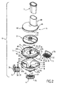
- a food cutting accessory according to the invention as illustrated figure 1 and designated as a whole by the reference A, is intended to be removably fitted on a motorized drive housing B.
- the plate 1 comprises a bottom 10 which forms a receiving seat 11 for the primary cutting tool 2 and which is surrounded by a peripheral rim 12.
- the plate 1 thus partially delimits a working chamber 13.
- the working chamber 13 advantageously has a substantially cylindrical general shape of revolution along an axis of rotation ⁇ .
- the primary cutting tool 2 is rotatable in the working chamber 13 along the axis of rotation ⁇ substantially perpendicular to the bottom 10.
- the bottom 10 is provided with a window of section 14 for receiving one or other of the three secondary cutting tools 3, 4, 5.
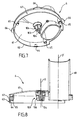
- the plate 1 comprises a cut food outlet conduit 15 which is connected to the cutting window 14 and which extends outside the working chamber 13.
- the conduit 15 has one end. substantially straight which extends along a longitudinal axis D forming, with the axis of ⁇ rotation, an acute angle ⁇ between 20 ° and 50 °, visible at the figure 3 , so as to facilitate the establishment of a container R under the free end 16 of the duct 15.
- the duct 15 has a free end 16 distant by a length l greater than or equal to 100 mm from of the cutting window 14.
- the duct 15 has a section whose average maximum and minimum dimensions is at most equal to 65.5 mm, and / or whose maximum dimension is at most equal to 76 mm.
- the duct 15 has a decreasing section from the cutting window 14 to its free end 16.
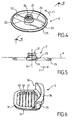
- the primary cutting tool 2 shown alone to Figures 4 and 5 , comprises a drive hub 21 from which extend two blades 22 which each comprise a main cutting edge 23 located in a cutting plane P substantially perpendicular to the axis of rotation ⁇ .
- Each blade 22 further comprises a pressure wedge 24 which is derived from the main cutting edge 23 and inclined in a direction opposite to the direction of rotation of the primary cutting tool 2 as indicated by the arrow F1.
- the primary cutting tool 2 also comprises a peripheral ring 25 which is intended to bear against the receiving seat 11 formed by the outer peripheral edge of the bottom 10.
- the drive hub 21 further comprises a drive window 26 whose function will appear later.
- Each secondary cutting tool 3, 4, 5 comprises a frame 31 which has an external shape complementary to that of the periphery of the cutting window 14.
- the frame 31 here has a generally rectangular shape with rounded corners and comprises three lateral stops 32 each located on one side of the frame 31 and intended to bear in three recesses 33 arranged at the periphery of the cutting window 14.
- the frame 31 further comprises a gripping member 34 L whose first branch 35 is s' extends vertically from one side of the frame 31 so as to follow the peripheral flange 12.
- the first branch 35 then has a shape complementary to that of the peripheral flange 12.
- the first branch 35 is extended by a second branch 36 which extends laterally from the first branch 35 towards the outside of the plate 1 so as to bear in a notch 37 located in the peripheral edge.
- the gripping member 34 which extends partly laterally outside the working chamber 13, makes it easy to remove the corresponding secondary cutting tool outside the cutting window 14 by a translation movement substantially parallel to the axis of rotation ⁇ of the primary cutting tool 2.
- the secondary cutting tools 3, 4, 5 are interchangeable.
- the first secondary cutting tool 3 comprises a first series of cutting members 40 substantially parallel to each other.
- Each cutting member 40 of the first series extends along an axis substantially parallel to the axis of rotation ⁇ and has a cutting edge 41 facing upwards.
- the first secondary cutting tool 3 makes it possible, when used with the primary cutting tool 2, to cut foodsticks into sticks.
- the second and third secondary cutting tools 4 and 5 each further comprise a second series of cutting members 45 substantially parallel to each other which define with the first series of cutting members 40 a grid of cutting.
- the second and third secondary cutting tools 4 and 5 allow cutting in cubes when used with the primary cutting tool 2.
- the lid 6, shown alone to Figures 7 and 8 is intended to be removably fitted on the plate 1 to partially close at least the working chamber 13.
- the cover 6 comprises a roof 61 which is bordered on its lower face by a peripheral skirt 62 which has an outer face 63 substantially cylindrical in revolution along the axis of rotation ⁇ and of complementary shape to that of the peripheral flange 12.
- the peripheral skirt 62 is intended to come to s inserting, at its lower part, between the peripheral ring 25 and the peripheral flange 12 so as to center the primary cutting tool 2.
- the peripheral skirt 62 has a lower face 64 also substantially cylindrical of revolution according to the axis of rotation ⁇ .
- the cover 6 also comprises three pins 65 intended to bear on the top of the peripheral ring 25.
- the cover 6 is movable on or in the plate 1 between an unlocked position in which it can be removed from the plate 1 in a translation movement parallel to the axis of rotation ⁇ and a locked position more particularly illustrated in FIG. figure 3 in which it can not be detached from the plate 1.
- a bayonet locking system which comprises four tabs 66 carried by the outer face 63 of the peripheral skirt 62 and intended to engage in four introduction windows 67a of the plate 1.
- the lid 6 further comprises a chute 68 for introducing food to be cut.
- the chute 68 extends in a longitudinal direction D 'substantially parallel to the axis of rotation ⁇ so as to be opposite the cutting window 14 when the lid 6 is in the locked position as shown in FIG. figure 3 . It should be noted that in the present case the lower end of the chute 68 extends below the roof 61 so as to guide the food to be cut closer to the cutting window 14 while leaving a passage for the blades 22 of the primary cutting tool 2.
- the casing 8 is located under the plate 1.
- the casing 8 is intended to come to fit under the plate 1 so as to improve the aesthetics of the latter.
- the casing 8 carries the plate 1.
- the casing 8 comprises a shell 81 which has a general funnel shape whose upper part, of generally cylindrical shape, defines a chamber 83 for receiving the plate 1.
- the shell 81 comprises a trunk 84 of cylindrical general shape of revolution which is connected to an upper portion 82 by an intermediate portion 85 of frustoconical general shape.
- the intermediate portion 85 comprises a window 86 for the passage of the duct 15.
- the duct 15 extends outside the casing 8.
- the casing 8 defines with the plate 1 storage slots 87 for the secondary cutting tools 3, 4, 5 outside the working chamber 13.
- the storage slots 87 are formed on the side of the plate 1 opposite the receiving seat 11 of the primary cutting tool 2.
- the housing 8 also comprises in its intermediate portion 85 two lateral openings 87a, 87b for the introduction of one of the cutting tools secondary 3, 4, 5 in one of the storage slots 87.
- the gripping member 34 of the secondary cutting tools 3, 4, 5 arranged in the storage slots 87 extends outside the lateral opening 87a, 87b .
- the trunk 84 carries, opposite the chamber 83, a base 88 of adaptation on the motorized drive box B which comprises for this purpose an adaptation housing 89 in which the base 88 is immobilized by a system bayonet lock 90.
- the housing 8 also comprises locking means 91 which cooperate with the cover 6 when the latter is in the locked position.
- the locking means 91 are of the bayonet type and comprise, in the present case, four locking tabs 92 under which the tabs 66 of the cover 6 are to be placed in the locked position thereof. latest.
- the plate 1 is perfectly immobilized between the lid 6 and the casing 8.
- the lid 6 in the locked position engages the casing 8.
- the lid 6 is locked by bayonet with the casing 8.
- the tabs 66 from the cover 6 are engaged under the locking tabs 92 coming from the housing 8 when the cover 6 is locked with the housing 8.
- the tabs 66 from the cover 6 are external.
- the locking tabs 92 from the housing 8 are internal.
- the plate 1 has an upper edge 69.
- the introduction windows 67a are formed in the upper edge 69 for the passage of the tabs 66 of the lid 6.
- the locking windows 67b extend the introduction windows 67a.
- the upper edge 69 extends above the locking tabs 92 when the plate 1 is in place on the housing.
- the tabs 66 are engaged in the locking windows 67b when the cover 6 is locked with the housing 8.
- the locking tabs 92 are disposed behind the locking windows 67b when the cover 6 is locked with the housing 8.
- the plate 1 has stops 99 arranged under the bottom 10. The stops cooperate for example with the cutting members 40, 45 and / or the frame 31.
- the food cutting accessory A also comprises drive means 100 of the primary cutting tool 2 rotating in the working chamber 13.
- the drive means 100 comprise a drive shaft 101 according to the axis of rotation ⁇ which is integral with the plate 1 being connected in translation to the latter and free to rotate along the axis of rotation. rotation ⁇ with respect thereto.
- the drive shaft 101 has a drive head 102 which extends into the working chamber 13.
- the drive head 102 has in cross section a larger dimension E which is strictly smaller than the smaller one dimension d of the drive window 26 of the drive hub 21.
- the drive shaft 101 can not directly drive the primary cutting tool 2.
- the drive head 102 has a fluted shape .
- the drive means 100 further comprise a drive bushing 103 which is carried by the cover 6 being connected in translation to the latter and free in rotation along the axis of rotation ⁇ relative thereto.
- the drive sleeve 103 is adapted to rotate the drive head 102 and the primary cutting tool 2 when the cover 6 is placed on or in the plate 1.
- the drive sleeve 103 comprises an axial drive bore 104 which has a shape complementary to that of the drive head 102.
- the drive sleeve 103 has an outer shape 106 complementary to that of the drive window 26.
- the drive window 26 has a fluted shape that converges towards the bottom 10 of the plate 1.
- the drive means 100 furthermore comprise an intermediate shaft 110 of axis of rotation ⁇ which is integral with the casing 8 while being connected in translation to the latter and free in rotation along the axis of rotation ⁇ with respect thereto.
- the intermediate shaft 110 comprises a drive foot 111 which extends outside the base 88 and which is intended to cooperate with an output shaft 112 of the motorized drive unit B, as shown in FIG. figure 1 .
- the intermediate shaft 110 comprises, opposite the drive foot 111, a coupling head 113 which is located inside the housing 8 and which is intended to cooperate with a coupling foot 114 carried by the drive shaft 101.
- the housing 8 carries the base 88 and comprises the intermediate shaft 110 rotatably connected to the drive shaft 101 and adapted to transmit the rotational movement of the output shaft 112 to the drive shaft 101 .
- the implementation of the coupling foot 114 and the coupling head 113 prevents the primary cutting tool 2 can be driven while the housing 8 and the plate 1 are not assembled.
- the plate 1 is engaged in the casing 8, the duct 15 being engaged in the window 86 and the coupling foot 114 coming to engage in translation along the axis of rotation ⁇ on the coupling head 113.
- the driving head 102 and the driving foot 111 are connected in rotation.
- the subset thus formed can be placed on the motorized drive housing B, the drive foot 111 coming into engagement with the output shaft 112 while the base 88 is locked in the adaptation housing 89 of said motorized drive housing B.
- one of the secondary cutting tools 3, 4, 5 is disposed in the cutting window 14 in a translation movement substantially parallel to the axis of rotation ⁇ while the other two secondary cutting tools are each placed in one of the storage slots 87.
- the primary cutting tool 2 can then be placed in the working chamber 13, the drive window 26 being centered on the driving head 102.
- the mounting of the feed cutting accessory A is completed by placing the cover 6 on the plate 1, the peripheral skirt 62 coming between the peripheral ring 25 and the peripheral flange 12 while the drive sleeve 103 engages in the drive window 26 and on the drive head 102
- the locking of the cover 6 is ensured by a rotational movement along the axis of rotation ⁇ so as to place the tabs 66 under the locking tabs 92.
- the food cutting accessory A can then be used to cut food.
- the motorized drive unit B comprises a vertical output shaft 112.
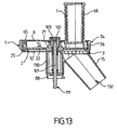
- the food cutting accessory A can also be used with a motorized drive box B ', as illustrated. figure 12 whose output shaft 112 is horizontal.
- the food cutting accessory A may be associated with a removable adapter C comprising means 121 for receiving the base 88 and an adapter foot 122 on the motorized drive box B '.
- the adapter C comprises an angular return block 120 comprising at least a gear train 123 providing a bevel gear between a transmission foot 124 which cooperates with the output shaft 112 and a transmission head 125 which cooperates with the drive foot 111, the transmission foot 124 having a rotation movement on itself coaxial with that of the drive shaft 101 and the transmission head 125 having a rotational movement on itself coaxial with that of the drive foot 111.
- the gear train 123 comprises for example two bevel gears, one 127 rotatably connected to the transmission base 124 and the other 128 to the transmission head 125.
- the housing 8 carries the base 88 and comprises the intermediate shaft 110 rotatably connected to the drive shaft 101 and adapted to transmit the rotational movement of the transmission head 125 to the drive shaft 101.
- the adapter C does not necessarily include an angular return block 120.
- the adapter C may include in particular an adapter foot 122 whose configuration is different from the configuration of the base 88 of the food cutting accessory A, to allow mounting of the food cutting accessory A on other types of motorized housings.
- the food cutting accessory A may comprise at least one secondary cutting tool 3, 4, 5 fixed. If desired the food cutting accessory A may have a plurality of interchangeable fixed secondary cutting tools.
- the locking means 91 are not necessarily of the bayonet type.
- the cover 6 may in particular be assembled with the housing 8 by screwing, by at least one flange or by at least one hook.
- the lid 6 is not necessarily removable relative to the plate 1 and to the casing 8.
- the lid 6 may in particular be pivotally mounted on the plate 1 or on the casing 8.
- the plate 1 is not necessarily locked with the lid 6 when the casing 8 is locked with the lid 6.
- the casing 8 does not necessarily comprise locking means 91 cooperating with the cover 6.
- the casing 8 can in particular comprise locking means cooperating with the plate 1, the plate 1 comprising other locking means cooperating with each other. with the lid 6.
- the cover 6 may for example be locked with the plate 1 by means of the tabs 66 engaged in the locking windows 67b.
- the food cutting accessory A comprises a housing 8.
- the implementation of such a housing 8 is not necessary for the realization of a food cutting accessory A according to the invention .
- the figure 13 illustrates another embodiment in which it is not implemented crankcase.
- the plate 1 then comprises a trunk 130 which carries the base 88.
- the cover 6 is locked on the plate 1.
- the drive shaft 101 integrates both the drive head 102 and the drive foot 111 and extends from below the base 88 to the inside of the working chamber 13.
- the duct 15 comprises, near its free end 16, at least one stop bar 132 extending across its passage section.
- the stop bar 132 thus prevents the passage of a hand through the conduit 15.
Claims (15)
- Zubehör (A) zum Zerkleinern von Lebensmitteln mit:- einer Platte (1), die einen Boden (10) umfasst, der mit einem Sitz (11) zur Aufnahme eines primären Schneidwerkzeugs (2), das um eine Drehachse (Δ) drehbar ist, sowie mit einem Schneidfenster (14) versehen ist, wobei die Platte (1) einen Teil eines Arbeitsraums (13) begrenzt, der dem Boden (10) gegenüberliegend offen ist,- einem Deckel (6), der so ausgelegt ist, dass er zumindest teilweise den Arbeitsraum (13) verschließt, wobei der Deckel (6) einen Schacht (68) zum Einfüllen der zu zerkleinernden Lebensmittel umfasst, der sich im Wesentlichen gegenüber dem Schneidfenster (14) befindet,- Mitteln (100) für den Drehantrieb des primären Schneidwerkzeugs (2),dadurch gekennzeichnet, dass:- das primäre Schneidwerkzeug (2) eine Antriebsnabe (21) mit einem Antriebsfenster (26) umfasst, das im Querschnitt ein kleineres Maß (d) aufweist,- wobei die Antriebsmittel (100) Folgendes umfassen:- eine Antriebswelle (101) mit der Drehachse (Δ), die fest mit der Platte (1) verbunden ist, die einen Antriebskopf (102) aufweist, der sich in den Arbeitsraum (13) erstreckt und im Querschnitt ein größeres Maß (E) aufweist, das in jedem Fall kleiner als das kleinere Maß (d) des Antriebsfensters (26) ist,- eine Antriebshülse (103), die um die Drehachse (Δ) frei drehbar zum Deckel (6) und axial verschiebbar mit dem Deckel (6) verbunden ist, der eine verformte axiale Antriebsbohrung (104) aufweist, die diejenige des Antriebskopfes (102) ergänzt und so ausgelegt ist, dass sie bei axialer Verschiebung an dem genannten Antriebskopf (102) einrastet, und eine äußere Form (106) aufweist, die diejenige des Antriebsfensters (26) ergänzt, und so ausgelegt ist, dass sie bei axialer Verschiebung in das genannte Antriebsfenster (26) einrastet.
- Zubehör (A) zum Zerkleinern von Lebensmitteln nach Anspruch 1, dadurch gekennzeichnet, dass sich die Innenseite des Antriebsfensters (26) zur Platte (1) hin verjüngt.
- Zubehör (A) zum Zerkleinern von Lebensmitteln nach Anspruch 1 oder 2, dadurch gekennzeichnet, dass der Antriebskopf (102) eine geriffelte Form aufweist.
- Zubehör (A) zum Zerkleinern von Lebensmitteln nach einem der Ansprüche 1 bis 3, dadurch gekennzeichnet, dass das Antriebsfenster (26) eine geriffelte Form aufweist.
- Zubehör (A) zum Zerkleinern von Lebensmitteln nach einem der Ansprüche 1 bis 4, dadurch gekennzeichnet, dass die Platte (1) einen Kanal (15) zum Ausgeben der zerkleinerten Lebensmittel umfasst, der mit dem Schneidfenster (14) verbunden ist und außerhalb des Arbeitsraums (13) und gegenüber dem Schacht (68) verläuft.
- Zubehör (A) zum Zerkleinern von Lebensmitteln nach Anspruch 5, dadurch gekennzeichnet, dass der Kanal (15) entlang einer Längsachse (D) verläuft, die einen spitzen Winkel (a) ungleich Null mit der Drehachse (Δ) bildet.
- Zubehör (A) zum Zerkleinern von Lebensmitteln nach einem der Ansprüche 5 oder 6, dadurch gekennzeichnet, dass der Kanal (15) ein freies Ende (16) aufweist, dass eine Länge (I) von mindestens 100 mm von dem Schneidfenster (14) entfernt ist.
- Zubehör (A) zum Zerkleinern von Lebensmitteln nach einem der Ansprüche 5 bis 7, dadurch gekennzeichnet, dass der Kanal (15) einen Querschnitt aufweist, dessen Mittelwert aus der maximalen Abmessung und der minimalen Abmessung höchstens 65,5 mm beträgt und/oder dessen maximale Abmessung höchstens 76 mm beträgt.
- Zubehör (A) zum Zerkleinern von Lebensmitteln nach einem der Ansprüche 1 bis 8, dadurch gekennzeichnet, dass sich der Schacht (68) in einer im Wesentlichen zur Drehachse (Δ) parallelen Längsrichtung (D') erstreckt.
- Zubehör (A) zum Zerkleinern von Lebensmitteln nach einem der Ansprüche 1 bis 9, dadurch gekennzeichnet, dass es ein feststehendes sekundäres Schneidwerkzeug (3; 4; 5) umfasst, das abnehmbar in dem Schneidfenster (14) sitzt.
- Zubehör (A) zum Zerkleinern von Lebensmitteln nach einem der Ansprüche 1 bis 10, dadurch gekennzeichnet, dass es einen Sockel (88) zum Anschluss an ein Motorantriebsgehäuse (B) und/oder an einen Adapter (C) umfasst, wobei die Antriebsmittel (100) so ausgelegt sind, dass sie die Übertragung der Drehbewegung von einer Abtriebswelle (112) des Motorantriebsgehäuses (B) oder einem Getriebekopf (125) des Adapters (C) auf die Antriebswelle (101) sicherstellen.
- Zubehör (A) zum Zerkleinern von Lebensmitteln nach Anspruch 11, dadurch gekennzeichnet, dass es eine Schale (8) umfasst, die den Sockel (88) trägt und eine Zwischenwelle (110) umfasst, die mit der Antriebswelle (101) drehfest verbunden und so ausgelegt ist, dass sie die Drehbewegung der Abtriebswelle (112) oder des Getriebekopfes (125) auf die Antriebswelle (101) überträgt.
- Einheit zum Zerkleinern von Lebensmitteln mit einem Zubehör (A) zum Zerkleinern von Lebensmitteln nach einem der Ansprüche 11 oder 12 und einem abnehmbaren Adapter (C) mit Mitteln (121) zur Aufnahme des Sockels (88), einem Adapterfuß (122) an dem Motorantriebsgehäuse (B') und einem Getriebefuß (124), der so ausgelegt ist, dass er mit der Abtriebswelle (112) des Motorantriebsgehäuses (B') zusammenwirkt, wobei der Getriebekopf (125) von dem Getriebefuß (124) angetrieben wird und wobei der Getriebekopf (125) so ausgelegt ist, dass er mit dem Antriebsfuß (111) des Sockels (88) zusammenwirkt.
- Einheit zum Zerkleinern von Lebensmitteln nach Anspruch 13, dadurch gekennzeichnet, dass der Adapter (C) ein Winkelgetriebe (120) mit zumindest einer Verzahnung (123) umfasst, die die Eckumlenkung zwischen dem Getriebekopf (125) und dem Getriebefuß (124) sicherstellt.
- Elektrohaushaltsgerät zur Zubereitung von Speisen mit einem Motorantriebsgehäuse (B, B'), falls gewünscht einem abnehmbaren Adapter (C), der auf das Motorantriebsgehäuse (B') montiert wird, und einem abnehmbaren Zubehör (A) zum Zerkleinern von Lebensmitteln, das auf das Motorantriebsgehäuse (B) und/oder den Adapter (C) montiert wird, dadurch gekennzeichnet, dass das Zubehör (A) zum Zerkleinern von Lebensmitteln einem der Ansprüche 1 bis 12 entspricht.
Applications Claiming Priority (1)
| Application Number | Priority Date | Filing Date | Title |
|---|---|---|---|
| FR1359128A FR3010887B1 (fr) | 2013-09-23 | 2013-09-23 | Accessoire pour decouper des aliments comprenant des moyens securises d’entrainement en rotation d’un outil de coupe |
Publications (2)
| Publication Number | Publication Date |
|---|---|
| EP2859823A1 EP2859823A1 (de) | 2015-04-15 |
| EP2859823B1 true EP2859823B1 (de) | 2016-09-07 |
Family
ID=49551671
Family Applications (1)
| Application Number | Title | Priority Date | Filing Date |
|---|---|---|---|
| EP14185979.3A Active EP2859823B1 (de) | 2013-09-23 | 2014-09-23 | Zubehör zum Schneiden von Lebensmitteln, das gesicherte Drehantriebsmittel eines Schneidwerkzeugs umfasst |
Country Status (5)
| Country | Link |
|---|---|
| EP (1) | EP2859823B1 (de) |
| CN (2) | CN204322137U (de) |
| FR (1) | FR3010887B1 (de) |
| PL (1) | PL2859823T3 (de) |
| WO (1) | WO2015040345A1 (de) |
Families Citing this family (3)
| Publication number | Priority date | Publication date | Assignee | Title |
|---|---|---|---|---|
| FR3010887B1 (fr) * | 2013-09-23 | 2015-09-04 | Seb Sa | Accessoire pour decouper des aliments comprenant des moyens securises d’entrainement en rotation d’un outil de coupe |
| GB2547895B (en) * | 2016-02-25 | 2022-04-06 | Kenwood Ltd | Kitchen appliance, food processor and safety interlock arrangement |
| WO2017205471A1 (en) | 2016-05-25 | 2017-11-30 | Sharkninja Operating Llc | Oscillating blade for food processor system |
Family Cites Families (7)
| Publication number | Priority date | Publication date | Assignee | Title |
|---|---|---|---|---|
| CN2543677Y (zh) * | 2002-07-01 | 2003-04-09 | 宋老亮 | 蔬菜加工机 |
| SE520337C2 (sv) * | 2002-09-17 | 2003-06-24 | Haellde Maskiner Ab | Anordning för matberedning |
| FR2926969B1 (fr) * | 2008-01-31 | 2012-11-02 | Seb Sa | Appareil electromenager de preparation culinaire comprenant un boitier renfermant un moteur et un recipient recevant un outil rotatif |
| DE102008040937A1 (de) * | 2008-08-01 | 2010-02-11 | BSH Bosch und Siemens Hausgeräte GmbH | Vorrichtung zum Zerteilen von Bearbeitungsgut, insbesondere zum Würfeln von Lebensmitteln, und Küchenmaschine |
| US8122820B2 (en) * | 2008-12-19 | 2012-02-28 | Whirlpool Corporation | Food processor with dicing tool |
| EP2564745A1 (de) | 2011-09-01 | 2013-03-06 | Koninklijke Philips Electronics N.V. | Deckel für einen Lebensmittelprozessor |
| FR3010887B1 (fr) * | 2013-09-23 | 2015-09-04 | Seb Sa | Accessoire pour decouper des aliments comprenant des moyens securises d’entrainement en rotation d’un outil de coupe |
-
2013
- 2013-09-23 FR FR1359128A patent/FR3010887B1/fr not_active Expired - Fee Related
-
2014
- 2014-09-19 CN CN201420541726.1U patent/CN204322137U/zh not_active Withdrawn - After Issue
- 2014-09-19 CN CN201410482722.5A patent/CN104441003B/zh active Active
- 2014-09-23 PL PL14185979T patent/PL2859823T3/pl unknown
- 2014-09-23 WO PCT/FR2014/052363 patent/WO2015040345A1/fr active Application Filing
- 2014-09-23 EP EP14185979.3A patent/EP2859823B1/de active Active
Also Published As
| Publication number | Publication date |
|---|---|
| FR3010887B1 (fr) | 2015-09-04 |
| CN204322137U (zh) | 2015-05-13 |
| EP2859823A1 (de) | 2015-04-15 |
| WO2015040345A1 (fr) | 2015-03-26 |
| CN104441003B (zh) | 2018-03-20 |
| PL2859823T3 (pl) | 2017-02-28 |
| CN104441003A (zh) | 2015-03-25 |
| FR3010887A1 (fr) | 2015-03-27 |
Similar Documents
| Publication | Publication Date | Title |
|---|---|---|
| EP2856919B1 (de) | Zubehör zum Schneiden von Lebensmitteln, das mehrere Werkzeuge für den Nachschnitt umfasst | |
| EP2515721B1 (de) | Elektrisches küchengerät mit druckschraube und vorschneidelement | |
| CA2837644C (fr) | Outil de coupe d'aliments en morceaux | |
| FR2967034A1 (fr) | Appareil electromenager de preparation culinaire comportant une vis de pressage | |
| EP2846664B1 (de) | Rotierendes arbeitselement und elektrisches haushaltsgerät für die zubereitung von lebensmitteln mit einer pressschraube | |
| EP2853184B1 (de) | Zubehör zum Schneiden von Lebensmitteln, dessen stationäres sekundäres Schneidwerkzeug Greifmittel umfasst | |
| FR2935285A1 (fr) | Appareil electromenager de decoupe d'aliments en continu avec montage d'outil simplifie | |
| EP2859823B1 (de) | Zubehör zum Schneiden von Lebensmitteln, das gesicherte Drehantriebsmittel eines Schneidwerkzeugs umfasst | |
| EP2859824B1 (de) | Zubehörteil zum Schneiden von Lebensmitteln in Stücke | |
| EP3188631B1 (de) | Lebensmittelzubereitungsvorrichtung zum arbeiten mit gekochten oder frittierbaren nahrungsmitteln | |
| FR3051651A1 (fr) | Outil de petrissage pour appareil electromenager de preparation culinaire | |
| EP3082533A2 (de) | Vorrichtung zur fragmentierung von nahrung und zum von fragmentierter nahrung | |
| EP2682032B1 (de) | Elektrohaushaltsgerät zum Schneiden von Lebensmitteln mit Ablage für die Zubehörteile zum Schneiden der Lebensmittel | |
| EP3169208B1 (de) | Umkehrbares rotierendes verarbeitungswerkzeug sowie lebensmittelzubereitungsvorrichtung mit umkehrbarem rotierenden verarbeitungswerkzeug | |
| FR2955475A1 (fr) | Appareil multifonctionnel de traitement mecanique d'aliments comportant une fonction centrifugeuse et une fonction coupe-legumes | |
| EP2949247B1 (de) | Vorrichtung zur lebensmittelzubereitung, die an die extraktion von saft und/oder püree angepasst ist | |
| FR3018180A1 (fr) | Dispositif de preparation d’aliments comportant une cheminee d’alimentation recevant un poussoir anti debordement |
Legal Events
| Date | Code | Title | Description |
|---|---|---|---|
| PUAI | Public reference made under article 153(3) epc to a published international application that has entered the european phase |
Free format text: ORIGINAL CODE: 0009012 |
|
| 17P | Request for examination filed |
Effective date: 20140923 |
|
| AK | Designated contracting states |
Kind code of ref document: A1 Designated state(s): AL AT BE BG CH CY CZ DE DK EE ES FI FR GB GR HR HU IE IS IT LI LT LU LV MC MK MT NL NO PL PT RO RS SE SI SK SM TR |
|
| AX | Request for extension of the european patent |
Extension state: BA ME |
|
| R17P | Request for examination filed (corrected) |
Effective date: 20151007 |
|
| RBV | Designated contracting states (corrected) |
Designated state(s): AL AT BE BG CH CY CZ DE DK EE ES FI FR GB GR HR HU IE IS IT LI LT LU LV MC MK MT NL NO PL PT RO RS SE SI SK SM TR |
|
| GRAP | Despatch of communication of intention to grant a patent |
Free format text: ORIGINAL CODE: EPIDOSNIGR1 |
|
| RIC1 | Information provided on ipc code assigned before grant |
Ipc: B26D 3/18 20060101ALI20160302BHEP Ipc: B26D 1/03 20060101ALI20160302BHEP Ipc: A47J 43/07 20060101ALI20160302BHEP Ipc: B26D 1/29 20060101ALI20160302BHEP Ipc: B26D 1/553 20060101ALI20160302BHEP Ipc: B26D 7/06 20060101ALI20160302BHEP Ipc: A47J 43/08 20060101ALI20160302BHEP Ipc: B26D 11/00 20060101ALI20160302BHEP Ipc: A47J 43/046 20060101AFI20160302BHEP |
|
| INTG | Intention to grant announced |
Effective date: 20160324 |
|
| GRAS | Grant fee paid |
Free format text: ORIGINAL CODE: EPIDOSNIGR3 |
|
| GRAA | (expected) grant |
Free format text: ORIGINAL CODE: 0009210 |
|
| AK | Designated contracting states |
Kind code of ref document: B1 Designated state(s): AL AT BE BG CH CY CZ DE DK EE ES FI FR GB GR HR HU IE IS IT LI LT LU LV MC MK MT NL NO PL PT RO RS SE SI SK SM TR |
|
| REG | Reference to a national code |
Ref country code: GB Ref legal event code: FG4D Free format text: NOT ENGLISH |
|
| REG | Reference to a national code |
Ref country code: CH Ref legal event code: EP |
|
| REG | Reference to a national code |
Ref country code: FR Ref legal event code: PLFP Year of fee payment: 3 |
|
| REG | Reference to a national code |
Ref country code: IE Ref legal event code: FG4D Free format text: LANGUAGE OF EP DOCUMENT: FRENCH |
|
| RAP2 | Party data changed (patent owner data changed or rights of a patent transferred) |
Owner name: SEB S.A. |
|
| REG | Reference to a national code |
Ref country code: CH Ref legal event code: PCOW Free format text: NEW ADDRESS: 112 CHEMIN DU MOULIN CARRON CAMPUS SEB, 69130 ECULLY (FR) |
|
| REG | Reference to a national code |
Ref country code: AT Ref legal event code: REF Ref document number: 826049 Country of ref document: AT Kind code of ref document: T Effective date: 20161015 |
|
| REG | Reference to a national code |
Ref country code: DE Ref legal event code: R096 Ref document number: 602014003492 Country of ref document: DE |
|
| REG | Reference to a national code |
Ref country code: LT Ref legal event code: MG4D |
|
| REG | Reference to a national code |
Ref country code: NL Ref legal event code: MP Effective date: 20160907 |
|
| PG25 | Lapsed in a contracting state [announced via postgrant information from national office to epo] |
Ref country code: FI Free format text: LAPSE BECAUSE OF FAILURE TO SUBMIT A TRANSLATION OF THE DESCRIPTION OR TO PAY THE FEE WITHIN THE PRESCRIBED TIME-LIMIT Effective date: 20160907 Ref country code: RS Free format text: LAPSE BECAUSE OF FAILURE TO SUBMIT A TRANSLATION OF THE DESCRIPTION OR TO PAY THE FEE WITHIN THE PRESCRIBED TIME-LIMIT Effective date: 20160907 Ref country code: NO Free format text: LAPSE BECAUSE OF FAILURE TO SUBMIT A TRANSLATION OF THE DESCRIPTION OR TO PAY THE FEE WITHIN THE PRESCRIBED TIME-LIMIT Effective date: 20161207 Ref country code: HR Free format text: LAPSE BECAUSE OF FAILURE TO SUBMIT A TRANSLATION OF THE DESCRIPTION OR TO PAY THE FEE WITHIN THE PRESCRIBED TIME-LIMIT Effective date: 20160907 Ref country code: LT Free format text: LAPSE BECAUSE OF FAILURE TO SUBMIT A TRANSLATION OF THE DESCRIPTION OR TO PAY THE FEE WITHIN THE PRESCRIBED TIME-LIMIT Effective date: 20160907 |
|
| REG | Reference to a national code |
Ref country code: AT Ref legal event code: MK05 Ref document number: 826049 Country of ref document: AT Kind code of ref document: T Effective date: 20160907 |
|
| PG25 | Lapsed in a contracting state [announced via postgrant information from national office to epo] |
Ref country code: LV Free format text: LAPSE BECAUSE OF FAILURE TO SUBMIT A TRANSLATION OF THE DESCRIPTION OR TO PAY THE FEE WITHIN THE PRESCRIBED TIME-LIMIT Effective date: 20160907 Ref country code: ES Free format text: LAPSE BECAUSE OF FAILURE TO SUBMIT A TRANSLATION OF THE DESCRIPTION OR TO PAY THE FEE WITHIN THE PRESCRIBED TIME-LIMIT Effective date: 20160907 Ref country code: NL Free format text: LAPSE BECAUSE OF FAILURE TO SUBMIT A TRANSLATION OF THE DESCRIPTION OR TO PAY THE FEE WITHIN THE PRESCRIBED TIME-LIMIT Effective date: 20160907 Ref country code: GR Free format text: LAPSE BECAUSE OF FAILURE TO SUBMIT A TRANSLATION OF THE DESCRIPTION OR TO PAY THE FEE WITHIN THE PRESCRIBED TIME-LIMIT Effective date: 20161208 Ref country code: BE Free format text: LAPSE BECAUSE OF NON-PAYMENT OF DUE FEES Effective date: 20160930 Ref country code: SE Free format text: LAPSE BECAUSE OF FAILURE TO SUBMIT A TRANSLATION OF THE DESCRIPTION OR TO PAY THE FEE WITHIN THE PRESCRIBED TIME-LIMIT Effective date: 20160907 |
|
| PG25 | Lapsed in a contracting state [announced via postgrant information from national office to epo] |
Ref country code: EE Free format text: LAPSE BECAUSE OF FAILURE TO SUBMIT A TRANSLATION OF THE DESCRIPTION OR TO PAY THE FEE WITHIN THE PRESCRIBED TIME-LIMIT Effective date: 20160907 Ref country code: RO Free format text: LAPSE BECAUSE OF FAILURE TO SUBMIT A TRANSLATION OF THE DESCRIPTION OR TO PAY THE FEE WITHIN THE PRESCRIBED TIME-LIMIT Effective date: 20160907 |
|
| PG25 | Lapsed in a contracting state [announced via postgrant information from national office to epo] |
Ref country code: SK Free format text: LAPSE BECAUSE OF FAILURE TO SUBMIT A TRANSLATION OF THE DESCRIPTION OR TO PAY THE FEE WITHIN THE PRESCRIBED TIME-LIMIT Effective date: 20160907 Ref country code: PT Free format text: LAPSE BECAUSE OF FAILURE TO SUBMIT A TRANSLATION OF THE DESCRIPTION OR TO PAY THE FEE WITHIN THE PRESCRIBED TIME-LIMIT Effective date: 20170109 Ref country code: IS Free format text: LAPSE BECAUSE OF FAILURE TO SUBMIT A TRANSLATION OF THE DESCRIPTION OR TO PAY THE FEE WITHIN THE PRESCRIBED TIME-LIMIT Effective date: 20170107 Ref country code: SM Free format text: LAPSE BECAUSE OF FAILURE TO SUBMIT A TRANSLATION OF THE DESCRIPTION OR TO PAY THE FEE WITHIN THE PRESCRIBED TIME-LIMIT Effective date: 20160907 Ref country code: AT Free format text: LAPSE BECAUSE OF FAILURE TO SUBMIT A TRANSLATION OF THE DESCRIPTION OR TO PAY THE FEE WITHIN THE PRESCRIBED TIME-LIMIT Effective date: 20160907 Ref country code: BG Free format text: LAPSE BECAUSE OF FAILURE TO SUBMIT A TRANSLATION OF THE DESCRIPTION OR TO PAY THE FEE WITHIN THE PRESCRIBED TIME-LIMIT Effective date: 20161207 Ref country code: CZ Free format text: LAPSE BECAUSE OF FAILURE TO SUBMIT A TRANSLATION OF THE DESCRIPTION OR TO PAY THE FEE WITHIN THE PRESCRIBED TIME-LIMIT Effective date: 20160907 |
|
| REG | Reference to a national code |
Ref country code: DE Ref legal event code: R097 Ref document number: 602014003492 Country of ref document: DE |
|
| REG | Reference to a national code |
Ref country code: FR Ref legal event code: CA Effective date: 20170518 |
|
| REG | Reference to a national code |
Ref country code: IE Ref legal event code: MM4A |
|
| PG25 | Lapsed in a contracting state [announced via postgrant information from national office to epo] |
Ref country code: IT Free format text: LAPSE BECAUSE OF FAILURE TO SUBMIT A TRANSLATION OF THE DESCRIPTION OR TO PAY THE FEE WITHIN THE PRESCRIBED TIME-LIMIT Effective date: 20160907 |
|
| PLBE | No opposition filed within time limit |
Free format text: ORIGINAL CODE: 0009261 |
|
| STAA | Information on the status of an ep patent application or granted ep patent |
Free format text: STATUS: NO OPPOSITION FILED WITHIN TIME LIMIT |
|
| PG25 | Lapsed in a contracting state [announced via postgrant information from national office to epo] |
Ref country code: IE Free format text: LAPSE BECAUSE OF NON-PAYMENT OF DUE FEES Effective date: 20160923 Ref country code: DK Free format text: LAPSE BECAUSE OF FAILURE TO SUBMIT A TRANSLATION OF THE DESCRIPTION OR TO PAY THE FEE WITHIN THE PRESCRIBED TIME-LIMIT Effective date: 20160907 |
|
| 26N | No opposition filed |
Effective date: 20170608 |
|
| PG25 | Lapsed in a contracting state [announced via postgrant information from national office to epo] |
Ref country code: SI Free format text: LAPSE BECAUSE OF FAILURE TO SUBMIT A TRANSLATION OF THE DESCRIPTION OR TO PAY THE FEE WITHIN THE PRESCRIBED TIME-LIMIT Effective date: 20160907 Ref country code: LU Free format text: LAPSE BECAUSE OF NON-PAYMENT OF DUE FEES Effective date: 20160923 |
|
| REG | Reference to a national code |
Ref country code: FR Ref legal event code: PLFP Year of fee payment: 4 |
|
| REG | Reference to a national code |
Ref country code: BE Ref legal event code: MM Effective date: 20160930 |
|
| REG | Reference to a national code |
Ref country code: CH Ref legal event code: PL |
|
| PG25 | Lapsed in a contracting state [announced via postgrant information from national office to epo] |
Ref country code: HU Free format text: LAPSE BECAUSE OF FAILURE TO SUBMIT A TRANSLATION OF THE DESCRIPTION OR TO PAY THE FEE WITHIN THE PRESCRIBED TIME-LIMIT; INVALID AB INITIO Effective date: 20140923 |
|
| PG25 | Lapsed in a contracting state [announced via postgrant information from national office to epo] |
Ref country code: MK Free format text: LAPSE BECAUSE OF FAILURE TO SUBMIT A TRANSLATION OF THE DESCRIPTION OR TO PAY THE FEE WITHIN THE PRESCRIBED TIME-LIMIT Effective date: 20160907 Ref country code: CY Free format text: LAPSE BECAUSE OF FAILURE TO SUBMIT A TRANSLATION OF THE DESCRIPTION OR TO PAY THE FEE WITHIN THE PRESCRIBED TIME-LIMIT Effective date: 20160907 Ref country code: MT Free format text: LAPSE BECAUSE OF FAILURE TO SUBMIT A TRANSLATION OF THE DESCRIPTION OR TO PAY THE FEE WITHIN THE PRESCRIBED TIME-LIMIT Effective date: 20160907 Ref country code: MC Free format text: LAPSE BECAUSE OF FAILURE TO SUBMIT A TRANSLATION OF THE DESCRIPTION OR TO PAY THE FEE WITHIN THE PRESCRIBED TIME-LIMIT Effective date: 20160907 |
|
| PG25 | Lapsed in a contracting state [announced via postgrant information from national office to epo] |
Ref country code: LI Free format text: LAPSE BECAUSE OF NON-PAYMENT OF DUE FEES Effective date: 20170930 Ref country code: CH Free format text: LAPSE BECAUSE OF NON-PAYMENT OF DUE FEES Effective date: 20170930 |
|
| REG | Reference to a national code |
Ref country code: FR Ref legal event code: PLFP Year of fee payment: 5 |
|
| PG25 | Lapsed in a contracting state [announced via postgrant information from national office to epo] |
Ref country code: AL Free format text: LAPSE BECAUSE OF FAILURE TO SUBMIT A TRANSLATION OF THE DESCRIPTION OR TO PAY THE FEE WITHIN THE PRESCRIBED TIME-LIMIT Effective date: 20160907 |
|
| PGFP | Annual fee paid to national office [announced via postgrant information from national office to epo] |
Ref country code: GB Payment date: 20210928 Year of fee payment: 8 |
|
| GBPC | Gb: european patent ceased through non-payment of renewal fee |
Effective date: 20220923 |
|
| PG25 | Lapsed in a contracting state [announced via postgrant information from national office to epo] |
Ref country code: GB Free format text: LAPSE BECAUSE OF NON-PAYMENT OF DUE FEES Effective date: 20220923 |
|
| PGFP | Annual fee paid to national office [announced via postgrant information from national office to epo] |
Ref country code: TR Payment date: 20230912 Year of fee payment: 10 |
|
| PGFP | Annual fee paid to national office [announced via postgrant information from national office to epo] |
Ref country code: PL Payment date: 20230830 Year of fee payment: 10 Ref country code: FR Payment date: 20230927 Year of fee payment: 10 Ref country code: DE Payment date: 20230911 Year of fee payment: 10 |