EP2859664B1 - Transmission d'un signal de référence sonore sur la liaison montante - Google Patents
Transmission d'un signal de référence sonore sur la liaison montante Download PDFInfo
- Publication number
- EP2859664B1 EP2859664B1 EP13804562.0A EP13804562A EP2859664B1 EP 2859664 B1 EP2859664 B1 EP 2859664B1 EP 13804562 A EP13804562 A EP 13804562A EP 2859664 B1 EP2859664 B1 EP 2859664B1
- Authority
- EP
- European Patent Office
- Prior art keywords
- srs
- transmission
- reception point
- reference signal
- uplink
- Prior art date
- Legal status (The legal status is an assumption and is not a legal conclusion. Google has not performed a legal analysis and makes no representation as to the accuracy of the status listed.)
- Active
Links
- 230000005540 biological transmission Effects 0.000 title claims description 632
- 230000000737 periodic effect Effects 0.000 claims description 125
- 238000000034 method Methods 0.000 claims description 94
- 108091006146 Channels Proteins 0.000 description 185
- 230000011664 signaling Effects 0.000 description 34
- 238000004891 communication Methods 0.000 description 26
- 125000004122 cyclic group Chemical group 0.000 description 16
- 238000001774 stimulated Raman spectroscopy Methods 0.000 description 15
- 108010076504 Protein Sorting Signals Proteins 0.000 description 11
- 230000014509 gene expression Effects 0.000 description 8
- 238000005259 measurement Methods 0.000 description 7
- 101000741965 Homo sapiens Inactive tyrosine-protein kinase PRAG1 Proteins 0.000 description 4
- 102100038659 Inactive tyrosine-protein kinase PRAG1 Human genes 0.000 description 4
- 230000004069 differentiation Effects 0.000 description 4
- 230000004044 response Effects 0.000 description 4
- 230000008054 signal transmission Effects 0.000 description 4
- 238000010586 diagram Methods 0.000 description 3
- 230000006872 improvement Effects 0.000 description 3
- 230000001960 triggered effect Effects 0.000 description 3
- 238000005516 engineering process Methods 0.000 description 2
- 230000007274 generation of a signal involved in cell-cell signaling Effects 0.000 description 2
- 230000004075 alteration Effects 0.000 description 1
- 239000000969 carrier Substances 0.000 description 1
- 230000008878 coupling Effects 0.000 description 1
- 238000010168 coupling process Methods 0.000 description 1
- 238000005859 coupling reaction Methods 0.000 description 1
- 230000001419 dependent effect Effects 0.000 description 1
- VJYFKVYYMZPMAB-UHFFFAOYSA-N ethoprophos Chemical compound CCCSP(=O)(OCC)SCCC VJYFKVYYMZPMAB-UHFFFAOYSA-N 0.000 description 1
- 230000007774 longterm Effects 0.000 description 1
- 238000013507 mapping Methods 0.000 description 1
- 238000010295 mobile communication Methods 0.000 description 1
- 238000012986 modification Methods 0.000 description 1
- 230000004048 modification Effects 0.000 description 1
- 230000003287 optical effect Effects 0.000 description 1
- 239000013307 optical fiber Substances 0.000 description 1
- 230000008569 process Effects 0.000 description 1
- 238000013468 resource allocation Methods 0.000 description 1
- 238000006467 substitution reaction Methods 0.000 description 1
- 230000001360 synchronised effect Effects 0.000 description 1
Images


Classifications
-
- H—ELECTRICITY
- H04—ELECTRIC COMMUNICATION TECHNIQUE
- H04L—TRANSMISSION OF DIGITAL INFORMATION, e.g. TELEGRAPHIC COMMUNICATION
- H04L5/00—Arrangements affording multiple use of the transmission path
- H04L5/003—Arrangements for allocating sub-channels of the transmission path
- H04L5/0048—Allocation of pilot signals, i.e. of signals known to the receiver
-
- H—ELECTRICITY
- H04—ELECTRIC COMMUNICATION TECHNIQUE
- H04L—TRANSMISSION OF DIGITAL INFORMATION, e.g. TELEGRAPHIC COMMUNICATION
- H04L27/00—Modulated-carrier systems
- H04L27/26—Systems using multi-frequency codes
- H04L27/2601—Multicarrier modulation systems
- H04L27/2602—Signal structure
- H04L27/261—Details of reference signals
- H04L27/2613—Structure of the reference signals
-
- H—ELECTRICITY
- H04—ELECTRIC COMMUNICATION TECHNIQUE
- H04B—TRANSMISSION
- H04B7/00—Radio transmission systems, i.e. using radiation field
- H04B7/02—Diversity systems; Multi-antenna system, i.e. transmission or reception using multiple antennas
- H04B7/022—Site diversity; Macro-diversity
- H04B7/024—Co-operative use of antennas of several sites, e.g. in co-ordinated multipoint or co-operative multiple-input multiple-output [MIMO] systems
-
- H—ELECTRICITY
- H04—ELECTRIC COMMUNICATION TECHNIQUE
- H04L—TRANSMISSION OF DIGITAL INFORMATION, e.g. TELEGRAPHIC COMMUNICATION
- H04L1/00—Arrangements for detecting or preventing errors in the information received
- H04L1/0001—Systems modifying transmission characteristics according to link quality, e.g. power backoff
- H04L1/0023—Systems modifying transmission characteristics according to link quality, e.g. power backoff characterised by the signalling
-
- H—ELECTRICITY
- H04—ELECTRIC COMMUNICATION TECHNIQUE
- H04L—TRANSMISSION OF DIGITAL INFORMATION, e.g. TELEGRAPHIC COMMUNICATION
- H04L5/00—Arrangements affording multiple use of the transmission path
- H04L5/003—Arrangements for allocating sub-channels of the transmission path
- H04L5/0032—Distributed allocation, i.e. involving a plurality of allocating devices, each making partial allocation
- H04L5/0035—Resource allocation in a cooperative multipoint environment
-
- H—ELECTRICITY
- H04—ELECTRIC COMMUNICATION TECHNIQUE
- H04L—TRANSMISSION OF DIGITAL INFORMATION, e.g. TELEGRAPHIC COMMUNICATION
- H04L5/00—Arrangements affording multiple use of the transmission path
- H04L5/003—Arrangements for allocating sub-channels of the transmission path
- H04L5/0053—Allocation of signaling, i.e. of overhead other than pilot signals
-
- H—ELECTRICITY
- H04—ELECTRIC COMMUNICATION TECHNIQUE
- H04W—WIRELESS COMMUNICATION NETWORKS
- H04W72/00—Local resource management
- H04W72/50—Allocation or scheduling criteria for wireless resources
- H04W72/51—Allocation or scheduling criteria for wireless resources based on terminal or device properties
-
- H—ELECTRICITY
- H04—ELECTRIC COMMUNICATION TECHNIQUE
- H04W—WIRELESS COMMUNICATION NETWORKS
- H04W72/00—Local resource management
- H04W72/12—Wireless traffic scheduling
Definitions
- the present invention relates to a physical uplink channel, and particularly, to transmission of uplink sounding reference signal.
- a coordinated multi-point transmission/reception system In a coordinated multi-point transmission/reception system (CoMP system), at least two of transmission and reception points cooperate with each other to transmit signals.
- CoMP system measures an uplink channel state for uplink frequency-dependent schedule and measures an uplink/downlink channel for downlink beam-forming using channel reciprocity.
- SRS sounding reference signal
- Examples of methods according to the prior art for the transmission of uplink sounding reference signals are known from " 3rd Generation Partnership Project; Technical Specification Group Radio Access Network; Coordinated multi-point operation for LTE physical layer aspects (Release 11)", 3GPP STANDARD; 3GPP TR 36.819, 3RD GENERATION PARTNERSHIP PROJECT (3GPP), MOBILE COMPETENCE CENTRE; 650, ROUTE DES LUCIOLES; F-06921 SOPHIA-ANTIPOLIS CEDEX; FRANCE, vol. RAN WG1, no. V11.0.0,27 September 2011 (2011-09-27), pages 1-68, (retrieved on 2011-09-27 ).
- a method for transmitting an uplink sounding reference signal (SRS) in user equipment (UE).
- the method includes receiving UE-specific configuration information indicating an uplink reference signal identity from a first transmission/reception point of a plurality of different transmission/reception points, wherein the uplink reference signal identity is independent of a physical cell identity of the first transmission/reception point and is associated with an uplink channel, wherein the uplink reference signal identity indicates a second transmission/reception point as a reception entity of the uplink channel; transmitting the uplink channel to the second transmission/reception point indicated by the uplink reference signal identity, using the uplink reference signal identity, wherein the second transmission/reception point is different from the first transmission/reception point; generating a sounding reference signal (SRS) independent of the uplink channel, using the physical cell identity of the first transmission/reception point; and transmitting the generated SRS to the first transmission/reception point.
- SRS sounding reference signal
- the SRS includes at least one of a periodic SRS and an aperiodic SRS.
- the generating an SRS includes generating both the periodic SRS and the aperiodic SRS using the physical cell identity of the first transmission/reception point.
- the transmitting the generated SRS includes transmitting one of the periodic SRS and the aperiodic SRS to the first transmission/reception point indicated by the physical cell identity.
- the uplink channel may be at least one of a physical uplink shared channel and a physical uplink control channel.
- the receiving UE-specific configuration information may include receiving the UE-specific configuration information either through a UE-specific parameter, or dynamically through at least one of a physical downlink control channel (PDCCH) and an enhanced physical downlink control channel (EPDCCH).
- a physical downlink control channel PDCCH
- EPDCCH enhanced physical downlink control channel
- a user equipment configured to include a receiving unit configured to receive UE-specific configuration information indicating an uplink reference signal identity from a first transmission/reception point of a plurality of different transmission/reception points, wherein the uplink reference signal identity is independent of a physical cell identity of the first transmission/reception point and is associated with an uplink channel wherein the uplink reference signal identity indicates a second transmission/reception point as a reception entity of the uplink channel; an uplink channel transmission unit configured to transmit the uplink channel to the second transmission/reception point indicated by the uplink reference signal identity, using the uplink reference signal identity, wherein the second transmission/reception point is different from the first transmission/reception point; an SRS generating unit configured to generate a sounding reference signal (SRS) being independent of the uplink channel, using a physical cell identity of the first transmission/reception point; and an SRS transmitting unit configured to transmit the generated SRS to the first transmission/reception point.
- SRS sounding reference signal
- the SRS includes at least one of a periodic SRS and an aperiodic SRS.
- the SRS generating unit is configured to generate both the periodic SRS and the aperiodic SRS using the physical cell identity of the first transmission/reception point.
- the SRS transmitting unit is configured to transmit one of the periodic SRS and the aperiodic SRS to the first transmission/reception point indicated by the physical cell identity.
- the uplink channel may be at least one of a physical uplink shared channel and a physical uplink control channel.
- the receiving unit may be configured to receive information for the UE-specific configuration information through a UE-specific parameter, or to dynamically receive through at least one of a physical downlink control channel (PDCCH) and an enhanced physical downlink control channel (EPDCCH).
- a physical downlink control channel (PDCCH)
- EPDCCH enhanced physical downlink control channel
- a method for transmitting an uplink reference signal in user equipment (UE).
- the method includes receiving UE-specific configuration information indicating an uplink reference signal identity from a first transmission/reception point of a plurality of different transmission/reception points, wherein the uplink reference signal identity is independent of a physical cell identity of the first transmission/reception point and is associated with an uplink channel, wherein the uplink reference signal identity indicates a second transmission/reception point as a reception entity of the uplink channel; generating an uplink reference signal associated with the uplink channel, using the uplink reference signal identity; transmitting the generated uplink reference signal to the second transmission/reception point indicated by the uplink reference signal identity, wherein the second transmission/reception point is different from the first transmission/reception point; generating a sounding reference signal, SRS, independent of the uplink channel, using the physical cell identity of the first transmission/reception point ,wherein the SRS includes at least one of a periodic SRS and an aperiodic SRS, and
- the uplink channel may be at least one of a physical uplink shared channel and a physical uplink control channel.
- the uplink reference signal identity may be a reference signal identity of an uplink demodulation reference signal, and the uplink reference signal may be the uplink demodulation reference signal.
- a user equipment may be provided.
- the user equipment includes a receiving unit configured to receive UE-specific configuration information indicating an uplink reference signal identity from a first transmission/reception point of a plurality of different transmission/reception points, wherein the uplink reference signal identity is independent of a physical cell identity of the first transmission/reception point and is associated with an uplink channel, wherein the uplink reference signal identity indicates a second transmission/reception point as a reception entity of the uplink channel; a control unit configured to generate an uplink reference signal associated with the uplink channel, using the uplink reference signal identity; and a transmitting unit configured to transmit the generated uplink reference signal to the second transmission/reception point indicated by the uplink reference signal identity, wherein the second transmission/reception point is different from the first transmission/reception point; an SRS generating unit configured to generate a sounding reference signal, SRS, independent of the uplink channel, using the physical cell identity of the first transmission/reception point ,wherein the SRS includes at least one of
- the uplink channel may be at least one of a physical uplink shared channel and a physical uplink control channel.
- the uplink reference signal identity may be a reference signal identity of an uplink demodulation reference signal, and the uplink reference signal may be the uplink demodulation reference signal.
- a wireless communication system in accordance with at least one embodiment may be widely used in order to provide a variety of communication services such as a voice service, a packet data service, and so forth.
- the wireless communication system may include user equipment (UE) and at least one transmission/reception point.
- UE user equipment
- UE user equipment
- the user equipment should be construed as a concept that includes a mobile station (MS), a user terminal (UT), a subscriber station (SS), and/or a wireless device in a global system for mobilecommunications (GSM), as well as user equipment used in wideband code division multiple access (WCDMA), long term evolution (LTE), and/or high speed packet access (HSPA).
- MS mobile station
- UT user terminal
- SS subscriber station
- GSM global system for mobilecommunications
- WCDMA wideband code division multiple access
- LTE long term evolution
- HSPA high speed packet access
- the transmission/reception point generally may indicate a station communicating with the user equipment.
- the transmission/reception point may be referred to as different terms such as a base station (BS), a cell, a Node-B, an evolved Node-B (eNB), a sector, a site, a base transceiver system (BTS), an access point (AP), a relay node (RN), a remote radio head (RRH), a radio unit (RU), an antenna, and the like.
- BS base station
- eNB evolved Node-B
- BTS base transceiver system
- AP access point
- RN relay node
- RRH remote radio head
- RU radio unit
- the transmission/reception point, the base station (BS), or the cell may be construed as an inclusive concept indicating a portion of an area or a function covered by a base station controller (BSC) in code division multiple access (CDMA), a Node-B in WCDMA, an eNB or a sector (a site) in LTE, and the like.
- a concept of the transmission/reception point, the base station (BS), and/or the cell may include a variety of coverage areas such as a megacell, a macrocell, a microcell, a picocell, a femtocell, and the like.
- such concept may include a communication range of the relay node (RN), the remote radio head (RRH), or the radio unit (RU).
- the user equipment and the transmission/reception point may be two transmission/reception subjects, having an inclusive meaning, which are used to embody the technology and the technical concept disclosed herein, and may not be limited to a specific term or word.
- the user equipment and the transmission/reception point may be uplink or downlink transmission/reception subjects, having an inclusive meaning, which are used to embody the technology and the technical concept disclosed in connection with the present invention, and may not be limited to a specific term or word.
- an uplink (UL) transmission/reception is a scheme in which data is transmitted from user equipment to a base station.
- a downlink (DL) transmission/reception is a scheme in which data is transmitted from the base station to the user equipment.
- the wireless communication system may use a variety of multiple access schemes such as CDMA, time division multiple access (TDMA), frequency division multiple access (FDMA), orthogonal frequency division multiple access (OFDMA), OFDM-FDMA, OFDM-TDMA, OFDM-CDMA, and/or the like. Such multiple access schemes, however, are not limited thereto. At least one embodiment may be applied to resource allocation in the field of asynchronous wireless communications evolving to LTE and LTE-advanced (LTE-A) through GSM, WCDMA, and HSP, and in the field of synchronous wireless communications evolving into CDMA, CDMA-2000, and UMB.
- LTE-A LTE and LTE-advanced
- the present invention should not be construed as being limited to or restricted by a particular wireless communication field.
- At least one of a time division duplex (TDD) and a frequency division duplex (FDD) may be used.
- the TDD may perform the uplink/downlink transmissions using different times.
- the FDD may perform the uplink/downlink transmissions using different frequencies.
- an uplink and/or a downlink may be constituted based on one carrier or a pair of carriers.
- control information may be transmitted through such control channels as a physical downlink control channel (PDCCH), a physical control format indicator channel (PCFICH), a physical hybrid ARQ indicator channel (PHICH), a physical uplink control channel (PUCCH), and/or so forth.
- Data may be transmitted through such data channels as a physical downlink shared channel (PDSCH), a physical uplink shared channel (PUSCH), and/or the like.
- the term "cell” may indicate one of coverage of a signal transmitted from a transmission point or transmission/reception point, a component carrier having the coverage, and the transmission/reception point.
- transmission/reception point may indicate one of a transmission point transmitting a signal, a reception point receiving a signal, and a combination thereof (i.e., a transmission/reception point).
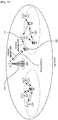
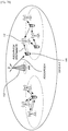
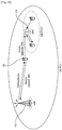
- FIG. 1 is an exemplary diagram illustrating a wireless communication system to which at least one embodiment may be applied.
- wireless communication system 100 may be one of a coordinated multi-point transmission/reception (CoMP) system, a coordinated multi-antenna transmission system, and a coordinated multi-cell communication system.
- the CoMP system may transmit signals through cooperation between a plurality of transmission/reception points.
- Wireless communication system 100 such as a CoMP system may include a plurality of transmission/reception points 110 and 112, and at least one user equipment (UE) 120 and 122.
- UE user equipment
- the transmission/reception points may be, as shown in the figure, one of eNB 110 and RRH 112.
- eNB 110 may be a base station or a macrocell (or macronode).
- RRH 112 may be at least one picocell which is wiredly controlled by coupling to eNB 110 through an optical cable or an optical fiber.
- RRH 112 may have either a high transmission power, or a low transmission power within a macrocell region.
- Transmission/reception points eNB 110 and RRH 112 may have the same cell identity (ID) or different cell identities.
- ID cell identity
- a downlink may represent communication or a communication path from transmission/reception points 110 and 112 to user equipment 120.
- An uplink (UL) may represent communication or a communication path from user equipment 120 to transmission/reception points 110 and 112.
- a transmitter may be a portion of transmission/reception points 110 and 112
- a receiver may be a portion of user equipment 120 and 122.
- a transmitter may be a portion of user equipment 120, and a receiver may be a portion of transmission/reception points 110 and 112.
- a situation in which a signal is transmitted or received through such channels as PUCCH, PUSCH, PDCCH, and/or PDSCH may be referred to as the expression of "transmit or receive PUCCH, PUSCH, PDCCH, and/or PDSCH.”
- eNB 110 corresponding to one of transmission/reception points (e.g., 110, 112) may perform a downlink transmission to user equipment 120 and 122.
- eNB 110 may transmit PDSCH corresponding to a primary physical channel, for unicast transmission.
- eNB 110 may transmit PDCCH in order to transmit downlink control information, such as scheduling information required for receiving PDSCH, and to transmit scheduling grant information for an uplink shared channel (e.g., PUSCH) transmission.
- downlink control information such as scheduling information required for receiving PDSCH
- scheduling grant information for an uplink shared channel (e.g., PUSCH) transmission may be referred to as the expression of "transmit or receive a channel.”
- UE 1 (120) may transmit an uplink signal to eNB 110.
- UE 2 (122) may transmit an uplink signal to RRH 112 corresponding to one of transmission/reception points 110 and 112.
- UE 1 (120) may transmit an uplink signal to RRH 112
- UE 2 (122) may transmit an uplink signal to eNB 110.
- the number of user equipment may be "2" or more. In the following embodiments, descriptions will be given under the assumption that one of two user equipment transmits an uplink signal to eNB 110, and the other transmits an uplink signal to RRH 112, though the present invention is not so limited.
- a demodulation reference signal (DMRS or DM-RS) and an SRS may be defined for an uplink.
- Three types of reference signals (RSs) may be defined for a downlink.
- the three types of the reference signals (RSs) may include a cell-specific reference signal (CRS), a multicast/broadcast over single frequency network reference signal (MBSFN-RS), and a UE-specific reference signal.
- a wireless communication system when performing an uplink transmission, user equipment may transmit an uplink demodulation reference signal (UL DMRS or UL DM-RS) per slot such that channel information for demodulation of data channels is recognized.
- UL DMRS uplink demodulation reference signal
- user equipment may transmit a reference signal through one symbol per slot.
- a reference signal may be transmitted through three symbols per slot.
- PUCCH formats 2, 2a, 2b, and 3 a reference signal may be transmitted through two symbols per slot.
- FIG. 2 illustrates a typical method of performing uplink/downlink data transmissions in a CoMP scenario environment and/or a heterogeneous network environment in which transmission/reception points use different cell identities .
- wireless communication system 100 to which at least one embodiment is applied may be a CoMP system implementing a CoMP scenario or a heterogeneous network in which eNB110 and RRH 112 have different cell identities.
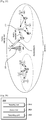
- FIG. 3 illustrates a method of performing uplink/downlink data transmissions in a CoMP scenario environment in which transmission/reception points use the same cell identity.
- wireless communication system 100 to which at least one embodiment is applied may be a CoMP system implementing a CoMP scenario in which eNB110 and RRHs 112a through 112f have the same cell identity.
- user equipment may receive parameters for generation of reference signals, from a corresponding transmission/reception point to which the user equipment belongs.
- the parameter for reference signal generation may include information on at least one of a sequence group number, a base sequence number, a cyclic shift index, and an orthogonal cover code (OCC) index.
- OCC orthogonal cover code
- the reference signals transmitted by user equipment in wireless communication system 100 may be generated based on the parameters for reference signal generation.
- the corresponding transmission/reception point may be eNB 110 corresponding to a serving transmission/ reception point.
- each user equipment may be classified by reference numerals 120a, 120b, 120c, or the like.
- the one user equipment may be denoted by reference numeral 120.
- eNB 110 may inform user equipment of a corresponding cell identity such that eNB 110 can be identified, and inform the user equipment of a sequence group number and a base sequence number, according to the configuration of sequence-group hopping and sequence hopping determined through radio resource control (RRC). Furthermore, in another operation (“operation 2"), eNB 110 may inform user equipment of PDCCH for an uplink grant, transmitted through a downlink. For example, eNB 110 may inform user equipment of a cyclic shift index and an OCC index for generation of a reference signal to be transmitted by user equipment 120a, through downlink control information (DCI) format 0 and DCI format 4. User equipment may generate an uplink DM-RS, and transmit the generated uplink DM-RS and PUSCH to eNB 110, through the operation 1 and the operation 2.
- DCI downlink control information
- a certain transmission/reception point or a certain cell in wireless communication system 100 may transmit parameters for SRS generation (i.e., parameters for generation of the SRS transmitted by user equipment) to the user equipment.
- the parameters for SRS generation may include a cell-specific SRS bandwidth, a transmission comb, a UE-specific SRS bandwidth, hopping related configuration parameters, a frequency domain position, a periodicity, a subframe configuration (designating which subframe will transmit an SRS), an antenna configuration (designating the number of antennas transmitting an SRS and the number of antenna ports), a base sequence index, a cyclic shift index (i.e., a reference signal to be used for SRS generation), and so forth.
- transmission comb may designate frequency positions assigned at intervals of two types of subcarrier spacing. For example, "0" may denote even subcarriers and "1" denote odd subcarriers.
- the base sequence index may be an SRS sequence index for generating a corresponding SRS.
- the SRS sequence index may be determined, based on sequence group number u used in PUCCH and base sequence number v defined according to a sequence hopping configuration used for PUSCH.
- a corresponding transmission/reception point e.g., eNB 110
- User equipment 120a may receive the parameters for SRS generation from eNB 110, and transmit an uplink SRS to eNB 110.
- an aperiodic SRS may be defined along with a periodic SRS.
- parameters to be used for generation of the aperiodic SRS may be transmitted, as RRC parameters, to user equipment 120a by a certain transmission/reception point.
- the parameters for generation of the aperiodic SRS may include a UE-specific SRS bandwidth of aperiodic SRS, a transmission comb, a frequency domain position, a periodicity, a subframe configuration, an antenna configuration, a base sequence index, a cyclic shift index, and so forth, as defined in wireless communication system 100.
- a certain transmission/reception point may dynamically trigger user equipment 120a through PDCCH such that user equipment 120a can transmit a periodic SRS.
- user equipment 120a may transmit an uplink aperiodic SRS.
- the expression “receive the reference signal” may mean that the reference signal is received not as interference but as a desired signal. That is, the expression may mean that the reference signal is received to meet a purpose of the reference signal transmitted by user equipment.
- user equipment When receiving parameters from a certain transmission/reception point, user equipment may generate reference signals, such as an uplink DM-RS and/or periodic/ aperiodic SRSs, based on the received parameters. Accordingly, user equipment may perform an uplink transmission only through an uplink associated with a downlink of the certain transmission/reception point to which the user equipment belongs. In other words, user equipment may not perform an uplink transmission through an uplink not being associated with the downlink of the certain transmission/reception point to which the user equipment belongs.
- reference signals such as an uplink DM-RS and/or periodic/ aperiodic SRSs
- user equipment 120a belonging to the certain transmission/reception point may not perform an uplink transmission to a different transmission/reception point (i.e., a transmission/reception point different from the certain transmission/reception point).
- the different transmission/reception point may provide an uplink channel having a comparatively better uplink channel quality and/or a comparatively better geometry.
- a method may be provided for supporting an uplink transmission to a different transmission/reception point. More specifically, according to the method, user equipment 120a belonging to a certain transmission/ reception point (i.e., user equipment 120a receiving a downlink control channel from the certain transmission/reception point) may perform an uplink transmission to a different transmission/reception pointwhich provides an uplink channel having a comparatively better channel quality and/or a comparatively higher geometry. Furthermore, in at least one embodiment, a method and an apparatus may be provided for differentiating channels transmitted to different transmission/reception points.
- a method and an apparatus may be provided for differentiating between an uplink channel (e.g., PUSCH, PUCCH, SRS, and/or an uplink related RS) which user equipment transmits to a corresponding transmission/reception (i.e., a corresponding transmission/reception to which the user equipment belongs) and an uplink channel which the user equipment transmits to a transmission/reception points other than the corresponding transmission/reception.
- an uplink channel e.g., PUSCH, PUCCH, SRS, and/or an uplink related RS
- Such channel differentiation may be differentiation between different type channels such as between SRS and PUSCH, between PUCCH and PUSCH, between PUCCH and SRS, and so forth.
- a sequence group number and a base sequence number used for periodic and aperiodic SRSs may be defined from a sequence group number u and a base sequence number v , respectively.
- the sequence group number u may be used for PUCCH.
- the base sequence number v may be defined in sequence hopping used for PUSCH.
- a method and an apparatus may be provided for differently defining the sequence group number u and the base sequence number v used for periodic and aperiodic SRSs.
- Embodiment 1 determines a receiving subject (i.e., a target transmission/ reception point) of an SRS independently from receiving subjects of PUCCH and/or PUSCH by generating an SRS sequence independently from the PUCCH, a reference signal sequence associated with the PUCCH, the PUSCH, and a reference signal sequence associated with the PUSCH; and ii) Embodiment 2 transmits an SRS without association with PUCCH and PUSCH, to a serving transmission/reception point.
- a receiving subject i.e., a target transmission/ reception point
- a sequence group number and a base sequence number for SRS generation may be independently generated, without deriving from PUCCH sequence group number or PUSCH base sequence number based on a cell identity of a serving cell.
- a sequence group number and a base sequence number for SRS generation may be further included in RRC configuration parameters.
- a sequence group number and a base sequence number for SRS generation may be dynamically indicated by transmitting the predefined parameter through PDCCH or EPDCCH.
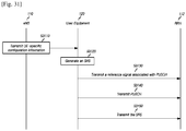
- FIG. 4 is a flowchart illustrating a method of transmitting an SRS in accordance with Embodiment 1 of the present invention.
- user equipment 120 may receive UE-specific configuration information indicating an SRS identity from one transmission/reception point (e.g., eNB110) of a plurality of different transmission/reception points at step S410.
- the SRS identity is independently determined to be distinguished from an uplink reference signal identity for an uplink channel.
- user equipment 120 may generate an SRS using the independently determined SRS identity.
- user equipment 120 may perform a physical uplink channel transmission to eNB110.
- user equipment 120 may transmit the generated SRS to a transmission/reception point (e.g., RRH 112) indicated by the independently determined SRS identity.
- a transmission/reception point e.g., RRH 112
- an uplink reference signal identity for an uplink channel and an SRS identity may be independently determined. Accordingly, a receiving subject (e.g., eNB 110) of the uplink channel and a receiving subject (e.g., RRH 112) of the SRS may be different.
- the expressions “independent,” and “independently” may mean that an SRS identity is separately defined without association with other uplink reference signal identities and/or a physical cell identity of a serving transmission/ reception point serving user equipment. Accordingly, the SRS identity may be the same as or different from the other uplink reference signal identities and/or the physical cell identity of the serving transmission/reception point.
- an SRS is transmitted independently from an uplink channel
- an SRS may be independently transmitted when other channel transmissions are not performed.
- an SRS and at least a portion of an uplink channel i.e., all or a portion of an uplink channel may be simultaneously transmitted in one subframe.
- an uplink channel may correspond to at least one of PUSCH and PUCCH.
- An SRS may be at least one of a periodic SRS and an aperiodic SRS.
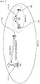
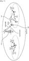
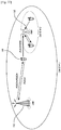
- FIG. 5 illustrates independently transmitting a physical uplink channel and an SRS in a CoMP environment in which transmission/reception points use different cell identities (e.g., cell ID #1 and cell ID #2).
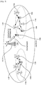
- FIG. 6 illustrates independently transmitting a physical uplink channel and an SRS in a CoMP environment in which transmission/reception points use the same cell identity (e.g., cell ID #0).
- a receiving subject of a physical uplink channel and a receiving subject of an SRS may be independently determined since an identity for SRS generation is determined independently from an identity for a physical uplink reference signal. Accordingly, even though it is not shown in figures, the physical uplink channel and the SRS may be transmitted to different receiving subjects or the same receiving subject. In this case, it may be necessary to independently determine each receiving subject of the physical uplink channel and the SRS.
- an SRS sequence may be determined independently from DM-RS associated with PUCCH and/or PUSCH.
- a TDD system may independently measure a downlink channel quality of a serving transmission/reception point and a downlink channel quality of a different transmission/reception point (i.e., a transmission/reception point different from the serving transmission/reception point).
- the TDD system may use an uplink channel quality measurement and a channel reciprocity for the serving transmission/reception point and the different transmission/reception point.
- the SRS transmission method may allow for recognition of a location or a geometry of user equipment, using an SRS. Accordingly, in the case that user equipment is located on edge of a cell or at the center of the cell, improvement of data throughput in a downlink by using a UE-specific downlink transmission method may be possible.
- receiving subjects of a periodic SRS and an aperiodic SRS may be the same. That is, a UE-specific parameter indicating an SRS identity may indicate the same reference signal identity for the periodic SRS and the aperiodic SRS.
- SRS identities for generating a periodic SRS and an aperiodic SRS may be independent each other.
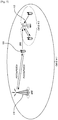
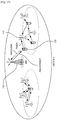
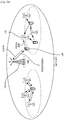
- FIG. 7 illustrates independently transmitting not only a physical uplink channel and an SRS but also a periodic SRS and an aperiodic SRS, in a CoMP environment in which transmission/reception points use different cell identities (e.g., cell ID #1, cell ID #2, and cell ID #3).
- cell identities e.g., cell ID #1, cell ID #2, and cell ID #3.
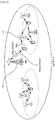
- FIG. 8 illustrates independently transmitting not only a physical uplink channel and an SRS but also a periodic SRS and an aperiodic SRS, in a CoMP environment in which transmission/reception points use the same cell identity (e.g., cell ID #0).
- UE-specific configuration information indicating an SRS identity may indicate a different reference signal identity for each of the periodic SRS and the aperiodic SRS.
- the SRS may be transmitted independently from PUCCH and PUSCH.
- the periodic SRS and the aperiodic SRS may be transmitted independently from each other.
- FIG. 7 and FIG. 8 illustrate only a case that a receiving subject (e.g., 112b or 110) of the periodic SRS and a receiving subject (e.g., 112a) of the aperiodic SRS are different.
- each receiving subject for periodic/aperiodic SRSs may be independently determined, and the two receiving subjects may be the same.
- an SRS sequence may be determined independently from DM-RS associated with PUCCH and/or PUSCH. Furthermore, sequences for a periodic SRS and an aperiodic SRS may be independently determined. Accordingly, a TDD system may independently measure a downlink channel quality of a serving transmission/reception point and a downlink channel quality of a different transmission/reception point. Herein, the TDD system may use an uplink channel quality measurement and a channel reciprocity for the serving transmission/reception point and the different transmission/reception point.
- Such SRS transmission method may allow for recognition of a location or a geometry of user equipment, using an SRS. Accordingly, in the case that user equipment is located on edge of a cell or at the center of the cell, improvement of data throughput for a downlink by using a UE-specific downlink transmission method may be possible.
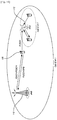
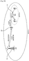
- FIG. 9 illustrates transmitting a periodic SRS to a serving transmission/ reception point serving user equipment, and transmitting an aperiodic SRS to a different transmission/reception point, in a CoMP environment in which transmission/reception points use different cell identities (e.g., cell ID #1 and cell ID #2).
- cell identities e.g., cell ID #1 and cell ID #2.
- FIG. 10 illustrates transmitting a periodic SRS to a serving transmission/ reception point serving user equipment, and transmitting, independently from a physical uplink channel, an aperiodic SRS to a different transmission/reception point, in a CoMP environment in which transmission/reception points use the same cell identity (e.g., cell ID #0).
- an aperiodic SRS may be transmitted to a serving transmission/ reception point serving user equipment.
- a periodic SRS may be independently transmitted from a physical uplink channel, to another transmission/reception point.
- one of a periodic SRS and an aperiodic SRS may be generated using an SRS identity, and the other SRS may be generated using a cell identity of a serving transmission/reception point serving user equipment.
- the SRS identity may be independently distinguished from an identity for a physical uplink channel.
- SRS transmission procedure (S430) one of the periodic SRS and the aperiodic SRS may be transmitted to a transmission/reception point indicated by the SRS identity, and the other SRS may be transmitted to the serving transmission/reception point.
- one of the periodic SRS and the aperiodic SRS may be transmitted independently from a physical uplink channel, and the other may be transmitted to the serving transmission/reception point.
- a receiving subject of the SRS transmitted independently may be the same as a receiving subject of the physical uplink channel.
- the SRS may be transmitted to the serving transmission/reception point.
- the SRS identity may be independently distinguished from an uplink reference signal identity for a physical uplink channel.
- the uplink reference signal identity may be a reference signal identity of an uplink demodulation reference signal (UL DMRS or UL DM-RS).
- UE-specific configuration information may include UE-specific parameters which are specifically determined for user equipment 120 belonging to eNB 110.
- UE-specific configuration information may include reference signal identities associated with a physical uplink channel (e.g., PUCCH or PUSCH).
- the reference signal identities associated with the physical uplink channel may be used to determine a UE-specific physical uplink channel sequence and a UE-specific reference signal sequence associated with a physical uplink channel.
- the UE-specific configuration information may include UE-specific parameters indicating the reference signal identity n ID RS associated with PUCCH or a virtual cell identity (VCID) (hereinafter, referred to as n ID RS and a reference signal identity n ID RS ′ as-sociated with PUSCH.
- n ID RS reference signal identity
- n ID RS ′ reference signal identity RS ′
- the reference signal identity n ID RS associated with the PUCCH and the reference signal identity n ID RS ′ associated with the PUSCH may be different from or the same as a cell-specific parameter indicating a cell identity N ID cell of a cell to which user equipment 120 belongs.
- the eNB 110 may dynamically transmit UE-specific configuration information to user equipment 120 through PDCCH/EPDCCH.
- the UE-specific configuration information may include UE-specific parameters indicating a reference signal identity n ID RS associated with PUCCH and a reference signal identity n ID RS ′ associated with PUSCH.
- the UE-specific configuration information may be determined semi-statically by higher layers such as RRC layer, or be determined in advance through RRC.
- eNB 110 may provide indication information for use of the pre-determined UE-specific configuration information, through PDCCH/ EPDCCH.
- user equipment 120 may generate a base sequence for each of a reference signal associated with PUCCH and/or a reference signal associated with PUSCH, using UE-specific configuration information.
- the UE-specific configuration information may include a reference signal identity n ID RS associated with the PUCCH and/or a reference signal identity n ID RS ′ associated with the PUSCH.
- user equipment 120 may generate a base sequence r u , v ( n ) for DM-RS.
- Such base sequence (e.g., a base sequence for the PUSCH and a base sequence for the PUCCH) may be differently generated according to a sequence group number u and a base sequence number v within a corresponding sequence group.
- the reference signal identity n ID RS associated with the PUCCH and/or the reference signal identity n ID RS ′ associated with the PUSCH may be used in place of a cell ID N ID cell , to determine the sequence group number u and the base sequence number v within the corresponding sequence group.
- User equipment 120 may transmit a DM-RS through an assigned radio resource to a transmission/reception point (e.g., RRH 112) indicated by a reference signal identity.
- the DM-RS may be generated using a base sequence, a cyclic shift, and an orthogonal code (or an orthogonal cover code).
- user equipment 120 may transmit the uplink DM-RS using a maximum of three symbols per slot.
- user equipment 120 may transmit PUCCH or PUSCH through the same frequency band as a frequency band assigned for an uplink DM-RS associated with each of PUCCH and PUSCH.
- a transmission/reception point e.g., RRH 112 capable of receiving DM-RS, among transmission/reception points may receive the PUCCH and the PUSCH, using a received DM-RS.
- receiving subjects of PUCCH/PUSCH may be determined as a serving transmission/reception point 110, but the present invention is not limited thereto.
- Receiving subjects of PUCCH/PUSCH may be arbitrarily determined based on a reference signal identity n ID RS associated with the PUCCH and/or a reference signal identity n ID RS ′ associated with the PUSCH. Accordingly, the receiving subjects of the PUCCH and the PUSCH may be determined as a transmission/reception point other than a serving transmission/reception point 110.
- user equipment 120 may receive UE-specific configuration information.
- the UE-specific configuration information may include an SRS identity n ID SRS determined independently.
- user equipment 120 may generate an SRS, using the received UE-specific configuration information including the independently determined SRS identity n ID SRS .
- SRS generation procedure S420
- An SRS sequence may be generated by a cyclic shift (CS) of a base sequence r u , v ( n ) based on Zadoff-Chu sequence, as described by Formula 1 and Formula 2 below.
- the generated SRS sequence may have length M sc RS based on resource blocks (RBs) used for an SRS transmission.
- RBs resource blocks
- the length M sc RS of the SRS sequence [Number of RSs] ⁇ [Number of subcarriers (typically, 12) within an RB] /2.
- r u , v ⁇ p ⁇ n denotes a reference signal (RS) sequence
- ⁇ p ⁇ denotes a cyclic shift (CS)
- r u ,v( n ) denotes a base sequence
- M sc RS mN sc RB , 1 ⁇ m ⁇ N RB max , UL
- M sc RS is the number of subcarriers assigned for UL RS sequence in the frequency domain.
- Base sequences may be differently generated according to the sequence group number u , the base sequence number v within the group, and a sequence length n .
- sequence groups may be hopped per slot regardless of the number of resource blocks (RBs) assigned to user equipment.
- RBs resource blocks
- sequence group number u in slot n s may be defined by a group hopping pattern f gh ( n s ) and a sequence-shift pattern f ss , according to Formula 3 below.
- u f gh n s + f ss mod 30
- the sequence group hopping pattern f gh ( n s ) may be the same for PUCCH and PUSCH. However, the sequence-shift pattern f ss may be different for PUCCH and PUSCH.
- the group-hopping pattern f gh ( n s ) may be given by Formula 4 below.
- f gh n s ⁇ 0 if group hopping is disabled
- ⁇ i 0 7 c 8 n s + i ⁇ 2 i mod 30 if group hopping is enabled
- c ( i ) denotes a pseudo-random sequence.
- sequence-shift pattern f ss may be different between PUCCH, PUSCH and SRS.
- Sequence hopping may be applied for reference signals of length 6 RBs or larger ( M sc RS ⁇ 6 N sc RB ) .
- the base sequence number v within the base sequence group in slot n s may be defined by Formula 5 below.
- c ( i ) denotes a pseudo-random sequence.
- the cyclic shift ⁇ p ⁇ may be differently generated for each user equipment and for each antenna port, according to Formula 6 below.
- n SRS CS used to calculate the cyclic shift ⁇ p ⁇ may be transmitted by higher-layer signaling (e.g., RRC).
- RRC higher-layer signaling
- Cyclic shift ⁇ p ⁇ for each antenna port may be determined based on the transmitted n SRS CS as described in Formula 6.
- p ⁇ denotes an antenna port number index
- N ap denotes the number of antenna ports used for an SRS transmission.
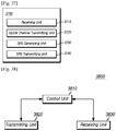
- An SRS sequence may be generated according to Formula 1 using the base sequence of Formula 2 and the cyclic shift (CS) ⁇ p ⁇ of Formula 6. Such SRS sequence generation procedure may be performed in OFDM modulator 2010 shown in FIG. 20 .
- user equipment 120 may assign radio resources for SRS transmission, and transmit the generated SRS (e.g., an SRS generated at step S420) through the assigned radio resources, to a transmission/reception point (e.g., RRH 112) indicated by n ID SRS .
- a transmission/reception point e.g., RRH 112
- a UE-specific parameter indicating an uplink reference signal identity may indicate the same reference signal identity for a periodic SRS and an aperiodic SRS.
- sequence group numbers and base sequence numbers for the periodic SRS and the aperiodic SRS may be determined as the same value.
- the sequence group numbers and the base sequence numbers for the periodic or aperiodic SRS may be determined independently from a sequence group number and a base sequence number for PUCCH and PUSCH.
- an SRS sequence may be determined independently from PUCCH and PUSCH.
- a TDD system may independently measure a downlink channel quality of a serving transmission/reception point and a downlink channel quality of a different transmission/reception point.
- the TDD system may use an uplink channel quality measurement and a channel reciprocity for the serving transmission/ reception point and the different transmission/reception point.
- the SRS transmission method may allow for recognition of a location or a geometry of user equipment, using an SRS. Accordingly, in the case that the user equipment is located on edge of a cell or at the center of the cell, it may be possible to improve data throughput for a downlink by using a UE-specific downlink transmission method.
- sequence group numbers and base sequence numbers used for a periodic SRS and an periodic SRS may be assigned independently from each other, through RRC parameters.
- indication information for corresponding base sequence numbers and sequence group numbers may be included in PDCCH transmitted dynamically.
- base sequence numbers and sequence group numbers used for a periodic SRS and an periodic SRS may be dynamically indicated through a RRC parameter (e.g., a parameter having a length of 1 bit) predefined by RRC signaling.
- an SRS sequence may be generated independently from PUCCH and PUSCH.
- user equipment may transmit an SRS to a serving transmission/ reception point or a different transmission/reception point. Therefore, a transmission/ reception point (e.g., a base station) received the SRS may flexibly perform a scheduling procedure.
- a transmission/ reception point e.g., a base station
- a transmission to a serving transmission/ reception point and a transmission to a different transmission/reception point may be independently performed.
- a UE-specific parameter indicating an SRS identity may indicate different reference signal identities for a periodic SRS and an aperiodic SRS.
- a sequence group number and a base sequence number for the periodic SRS may be determined independently form a sequence group number and a base sequence numbers for the aperiodic SRS.
- the sequence group numbers and the base sequence numbers for the periodic and aperiodic SRSs may be determined independently from a sequence group number and a base sequence number for PUCCH and PUSCH.
- an SRS may be generated using a periodic SRS identity n ID SRS , and the generated SRS may be transmitted to a transmission/ reception point indicated by the periodic SRS identity n ID SRS .
- an SRS may be generated using an aperiodic SRS identity n ID SRS ′ being independent of a periodic SRS identity n ID SRS .
- the generated SRS may be transmitted to a transmission/reception point indicated by the aperiodic SRS identity n ID SRS ′ .
- the periodic SRS identity n ID SRS and the aperiodic SRS identity n ID SRS ′ may inde-pendently indicate a corresponding transmission/reception point for SRS transmission.
- the periodic SRS identity n ID SRS and/or the aperiodic SRS identity n ID SRS ′ may not necessarily indicate a serving transmission/reception point.
- the periodic SRS identity n ID SRS and/or the aperiodic SRS identity n ID SRS ′ may indicate a certain transmission/reception points (e.g., eNB 110) other than the serving transmission/reception point.
- an SRS sequence may be determined independently from PUCCH and PUSCH. Furthermore, sequences for a periodic SRS and an aperiodic SRS may be independently determined from each other. Accordingly, a TDD system may independently measure a downlink channel quality of a serving transmission/reception point and a downlink channel quality of a different transmission/reception point. Herein, the TDD system may use an uplink channel quality measurement and a channel reciprocity for the serving transmission/reception point and the different transmission/reception point.
- the SRS transmission method may allow for recognition of a location or a geometry of user equipment, using an SRS. Accordingly, in the case that user equipment is located on edge of a cell or at the center of the cell, it may be possible to improve data throughput for a downlink by using a UE-specific downlink transmission method.
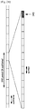
- FIG. 21 illustrates a position of a symbol carrying an SRS.
- FIG. 22 illustrates a non-frequency hopping SRS and a frequency hopping SRS.
- an SRS may be transmitted by the last symbol of a subframe.
- SRS transmissions should cover the frequency band that is of interest for a frequency-domain scheduling.
- a sufficiently wideband SRS transmission may be performed such that channel quality of an entire frequency band of interest can be estimated with a single SRS transmission.
- a sequence of SRS transmissions may jointly cover the entire frequency band of interest, by transmitting a narrowband SRS using hopping in the frequency domain.
- SC-FDMA symbols may be generated by a SC-FDMA generator (not shown in FIG. 20 ). SRS signals corresponding to the generated SC-FDMA symbols may be transmitted to a corresponding transmission/reception point.
- Specific subframes carrying SRSs may be periodically or aperiodically determined.
- “cell-specific subframes for SRS transmission” (hereinafter, referred to as “cell-specific SRS subframes”) may be configured or defined as shown in Table 1or Table 2 below.
- Table land Table 2 may be associated with frequency division duplex (FDD) and time division duplex (TDD), respectively.
- An SRS may be periodically transmitted in subframes which have a specific configuration period T SFC and a specific transmission offset ⁇ SFC in each user equipment.
- Such SRS may be referred to as a periodic SRS or a trigger type 0 SRS.
- an SRS may be transmitted in subframes which are aperiodically configured. In this case, such SRS may be referred to as an aperiodic SRS or a trigger type 1 SRS.
- Table 1 and Table 2 may represent cell-specific SRS subframes as configuration period T SFC and transmission offset ⁇ SFC for FDD (frame structure type 1) and TDD (frame structure type 2).
- the total number of possible cases may be 16.
- the parameter "srs-SubframeConfig" for each case may be transmitted by higher-layer signaling of 4bits, such as RRC signaling.
- a corresponding configuration period T S FC may be "5" and a corresponding transmission offset ⁇ SFC may be ⁇ 0,1 ⁇ .
- an SRS may be transmitted in the first and second subframes per five subframes corresponding to the configuration period.
- the periodic SRS may represent an SRS transmitted in corresponding subframes which are periodically transmitted according to a specific configuration period T SFC and a specific transmission offset ⁇ SFC in each user equipment, among the above-described cell-specific SRS subframes.
- Table 3 (FDD) and Table 4 (TDD) below may represent a periodicity and an offset of a UE-specific periodic SRS.
- the UE-specific periodic SRS may represent a periodic SRS defined according to each user equipment.
- Table 3 and Table 4 may represent UE-specific periodic SRS subframes as periodicity T SRS and offset T offset for FDD and TDD.
- UE-specific periodic SRS subframes may be subframes transmitting a UE-specific periodic SRS.
- the total number of possible cases may be 1024.
- SRS configuration index I SRS for each case may be transmitted by higher-layer signaling of 10 bits, such as RRC signaling.
- RRC signaling For example, in Table 3, in the case that the SRS configuration index I SRS is 3, a corresponding periodicity T SRS is "5" and a corresponding offset T offset is "1".
- a UE-specific periodic SRS may be transmitted in the second subframe per five subframes corresponding to a periodicity.
- the information on RBs may include the number of "cell-specific occupied RBs" (i.e., all RBs being used for certain cell). More specifically, in case of the cell-specific occupied RBs, occupied RBs (i.e., in-use RBs) may represent specific RBs corresponding to the number of higher-layer signaling among all RBs corresponding to an entire system bandwidth (BW). For example, in the case that system bandwidth is 50 RBs and the number of signaling RBs is 48, it may mean that 48 RBs are used among a total of 50 RBs. Furthermore, the information on RBs may include the number of and positions of "UE-specific occupied RBs" (i.e., RBs being used by a certain user equipment among the cell-specific occupied RBs).
- UE-specific occupied RBs i.e., RBs being used by a certain user equipment among the cell-specific occupied RBs.
- Table 5 may be used in the case that a system bandwidth (e.g., an uplink bandwidth) is 40 to 60 RBs.
- a system bandwidth e.g., an uplink bandwidth
- Table 5 may be differently defined according to corresponding system bandwidths.
- the number of cell-specific occupied RBs may be transmitted as the parameter C SRS .
- the number of UE-specific occupied RBs may be defined as the parameter B SRS .
- the parameter n RRC may be defined in order to represent positions of RBs used for each user equipment.
- Such parameters e.g., C SRS , B SRS , n RRC
- Such parameters may be transmitted by higher-layer signaling such as RRC signaling.
- information on subcarriers assigned for an SRS may be transmitted by higher-layer signaling such as RRC.
- the transmission comb may be expressed as the parameter k TC , and the parameter k TC may be set as "0" or "1".
- the parameter k TC may indicate whether subcarriers substantially transmitting an SRS sequence through a mapping process are even-numbered subcarriers or odd-numbered subcarriers.
- the transmission comb may also be transmitted by higher-layer signaling (e.g., RRC signaling) performed for each user equipment.
- a transmission unit may transmit the following SRS transmission related parameters to user equipment such that the user equipment can transmit a periodic SRS or a trigger type 0 SRS.
- SRS transmission related parameters may include i) parameters (e.g., srs--SubframeConfig, I S RS ) used for determination of subframes transmitting an SRS, ii) parameters (e.g., C SRS , B SRS , n RRC ) used for determination of resource blocks (RBs) transmitting an SRS, iii) a parameter (e.g., k TC ) used for determination of subcarriers assigned for SRS transmission, iv) a parameter (e.g., n SRS CS ) used for deter-mination of cyclic shifts between SRSs, and v) the number of antenna ports.
- Such SRS transmission related parameters may be transmitted by a higher-layer signaling (e.g., R
- an SRS may be transmitted in SRS subframes which are aperiodically configured, among cell-specific SRS subframes determined by Table 1 (FDD) or Table 2 (TDD).
- SRS may be referred to as an aperiodic SRS or a trigger type 1SRS.
- an SRS may be aperiodically transmitted in UE-specific subframes determined according to Table 7 (FDD) or Table 8 (TDD), among cell-specific SRS subframes determined by Table 1 or Table 2.
- the UE-specific subframes may have a specific periodicity and a specific offset defined according to a corresponding user equipment as described in Table 7 or Table 8.
- the expression "SRS is aperiodically transmitted" may mean that after some possible cases for SRS transmission are pre-defined, SRS transmission associated with such pre-defined cases may be triggered by dynamic signaling such as downlink control information (DCI), if necessary.
- DCI downlink control information
- signaling information for SRS transmission may be directly transmitted by higher-layer signaling.
- the signaling information for SRS transmission may include at least one of i) information on SRS transmission subframes, ii) information on SRS transmission resource blocks (RBs), iii) information on subcarriers assigned for SRS transmission, iv) information on cyclic shift used for SRS sequence generation, and v) the number of antenna ports for SRS transmission.
- some of signaling information for SRS transmission may not be directly transmitted to user equipment.
- the SRS parameter set associated with the some signaling information may be pre-defined by higher-layer signaling (e.g., RRC signaling). Accordingly, only when an SRS transmission is necessary, only a value indicating the pre-defined SRS parameter set may be transmitted by a dynamic signaling such as DCI.
- RRC signaling e.g., RRC signaling
- an SRS parameter set may include i) the parameter I SRS used to determine SRS transmission subframes, ii) the parameters B SRS and n RRC used to determine SRS transmission resource blocks (RBs), iii) the parameter k TC used to determine subcarriers assigned for SRS transmission, iv) the parameter n SRS CS used to determine a cyclic shift of SRS, and v) the number of antenna ports.
- the parameters srs-SubframeConfig and C SRS may not be included in the SRS parameter set.
- Table 9 below may represent SRS parameters which are included or excluded in the SRS parameter set.
- a trigger signal of an aperiodic SRS may have a length of 1 bit.
- values transmitted through the trigger signal may be as described in Table 10 below.
- a trigger signal of an aperiodic SRS may have a length of 2bits.
- values transmitted through the trigger signal may be as described in Table 11 below.
- an aperiodic SRS (or a type 1 SRS) may not be transmitted.
- the aperiodic SRS (or the type 1 SRS) may be transmitted, according to parameters included in a corresponding SRS parameter set.
- the SRS parameter set may be configured by higher-layer signaling in advance.
- independent transmission of periodic/aperiodic SRS(s) may allow for estimation of a channel state of uplink associated with a transmission/reception points (i.e., a different transmission/ reception point) other than a serving transmission/reception point. Accordingly, it may be possible to overcome a shortage of uplink coverage.
- a TDD system may independently measure a downlink channel quality of a serving transmission/reception point and a downlink channel quality of a different transmission/reception point.
- the TDD system may use an uplink channel quality measurement and a channel reciprocity for the serving transmission/reception point and the different transmission/reception point.
- the SRS transmission method may allow for recognition of a location or a geometry of user equipment, using an SRS. Accordingly, in the case that user equipment is located on edge of a cell or at the center of the cell, improvement of data throughput for a downlink by using a UE-specific downlink transmission method may be possible.
- user equipment When performing a blind decoding of PDCCH according to a sequence configuration of a corresponding SRS, user equipment may perform the following procedure in order to detect a corresponding uplink grant.
- indication information for a related base sequence number may be included in PDCCH, or the related base sequence number may be dynamically indicated by RRC parameters (e.g., a parameter having a length of 1bit) predefined by RRC signaling.
- RRC parameters e.g., a parameter having a length of 1bit
- the uplink grant may include uplink scheduling information for the user equipment.
- DCI format 0 and DCI format 4 may correspond to the uplink grant. Accordingly, the user equipment may be configured to monitor the UE specific search space for the uplink grant including the uplink scheduling information when performing a search for PDCCH.
- a physical uplink channel may be generated using a reference signal identity, and an SRS may be generated using a physical cell identity of a serving transmission/reception point.
- At least one of aperiodic and periodic SRSs may be not associated with PUCCH and PUSCH such that the at least one of the aperiodic and periodic SRSs is not subject to configuration of PUCCH/PUSCH sequences. Therefore, a receiving subject for the at least one of aperiodic and periodic SRSs may be determined as the serving transmission/reception point. Meanwhile, a reception point for PUSCH or PUCCH may be determined as a transmission/reception point other than the serving transmission/reception point (i.e., a downlink transmission subject).
- a corresponding receiving subject may be determined as a different transmission/reception point (i.e., a transmission/reception points other than the serving transmission/reception point), by defining UE-specific PUSCH/PUCCH reference signal sequences. Accordingly, a receiving subject of PUSCH/PUCCH and a receiving subject of an SRS may differ, and therefore PUSCH/PUCCH transmissions and an SRS transmission may be separately performed.
- FIG. 11 is a flowchart illustrating a method of transmitting an SRS in accordance with Embodiment 2 of the present invention.
- user equipment 120 may receive UE-specific configuration information indicating an uplink reference signal identity from one transmission/reception point (e.g., eNB 110) of a plurality of different transmission/reception points.
- the uplink reference signal identity may be independent of a physical cell identity of the one transmission/reception point (e.g., eNB 110) and is associated with an uplink channel.
- user equipment 120 may generate an SRS, using a physical cell identity of the one transmission/reception point.
- the one transmission/ reception point may be a transmission/reception point serving user equipment 120.
- user equipment 120 may transmit an uplink channel and related reference signals (e.g., a demodulation reference signal (DM-RS) associated with the uplink channel), using the uplink reference signal identity. More specifically, user equipment 120 may transmit to a transmission/reception point (e.g., RRH 112) indicated by the uplink reference signal identity.
- a transmission/reception point e.g., RRH 112 indicated by the uplink reference signal identity.
- user equipment 120 may transmit the generated SRS (S1120) to the one transmission/reception point, i.e., the serving transmission/reception point (e.g., eNB 110).
- the SRS may include at least one of a periodic SRS and an aperiodic SRS.
- the uplink channel may include at least one of PUCCH and PUSCH.
- a receiving subject of the uplink channel transmitted at step S1130 is determined to be a transmission/reception point (e.g., RRH 112) different from the serving transmission/reception point (e.g., eNB 110) serving user equipment 120.
- a receiving subject of an uplink channel may be independently determined by an uplink reference signal identity.
- a transmission/reception point (e.g., eNB 110) serving user equipment 120 may not necessarily be excluded from a receiving subject of the uplink channel.
- an SRS may be independently transmitted while other channels are not transmitted.
- the SRS and at least one of PUCCH and PUSCH may be simultaneously transmitted in one subframe.
- an SRS may include at least one of a periodic SRS and an aperiodic SRS.
- An uplink channel may include at least one of PUCCH and PUSCH. Accordingly, in the case that an SRS transmission is performed according to the method shown in FIG. 11 , a variety of embodiments may be present.
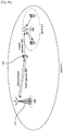
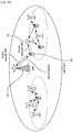
- FIG. 12 illustrates transmitting an SRS to a serving transmission/reception point when PUCCH is transmitted to a transmission/reception point other than the serving transmission/reception point, in a CoMP environment in which transmission/reception points use different cell identities (e.g., cell ID #1 and cell ID #2).
- cell identities e.g., cell ID #1 and cell ID #2.
- FIG. 13 illustrates transmitting an SRS to a serving transmission/reception point when PUCCH is transmitted to a transmission/reception point other than the serving transmission/reception point, in a CoMP environment in which transmission/reception points use the same cell identity (e.g., cell ID #0).
- the SRS may be transmitted to the serving transmission/ reception point. Accordingly, the SRS and PUCCH may be separately transmitted.
- FIG. 14 illustrates transmitting an SRS to a serving transmission/reception point when PUSCH is transmitted to a transmission/reception point other than the serving transmission/reception point, in a CoMP environment in which transmission/reception points use different cell identities (e.g., cell ID #1 and cell ID #2).
- cell identities e.g., cell ID #1 and cell ID #2.
- FIG. 15 illustrates transmitting an SRS to a serving transmission/reception point when PUSCH is transmitted to a transmission/reception point other than the serving transmission/reception point, in a CoMP environment in which transmission/reception points use the same cell identity (e.g., cell ID #0).
- the SRS may be transmitted to the serving transmission/ reception point. Accordingly, the SRS and PUSCH may be separately transmitted.
- FIG. 16 illustrates transmitting an SRS to a serving transmission/reception point when PUSCH and PUCCH are transmitted to a transmission/reception point other than the serving transmission/reception point, in a CoMP environment in which transmission/reception points use different cell identities (e.g., cell ID #1 and cell ID #2).
- cell identities e.g., cell ID #1 and cell ID #2.
- FIG. 17 illustrates transmitting an SRS to a serving transmission/reception point when PUSCH and PUCCH are transmitted to a transmission/reception point other than the serving transmission/reception point, in a CoMP environment in which transmission/reception points use the same cell identity (e.g., cell ID #0).
- the SRS may be transmitted to the serving transmission/ reception point. Accordingly, the SRS and PUSCH/PUCCH may be separately transmitted.
- an SRS generated based on a physical cell identity of a serving transmission/reception point may be at least one of a periodic SRS and an aperiodic SRS. Accordingly, the periodic SRS and the aperiodic SRS may be transmitted to the serving transmission/reception point, independently from an uplink channel. In at least one embodiment, one of the periodic SRS and the aperiodic SRS may be generated using the cell identity of the serving transmission/ reception point, and the other SRS may be generated using an uplink reference signal identity.
- a sequence group number and a base sequence number of an aperiodic SRS sequence may be defined according to a sequence configuration of PUCCH or PUSCH.
- a sequence group number and a base sequence number of the periodic SRS sequence may be defined such that the periodic SRS is transmitted to the serving transmission/reception point.
- an aperiodic SRS may be generated using a reference signal identity n ID RS associated with PUCCH or a reference signal identity n ID RS ′ associated with PUSCH, as described in Formula 1 to Formula 6. Meanwhile, a periodic SRS may be generated using a cell ID N ID cell .
- n ID RS reference signal identity
- n ID RS ′ associated with PUSCH
- a periodic SRS may be generated using a cell ID N ID cell .
- FIG. 18 illustrates transmitting a periodic SRS to a serving transmission/reception point and transmitting an aperiodic SRS in association with PUCCH when the PUCCH is transmitted to a transmission/reception point other than the serving transmission/ reception point, in a CoMP environment in which transmission/reception points use different cell identities (e.g., cell ID #1 and cell ID #2).
- cell identities e.g., cell ID #1 and cell ID #2.
- FIG. 19 illustrates transmitting a periodic SRS to a serving transmission/reception point and transmitting an aperiodic SRS in association with PUCCH when the PUCCH is transmitted to a transmission/reception point other than the serving transmission/ reception point, in a CoMP environment in which transmission/reception points use the same cell identity (e.g., cell ID #0).
- the periodic SRS may be transmitted to the serving transmission/reception point, and the aperiodic SRS may be transmitted in association with the PUCCH, but the present invention is not limited thereto.
- the aperiodic SRS may be transmitted to the serving transmission/reception point, and the periodic SRS may be transmitted in association with the PUCCH.
- the aperiodic SRS or the periodic SRS may be associated with PUSCH other than the PUCCH.
- one of a periodic SRS and an aperiodic SRS may be generated using a physical cell identity of a serving transmission/reception point (e.g., eNB 110), and the other SRS may be generated using an uplink reference signal identity.
- a serving transmission/reception point e.g., eNB 110
- the other SRS may be generated using an uplink reference signal identity.
- one of the periodic SRS and the aperiodic SRS may be transmitted to the serving transmission/reception point (e.g., eNB 110), and the other SRS may be transmitted to a transmission/reception point (e.g., RRH 112) indicated by the uplink reference signal identity.
- eNB 110 corresponding to a certain transmission/reception point may transmit UE-specific configuration information to user equipment 120 belonging to eNB 110. Accordingly, user equipment 120 may receive the UE-specific configuration information at step S1110.
- the UE-specific configuration information may include UE-specific parameters which are specifically determined for user equipment 120 belonging to eNB 110.
- the UE-specific configuration information may include UE-specific parameters indicating a reference signal identity n ID RS associated with PUCCH and a reference signal identity n ID RS ′ associated with PUSCH.
- the reference signal identity n ID RS associated with the PUCCH may be used to determine a UE-specific PUCCH sequence and a UE-specific reference signal sequence associated with the PUCCH.
- the reference signal identity n ID RS ′ associated with PUSCH may be used to determine a UE-specific PUSCH sequence and a UE-specific reference signal sequence associated with the PUSCH.
- UE-specific parameters indicating the reference signal identities n ID RS and n ID RS ′ associated with PUCCH/PUSCH may be different from a cell-specific parameter indicating a cell ID N ID cell of a cell to which ID user equipment 120 belongs.
- the eNB 110 may dynamically transmit the UE-specific configuration information to user equipment 120 through PDCCH/EPDCCH.
- the UE-specific configuration information may include UE-specific parameters indicating a reference signal identity n ID RS associated with PUCCH and a reference signal identity n ID RS ′ associated with PUSCH.
- the UE-specific configuration information may be determined semi-statically by higher layers such as RRC layer, or be determined in advance through RRC.
- eNB 110 may provide indication information for use of the pre-determined UE-specific configuration information, through PDCCH/ EPDCCH.
- user equipment 120 may generate a base sequence for each of a reference signal associated with PUCCH and/or a reference signal associated with PUSCH, using UE-specific configuration information.
- user equipment 120 may generate base sequences r u , v ( n ) for DM-RS.
- Such base sequences may be differently generated according to a sequence group number u and a base sequence number v within a corresponding sequence group.
- the reference signal identity n ID RS associated with the PUCCH and/or the reference signal identity n ID RS ′ associated with the PUSCH may be used in place of a cell ID N ID cell , to determine the sequence group number u and the base sequence number v within the corresponding sequence group.
- user equipment 120 may transmit a DM-RS through an assigned radio resource to a transmission/reception point (e.g., RRH 112) indicated by the reference signal identity n ID RS associated with the PUCCH or the reference signal identity n ID RS ′ associated with the PUSCH.
- a transmission/reception point e.g., RRH 112
- the DM-RS may be generated using a base sequence, a cyclic shift, and an orthogonal code (or an orthogonal cover code).
- user equipment 120 may transmit the uplink DM-RS using a maximum of three symbols per slot.
- user equipment 120 may transmit PUCCH through the same frequency band as a frequency band assigned for an uplink DM-RS associated with the PUCCH. Furthermore, at step S1130, user equipment 120 may transmit PUSCH through the same frequency band as a frequency band assigned for an uplink DM-RS associated with the PUSCH. Only RRH 112 corresponding to a transmission/ reception point capable of receiving DM-RS among transmission/reception points may receive the PUCCH or PUSCH using the received DM-RS.
- user equipment 120 may generate an SRS using UE-specific configuration information including cell ID N ID cell of a serving transmission/reception point such that a receiving subject of the SRS is the serving transmission/reception point regardless of configuration of a reception point for PUSCH or PUCCH.
- An SRS generation procedure described at step S1120 may be substantially the same as an SRS generation procedure (step S420) of Embodiment 1 described with reference to FIG. 4 , except that the cell ID N ID cell of the serving transmission/reception point is used when generating the SRS according to Formula 1 to Formula 6.
- SRS sequence may be generated by Formula 1 using a base sequence defined by Formula 2 and a cyclic shift (CS) ⁇ p ⁇ defined by Formula 6.
- SRS sequence generation procedure S1120 may be performed by OFDM modulator 2010 shown in FIG. 20 .
- user equipment 120 may assign radio resources for SRS transmission, and transmit the generated SRS (S1120) through the assigned radio resources, to a transmission/reception point (e.g., eNB 110) indicated by N ID cell .
- a transmission/reception point e.g., eNB 110
- DM-RS sequences generated by Formula 1 may be mapped to corresponding symbols of a subframe. Such operation of S1140 may be performed through resource element mapper 2020 shown in FIG. 20 .
- an SRS may be transmitted by the last symbol of a subframe.
- a sufficiently wideband SRS transmission may be performed such that channel quality of an entire frequency band of interest can be estimated with a single SRS transmission.
- a sequence of SRS transmissions may jointly cover the entire frequency band of interest, by transmitting a narrowband SRS using hopping in the frequency domain.
- SC-FDMA symbols may be generated by a SC-FDMA generator (not shown in FIG. 20 ). SRS signals corresponding to the generated SC-FDMA symbols may be transmitted to a corresponding transmission/reception point.
- a receiving subject of an SRS may be determined as the serving transmission/reception point. That is, the SRS may be transmitted in a state that an association relation between the SRS and the PUCCH/PUSCH is released. Such transmission of the SRS may allow for estimation of an uplink channel state of the serving transmission/reception point.
- the PUCCH or PUSCH may be transmitted to a transmission/reception point different from the serving transmission/ reception point such that MU-MIMO can be applied to secure channel reliability and to improve an uplink transmission speed.
- the different transmission/reception point may have a comparatively higher geometry. Accordingly, it may be possible to overcome a shortage of uplink coverage and to increase an uplink transmission speed.
- an SRS sequence may be defined independently from the PUCCH and/or the PUSCH.
- an SRS sequence may be defined such that a receiving subject of the SRS is the serving transmission/reception point.
- a sequence group number and a base sequence number of an SRS sequence for SRS generation may be generated in association with a PUCCH sequence or a PUSCH sequence.
- FIG. 23 is a flowchart illustrating a method of transmitting an uplink reference signal in user equipment in accordance with at least one embodiment.
- user equipment 120 may receive UE-specific configuration information indicating an uplink reference signal identity from one transmission/reception point (e.g., eNB 110) of a plurality of different transmission/ reception points.
- the uplink reference signal identity may be independent of a physical cell identity of the one transmission/reception point (e.g., eNB 110) and be associated with an uplink channel.
- user equipment 120 may generate an uplink reference signal associated with the uplink channel, using the uplink reference signal identity.
- user equipment 120 may transmit the generated uplink reference signal to a transmission/reception point (e.g., RRH 112) indicated by the uplink reference signal identity.
- a transmission/reception point e.g., RRH 112
- the uplink reference signal may be a DM-RS for demodulation of a physical uplink channel.
- the physical uplink channel may be at least one of PUCCH and PUSCH.
- an uplink reference signal may be generated from an uplink reference signal identity.
- the uplink reference signal identity may be independent of a physical cell identity of atransmission/reception point(e.g., eNB 110) performing a downlink channel transmission to user equipment 120.
- a receiving subject of the uplink reference signal transmitted by user equipment 120 may be determined as a transmission/reception point (e.g., RRH 112) other than the transmission/reception point (e.g., eNB 110) performing a downlink channel transmission.
- the receiving subject of the uplink reference signal may be thetransmission/reception point (e.g., eNB 110) performing a downlink channel transmission.
- an SRS may also be generated from the same uplink reference signal identity.
- an uplink reference signal sequence and an SRS sequence are generated from the same uplink reference signal identity
- receiving subjects of these sequences may be the same by establishing an association relation between a physical uplink channel and an SRS. That is, the SRS may be transmitted in association with the uplink channel.
- the SRS may include at least one of a periodic SRS and an aperiodic SRS.
- receiving subjects of an uplink reference signal may be variously changed.
- periodic or aperiodic SRSs may be associated with a physical uplink channel, i.e., PUCCH or PUSCH.
- PUCCH physical uplink channel
- PUSCH physical uplink channel
- Embodiment 3 may represent a case in which a physical uplink channel is PUCCH. In other words, in Embodiment 3, an SRS may be transmitted in association with PUCCH.
- Embodiment 4 may represent a case in which a physical uplink channel is PUSCH. In other words, in Embodiment 4, an SRS may be transmitted in association with PUSCH.
- FIG. 24 is a flowchart illustrating a method of transmitting an SRS associated with PUCCH in accordance with at least one embodiment.
- an SRS may be transmitted in association with an uplink reference signal.
- the flowchart shown in FIG. 24 may include a transmission procedure transmitting an uplink reference signal and a physical uplink channel associated with the uplink reference signal as shown in FIG. 23 .
- user equipment 120 may receive UE-specific configuration information indicating an uplink reference signal identity from one transmission/reception point (e.g., eNB 110) of a plurality of different transmission/reception points.
- the uplink reference signal identity may be independent of a physical cell identity of the one transmission/reception point (e.g., eNB 110) and be associated with PUCCH.
- user equipment 120 may generate at least a portion of an SRS (i.e., all or a portion of an SRS), using the uplink reference signal identity.
- user equipment 120 may transmit a reference signal associated with the PUCCH, to a transmission/reception point (e.g., RRH 112) indicated by the uplink reference signal identity.
- a transmission/reception point e.g., RRH 112
- PUCCH to the transmission/ reception point
- RRH 112 indicated by the uplink reference signal identity.
- user equipment 120 may transmit the generated SRS to the transmission/ reception point (e.g., RRH 112) indicated by the uplink reference signal identity.
- steps S2430 and S2440 may be simultaneously performed.
- the SRS and the PUCCH may be transmitted together in one subframe.
- a reception point of PUCCH may be determined as a transmission/reception point different from a serving transmission/ reception point to which user equipment belongs. That is, a PUCCH transmission to the different transmission/reception points may performed by defining a UE-specific PUCCH sequence and a UE-specific reference signal sequence associated with the PUCCH when PUCCH sequence and a reference signal sequence associated with the PUCCH sequence are generated.
- a periodic SRS or an aperiodic SRS may be defined according to a sequence configuration for PUCCH and a reference signal associated with the PUCCH. Accordingly, the PUCCH and an SRS may be transmitted to the same target transmission/reception point through an uplink.
- FIG. 25 to FIG. 30 illustrate a variety of embodiments transmitting at least a portion of an SRS associated with PUCCH, according to an SRS transmission method shown in FIG. 24 .
- FIG. 25 illustrates transmitting all uplink-related channels to a transmission/reception point different from a serving transmission/reception point to which user equipment belongs, in a CoMP environment in which transmission/reception points use different cell identities (e.g., cell ID #1 and cell ID #2).
- cell identities e.g., cell ID #1 and cell ID #2.
- FIG. 26 illustrates transmitting all uplink-related channels to a transmission/reception point different from a serving transmission/reception point to which user equipment belongs, in a CoMP environment in which transmission/reception points use the same cell identity (e.g., cell ID #0).
- an SRS and PUCCH may be transmitted to the same transmission/reception point due to association between the SRS and the PUCCH.
- a transmission/reception points e.g., RRH 112 different from a serving transmission/reception point (e.g., eNB 110) to which user equipment 120 belongs
- an SRS of user equipment 120 may be transmitted along with the PUCCH and the PUSCH, to the different transmission/ reception point (e.g., RRH 112).
- the different transmission/reception points e.g., RRH 112 may have a comparatively higher geometry and a comparatively better channel quality.
- all uplink channels e.g., PUCCH. PUSCH, and SRS
- FIG. 27 illustrates transmitting an SRS in association with PUCCH, in a CoMP environment in which transmission/reception points use different cell identities (e.g., cell ID #1 and cell ID #2).
- FIG. 28 illustrates transmitting an SRS in association with PUCCH, in a CoMP environment in which transmission/reception points use the same cell identity (e.g., cell ID #0).
- a physical downlink control channel (PDCCH) and a physical downlink shared channel (PDSCH) may be received from a serving transmission/reception point (e.g., eNB 110) to which user equipment 120 belongs.
- PUSCH may be transmitted to the serving transmission/reception point (e.g., eNB 110) to which user equipment 120 belongs.
- PUCCH and an SRS may be transmitted to a transmission/reception point (e.g., RRH 112) different from the serving transmission/ reception point (e.g., eNB 110) to which user equipment 120 belongs.
- the PUCCH corresponding to one of uplink channels may transmit ACK/NACK corresponding to a response to a downlink transmission, channel state information, and so forth.
- FIG. 29 illustrates transmitting an aperiodic SRS in association with PUCCH, in a CoMP environment in which transmission/reception points use different cell identities (e.g., cell ID #1 and cell ID #2).
- FIG. 30 illustrates transmitting an aperiodic SRS in association with PUCCH, in a CoMP environment in which transmission/reception points use the same cell identity (e.g., cell ID #0).
- PDCCH and PDSCH may be received from a serving transmission/reception point (e.g., eNB 110) to which user equipment 120 belongs.
- PUSCH and a periodic SRS may be transmitted to the serving transmission/ reception point (e.g., eNB 110) to which user equipment 120 belongs.
- PUCCH and an aperiodic SRS may be transmitted to a transmission/reception point (e.g., RRH 112) different from the serving transmission/reception point (e.g., eNB 110) to which user equipment 120 belongs.
- the PUCCH corresponding to one of uplink channels may transmit ACK/NACK corresponding to a response to a downlink transmission, channel state information, and so forth.
- UE-specific configuration information received by user equipment may include reference signal identities n ID RS and n ID RS ′ .
- the reference signal identity n ID RS may be used to determine a UE-specific PUCCH and a UE-specific reference signal identity associated with PUCCH.
- the reference signal identity n ID RS ′ may be used to determine a UE-specific PUSCH and a UE-specific reference signal identity associated with PUSCH.
- the reference signal identity n ID RS associated with the PUCCH and the reference signal identity n ID RS ′ associated with the PUSCH may be different from or the same as a cell-specific parameter indicating a cell ID N ID cell of a cell to which user equipment 120 belongs.
- a receiving subject of a physical uplink channel e.g., PUCCH or PUSCH
- PUCCH or PUSCH may be determined as a transmission/reception point different from a serving transmission/reception point (e.g., eNB 110) serving user equipment 120, by independently defining a reference signal identity for PUCCH/ PUSCH generation.
- an SRS identity may be identically defined as n ID RS .
- n ID RS may be used in place of a serving cell ID N ID cell . That is, in Formula 1 to Formula 6 used in an SRS sequence generation procedure, an SRS may be generated using the reference signal identity n ID RS associated with the PUCCH.
- the generated SRS may be transmitted to a transmission/reception point (e.g., RRH n ID RS may not necessarily indicate a transmission/reception point (e.g., RRH 112) different from a serving transmission/reception point, and may indicate the serving transmission/reception point (e.g., eNB 110).
- a transmission/reception point e.g., RRH n ID RS may not necessarily indicate a transmission/reception point (e.g., RRH 112) different from a serving transmission/reception point, and may indicate the serving transmission/reception point (e.g., eNB 110).
- an SRS may be at least one of a periodic SRS and an aperiodic SRS. Accordingly, only the aperiodic SRS may be transmitted in association with PUCCH, as described with reference to FIG. 29 and FIG. 30 .
- Receiving subjects may be different according to whether an SRS to be transmitted is a periodic SRS or an aperiodic SRS.
- the periodic SRS may be transmitted to a serving transmission/reception point serving user equipment 120.
- the aperiodic SRS may be defined according to a sequence configuration used for PUCCH. Accordingly, the PUCCH and the aperiodic SRS may be transmitted to the same target transmission/reception point.
- the aperiodic SRS may be generated using the reference signal identity n ID RS associated with PUCCH, in Formula 1 to Formula 6.
- the generated aperiodic SRS may be transmitted to a transmission/reception point (e.g., RRH 112) indicated by the reference signal identity n ID RS associated with the PUCCH.
- the periodic SRS may be generated using a cell ID N ID cell of a serving transmission/reception point (e.g., eNB 110) in Formula 1 to Formula 6.
- the periodic SRS may be transmitted to the serving transmission/reception point.
- an aperiodic SRS may be transmitted to a serving transmission/reception point serving user equipment 120.
- a periodic SRS may be defined according to a sequence configuration used for PUCCH. Accordingly, the PUCCH and the periodic SRS may be transmitted to the same target transmission/reception point.
- an SRS transmission associated with PUCCH may make it to estimate an uplink channel state of a transmission/reception points different from a serving transmission/reception point. Accordingly, overcoming a shortage of uplink coverage may be possible.
- a TDD system may independently measure downlink channel quality of a serving transmission/reception point and a downlink channel quality of a different transmission/reception point (i.e., a transmission/reception points different from a serving transmission/reception point).
- the TDD system may use an uplink channel quality measurement and a channel reciprocity for the serving transmission/ reception point and the different transmission/reception point.
- the SRS transmission method may make it possible to recognize a location or a geometry of user equipment, using an SRS. Accordingly, in the case that user equipment is located on edge of a cell or at the center of the cell, it may be possible to improve data throughput for a downlink by using a UE-specific downlink transmission method.
- only an aperiodic SRS may be transmitted in association with PUCCH.
- an aperiodic SRS transmission triggered by a base station may make it to estimate an uplink channel state of a transmission/reception point different from a serving transmission/reception point. Accordingly, overcoming a shortage of uplink coverage may be possible.
- Embodiment 4 may represent a case in which at least a portion of an SRS is transmitted in association with PUSCH. Hereinafter, Embodiment 4 will be described with reference to FIG. 31 to FIG. 35 .
- FIG. 31 is a flowchart illustrating a method of transmitting a sounding reference signal (SRS) associated with PUSCH in accordance with at least one embodiment.
- SRS sounding reference signal
- an SRS may be transmitted in association with an uplink reference signal.
- the flowchart shown in FIG. 31 may include a transmission procedure transmitting an uplink reference signal and a physical uplink channel associated with the uplink reference signal as shown in FIG. 23 .
- user equipment 120 may receive UE-specific configuration information indicating an uplink reference signal identity from one transmission/ reception point (e.g., eNB 110) of a plurality of different transmission/reception points.
- the uplink reference signal identity may be independent of a physical cell identity of the one transmission/reception point (e.g., eNB 110) and be associated with PUSCH.
- user equipment 120 may generate at least a portion of an SRS, using the uplink reference signal identity.
- user equipment 120 may transmit a reference signal associated with the PUSCH, to a transmission/reception point (e.g., RRH 112) indicated by the uplink reference signal identity.
- a transmission/reception point e.g., RRH 112
- user equipment 120 may transmit the PUSCH to the transmission/reception point (e.g., RRH 112) indicated by the uplink reference signal identity.
- user equipment 120 may transmit the generated SRS to the transmission/reception point (e.g., RRH 112) indicated by the uplink reference signal identity.
- steps S3130 and S3140 may be simultaneously performed.
- the SRS and the PUSCH may be transmitted together in one subframe.
- the SRS, the PUSCH, and PUCCH may be simultaneously transmitted in one subframe.
- a reception point of PUSCH may be determined as a transmission/reception point different from a serving transmission/reception to which user equipment belongs. That is, a PUSCH transmission to the different transmission/ reception points may performed by defining a UE-specific PUSCH sequence and a UE-specific reference signal sequence associated with the PUSCH when PUSCH sequence and a reference signal sequence associated with the PUSCH sequence are generated.
- a periodic SRS or an aperiodic SRS may be defined according to a sequence configuration used for the PUSCH and a reference signal associated with the PUSCH. Accordingly, the PUSCH and an SRS may be transmitted to the same target transmission/reception point through an uplink.
- receiving subjects of PUSCH may be the same as receiving subjects of periodic and/or aperiodic SRSs.
- embodiments of an SRS transmission described with reference to FIG. 25 and FIG. 26 among descriptions of Embodiment 1 may be applied to Embodiment 4.
- FIG. 32 to FIG. 35 illustrate a variety of embodiments transmitting an SRS associated with PUSCH, according to SRS transmission methods shown in FIG. 25 , FIG. 26 , and FIG. 31 .
- FIG. 32 illustrates transmitting an SRS in association with PUSCH, in a CoMP environment in which transmission/reception points use different cell identities (e.g., cell ID #1 and cell ID #2).
- FIG. 33 illustrates transmitting an SRS in association with PUSCH, in a CoMP environment in which transmission/reception points use the same cell identity (e.g., cell ID #0).
- PDCCH and PDSCH may be received from a serving transmission/reception point (e.g., eNB 110) to which user equipment 120 belongs.
- PUCCH corresponding to one of the uplink channels may be transmitted to the serving transmission/reception point (e.g., eNB 110) to which user equipment 120 belongs.
- the PUCCH may transmit ACK/NACK corresponding to a response to a downlink transmission, channel state information, and so forth.
- PUSCH and an SRS may be transmitted to a transmission/reception point (e.g., RRH 112) different from the serving transmission/reception point (e.g., eNB 110) to which user equipment 120 belongs.
- FIG. 34 illustrates transmitting an aperiodic SRS in association with PUSCH, in a CoMP environment in which transmission/reception points use different cell identities (e.g., cell ID #1 and cell ID #2).
- FIG. 35 illustrates transmitting an aperiodic SRS in association with PUSCH, in a CoMP environment in which transmission/reception points use the same cell identity (e.g., cell ID #0).
- PDCCH and PDSCH may be received from a serving transmission/reception point (e.g., eNB 110) to which user equipment 120 belongs.
- PUCCH and a periodic SRS may be transmitted to the serving transmission/ reception point (e.g., eNB 110) to which user equipment 120 belongs.
- the PUCCH corresponding to one of uplink channels may transmit ACK/NACK corresponding to a response to a downlink transmission, channel state information, and so forth.
- PUSCH and an aperiodic SRS may be transmitted to a transmission/reception point (e.g., RRH 112) different from the serving transmission/reception point (e.g., eNB 110) to which user equipment 120 belongs.
- an SRS identity may be identically defined as n ID RS ′ .
- n ID RS ′ may be used in place of a serving cell ID N ID cell . That is, in Formula 1 to Formula 6 used in an SRS sequence generation procedure, an SRS may be generated using the reference signal identity n ID RS ′ associated with the PUSCH. The generated SRS may be transmitted to a transmission/reception point (e.g., RRH 112) indicated by the used reference signal identity n ID RS ′ .
- n ID RS ′ may not necessarily indicate a transmission/reception point (e.g., RRH 112) different from a serving transmission/reception point, and may indicate the serving transmission/ reception point (e.g., eNB 110).
- an SRS may be at least one of a periodic SRS and an aperiodic SRS. Accordingly, only the aperiodic SRS may be transmitted in association with PUSCH, as described with reference to FIG. 34 and FIG. 35 .
- Receiving subjects may be different according to whether an SRS to be transmitted is a periodic SRS or an aperiodic SRS.
- the periodic SRS may be transmitted to a serving transmission/reception point serving user equipment 120.
- the aperiodic SRS may be defined according to a sequence configuration used for PUSCH. Accordingly, the PUSCH and the aperiodic SRS may be transmitted to the same target transmission/reception point through an uplink.
- an aperiodic SRS may be generated using the reference signal identity n ID RS ′ associated with PUSCH, in Formula 1 to Formula 6.
- the generated aperiodic SRS may be transmitted to a transmission/reception point (e.g., RRH 112) indicated by the reference signal identity n ID RS ′ associated with the PUSCH.
- a periodic SRS may be generated using a cell ID N ID cell of a serving ID transmission/reception point (e.g., eNB 110) in Formula 1 to Formula 6.
- the periodic SRS may be transmitted to the serving transmission/reception point.
- an aperiodic SRS may be transmitted to a serving transmission/reception point serving user equipment 120.
- a periodic SRS may be defined according to a sequence configuration used for PUSCH. Accordingly, the PUSCH and the periodic SRS may be transmitted to the same target transmission/ reception point through an uplink.
- an SRS transmission associated with PUSCH may allow for estimation of an uplink channel state of a transmission/reception point different from a serving transmission/reception point. Accordingly, overcoming a shortage of uplink coverage may be possible.
- a TDD system may independently measure a downlink channel quality of a serving transmission/reception point and a downlink channel quality of a different transmission/reception point (i.e., a transmission/reception point different from the serving transmission/reception point).
- the TDD system may use an uplink channel quality measurement and a channel reciprocity for the serving transmission/ reception point and the different transmission/reception point.
- the SRS transmission method may make it possible to recognize a location or a geometry of user equipment, using an SRS. Accordingly, in the case that user equipment is located on edge of a cell or at the center of the cell, it may be possible to improve data throughput for a downlink by using a UE-specific downlink transmission method.
- only an aperiodic SRS may be transmitted in association with PUSCH.
- an aperiodic SRS transmission triggered by a base station may allow for estimation of a channel state of uplink associated with a transmission/reception points other than a serving transmission/reception point. Accordingly, overcoming a shortage of uplink coverage may be possible.
- FIG. 36 illustrates user equipment in accordance with at least one embodiment.
- user equipment 3600 may include receiving unit 3610, control unit 3620, and transmitting unit 3630 in accordance with at least one embodiment.
- Receiving unit 3610 may receive UE-specific configuration information indicating an SRS identity from one transmission/reception point of a plurality of different transmission/reception points.
- the SRS identity may be independently distinguished from an uplink reference signal identity for a physical uplink channel.
- Control unit 3620 may generate an SRS using the uplink reference signal identity.
- Transmitting unit 3630 may transmit the generated SRS to a transmission/reception point indicated by the SRS identity.
- user equipment 3600 in accordance with at least one embodiment may transmit an SRS independently from the physical uplink channel according to an SRS transmission method described in FIG. 4 .
- FIG. 37 illustrates user equipment in accordance with other embodiments of the present invention.
- user equipment 3700 may include receiving unit 3710, uplink channel transmission unit 3720, SRS generating unit 3730, and transmitting unit 3740 in accordance with at least one embodiment.
- Receiving unit 3710 may receive UE-specific configuration information indicating an uplink reference signal identity from one transmission/reception point of a plurality of different transmission/reception points.
- the uplink reference signal identity is independent of a physical cell identity of the one transmission/reception point and is associated with an uplink channel.
- Uplink channel transmission unit 3720 may transmit an uplink channel to a transmission/reception point indicated by the uplink reference signal identity, using the uplink reference signal identity.
- SRS generating unit 3730 may generate an SRS using a physical cell identity of the one transmission/reception point.
- SRS transmitting unit 3740 may transmit the generated SRS to the one transmission/reception point.
- uplink channel transmission unit 3720 and transmitting unit 3740 may be implemented with the same hardware resource or different hardware resources.
- user equipment in accordance with at least one embodiment may transmit an SRS separately or independently from a physical uplink channel, to a serving transmission/reception point, according to an SRS transmission method described in FIG. 11 .
- FIG. 38 illustrates a base station (BS) in accordance with at least one embodiment.
- a base station (BS) 3800 may control unit 3810, transmitting unit 3820, and receiving unit 3830 in accordance with at least one embodiment.
- Control unit 3810 may control operations of base station 3800, according to a CoMP operation and an uplink reference signal transmission required for performing the present invention.
- Transmitting unit 3820 and receiving unit 3830 may transmit or receive signals, messages, and/or data required for performing the present invention, in connection with user equipment.
Claims (8)
- Procédé de transmission d'un signal de référence sonore, SRS, de liaison montante dans un équipement d'utilisateur, UE, (120, 122), le procédé comprenant :la réception d'une information de configuration spécifique d'UE qui indique une identité de signal de référence de liaison montante en provenance d'un premier point d'émission/de réception (110) d'une pluralité de différents points d'émission/de réception (110, 112), dans lequel l'identité de signal de référence de liaison montante est indépendante d'une identité de cellule physique du premier point d'émission/de réception (110) et est associée à un canal de liaison montante, dans lequel l'identité de signal de référence de liaison montante indique un second point d'émission/de réception (112) en tant qu'entité de réception du canal de liaison montante ;l'émission du canal de liaison montante jusqu'au second point d'émission/de réception (112) qui est indiqué par l'identité de signal de référence de liaison montante, en utilisant l'identité de signal de référence de liaison montante, dans lequel le second point d'émission/de réception (112) est différent du premier point d'émission/de réception (110) ;la génération d'un signal de référence sonore, SRS, qui est indépendant du canal de liaison montante, en utilisant l'identité de cellule physique du premier point d'émission/de réception (110) ; etl'émission du SRS généré jusqu'au premier point d'émission/de réception (110) ;dans lequel le SRS inclut au moins un SRS parmi un SRS périodique et un SRS apériodique ;la génération d'un SRS inclut la génération à la fois du SRS périodique et du SRS apériodique en utilisant l'identité de cellule physique du premier point d'émission/de réception (110) ; etl'émission du SRS généré inclut l'émission d'un SRS parmi le SRS périodique et le SRS apériodique jusqu'au premier point d'émission/de réception (110) qui est indiqué par l'identité de cellule physique.
- Procédé selon la revendication 1, dans lequel le canal de liaison montante est au moins un canal parmi un canal partagé de liaison montante physique et un canal de commande de liaison montante physique.
- Procédé selon la revendication 1, dans lequel la réception de l'information de configuration spécifique d'UE inclut la réception de l'information de configuration spécifique d'UE soit par l'intermédiaire d'un paramètre spécifique d'UE, soit de façon dynamique par l'intermédiaire d'au moins un canal parmi un canal de commande de liaison descendante physique, PDCCH, et un canal de commande de liaison descendante physique évolué, EPDCCH.
- Équipement d'utilisateur (120, 3700) comprenant :une unité de réception (3710) qui est configurée pour recevoir une information de configuration spécifique d'UE qui indique une identité de signal de référence de liaison montante en provenance d'un premier point d'émission/de réception (110) d'une pluralité de différents points d'émission/de réception (110, 112), dans lequel l'identité de signal de référence de liaison montante est indépendante d'une identité de cellule physique du premier point d'émission/de réception (110) et est associée à un canal de liaison montante, dans lequel l'identité de signal de référence de liaison montante indique un second point d'émission/de réception (112) en tant qu'entité de réception du canal de liaison montante ;une unité d'émission de canal de liaison montante (3720) qui est configurée pour émettre le canal de liaison montante jusqu'au second point d'émission/de réception (112) qui est indiqué par l'identité de signal de référence de liaison montante, en utilisant l'identité de signal de référence de liaison montante, dans lequel le second point d'émission/de réception (112) est différent du premier point d'émission/de réception (110) ;une unité de génération de SRS (3730) qui est configurée pour générer un signal de référence sonore, SRS, qui est indépendant du canal de liaison montante, en utilisant une identité de cellule physique du premier point d'émission/de réception (110) ; etune unité d'émission de SRS (3740) qui est configurée pour émettre le SRS généré jusqu'au premier point d'émission/de réception (110) ;dans lequel le SRS inclut au moins un SRS parmi un SRS périodique et un SRS apériodique ;l'unité de génération de SRS (3730) est configurée pour générer à la fois le SRS périodique et le SRS apériodique en utilisant l'identité de cellule physique du premier point d'émission/de réception (110) ; etl'unité d'émission de SRS (3740) est configurée pour émettre un SRS parmi le SRS périodique et le SRS apériodique jusqu'au premier point d'émission/de réception (110) qui est indiqué par l'identité de cellule physique.
- Équipement d'utilisateur selon la revendication 4, dans lequel le canal de liaison montante est au moins un canal parmi un canal partagé de liaison montante physique et un canal de commande de liaison montante physique.
- Équipement d'utilisateur selon la revendication 4, dans lequel l'unité de réception est configurée soit pour recevoir une information pour l'information de configuration spécifique d'UE par l'intermédiaire d'un paramètre spécifique d'UE, soit pour la recevoir de façon dynamique par l'intermédiaire d'au moins un canal parmi un canal de commande de liaison descendante physique, PDCCH, et un canal de commande de liaison descendante physique évolué, EPDCCH.
- Procédé de transmission d'un signal de référence sonore, SRS, de liaison montante dans un équipement d'utilisateur, UE, (120, 122), le procédé comprenant :la réception d'une information de configuration spécifique d'UE qui indique une identité de signal de référence de liaison montante en provenance d'un premier point d'émission/de réception (110) d'une pluralité de différents points d'émission/de réception (110, 112), dans lequel l'identité de signal de référence de liaison montante est indépendante d'une identité de cellule physique du premier point d'émission/de réception (110) et est associée à un canal de liaison montante, dans lequel l'identité de signal de référence de liaison montante indique un second point d'émission/de réception (112) en tant qu'entité de réception du canal de liaison montante ;l'émission du canal de liaison montante jusqu'au second point d'émission/de réception (112) qui est indiqué par l'identité de signal de référence de liaison montante, en utilisant l'identité de signal de référence de liaison montante, dans lequel le second point d'émission/de réception (112) est différent du premier point d'émission/de réception (110) ; etla génération d'un signal de référence sonore, SRS, qui est indépendant du canal de liaison montante, en utilisant l'identité de cellule physique du premier point d'émission/de réception (110) ;dans lequel le SRS inclut au moins un SRS parmi un SRS périodique et un SRS apériodique ; etdans lequel la génération d'un SRS inclut la génération d'un SRS parmi le SRS périodique et le SRS apériodique en utilisant l'identité de cellule physique du premier point d'émission/de réception (110), et de l'autre SRS en utilisant l'identité de signal de référence de liaison montante ; etl'émission d'un SRS parmi le SRS périodique et le SRS apériodique jusqu'au premier point d'émission/de réception (110) et de l'autre SRS jusqu'au second point d'émission/de réception (112) qui est indiqué par l'identité de signal de référence de liaison montante.
- Équipement d'utilisateur (120, 3700) comprenant :une unité de réception (3710) qui est configurée pour recevoir une information de configuration spécifique d'UE qui indique une identité de signal de référence de liaison montante en provenance d'un premier point d'émission/de réception (110) d'une pluralité de différents points d'émission/de réception (110, 112), dans lequel l'identité de signal de référence de liaison montante est indépendante d'une identité de cellule physique du premier point d'émission/de réception (110) et est associée à un canal de liaison montante, dans lequel l'identité de signal de référence de liaison montante indique un second point d'émission/de réception (112) en tant qu'entité de réception du canal de liaison montante ;une unité d'émission de canal de liaison montante (3720) qui est configurée pour émettre le canal de liaison montante jusqu'au second point d'émission/de réception (112) qui est indiqué par l'identité de signal de référence de liaison montante, en utilisant l'identité de signal de référence de liaison montante, dans lequel le second point d'émission/de réception (112) est différent du premier point d'émission/de réception (110) ; etune unité de génération de SRS (3730) qui est configurée pour générer un signal de référence sonore, SRS, qui est indépendant du canal de liaison montante, en utilisant une identité de cellule physique du premier point d'émission/de réception (110) ;dans lequel le SRS inclut au moins un SRS parmi un SRS périodique et un SRS apériodique ;l'unité de génération de SRS (3730) est configurée pour générer un SRS parmi le SRS périodique et le SRS apériodique en utilisant l'identité de cellule physique du premier point d'émission/de réception (110), et pour générer l'autre SRS en utilisant l'identité de signal de référence de liaison montante ; etune unité d'émission de SRS (3740) qui est configurée pour émettre un SRS parmi le SRS périodique et le SRS apériodique jusqu'au premier point d'émission/de réception (110), et pour émettre l'autre SRS jusqu'au second point d'émission/de réception (112) qui est indiqué par l'identité de signal de référence de liaison montante.
Applications Claiming Priority (4)
| Application Number | Priority Date | Filing Date | Title |
|---|---|---|---|
| KR20120062278 | 2012-06-11 | ||
| KR20120096443 | 2012-08-31 | ||
| KR1020120141262A KR101525048B1 (ko) | 2012-06-11 | 2012-12-06 | 단말의 상향링크 사운딩 참조신호 전송방법 및 그 단말 |
| PCT/KR2013/005028 WO2013187635A1 (fr) | 2012-06-11 | 2013-06-07 | Transmission d'un signal de référence sonore sur la liaison montante |
Publications (3)
| Publication Number | Publication Date |
|---|---|
| EP2859664A1 EP2859664A1 (fr) | 2015-04-15 |
| EP2859664A4 EP2859664A4 (fr) | 2016-01-27 |
| EP2859664B1 true EP2859664B1 (fr) | 2020-12-09 |
Family
ID=49984309
Family Applications (1)
| Application Number | Title | Priority Date | Filing Date |
|---|---|---|---|
| EP13804562.0A Active EP2859664B1 (fr) | 2012-06-11 | 2013-06-07 | Transmission d'un signal de référence sonore sur la liaison montante |
Country Status (6)
| Country | Link |
|---|---|
| US (2) | US10154497B2 (fr) |
| EP (1) | EP2859664B1 (fr) |
| JP (1) | JP5981644B2 (fr) |
| KR (1) | KR101525048B1 (fr) |
| CN (1) | CN104335499B (fr) |
| WO (1) | WO2013187635A1 (fr) |
Families Citing this family (35)
| Publication number | Priority date | Publication date | Assignee | Title |
|---|---|---|---|---|
| KR101699493B1 (ko) * | 2010-05-03 | 2017-01-26 | 주식회사 팬택 | Mimo 환경에서 직교성을 제공하는 사이클릭 쉬프트 파라메터를 송수신하는 방법 및 장치 |
| EP2930992B1 (fr) * | 2012-12-07 | 2022-08-10 | LG Electronics Inc. | Procédé et dispositif permettant de transmettre et de recevoir un signal de commande |
| WO2015037885A1 (fr) * | 2013-09-16 | 2015-03-19 | 엘지전자 주식회사 | Procédé de coordination multipoint pour recevoir des données de liaison montante dans un système de communication sans fil et appareil associé |
| JP6393764B2 (ja) * | 2014-02-13 | 2018-09-19 | エルジー エレクトロニクス インコーポレイティド | 機械タイプ通信を支援する無線接続システムにおけるサウンディング参照信号送信方法及び装置 |
| WO2015163633A1 (fr) | 2014-04-24 | 2015-10-29 | 엘지전자 주식회사 | Procede et equipement utilisateur pour effectuer une mesure |
| EP3179762A4 (fr) * | 2014-08-06 | 2018-03-07 | Mitsubishi Electric Corporation | Système de communication |
| WO2016028103A1 (fr) * | 2014-08-20 | 2016-02-25 | 엘지전자 주식회사 | Procédé et appareil d'émission de signal dans un système de communications sans fil |
| EP3340709A4 (fr) * | 2015-08-21 | 2018-12-26 | Ntt Docomo, Inc. | Terminal utilisateur, station de base sans fil et procédé de communication sans fil |
| EP3343988B1 (fr) | 2015-09-23 | 2020-11-11 | Huawei Technologies Co., Ltd. | Dispositif terminal, dispositif réseau, procédé d'émission de signal de référence de liaison montante, et procédé permettant de le recevoir |
| KR20170078530A (ko) | 2015-12-29 | 2017-07-07 | 한국전자통신연구원 | 비면허 대역의 무선 통신 시스템에서 사운딩 참조 신호를 전송하는 방법 및 장치, 그리고 사운딩 참조 신호의 전송을 트리거하는 방법 및 장치 |
| US11570597B2 (en) * | 2016-02-08 | 2023-01-31 | Qualcomm Incorporated | Pilot design for uplink (UL) narrow-band internet of things (NB-IoT) |
| WO2017175606A1 (fr) * | 2016-04-08 | 2017-10-12 | 株式会社Nttドコモ | Procédé d'interface entre un dispositif d'agrégation central et un dispositif d'extension, et système de commande de réseau sans fil |
| JP6891419B2 (ja) * | 2016-07-29 | 2021-06-18 | ソニーグループ株式会社 | 端末装置、基地局、方法及び記録媒体 |
| US20190174525A1 (en) * | 2016-08-05 | 2019-06-06 | Lg Electronics Inc. | Method for transmitting scheduling request in wireless communication system, and apparatus therefor |
| WO2018063943A1 (fr) * | 2016-09-29 | 2018-04-05 | Intel IP Corporation | Configuration de mesure de liaison montante (ul) |
| CN108024267B (zh) * | 2016-11-04 | 2020-04-03 | 华为技术有限公司 | 一种参考信号传输的方法及装置 |
| CN108365927B (zh) | 2017-01-26 | 2021-03-30 | 华为技术有限公司 | 传输方法、网络设备和终端设备 |
| CA3056688C (fr) * | 2017-03-20 | 2023-03-14 | Guangdong Oppo Mobile Telecommunications Corp., Ltd. | Procede et appareil de communication sans fil |
| CN109495228A (zh) | 2017-09-11 | 2019-03-19 | 电信科学技术研究院 | 一种上行信号序列生成方法、终端、基站及计算机可读存储介质 |
| WO2019047660A1 (fr) * | 2017-09-11 | 2019-03-14 | 电信科学技术研究院有限公司 | Procédé de production de séquences de signaux de liaison montante, terminal, station de base et support de stockage lisible par ordinateur |
| PE20201434A1 (es) * | 2017-11-17 | 2020-12-09 | Ntt Docomo Inc | Terminal de usuario y metodo de comunicacion por radio |
| EP3711266B1 (fr) * | 2017-11-17 | 2022-06-15 | Telefonaktiebolaget LM Ericsson (Publ) | Systèmes et procédés relatifs à une émission de srs sélective en fréquence et à un précodage de pusch |
| CN109802801B (zh) * | 2017-11-17 | 2021-12-14 | 华为技术有限公司 | 发送和接收信号的方法、装置和系统 |
| WO2019125062A1 (fr) * | 2017-12-21 | 2019-06-27 | 엘지전자 주식회사 | Procédé destiné à l'émission et à la réception d'un signal de référence de sondage dans un système de communication sans fil et appareil associé |
| US11018822B2 (en) * | 2018-02-21 | 2021-05-25 | Lg Electronics Inc. | Method for transmitting and receiving sounding reference signal in wireless communication system and device therefor |
| CN112997557A (zh) * | 2018-11-02 | 2021-06-18 | 瑞典爱立信有限公司 | 解调参考信号序列生成方法及装置 |
| WO2020113573A1 (fr) * | 2018-12-07 | 2020-06-11 | 华为技术有限公司 | Procédé et dispositif d'envoi et de réception de srs |
| EP3911054A4 (fr) * | 2019-02-03 | 2021-12-29 | Huawei Technologies Co., Ltd. | Procédés, appareils et systèmes de réception et d'émission de signal de référence |
| KR20210059559A (ko) * | 2019-11-15 | 2021-05-25 | 주식회사 아이티엘 | 5g nr 위한 srs 시퀀스 생성 방법 및 장치 |
| US11637669B2 (en) | 2019-11-25 | 2023-04-25 | Qualcomm Incorporated | Single frequency network transmission procedure based on sounding reference signals |
| WO2021138895A1 (fr) * | 2020-01-10 | 2021-07-15 | 华为技术有限公司 | Procédé de démodulation de canal montant et appareil de démodulation de canal montant |
| US20210344469A1 (en) * | 2020-05-04 | 2021-11-04 | Qualcomm Incorporated | Estimating features of a radio frequency band based on an inter-band reference signal |
| WO2023150906A1 (fr) * | 2022-02-08 | 2023-08-17 | Nec Corporation | Procédés, dispositifs et support de communication |
| WO2023164378A1 (fr) * | 2022-02-25 | 2023-08-31 | Qualcomm Incorporated | Atténuation d'interférence améliorée pour signal de référence de sondage |
| US20240056339A1 (en) * | 2022-07-28 | 2024-02-15 | Samsung Electronics Co., Ltd. | Srs enhancement for interference randomization |
Family Cites Families (29)
| Publication number | Priority date | Publication date | Assignee | Title |
|---|---|---|---|---|
| CN101330325B (zh) * | 2008-07-29 | 2012-09-05 | 中兴通讯股份有限公司 | 一种上行信道测量参考信号的传输方法 |
| CN101867938B (zh) * | 2009-04-20 | 2013-01-02 | 电信科学技术研究院 | 一种用于多点协同传输的上行参考信号的配置方法和装置 |
| US8938247B2 (en) | 2009-04-23 | 2015-01-20 | Qualcomm Incorporated | Sounding reference signal for coordinated multi-point operation |
| US20120051319A1 (en) * | 2009-05-19 | 2012-03-01 | Yeong Hyeon Kwon | Method and apparatus for transmitting control information |
| US20120093119A1 (en) * | 2009-06-18 | 2012-04-19 | So Yeon Kim | Method and apparatus for transmitting sounding reference signal in wireless communication system |
| WO2011009486A1 (fr) * | 2009-07-22 | 2011-01-27 | Nokia Siemens Networks Oy | Procédé de coordination des ressources de transmission dans un réseau de communication d'émission/réception multipoints coordonné |
| CN101989871B (zh) | 2009-07-30 | 2014-06-04 | 电信科学技术研究院 | 一种探测参考信号的发送方法、装置和系统 |
| KR20110048421A (ko) | 2009-11-02 | 2011-05-11 | 주식회사 팬택 | 다수의 요소 반송파들을 사용하는 무선통신시스템에서 참조신호의 생성 및 송수신 방법 |
| KR101612302B1 (ko) | 2009-11-24 | 2016-04-14 | 삼성전자주식회사 | 무선통신 시스템에서 협력통신을 수행하기 위한 방법 및 장치 |
| US9531514B2 (en) | 2009-12-03 | 2016-12-27 | Qualcomm Incorporated | Sounding reference signal enhancements for wireless communication |
| KR101435856B1 (ko) | 2010-02-09 | 2014-08-29 | 엘지전자 주식회사 | 무선 통신 시스템에서 상향링크 신호 송신 방법 및 이를 위한 장치 |
| TW201206104A (en) | 2010-04-08 | 2012-02-01 | Htc Corp | Method of handling sounding reference signal and physical uplink control channel and related communication device |
| US9713096B2 (en) | 2010-06-04 | 2017-07-18 | Lg Electronics Inc. | Method of terminal transmitting sounding reference signal on the basis of aperiodic sounding reference signal triggering and method for controlling uplink transmission power to transmit aperiodic sounding reference signal |
| EP2583398B1 (fr) * | 2010-06-21 | 2014-08-06 | Telefonaktiebolaget LM Ericsson (publ) | Procédé et agencement pour la signalisation de paramètres dans un réseau sans fil |
| WO2012036704A1 (fr) * | 2010-09-17 | 2012-03-22 | Research In Motion Limited | Transmission de signal de référence sonore dans un système à agrégation de porteuses |
| JP2012108059A (ja) * | 2010-11-19 | 2012-06-07 | Hitachi-Ge Nuclear Energy Ltd | 再結合器の性能評価方法及びその性能評価装置 |
| KR101771257B1 (ko) | 2010-12-03 | 2017-08-25 | 엘지전자 주식회사 | 다중 노드 시스템에서 협력 전송 방법 및 장치 |
| US10187859B2 (en) * | 2011-02-14 | 2019-01-22 | Qualcomm Incorporated | Power control and user multiplexing for heterogeneous network coordinated multipoint operations |
| US8570971B2 (en) | 2011-05-06 | 2013-10-29 | Qualcomm Incorporated | Systems and methods for configuring remote radio heads |
| US9735844B2 (en) | 2011-05-09 | 2017-08-15 | Texas Instruments Incorporated | Channel feedback for coordinated multi-point transmissions |
| US9198141B2 (en) * | 2011-09-27 | 2015-11-24 | Samsung Electronics Co., Ltd | Method and apparatus for transmission power control for a sounding reference signal |
| US8811144B2 (en) * | 2011-11-04 | 2014-08-19 | Intel Corporation | User equipment (UE)-specific assignment of demodulation reference signal (DMRS) sequences to support uplink (UL) coordinated multipoint (CoMP) |
| JP5990815B2 (ja) * | 2011-11-07 | 2016-09-14 | シャープ株式会社 | 基地局、端末、通信システムおよび通信方法 |
| WO2013125840A1 (fr) * | 2012-02-20 | 2013-08-29 | Lg Electronics Inc. | Procédé et appareil d'émission d'un signal montant dans un système de communication sans fil |
| JP5941560B2 (ja) | 2012-02-20 | 2016-06-29 | エルジー エレクトロニクス インコーポレイティド | 無線通信システムにおいて上りリンク信号送信方法及び装置 |
| JP2015512200A (ja) * | 2012-02-20 | 2015-04-23 | エルジー エレクトロニクス インコーポレイティド | 無線通信システムにおいて上りリンク信号送信方法及び装置 |
| WO2013125843A1 (fr) | 2012-02-20 | 2013-08-29 | 엘지전자 주식회사 | Procédé et appareil d'émission d'un signal montant dans un système de communication sans fil |
| US9204434B2 (en) * | 2012-03-19 | 2015-12-01 | Qualcomm Incorporated | Enhanced sounding reference signal (SRS) operation |
| JP2013236289A (ja) * | 2012-05-10 | 2013-11-21 | Sharp Corp | 端末、基地局、通信方法および集積回路 |
-
2012
- 2012-12-06 KR KR1020120141262A patent/KR101525048B1/ko active IP Right Grant
-
2013
- 2013-06-07 CN CN201380026229.6A patent/CN104335499B/zh active Active
- 2013-06-07 WO PCT/KR2013/005028 patent/WO2013187635A1/fr active Application Filing
- 2013-06-07 EP EP13804562.0A patent/EP2859664B1/fr active Active
- 2013-06-07 JP JP2015513950A patent/JP5981644B2/ja active Active
- 2013-06-10 US US13/913,648 patent/US10154497B2/en not_active Ceased
-
2020
- 2020-11-04 US US17/089,208 patent/USRE49595E1/en active Active
Non-Patent Citations (1)
| Title |
|---|
| None * |
Also Published As
| Publication number | Publication date |
|---|---|
| EP2859664A4 (fr) | 2016-01-27 |
| CN104335499A (zh) | 2015-02-04 |
| USRE49595E1 (en) | 2023-08-01 |
| KR20130138643A (ko) | 2013-12-19 |
| WO2013187635A1 (fr) | 2013-12-19 |
| US10154497B2 (en) | 2018-12-11 |
| US20130329660A1 (en) | 2013-12-12 |
| CN104335499B (zh) | 2018-12-21 |
| EP2859664A1 (fr) | 2015-04-15 |
| KR101525048B1 (ko) | 2015-06-08 |
| JP2015521004A (ja) | 2015-07-23 |
| JP5981644B2 (ja) | 2016-08-31 |
Similar Documents
| Publication | Publication Date | Title |
|---|---|---|
| USRE49595E1 (en) | Transmission of uplink sounding reference signal | |
| US11677526B2 (en) | Method and apparatus for transmitting and receiving reference signal in wireless communication system | |
| US20220158799A1 (en) | Method and apparatus with enhanced control messages and search space | |
| EP2873279B1 (fr) | Procédé, point d'emission/réception et ue pour la commande de puissance d'émission d'un signal de référence de sondage en liaison montante | |
| EP2771991B1 (fr) | Procédé et appareil d'attribution de ressources dans un système de communication sans fil | |
| US9756616B2 (en) | Method for transmitting and receiving uplink sounding reference signal, and terminal for same | |
| EP3016302B1 (fr) | Procédé et appareil d'acquisition d'informations de commande dans un système de communication sans fil | |
| EP3651398B1 (fr) | Procédé d'émission et de réception de signaux de référence dans un système de communication sans fil et dispositif associé | |
| US9510365B2 (en) | Signal-transceiving method, and apparatus therefor | |
| KR101587508B1 (ko) | 단말의 상향링크 전력제어방법 및 그 단말 | |
| US20140078942A1 (en) | Transmitting and receiving uplink control channel | |
| WO2014142505A1 (fr) | Procédé de réception d'informations de synchronisation pour communication directe entre équipements utilisateurs, et appareil correspondant | |
| WO2013133645A1 (fr) | Procédé d'exécution d'une formation de faisceau hiérarchique dans un système d'accès sans fil et dispositif associé | |
| JP2015523814A (ja) | 無線接続システムにおいてアンテナポート向け参照信号送信方法 | |
| WO2015005743A1 (fr) | Procédé et appareil d'émission-réception d'un signal dans un système de communication sans fil | |
| US20140293944A1 (en) | Method and apparatus for allocating resources in wireless communication system | |
| US9515759B2 (en) | Method of demodulating data on new type of carrier wave | |
| WO2015167280A1 (fr) | Procédé pour la communication de l'état de canal et dispositif associé | |
| US20140233525A1 (en) | Method and apparatus for allocating resources in wireless communication system | |
| WO2014017850A1 (fr) | Méthode et dispositif de retransmission de données de liaison montante dans un système de communication sans fil | |
| EP3190760B1 (fr) | Procédé de réception de données en provenance d'une cellule mimic amorphe et terminal associé | |
| US10700723B2 (en) | Method for terminal, configured to aggregate plurality of component carriers, for mitigating interference |
Legal Events
| Date | Code | Title | Description |
|---|---|---|---|
| PUAI | Public reference made under article 153(3) epc to a published international application that has entered the european phase |
Free format text: ORIGINAL CODE: 0009012 |
|
| 17P | Request for examination filed |
Effective date: 20141229 |
|
| AK | Designated contracting states |
Kind code of ref document: A1 Designated state(s): AL AT BE BG CH CY CZ DE DK EE ES FI FR GB GR HR HU IE IS IT LI LT LU LV MC MK MT NL NO PL PT RO RS SE SI SK SM TR |
|
| AX | Request for extension of the european patent |
Extension state: BA ME |
|
| DAX | Request for extension of the european patent (deleted) | ||
| RA4 | Supplementary search report drawn up and despatched (corrected) |
Effective date: 20160105 |
|
| RIC1 | Information provided on ipc code assigned before grant |
Ipc: H04L 5/00 20060101ALI20151221BHEP Ipc: H04B 7/02 20060101AFI20151221BHEP Ipc: H04B 7/26 20060101ALI20151221BHEP |
|
| STAA | Information on the status of an ep patent application or granted ep patent |
Free format text: STATUS: EXAMINATION IS IN PROGRESS |
|
| 17Q | First examination report despatched |
Effective date: 20190207 |
|
| GRAP | Despatch of communication of intention to grant a patent |
Free format text: ORIGINAL CODE: EPIDOSNIGR1 |
|
| STAA | Information on the status of an ep patent application or granted ep patent |
Free format text: STATUS: GRANT OF PATENT IS INTENDED |
|
| INTG | Intention to grant announced |
Effective date: 20200818 |
|
| GRAJ | Information related to disapproval of communication of intention to grant by the applicant or resumption of examination proceedings by the epo deleted |
Free format text: ORIGINAL CODE: EPIDOSDIGR1 |
|
| STAA | Information on the status of an ep patent application or granted ep patent |
Free format text: STATUS: EXAMINATION IS IN PROGRESS |
|
| GRAS | Grant fee paid |
Free format text: ORIGINAL CODE: EPIDOSNIGR3 |
|
| STAA | Information on the status of an ep patent application or granted ep patent |
Free format text: STATUS: GRANT OF PATENT IS INTENDED |
|
| GRAP | Despatch of communication of intention to grant a patent |
Free format text: ORIGINAL CODE: EPIDOSNIGR1 |
|
| INTC | Intention to grant announced (deleted) | ||
| GRAA | (expected) grant |
Free format text: ORIGINAL CODE: 0009210 |
|
| STAA | Information on the status of an ep patent application or granted ep patent |
Free format text: STATUS: THE PATENT HAS BEEN GRANTED |
|
| INTG | Intention to grant announced |
Effective date: 20201022 |
|
| AK | Designated contracting states |
Kind code of ref document: B1 Designated state(s): AL AT BE BG CH CY CZ DE DK EE ES FI FR GB GR HR HU IE IS IT LI LT LU LV MC MK MT NL NO PL PT RO RS SE SI SK SM TR |
|
| REG | Reference to a national code |
Ref country code: GB Ref legal event code: FG4D |
|
| REG | Reference to a national code |
Ref country code: AT Ref legal event code: REF Ref document number: 1344427 Country of ref document: AT Kind code of ref document: T Effective date: 20201215 Ref country code: CH Ref legal event code: EP |
|
| REG | Reference to a national code |
Ref country code: DE Ref legal event code: R096 Ref document number: 602013074649 Country of ref document: DE |
|
| REG | Reference to a national code |
Ref country code: IE Ref legal event code: FG4D |
|
| PG25 | Lapsed in a contracting state [announced via postgrant information from national office to epo] |
Ref country code: NO Free format text: LAPSE BECAUSE OF FAILURE TO SUBMIT A TRANSLATION OF THE DESCRIPTION OR TO PAY THE FEE WITHIN THE PRESCRIBED TIME-LIMIT Effective date: 20210309 Ref country code: RS Free format text: LAPSE BECAUSE OF FAILURE TO SUBMIT A TRANSLATION OF THE DESCRIPTION OR TO PAY THE FEE WITHIN THE PRESCRIBED TIME-LIMIT Effective date: 20201209 Ref country code: FI Free format text: LAPSE BECAUSE OF FAILURE TO SUBMIT A TRANSLATION OF THE DESCRIPTION OR TO PAY THE FEE WITHIN THE PRESCRIBED TIME-LIMIT Effective date: 20201209 Ref country code: GR Free format text: LAPSE BECAUSE OF FAILURE TO SUBMIT A TRANSLATION OF THE DESCRIPTION OR TO PAY THE FEE WITHIN THE PRESCRIBED TIME-LIMIT Effective date: 20210310 |
|
| REG | Reference to a national code |
Ref country code: AT Ref legal event code: MK05 Ref document number: 1344427 Country of ref document: AT Kind code of ref document: T Effective date: 20201209 |
|
| PG25 | Lapsed in a contracting state [announced via postgrant information from national office to epo] |
Ref country code: LV Free format text: LAPSE BECAUSE OF FAILURE TO SUBMIT A TRANSLATION OF THE DESCRIPTION OR TO PAY THE FEE WITHIN THE PRESCRIBED TIME-LIMIT Effective date: 20201209 Ref country code: SE Free format text: LAPSE BECAUSE OF FAILURE TO SUBMIT A TRANSLATION OF THE DESCRIPTION OR TO PAY THE FEE WITHIN THE PRESCRIBED TIME-LIMIT Effective date: 20201209 Ref country code: BG Free format text: LAPSE BECAUSE OF FAILURE TO SUBMIT A TRANSLATION OF THE DESCRIPTION OR TO PAY THE FEE WITHIN THE PRESCRIBED TIME-LIMIT Effective date: 20210309 |
|
| REG | Reference to a national code |
Ref country code: NL Ref legal event code: MP Effective date: 20201209 |
|
| PG25 | Lapsed in a contracting state [announced via postgrant information from national office to epo] |
Ref country code: NL Free format text: LAPSE BECAUSE OF FAILURE TO SUBMIT A TRANSLATION OF THE DESCRIPTION OR TO PAY THE FEE WITHIN THE PRESCRIBED TIME-LIMIT Effective date: 20201209 Ref country code: HR Free format text: LAPSE BECAUSE OF FAILURE TO SUBMIT A TRANSLATION OF THE DESCRIPTION OR TO PAY THE FEE WITHIN THE PRESCRIBED TIME-LIMIT Effective date: 20201209 |
|
| REG | Reference to a national code |
Ref country code: LT Ref legal event code: MG9D |
|
| PG25 | Lapsed in a contracting state [announced via postgrant information from national office to epo] |
Ref country code: LT Free format text: LAPSE BECAUSE OF FAILURE TO SUBMIT A TRANSLATION OF THE DESCRIPTION OR TO PAY THE FEE WITHIN THE PRESCRIBED TIME-LIMIT Effective date: 20201209 Ref country code: PT Free format text: LAPSE BECAUSE OF FAILURE TO SUBMIT A TRANSLATION OF THE DESCRIPTION OR TO PAY THE FEE WITHIN THE PRESCRIBED TIME-LIMIT Effective date: 20210409 Ref country code: SK Free format text: LAPSE BECAUSE OF FAILURE TO SUBMIT A TRANSLATION OF THE DESCRIPTION OR TO PAY THE FEE WITHIN THE PRESCRIBED TIME-LIMIT Effective date: 20201209 Ref country code: RO Free format text: LAPSE BECAUSE OF FAILURE TO SUBMIT A TRANSLATION OF THE DESCRIPTION OR TO PAY THE FEE WITHIN THE PRESCRIBED TIME-LIMIT Effective date: 20201209 Ref country code: EE Free format text: LAPSE BECAUSE OF FAILURE TO SUBMIT A TRANSLATION OF THE DESCRIPTION OR TO PAY THE FEE WITHIN THE PRESCRIBED TIME-LIMIT Effective date: 20201209 Ref country code: CZ Free format text: LAPSE BECAUSE OF FAILURE TO SUBMIT A TRANSLATION OF THE DESCRIPTION OR TO PAY THE FEE WITHIN THE PRESCRIBED TIME-LIMIT Effective date: 20201209 Ref country code: SM Free format text: LAPSE BECAUSE OF FAILURE TO SUBMIT A TRANSLATION OF THE DESCRIPTION OR TO PAY THE FEE WITHIN THE PRESCRIBED TIME-LIMIT Effective date: 20201209 |
|
| PG25 | Lapsed in a contracting state [announced via postgrant information from national office to epo] |
Ref country code: AT Free format text: LAPSE BECAUSE OF FAILURE TO SUBMIT A TRANSLATION OF THE DESCRIPTION OR TO PAY THE FEE WITHIN THE PRESCRIBED TIME-LIMIT Effective date: 20201209 Ref country code: PL Free format text: LAPSE BECAUSE OF FAILURE TO SUBMIT A TRANSLATION OF THE DESCRIPTION OR TO PAY THE FEE WITHIN THE PRESCRIBED TIME-LIMIT Effective date: 20201209 |
|
| REG | Reference to a national code |
Ref country code: DE Ref legal event code: R097 Ref document number: 602013074649 Country of ref document: DE |
|
| PG25 | Lapsed in a contracting state [announced via postgrant information from national office to epo] |
Ref country code: IS Free format text: LAPSE BECAUSE OF FAILURE TO SUBMIT A TRANSLATION OF THE DESCRIPTION OR TO PAY THE FEE WITHIN THE PRESCRIBED TIME-LIMIT Effective date: 20210409 |
|
| PLBE | No opposition filed within time limit |
Free format text: ORIGINAL CODE: 0009261 |
|
| STAA | Information on the status of an ep patent application or granted ep patent |
Free format text: STATUS: NO OPPOSITION FILED WITHIN TIME LIMIT |
|
| PG25 | Lapsed in a contracting state [announced via postgrant information from national office to epo] |
Ref country code: AL Free format text: LAPSE BECAUSE OF FAILURE TO SUBMIT A TRANSLATION OF THE DESCRIPTION OR TO PAY THE FEE WITHIN THE PRESCRIBED TIME-LIMIT Effective date: 20201209 Ref country code: IT Free format text: LAPSE BECAUSE OF FAILURE TO SUBMIT A TRANSLATION OF THE DESCRIPTION OR TO PAY THE FEE WITHIN THE PRESCRIBED TIME-LIMIT Effective date: 20201209 |
|
| 26N | No opposition filed |
Effective date: 20210910 |
|
| PG25 | Lapsed in a contracting state [announced via postgrant information from national office to epo] |
Ref country code: ES Free format text: LAPSE BECAUSE OF FAILURE TO SUBMIT A TRANSLATION OF THE DESCRIPTION OR TO PAY THE FEE WITHIN THE PRESCRIBED TIME-LIMIT Effective date: 20201209 Ref country code: DK Free format text: LAPSE BECAUSE OF FAILURE TO SUBMIT A TRANSLATION OF THE DESCRIPTION OR TO PAY THE FEE WITHIN THE PRESCRIBED TIME-LIMIT Effective date: 20201209 Ref country code: SI Free format text: LAPSE BECAUSE OF FAILURE TO SUBMIT A TRANSLATION OF THE DESCRIPTION OR TO PAY THE FEE WITHIN THE PRESCRIBED TIME-LIMIT Effective date: 20201209 |
|
| PG25 | Lapsed in a contracting state [announced via postgrant information from national office to epo] |
Ref country code: MC Free format text: LAPSE BECAUSE OF FAILURE TO SUBMIT A TRANSLATION OF THE DESCRIPTION OR TO PAY THE FEE WITHIN THE PRESCRIBED TIME-LIMIT Effective date: 20201209 |
|
| REG | Reference to a national code |
Ref country code: CH Ref legal event code: PL |
|
| REG | Reference to a national code |
Ref country code: BE Ref legal event code: MM Effective date: 20210630 |
|
| PG25 | Lapsed in a contracting state [announced via postgrant information from national office to epo] |
Ref country code: LU Free format text: LAPSE BECAUSE OF NON-PAYMENT OF DUE FEES Effective date: 20210607 |
|
| PG25 | Lapsed in a contracting state [announced via postgrant information from national office to epo] |
Ref country code: LI Free format text: LAPSE BECAUSE OF NON-PAYMENT OF DUE FEES Effective date: 20210630 Ref country code: IE Free format text: LAPSE BECAUSE OF NON-PAYMENT OF DUE FEES Effective date: 20210607 Ref country code: CH Free format text: LAPSE BECAUSE OF NON-PAYMENT OF DUE FEES Effective date: 20210630 |
|
| PG25 | Lapsed in a contracting state [announced via postgrant information from national office to epo] |
Ref country code: IS Free format text: LAPSE BECAUSE OF FAILURE TO SUBMIT A TRANSLATION OF THE DESCRIPTION OR TO PAY THE FEE WITHIN THE PRESCRIBED TIME-LIMIT Effective date: 20210409 |
|
| PG25 | Lapsed in a contracting state [announced via postgrant information from national office to epo] |
Ref country code: BE Free format text: LAPSE BECAUSE OF NON-PAYMENT OF DUE FEES Effective date: 20210630 |
|
| PG25 | Lapsed in a contracting state [announced via postgrant information from national office to epo] |
Ref country code: HU Free format text: LAPSE BECAUSE OF FAILURE TO SUBMIT A TRANSLATION OF THE DESCRIPTION OR TO PAY THE FEE WITHIN THE PRESCRIBED TIME-LIMIT; INVALID AB INITIO Effective date: 20130607 |
|
| PG25 | Lapsed in a contracting state [announced via postgrant information from national office to epo] |
Ref country code: CY Free format text: LAPSE BECAUSE OF FAILURE TO SUBMIT A TRANSLATION OF THE DESCRIPTION OR TO PAY THE FEE WITHIN THE PRESCRIBED TIME-LIMIT Effective date: 20201209 |
|
| P01 | Opt-out of the competence of the unified patent court (upc) registered |
Effective date: 20230619 |
|
| PGFP | Annual fee paid to national office [announced via postgrant information from national office to epo] |
Ref country code: FR Payment date: 20230523 Year of fee payment: 11 Ref country code: DE Payment date: 20230516 Year of fee payment: 11 |
|
| PGFP | Annual fee paid to national office [announced via postgrant information from national office to epo] |
Ref country code: GB Payment date: 20230511 Year of fee payment: 11 |
|
| PG25 | Lapsed in a contracting state [announced via postgrant information from national office to epo] |
Ref country code: MK Free format text: LAPSE BECAUSE OF FAILURE TO SUBMIT A TRANSLATION OF THE DESCRIPTION OR TO PAY THE FEE WITHIN THE PRESCRIBED TIME-LIMIT Effective date: 20201209 |