EP2859232B1 - Drahtloses beleuchtungsregelungssystem für eine windkraftanlage - Google Patents
Drahtloses beleuchtungsregelungssystem für eine windkraftanlage Download PDFInfo
- Publication number
- EP2859232B1 EP2859232B1 EP13732084.2A EP13732084A EP2859232B1 EP 2859232 B1 EP2859232 B1 EP 2859232B1 EP 13732084 A EP13732084 A EP 13732084A EP 2859232 B1 EP2859232 B1 EP 2859232B1
- Authority
- EP
- European Patent Office
- Prior art keywords
- switch
- light source
- signal
- light
- response
- Prior art date
- Legal status (The legal status is an assumption and is not a legal conclusion. Google has not performed a legal analysis and makes no representation as to the accuracy of the status listed.)
- Active
Links
Images


Classifications
-
- F—MECHANICAL ENGINEERING; LIGHTING; HEATING; WEAPONS; BLASTING
- F03—MACHINES OR ENGINES FOR LIQUIDS; WIND, SPRING, OR WEIGHT MOTORS; PRODUCING MECHANICAL POWER OR A REACTIVE PROPULSIVE THRUST, NOT OTHERWISE PROVIDED FOR
- F03D—WIND MOTORS
- F03D80/00—Details, components or accessories not provided for in groups F03D1/00 - F03D17/00
-
- F—MECHANICAL ENGINEERING; LIGHTING; HEATING; WEAPONS; BLASTING
- F03—MACHINES OR ENGINES FOR LIQUIDS; WIND, SPRING, OR WEIGHT MOTORS; PRODUCING MECHANICAL POWER OR A REACTIVE PROPULSIVE THRUST, NOT OTHERWISE PROVIDED FOR
- F03D—WIND MOTORS
- F03D80/00—Details, components or accessories not provided for in groups F03D1/00 - F03D17/00
- F03D80/80—Arrangement of components within nacelles or towers
- F03D80/82—Arrangement of components within nacelles or towers of electrical components
-
- F—MECHANICAL ENGINEERING; LIGHTING; HEATING; WEAPONS; BLASTING
- F03—MACHINES OR ENGINES FOR LIQUIDS; WIND, SPRING, OR WEIGHT MOTORS; PRODUCING MECHANICAL POWER OR A REACTIVE PROPULSIVE THRUST, NOT OTHERWISE PROVIDED FOR
- F03D—WIND MOTORS
- F03D80/00—Details, components or accessories not provided for in groups F03D1/00 - F03D17/00
- F03D80/80—Arrangement of components within nacelles or towers
- F03D80/82—Arrangement of components within nacelles or towers of electrical components
- F03D80/85—Cabling
-
- H—ELECTRICITY
- H05—ELECTRIC TECHNIQUES NOT OTHERWISE PROVIDED FOR
- H05B—ELECTRIC HEATING; ELECTRIC LIGHT SOURCES NOT OTHERWISE PROVIDED FOR; CIRCUIT ARRANGEMENTS FOR ELECTRIC LIGHT SOURCES, IN GENERAL
- H05B47/00—Circuit arrangements for operating light sources in general, i.e. where the type of light source is not relevant
- H05B47/10—Controlling the light source
- H05B47/105—Controlling the light source in response to determined parameters
- H05B47/11—Controlling the light source in response to determined parameters by determining the brightness or colour temperature of ambient light
-
- H—ELECTRICITY
- H05—ELECTRIC TECHNIQUES NOT OTHERWISE PROVIDED FOR
- H05B—ELECTRIC HEATING; ELECTRIC LIGHT SOURCES NOT OTHERWISE PROVIDED FOR; CIRCUIT ARRANGEMENTS FOR ELECTRIC LIGHT SOURCES, IN GENERAL
- H05B47/00—Circuit arrangements for operating light sources in general, i.e. where the type of light source is not relevant
- H05B47/10—Controlling the light source
- H05B47/175—Controlling the light source by remote control
- H05B47/19—Controlling the light source by remote control via wireless transmission
- H05B47/195—Controlling the light source by remote control via wireless transmission the transmission using visible or infrared light
-
- Y—GENERAL TAGGING OF NEW TECHNOLOGICAL DEVELOPMENTS; GENERAL TAGGING OF CROSS-SECTIONAL TECHNOLOGIES SPANNING OVER SEVERAL SECTIONS OF THE IPC; TECHNICAL SUBJECTS COVERED BY FORMER USPC CROSS-REFERENCE ART COLLECTIONS [XRACs] AND DIGESTS
- Y02—TECHNOLOGIES OR APPLICATIONS FOR MITIGATION OR ADAPTATION AGAINST CLIMATE CHANGE
- Y02B—CLIMATE CHANGE MITIGATION TECHNOLOGIES RELATED TO BUILDINGS, e.g. HOUSING, HOUSE APPLIANCES OR RELATED END-USER APPLICATIONS
- Y02B20/00—Energy efficient lighting technologies, e.g. halogen lamps or gas discharge lamps
- Y02B20/40—Control techniques providing energy savings, e.g. smart controller or presence detection
-
- Y—GENERAL TAGGING OF NEW TECHNOLOGICAL DEVELOPMENTS; GENERAL TAGGING OF CROSS-SECTIONAL TECHNOLOGIES SPANNING OVER SEVERAL SECTIONS OF THE IPC; TECHNICAL SUBJECTS COVERED BY FORMER USPC CROSS-REFERENCE ART COLLECTIONS [XRACs] AND DIGESTS
- Y02—TECHNOLOGIES OR APPLICATIONS FOR MITIGATION OR ADAPTATION AGAINST CLIMATE CHANGE
- Y02E—REDUCTION OF GREENHOUSE GAS [GHG] EMISSIONS, RELATED TO ENERGY GENERATION, TRANSMISSION OR DISTRIBUTION
- Y02E10/00—Energy generation through renewable energy sources
- Y02E10/70—Wind energy
- Y02E10/72—Wind turbines with rotation axis in wind direction
Definitions
- the present invention relates generally to a wireless lighting control system for a large structure, and in particular to methods and systems for wirelessly switching lights on and off in a tower portion and/or nacelle portion of a wind turbine.
- a modern wind turbine has at least a tower and a nacelle, which is supported by the tower.
- a technician may need to gain access to the interior of the tower and/or nacelle.
- an internal lighting system is typically installed in the wind turbine.
- an on/off switch is generally placed in a lower portion of the tower. Placing the switch in the lower portion of the tower (e.g., near an access door of the tower) facilitates switching internal lights on/off when entering/exiting the wind turbine.
- Some wind turbines may have additional access ports through which a technician may gain access to the inside of the wind turbine.
- an off/off light switch may be placed in the nacelle.
- a light switch in the nacelle of a wind turbine is located quite distant (e.g., about 100 to 150 meters in some cases) from the light switch at the bottom of the tower. Therefore, such a configuration of multiple light switches uses substantially more electrical cabling than a single switch configuration.
- the amount of cabling needed for the internal lighting system in a single turbine must be multiplied by the number of turbines in the wind park, leading to substantial material and labor costs. Therefore, a better lighting control solution is needed for wind turbines in which multiple light switches are used.
- DE 10 2006 058147 A1 describes a method for switching street lighting system, which involves receiving radio signals by individual street lights and releasing at switch point in program controllable manner.
- DE 10 2008 062674 B3 describes a method for controlling the radiation behaviour of lights in an assembly of a number of lights and assembly of a number of lights.
- the invention provides a method for switching on/off a plurality of light sources internal to a large structure, wherein the structure is a wind turbine including a tower and a nacelle mounted on and supported by the tower.
- the method includes switching on a first light source in the structure in response to a first manipulation of a first locally controllable switch, wherein the first locally controllable switch being located in at least one of a bottom portion of the tower and in the nacelle.
- a first switch-on signal transmitted from the first light source is wirelessly received at a second light source in the structure.
- the second light source is then switched on in response to the wirelessly received first switch-on signal.
- the invention provides a wind turbine that includes a tower having a first access port for technicians, a nacelle mounted on and supported by the tower and having a second access port for technicians, a plurality of light sources mounted within the tower and the nacelle, and a wireless lighting control system.
- the wireless lighting control system includes a first locally controllable switch for controlling power to the plurality of light sources and a second locally controllable switch for controlling power to the plurality of light sources.
- the first and second locally controllable light switches are located proximate to the first and second access ports, respectively.
- the wireless lighting control system further includes a remotely controllable light switch located at each of one or more of the light sources.
- the remotely controllable switch is configured to wirelessly receive a switch-on signal generated in response to manipulation of at least one of the first and second locally controllable switches, and switch on power to the corresponding light source in response to receiving the switch-on signal.
- the invention provides numerous advantages over the prior art.
- embodiments of the invention may achieve advantages over other possible solutions and/or over the prior art, whether or not a particular advantage is achieved by a given embodiment is not limiting of the invention.
- the following aspects, features, embodiments and advantages are merely illustrative and are not considered elements or limitations of the appended claims except where explicitly recited in a claim(s).
- reference to "the invention” shall not be construed as a generalization of any inventive subject matter disclosed herein and shall not be considered to be an element or limitation of the appended claims except where explicitly recited in a claim(s).
- Example methods and systems described herein can be used to control internal lighting in a large structure, wherein the large structure is a wind turbine.
- inventive methods and systems are also applicable to other large structures, such as stadiums, arenas, storage warehouses, or any other structure in which lighting control access at multiple relatively distant locations is desired.
- a structure described in greater detail below has multiple locally controllable switches that, when manipulated by a technician, can cause all or substantially all of the internal lights (also referred to herein as light sources) of the structure to turn on or off.
- wireless switch-on and switch-off signals transmitted in response to the manipulation of any one of the locally controllable switches facilitate lighting control while reducing the number and length of switch signal carrying cables needed relative to a conventional hard-wired switching configuration.
- Fig.1 illustrates an example wind turbine 100 according to an embodiment.
- the wind turbine 100 includes a tower 110, a nacelle 120, and a rotor 130.
- the wind turbine 100 may be an offshore wind turbine located over a water body, such as, for example, a lake, an ocean, or the like.
- the tower 110 of such an offshore wind turbine is installed on either the sea floor or on platforms stabilized on or above the sea level.
- wind turbine embodiments of the invention are not limited only to offshore wind turbines.
- the wind turbine 100 may be an onshore wind turbine located on land.
- the tower 110 of the wind turbine 100 may be configured to raise the nacelle 120 and the rotor 130 to a height where strong, less turbulent, and generally unobstructed flow of air may be received by the rotor 130.
- the height of the tower 110 may be any reasonable height, and should consider the length of wind turbine blades extending from the rotor 130.
- the tower 110 may be made from any type of material, for example, steel, concrete, or the like. In some embodiments the tower 110 may be made from a monolithic material. However, in alternative embodiments, the tower 110 may include a plurality of sections. In some embodiments of the invention, the tower 110 may be a lattice tower. Accordingly, the tower 110 may include welded steel profiles. In addition, the tower 110 may include an access port (not shown) for technicians to gain access to the wind turbine 100.
- the rotor 130 may include a rotor hub (hereinafter referred to simply as the "hub") 132 and at least one blade 140 (three such blades 140 are shown in Fig.1 ).
- the rotor hub 132 may be configured to couple the at least one blade 140 to a shaft (not shown).
- the blades 140 may have an aerodynamic profile such that, at predefined wind speeds, the blades 140 experience lift, thereby causing the blades to radially rotate around the hub.
- the hub 132 may further comprise pitch angle actuators or other mechanisms (not shown) for adjusting the pitch of the blade 140 to increase or reduce the amount of wind energy captured by the blade 140. Pitching adjusts the angle at which the wind strikes the blade 140.
- the hub 132 typically rotates about a substantially horizontal axis along a drive shaft (not shown) extending from the hub 132 to the nacelle 120.
- the drive shaft is usually coupled to one or more components in the nacelle 120, which are configured to convert the rotational energy of the shaft into electrical energy.
- the nacelle 120 may include a helicopter landing pad (not shown) on a top surface thereof and an access port (not shown) similar to the aforementioned access port of the tower 110. Accordingly, a technician has the option of travelling to the wind turbine 100 by helicopter and gaining access to the inside of the wind turbine 100 via the nacelle access port. This option may be of particular value for use in off-shore wind turbines.
- the wind turbine 100 shown in Fig.1 has three blades 140, it should be noted that a wind turbine may have a different number of blades. It is common to find wind turbines having two to four blades.
- the wind turbine 100 shown in Fig. 1 is a Horizontal Axis Wind Turbine (HAWT) as the rotor 130 rotates about a horizontal axis. It should be noted that the rotor 130 may rotate about a vertical axis. Such a wind turbine having its rotor rotate about the vertical axis is known as a Vertical Axis Wind Turbine (VAWT).
- VAWT Vertical Axis Wind Turbine
- the wind turbine embodiments described henceforth are not limited to HAWTs having 3 blades. They may be implemented as both HAWTs and VAWTs, having any number of blades 140 in the rotor 130.
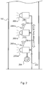
- Fig. 2 shows an internal view of the tower 110 of the wind turbine 100.
- a plurality of lights 200 Internal to the tower 110 are a plurality of lights 200, which are used by a technician during commissioning and/or servicing operations. Although only three lights 200 are depicted, any number of the lights 200 may be located in the tower 110. Moreover, additional lights 200 may be located in the nacelle 120 (not shown).
- Power lines 202 provide power to the lights 200, e.g., in a parallel wiring configuration.
- a wireless lighting control system in the wind turbine 100 includes a switch 204 that is capable of being controlled or manipulated by a technician (i.e., a "locally controllable” switch) to turn on/off one of the lights 200 and one or more remotely controllable switches, each located at a corresponding one of the other lights 200.
- the switch 204 may be hardwired to one of the lights 200-a to control the flow of power to the light 200-a.
- the switch 204 may be in wireless communication with the light 200-a. Whether the coupling is hardwired or wireless, the light 200-a is configured to switch on or off in response to a technician manipulating the switch 204.
- the other lights 200-b, 200-c, remote from the switch 204 are not directly controlled by the switch 204. Rather, a switch-on signal is generated at the light 200-a in response to a switching-on manipulation of the switch 204 and the switch-on signal is wirelessly received by one or more of the remotely controllable switches located at the other lights 200-b, 200-c.
- the remotely controllable switches in turn, switch on power to their associated lights 200.
- a receiver 206-b shown in the figure represents the remotely controllable switch at the light 200-b.
- a receiver 206-c represents the remotely controllable switch at the light 200-c.
- the switch-on signal may be transmitted by a wireless transmitter 208-a located at the light 200-a.
- the wireless transmitter 208-a may be, for example, an infrared or other non-visible light source, an acoustic transmitter (e.g., an ultrasonic transmitter), a radio frequency transmitter, or the like, and may be configured to transmit the switch-on signal in response to the switch 204 being turned on by the technician.
- an acoustic transmitter e.g., an ultrasonic transmitter
- a radio frequency transmitter e.g., a radio frequency transmitter
- a second switch-on signal is generated by a wireless transmitter 208-b located at the light 200-b.
- the second switch-on signal is received by the receiver 206-c, which is part of the remotely controllable switch of the light 200-c and that remotely controllable switch then powers on the light 200-c in the same manner that the light 200-b is powered on in response to receiving the first switch-on signal.
- This daisy-chain arrangement of lights and wireless transmitters and receivers shown in Fig. 2 may be extended so that any number of lights may be powered on in rapid sequence in response to a technician manipulating the switch 204.
- the light 200-c may be within range to receive the first switch-on signal and power on in response thereto, rendering the second switch-on signal redundant at least with respect to the light 200-c.
- redundancies may be of value to compensate for interference or other anomalies that might otherwise disrupt operation of the lighting control system.
- the light 200-a In addition to generating a switch-on signal, the light 200-a generates a switch-off signal.
- the switch-off signal is generated in response to a switch-off manipulation of the switch 204 by a technician.
- the initially produced switch-off signal is wirelessly transmitted to one or more of the remotely controllable switches located at the other lights 200, which in turn cause additional switch-off signals to be generated and propagated to other lights 200. In this manner, all of the lights 200 receive commands to turn off. The lights may later be turned back on again by implementation of the switching on procedures described above.
- the switch 204 may be a first one of multiple switches that have the same or substantially similar function.
- the switch 204 may be located proximate to an access port in the bottom portion of the tower 110 and another switch similar in function to the switch 204 may be located proximate to an access port in the nacelle 120.
- Each switch may be located with one to three meters, for example, of a corresponding access port or sufficiently proximate to the corresponding access port so that the safety of a technician is not likely to be compromised in the process of locating and turning on a switch.
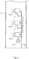
- Fig. 3 shows an alternative embodiment of the wireless lighting control system shown in Fig. 2 .
- the wireless transmitters 208 of the Fig. 2 embodiment are omitted and the switch-on signals are instead transmitted using the visible light generated by the lights 200.
- each of the receivers 206-c which wirelessly receive the switch-on signals, may include a visible light photo-detector to indirectly detect when the switch 204 has been turned on and cause a corresponding one of the lights 200 to turn on.
- no switch-off signals are actively generated.
- each remotely controllable switch is configured to wirelessly sense whether a neighboring light source is switched off using the visible light photo-detector. The remotely controllable switch switches off power to a corresponding light 200 in response to sensing that the neighboring light source is switched off.
- switch-on signal One benefit of using the light generated by the lights 200 as the switch-on signal is the elimination of the wireless switch-on and switch-off signals. Such wireless signals consume power and might, in some circumstances, disrupt operations and communications of other systems in the wind turbine 100. On the other hand the use of switch-on and switch-off signals may be a more reliable and resilient solution than the use of photo-detectors under certain conditions.
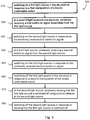
- Fig. 4 shows an example method 400 for switching on/off a plurality of light sources internal to a large structure, such as the wind turbine 100 in Fig. 1 .
- the method 400 may at least partially be implemented by the wireless lighting control system, which includes the locally controllable switch 204 and the remotely controllable switches (represented in Figs. 2 and 3 by the receivers 206).
- the method 400 may be implemented when a person, such as a technician, is accessing the structure and needs to use lighting internal to the structure to carry out a task.
- a first light source in the structure is switched on in response to a first manipulation of a locally controllable switch. For example, a technician may manually move or operate the locally controllable switch to place it in a closed circuit configuration.
- the switch 204 may serve as the locally controllable switch and the light 200-a may serve as the first light source.
- a first switch-on signal is transmitted from the first light source and wirelessly received at a second light source (e.g., the light 200-b) in the structure.
- the second light source is switched on in response to the wirelessly received first switch-on signal.
- the first switch-on signal is received as light from the first light source and a photo-detector at the second light source is used to wirelessly receive the light.
- the first switch-on signal is one of a non-visible light signal, a radio frequency signal, and an acoustic signal emitted from a wireless transmitter located at the first light source.
- a receiver at a third light source wirelessly receives a second switch-on signal from the second light source and, at stage 450, the third light source is switched on in response to the wirelessly received second switch-on signal.
- the method 400 may be modified to repeat stages 420 through 440 any number of times necessary to switch on additional lights.
- a third switch-on signal may be transmitted from the third light source to a wireless receiver located at a fourth light source, thereby causing the fourth light source to turn on. This pattern may be repeated for additional light sources.
- the technician may turn off the lights internal to the structure before leaving. More specifically, at stage 460, the first light source in the structure is turned off in response to a second manipulation of the first locally controllable switch. Then, at stage 470, a switch-off signal is transmitted from the first light source and wirelessly received at the second light source. Finally, at stage 480, the second light source is switched off in response to the wirelessly received switch-off signal. Stages 470 and 480 may be repeated as necessary, mutatis mutandis, to turn off any additional light sources.
- the method 400 is presented as an example method and, in fact, various modifications to the method, in addition to those described above, are contemplated.
- the method 400 may be extended to include similar stages in which a second locally controllable switch is used by a technician to turn the lights on and/or off.
- the method 400 may be adapted for implementation in the wind turbine 100 having a first locally controllable switch located in a bottom portion of the tower and a second locally controllable switch having the same function but located in the nacelle.
- Fig. 5 shows another example method 500 for switching on/off a plurality of light sources internal to a large structure, such as the wind turbine 100 in Fig. 1 .
- the stages 410 through 460 are the same as in the method 400 of Fig. 4 .
- switch-on signals are transmitted using visible light generated by the first and second lights sources. Therefore, instead of receiving a switch-off signal to trigger switching off, the second light source senses that the first light source is switched off using a photo-detector that can detect when ambient light falls below a predetermined threshold. Accordingly, in the method 500, the stages 470 and 480 which pertain to use of the switch-off signal, are omitted and replaced with corresponding stages 570 and 580.
Landscapes
- Engineering & Computer Science (AREA)
- Life Sciences & Earth Sciences (AREA)
- Sustainable Development (AREA)
- Sustainable Energy (AREA)
- Chemical & Material Sciences (AREA)
- Combustion & Propulsion (AREA)
- Mechanical Engineering (AREA)
- General Engineering & Computer Science (AREA)
- Wind Motors (AREA)
Claims (13)
- Verfahren zum Ein- und Ausschalten einer Vielzahl von Lichtquellen innerhalb einer großen Struktur, wobei die Struktur eine Windturbine (100) einschließlich eines Turms (110) und einer Gondel (120) ist, die auf dem Turm montiert und von diesem getragen wird, das Verfahren (400) umfassend:Einschalten einer ersten Lichtquelle (200-a) in der Struktur als Reaktion auf eine erste Manipulation eines ersten lokal regelbaren Schalters (410), wobei der erste lokal regelbare Schalter in mindestens einem von einem unteren Teil des Turms (110) und in der Gondel (120) angeordnet ist;drahtloses Empfangen eines ersten Einschaltsignals an einer zweiten Lichtquelle in der Struktur, das von der ersten Lichtquelle (420) gesendet wird; undEinschalten der zweiten Lichtquelle (200-b) als Reaktion auf das drahtlos empfangene erste Einschaltsignal (430).
- Verfahren nach Anspruch 1, wobei das erste Einschaltsignal als Licht von der ersten Lichtquelle empfangen wird und ein Fotodetektor an der zweiten Lichtquelle verwendet wird, um das Licht drahtlos zu empfangen.
- Verfahren nach Anspruch 1, wobei das erste Einschaltsignal eines von einem nicht sichtbaren Lichtsignal, einem Hochfrequenzsignal und einem akustischen Signal ist, das von einem drahtlosen Sender emittiert wird, der an der ersten Lichtquelle angeordnet ist.
- Verfahren nach Anspruch 1, weiterhin umfassend:an einer dritten Lichtquelle, drahtloses Empfangen eines zweiten Einschaltsignals von der zweiten Lichtquelle (440); undEinschalten der dritten Lichtquelle als Reaktion auf das drahtlos empfangene zweite Einschaltsignal (450).
- Verfahren nach Anspruch 1, weiterhin umfassend:Ausschalten der ersten Lichtquelle in der Struktur als Reaktion auf eine zweite Manipulation des ersten lokal regelbaren Schalters (460);drahtloses Empfangen eines von der ersten Lichtquelle (470) gesendeten Ausschaltsignals an der zweiten Lichtquelle; undAusschalten der zweiten Lichtquelle als Reaktion auf das drahtlos empfangene Ausschaltsignal (480).
- Verfahren nach Anspruch 1, weiterhin umfassend:Ausschalten der ersten Lichtquelle in der Struktur als Reaktion auf eine zweite Manipulation des ersten lokal regelbaren Schalters (560);drahtloses Erfassen an der zweiten Lichtquelle, dass die erste Lichtquelle unter Verwendung eines Fotodetektors an der zweiten Lichtquelle (570) ausgeschaltet ist; undAusschalten der zweiten Lichtquelle als Reaktion auf das Erfassen, dass die erste Lichtquelle ausgeschaltet ist (580).
- Verfahren nach Anspruch 1, weiterhin umfassend:Einschalten einer dritten Lichtquelle in der Struktur als Reaktion auf eine Manipulation eines zweiten lokal regelbaren Schalters;drahtloses Empfangen eines Einschaltsignals an einer vierten Lichtquelle in der Struktur, das von der dritten Lichtquelle gesendet wird; undEinschalten der vierten Lichtquelle als Reaktion auf das von der dritten Lichtquelle drahtlos empfangene Einschaltsignal.
- Windturbine (100), umfassend:einen Turm (110), der eine erste Zugangsöffnung für Techniker aufweist;eine Gondel (120), die an dem Turm montiert ist und von diesem getragen wird und eine zweite Zugangsöffnung für Techniker aufweist;eine Vielzahl von Lichtquellen (200), die innerhalb des Turms (110) und der Gondel (120) montiert sind; undein drahtloses Beleuchtungsregelungssystem, wobei das drahtlose Beleuchtungsregelsystem Folgendes umfasst:einen ersten lokal regelbaren Schalter (204) zur Regelung der Leistung an die Vielzahl von Lichtquellen, wobei der erste lokal regelbare Lichtschalter in der Nähe der ersten Zugangsöffnung angeordnet ist;einen zweiten lokal regelbaren Schalter (204) zur Regelung der Leistung an die Vielzahl von Lichtquellen, wobei der zweite lokal regelbare Lichtschalter in der Nähe der zweiten Zugangsöffnung angeordnet ist; undeinen fernregelbaren Lichtschalter, der an jeder von einer oder mehreren der Lichtquellen angeordnet ist, wobei der fernregelbare Schalter konfiguriert ist zum:drahtlosen Empfangen (206) eines Einschaltsignals, das als Reaktion auf eine Manipulation von mindestens einem der ersten und zweiten lokal regelbaren Schalter (204) erzeugt wird; undEinschalten von Leistung an die entsprechende Lichtquelle als Reaktion auf das Empfangen des Einschaltsignals.
- Windturbine (100) nach Anspruch 8, wobei mindestens einer der ersten und zweiten lokal regelbaren Schalter (204) einen drahtlosen Sender (208) einschließt, der konfiguriert ist, um das Einschaltsignal als Reaktion auf eine Manipulation des mindestens einen der ersten und zweiten lokal regelbaren Schalter (204) zu erzeugen und zu senden, und wobei der drahtlose Sender (208) eine von einer sichtbaren Lichtquelle, einer nicht sichtbaren Lichtquelle, einem akustischen Sender und einem Hochfrequenzsender ist.
- Windturbine (100) nach Anspruch 9, wobei das drahtlose Beleuchtungsregelungssystem weiterhin einen drahtlosen Sender (208) umfasst, der an jeder von einer oder mehreren der Lichtquellen (200) angeordnet ist, wobei das Einschaltsignal ein erstes Einschaltsignal ist, wobei der drahtlose Sender (208) konfiguriert ist, um ein zweites Einschaltsignal als mindestens eines von einem optischen Signal eines nicht sichtbaren Lichts, einem Hochfrequenzsignal und einem akustischen Signal zu erzeugen, und wobei der fernregelbare Schalter, der an jeder von einer oder mehreren der Lichtquellen angeordnet ist, zum drahtlosen Empfangen (206) der ersten und/oder zweiten Einschaltsignale und zum Einschalten der Leistung an die entsprechende Lichtquelle als Reaktion auf das Empfangen des ersten und/oder zweiten Einschaltsignals konfiguriert ist.
- Windturbine (100) nach Anspruch 10, wobei der drahtlose Sender (208) des mindestens einen der ersten und zweiten lokal regelbaren Schalter (204) weiterhin dazu konfiguriert ist, ein erstes Ausschaltsignal zu erzeugen und zu senden, wobei der drahtlose Sender (208), der an jeder von einer oder mehreren der Lichtquellen (200) angeordnet ist, weiterhin konfiguriert ist, um ein zweites Ausschaltsignal als mindestens eines von einem optischen Signal eines nicht sichtbaren Lichts, einem Hochfrequenzsignal, und einem akustischen Signal zu erzeugen und wobei der fernregelbare Schalter, der an jeder von einer oder mehreren der Lichtquellen angeordnet ist, zum drahtlosen Empfangen (206) der ersten und/oder zweiten Ausschaltsignale und zum Ausschalten der Leistung an die entsprechende Lichtquelle als Reaktion auf das Empfangen des ersten und/oder zweiten Ausschaltsignals konfiguriert ist.
- Windturbine (100) nach Anspruch 9, wobei das Einschaltsignal ein erstes Einschaltsignal eines sichtbaren Lichts ist, wobei das von mindestens einer der mehreren Lichtquellen (200) erzeugte sichtbare Licht ein zweites sichtbares Lichteinschaltsignal ist, und wobei der fernregelbare Schalter, der an jeder der einen oder mehreren Lichtquellen angeordnet ist, zum drahtlosen Empfangen (206) der ersten und/oder zweiten Einschaltsignale eines sichtbaren Lichts unter Verwendung eines Fotodetektors für sichtbares Licht und zum Einschalten der Leistung an die entsprechende Lichtquelle (200) als Reaktion auf das Empfangen des ersten und/oder zweiten Einschaltsignals konfiguriert ist.
- Windturbine (100) nach Anspruch 12, wobei der fernregelbare Schalter weiterhin konfiguriert ist, um unter Verwendung des Fotodetektors für sichtbares Licht drahtlos zu erfassen, ob eine benachbarte Lichtquelle ausgeschaltet ist, und um Leistung an die entsprechende Lichtquelle als Reaktion auf das Erfassen, dass die benachbarte Lichtquelle ausgeschaltet ist, auszuschalten.
Applications Claiming Priority (2)
| Application Number | Priority Date | Filing Date | Title |
|---|---|---|---|
| US201261657780P | 2012-06-09 | 2012-06-09 | |
| PCT/DK2013/050177 WO2013182203A2 (en) | 2012-06-09 | 2013-06-07 | Wireless lighting control system for a wind turbine |
Publications (2)
| Publication Number | Publication Date |
|---|---|
| EP2859232A2 EP2859232A2 (de) | 2015-04-15 |
| EP2859232B1 true EP2859232B1 (de) | 2018-08-15 |
Family
ID=48700237
Family Applications (1)
| Application Number | Title | Priority Date | Filing Date |
|---|---|---|---|
| EP13732084.2A Active EP2859232B1 (de) | 2012-06-09 | 2013-06-07 | Drahtloses beleuchtungsregelungssystem für eine windkraftanlage |
Country Status (4)
| Country | Link |
|---|---|
| US (1) | US9408281B2 (de) |
| EP (1) | EP2859232B1 (de) |
| ES (1) | ES2687052T3 (de) |
| WO (1) | WO2013182203A2 (de) |
Families Citing this family (1)
| Publication number | Priority date | Publication date | Assignee | Title |
|---|---|---|---|---|
| ES2724773A1 (es) * | 2018-03-08 | 2019-09-16 | Saprem Electronica S L | Dispositivo y luminaria para iluminar las escaleras y otros espacios de los aerogeneradores. |
Family Cites Families (4)
| Publication number | Priority date | Publication date | Assignee | Title |
|---|---|---|---|---|
| DE102006058147A1 (de) | 2006-12-09 | 2008-06-26 | Dieter Sobottka | Verfahren und Funksteueranlage zum Schalten einer Straßenbeleuchtungsanlage |
| DE102008062674B3 (de) | 2008-12-17 | 2010-06-17 | Osram Gesellschaft mit beschränkter Haftung | Verfahren zum Steuern des Abstrahlverhaltens von Leuchten in einer Anordnung aus einer Mehrzahl von Leuchten sowie Anordnung aus Mehrzahl von Leuchten |
| US8449255B2 (en) * | 2010-03-21 | 2013-05-28 | Btpatent Llc | Wind turbine blade system with air passageway |
| US8511177B1 (en) * | 2011-12-15 | 2013-08-20 | Shaw Shahriar Makaremi | Blade condition monitoring system |
-
2013
- 2013-06-07 US US14/403,870 patent/US9408281B2/en active Active
- 2013-06-07 EP EP13732084.2A patent/EP2859232B1/de active Active
- 2013-06-07 ES ES13732084.2T patent/ES2687052T3/es active Active
- 2013-06-07 WO PCT/DK2013/050177 patent/WO2013182203A2/en not_active Ceased
Non-Patent Citations (1)
| Title |
|---|
| None * |
Also Published As
| Publication number | Publication date |
|---|---|
| EP2859232A2 (de) | 2015-04-15 |
| ES2687052T3 (es) | 2018-10-23 |
| US9408281B2 (en) | 2016-08-02 |
| WO2013182203A3 (en) | 2014-04-17 |
| US20150137702A1 (en) | 2015-05-21 |
| WO2013182203A2 (en) | 2013-12-12 |
Similar Documents
| Publication | Publication Date | Title |
|---|---|---|
| AU2004209032B2 (en) | Method for mounting rotor blades and rotor blade for a wind turbine | |
| US20110193344A1 (en) | Control Network for Wind Turbine Park | |
| EP2177755A2 (de) | Verfahren und System zum Betrieb eines Windturbinengenerators | |
| KR20130026490A (ko) | 수직축 풍력 발전기 | |
| CN101576050B (zh) | 具有无线倾斜控制的风力涡轮机 | |
| CA2840441A1 (en) | Method and apparatus for wind turbine noise reduction | |
| KR102089562B1 (ko) | 드론을 이용한 풍력발전기 점검방법 | |
| CN102803715A (zh) | 用于风力涡轮发电机的手持终端、风力涡轮发电机和风力站 | |
| US20150308406A1 (en) | Wind turbine shadow flicker protection system | |
| SE1550020A1 (sv) | Wind turbine, wind farm, and method for generating energy | |
| CN108386316B (zh) | 风力发电机组降噪系统和方法、控制装置及其存储介质 | |
| EP2788620B1 (de) | Verfahren und systeme zur warnung eines windturbinengenerators in einem windpark vor einem extremen windereignis | |
| US20140367968A1 (en) | Device and method for protecting a wind generator in the event of violent winds and wind generator provided with such a device | |
| US11955925B2 (en) | Large-scale solar tracker installation control system | |
| KR20160019034A (ko) | 기동성 해상 풍력 터빈 | |
| US9408281B2 (en) | Wireless lightning control system for a wind turbine | |
| US7437216B2 (en) | Method for controlling a wind energy turbine of a wind park comprising multiple wind energy turbines | |
| ES2763074T3 (es) | Control para una turbina eólica | |
| US20140217729A1 (en) | Remote sensing system for wind turbines | |
| DK2976525T3 (en) | TURBINE, TURBINE CONTROL UNIT AND OPERATING PROCEDURE | |
| CN206607947U (zh) | 一种新型风光互补通讯基站 | |
| KR101169225B1 (ko) | 수평 양력형 수직 축 풍력발전기 | |
| EP2837819B1 (de) | Verfahren zum Einbauen eines Rotorblatts | |
| CN107035617B (zh) | 用于升级多厂商风力涡轮的系统和方法 | |
| KR20180096987A (ko) | 원격제어 가능한 물순환장치 |
Legal Events
| Date | Code | Title | Description |
|---|---|---|---|
| PUAI | Public reference made under article 153(3) epc to a published international application that has entered the european phase |
Free format text: ORIGINAL CODE: 0009012 |
|
| 17P | Request for examination filed |
Effective date: 20150105 |
|
| AK | Designated contracting states |
Kind code of ref document: A2 Designated state(s): AL AT BE BG CH CY CZ DE DK EE ES FI FR GB GR HR HU IE IS IT LI LT LU LV MC MK MT NL NO PL PT RO RS SE SI SK SM TR |
|
| AX | Request for extension of the european patent |
Extension state: BA ME |
|
| RAP1 | Party data changed (applicant data changed or rights of an application transferred) |
Owner name: VESTAS WIND SYSTEMS A/S |
|
| DAX | Request for extension of the european patent (deleted) | ||
| REG | Reference to a national code |
Ref country code: DE Ref legal event code: R079 Ref document number: 602013042018 Country of ref document: DE Free format text: PREVIOUS MAIN CLASS: F03D0011000000 Ipc: F03D0080000000 |
|
| RIC1 | Information provided on ipc code assigned before grant |
Ipc: F03D 80/00 20160101AFI20180126BHEP |
|
| GRAP | Despatch of communication of intention to grant a patent |
Free format text: ORIGINAL CODE: EPIDOSNIGR1 |
|
| STAA | Information on the status of an ep patent application or granted ep patent |
Free format text: STATUS: GRANT OF PATENT IS INTENDED |
|
| INTG | Intention to grant announced |
Effective date: 20180316 |
|
| RIN1 | Information on inventor provided before grant (corrected) |
Inventor name: ROSENVARD, PAW Inventor name: JENSEN, CARSTEN LINDGAARD Inventor name: LUCENTE, MICHELE Inventor name: RASMUSSEN, PETER |
|
| GRAS | Grant fee paid |
Free format text: ORIGINAL CODE: EPIDOSNIGR3 |
|
| GRAA | (expected) grant |
Free format text: ORIGINAL CODE: 0009210 |
|
| STAA | Information on the status of an ep patent application or granted ep patent |
Free format text: STATUS: THE PATENT HAS BEEN GRANTED |
|
| AK | Designated contracting states |
Kind code of ref document: B1 Designated state(s): AL AT BE BG CH CY CZ DE DK EE ES FI FR GB GR HR HU IE IS IT LI LT LU LV MC MK MT NL NO PL PT RO RS SE SI SK SM TR |
|
| REG | Reference to a national code |
Ref country code: CH Ref legal event code: EP Ref country code: GB Ref legal event code: FG4D Ref country code: AT Ref legal event code: REF Ref document number: 1030083 Country of ref document: AT Kind code of ref document: T Effective date: 20180815 |
|
| REG | Reference to a national code |
Ref country code: IE Ref legal event code: FG4D |
|
| REG | Reference to a national code |
Ref country code: DE Ref legal event code: R096 Ref document number: 602013042018 Country of ref document: DE |
|
| REG | Reference to a national code |
Ref country code: ES Ref legal event code: FG2A Ref document number: 2687052 Country of ref document: ES Kind code of ref document: T3 Effective date: 20181023 |
|
| REG | Reference to a national code |
Ref country code: NL Ref legal event code: MP Effective date: 20180815 |
|
| REG | Reference to a national code |
Ref country code: LT Ref legal event code: MG4D |
|
| REG | Reference to a national code |
Ref country code: AT Ref legal event code: MK05 Ref document number: 1030083 Country of ref document: AT Kind code of ref document: T Effective date: 20180815 |
|
| PG25 | Lapsed in a contracting state [announced via postgrant information from national office to epo] |
Ref country code: FI Free format text: LAPSE BECAUSE OF FAILURE TO SUBMIT A TRANSLATION OF THE DESCRIPTION OR TO PAY THE FEE WITHIN THE PRESCRIBED TIME-LIMIT Effective date: 20180815 Ref country code: LT Free format text: LAPSE BECAUSE OF FAILURE TO SUBMIT A TRANSLATION OF THE DESCRIPTION OR TO PAY THE FEE WITHIN THE PRESCRIBED TIME-LIMIT Effective date: 20180815 Ref country code: AT Free format text: LAPSE BECAUSE OF FAILURE TO SUBMIT A TRANSLATION OF THE DESCRIPTION OR TO PAY THE FEE WITHIN THE PRESCRIBED TIME-LIMIT Effective date: 20180815 Ref country code: IS Free format text: LAPSE BECAUSE OF FAILURE TO SUBMIT A TRANSLATION OF THE DESCRIPTION OR TO PAY THE FEE WITHIN THE PRESCRIBED TIME-LIMIT Effective date: 20181215 Ref country code: RS Free format text: LAPSE BECAUSE OF FAILURE TO SUBMIT A TRANSLATION OF THE DESCRIPTION OR TO PAY THE FEE WITHIN THE PRESCRIBED TIME-LIMIT Effective date: 20180815 Ref country code: GR Free format text: LAPSE BECAUSE OF FAILURE TO SUBMIT A TRANSLATION OF THE DESCRIPTION OR TO PAY THE FEE WITHIN THE PRESCRIBED TIME-LIMIT Effective date: 20181116 Ref country code: NO Free format text: LAPSE BECAUSE OF FAILURE TO SUBMIT A TRANSLATION OF THE DESCRIPTION OR TO PAY THE FEE WITHIN THE PRESCRIBED TIME-LIMIT Effective date: 20181115 Ref country code: BG Free format text: LAPSE BECAUSE OF FAILURE TO SUBMIT A TRANSLATION OF THE DESCRIPTION OR TO PAY THE FEE WITHIN THE PRESCRIBED TIME-LIMIT Effective date: 20181115 Ref country code: SE Free format text: LAPSE BECAUSE OF FAILURE TO SUBMIT A TRANSLATION OF THE DESCRIPTION OR TO PAY THE FEE WITHIN THE PRESCRIBED TIME-LIMIT Effective date: 20180815 Ref country code: NL Free format text: LAPSE BECAUSE OF FAILURE TO SUBMIT A TRANSLATION OF THE DESCRIPTION OR TO PAY THE FEE WITHIN THE PRESCRIBED TIME-LIMIT Effective date: 20180815 |
|
| PG25 | Lapsed in a contracting state [announced via postgrant information from national office to epo] |
Ref country code: HR Free format text: LAPSE BECAUSE OF FAILURE TO SUBMIT A TRANSLATION OF THE DESCRIPTION OR TO PAY THE FEE WITHIN THE PRESCRIBED TIME-LIMIT Effective date: 20180815 Ref country code: LV Free format text: LAPSE BECAUSE OF FAILURE TO SUBMIT A TRANSLATION OF THE DESCRIPTION OR TO PAY THE FEE WITHIN THE PRESCRIBED TIME-LIMIT Effective date: 20180815 Ref country code: AL Free format text: LAPSE BECAUSE OF FAILURE TO SUBMIT A TRANSLATION OF THE DESCRIPTION OR TO PAY THE FEE WITHIN THE PRESCRIBED TIME-LIMIT Effective date: 20180815 |
|
| PG25 | Lapsed in a contracting state [announced via postgrant information from national office to epo] |
Ref country code: RO Free format text: LAPSE BECAUSE OF FAILURE TO SUBMIT A TRANSLATION OF THE DESCRIPTION OR TO PAY THE FEE WITHIN THE PRESCRIBED TIME-LIMIT Effective date: 20180815 Ref country code: CZ Free format text: LAPSE BECAUSE OF FAILURE TO SUBMIT A TRANSLATION OF THE DESCRIPTION OR TO PAY THE FEE WITHIN THE PRESCRIBED TIME-LIMIT Effective date: 20180815 Ref country code: PL Free format text: LAPSE BECAUSE OF FAILURE TO SUBMIT A TRANSLATION OF THE DESCRIPTION OR TO PAY THE FEE WITHIN THE PRESCRIBED TIME-LIMIT Effective date: 20180815 Ref country code: IT Free format text: LAPSE BECAUSE OF FAILURE TO SUBMIT A TRANSLATION OF THE DESCRIPTION OR TO PAY THE FEE WITHIN THE PRESCRIBED TIME-LIMIT Effective date: 20180815 Ref country code: EE Free format text: LAPSE BECAUSE OF FAILURE TO SUBMIT A TRANSLATION OF THE DESCRIPTION OR TO PAY THE FEE WITHIN THE PRESCRIBED TIME-LIMIT Effective date: 20180815 |
|
| REG | Reference to a national code |
Ref country code: DE Ref legal event code: R097 Ref document number: 602013042018 Country of ref document: DE |
|
| PG25 | Lapsed in a contracting state [announced via postgrant information from national office to epo] |
Ref country code: DK Free format text: LAPSE BECAUSE OF FAILURE TO SUBMIT A TRANSLATION OF THE DESCRIPTION OR TO PAY THE FEE WITHIN THE PRESCRIBED TIME-LIMIT Effective date: 20180815 Ref country code: SM Free format text: LAPSE BECAUSE OF FAILURE TO SUBMIT A TRANSLATION OF THE DESCRIPTION OR TO PAY THE FEE WITHIN THE PRESCRIBED TIME-LIMIT Effective date: 20180815 Ref country code: SK Free format text: LAPSE BECAUSE OF FAILURE TO SUBMIT A TRANSLATION OF THE DESCRIPTION OR TO PAY THE FEE WITHIN THE PRESCRIBED TIME-LIMIT Effective date: 20180815 |
|
| PLBE | No opposition filed within time limit |
Free format text: ORIGINAL CODE: 0009261 |
|
| STAA | Information on the status of an ep patent application or granted ep patent |
Free format text: STATUS: NO OPPOSITION FILED WITHIN TIME LIMIT |
|
| 26N | No opposition filed |
Effective date: 20190516 |
|
| PG25 | Lapsed in a contracting state [announced via postgrant information from national office to epo] |
Ref country code: SI Free format text: LAPSE BECAUSE OF FAILURE TO SUBMIT A TRANSLATION OF THE DESCRIPTION OR TO PAY THE FEE WITHIN THE PRESCRIBED TIME-LIMIT Effective date: 20180815 |
|
| PG25 | Lapsed in a contracting state [announced via postgrant information from national office to epo] |
Ref country code: MC Free format text: LAPSE BECAUSE OF FAILURE TO SUBMIT A TRANSLATION OF THE DESCRIPTION OR TO PAY THE FEE WITHIN THE PRESCRIBED TIME-LIMIT Effective date: 20180815 |
|
| REG | Reference to a national code |
Ref country code: CH Ref legal event code: PL |
|
| REG | Reference to a national code |
Ref country code: BE Ref legal event code: MM Effective date: 20190630 |
|
| PG25 | Lapsed in a contracting state [announced via postgrant information from national office to epo] |
Ref country code: TR Free format text: LAPSE BECAUSE OF FAILURE TO SUBMIT A TRANSLATION OF THE DESCRIPTION OR TO PAY THE FEE WITHIN THE PRESCRIBED TIME-LIMIT Effective date: 20180815 |
|
| PG25 | Lapsed in a contracting state [announced via postgrant information from national office to epo] |
Ref country code: IE Free format text: LAPSE BECAUSE OF NON-PAYMENT OF DUE FEES Effective date: 20190607 |
|
| PG25 | Lapsed in a contracting state [announced via postgrant information from national office to epo] |
Ref country code: BE Free format text: LAPSE BECAUSE OF NON-PAYMENT OF DUE FEES Effective date: 20190630 Ref country code: LU Free format text: LAPSE BECAUSE OF NON-PAYMENT OF DUE FEES Effective date: 20190607 Ref country code: CH Free format text: LAPSE BECAUSE OF NON-PAYMENT OF DUE FEES Effective date: 20190630 Ref country code: LI Free format text: LAPSE BECAUSE OF NON-PAYMENT OF DUE FEES Effective date: 20190630 |
|
| PG25 | Lapsed in a contracting state [announced via postgrant information from national office to epo] |
Ref country code: PT Free format text: LAPSE BECAUSE OF FAILURE TO SUBMIT A TRANSLATION OF THE DESCRIPTION OR TO PAY THE FEE WITHIN THE PRESCRIBED TIME-LIMIT Effective date: 20181215 |
|
| PG25 | Lapsed in a contracting state [announced via postgrant information from national office to epo] |
Ref country code: CY Free format text: LAPSE BECAUSE OF FAILURE TO SUBMIT A TRANSLATION OF THE DESCRIPTION OR TO PAY THE FEE WITHIN THE PRESCRIBED TIME-LIMIT Effective date: 20180815 |
|
| PG25 | Lapsed in a contracting state [announced via postgrant information from national office to epo] |
Ref country code: MT Free format text: LAPSE BECAUSE OF FAILURE TO SUBMIT A TRANSLATION OF THE DESCRIPTION OR TO PAY THE FEE WITHIN THE PRESCRIBED TIME-LIMIT Effective date: 20180815 Ref country code: HU Free format text: LAPSE BECAUSE OF FAILURE TO SUBMIT A TRANSLATION OF THE DESCRIPTION OR TO PAY THE FEE WITHIN THE PRESCRIBED TIME-LIMIT; INVALID AB INITIO Effective date: 20130607 |
|
| PG25 | Lapsed in a contracting state [announced via postgrant information from national office to epo] |
Ref country code: MK Free format text: LAPSE BECAUSE OF FAILURE TO SUBMIT A TRANSLATION OF THE DESCRIPTION OR TO PAY THE FEE WITHIN THE PRESCRIBED TIME-LIMIT Effective date: 20180815 |
|
| P01 | Opt-out of the competence of the unified patent court (upc) registered |
Effective date: 20230521 |
|
| PGFP | Annual fee paid to national office [announced via postgrant information from national office to epo] |
Ref country code: DE Payment date: 20250626 Year of fee payment: 13 |
|
| PGFP | Annual fee paid to national office [announced via postgrant information from national office to epo] |
Ref country code: GB Payment date: 20250617 Year of fee payment: 13 |
|
| PGFP | Annual fee paid to national office [announced via postgrant information from national office to epo] |
Ref country code: FR Payment date: 20250624 Year of fee payment: 13 |
|
| PGFP | Annual fee paid to national office [announced via postgrant information from national office to epo] |
Ref country code: ES Payment date: 20250710 Year of fee payment: 13 |