EP2859162B1 - Electromechanical lock - Google Patents
Electromechanical lock Download PDFInfo
- Publication number
- EP2859162B1 EP2859162B1 EP13727911.3A EP13727911A EP2859162B1 EP 2859162 B1 EP2859162 B1 EP 2859162B1 EP 13727911 A EP13727911 A EP 13727911A EP 2859162 B1 EP2859162 B1 EP 2859162B1
- Authority
- EP
- European Patent Office
- Prior art keywords
- lever
- control component
- locked state
- passage
- returns
- Prior art date
- Legal status (The legal status is an assumption and is not a legal conclusion. Google has not performed a legal analysis and makes no representation as to the accuracy of the status listed.)
- Active
Links
Images


Classifications
-
- E—FIXED CONSTRUCTIONS
- E05—LOCKS; KEYS; WINDOW OR DOOR FITTINGS; SAFES
- E05B—LOCKS; ACCESSORIES THEREFOR; HANDCUFFS
- E05B49/00—Electric permutation locks; Circuits therefor ; Mechanical aspects of electronic locks; Mechanical keys therefor
- E05B49/002—Keys with mechanical characteristics, e.g. notches, perforations, opaque marks
- E05B49/004—Keys with mechanical characteristics, e.g. notches, perforations, opaque marks actuating mechanical switches
-
- E—FIXED CONSTRUCTIONS
- E05—LOCKS; KEYS; WINDOW OR DOOR FITTINGS; SAFES
- E05B—LOCKS; ACCESSORIES THEREFOR; HANDCUFFS
- E05B15/00—Other details of locks; Parts for engagement by bolts of fastening devices
- E05B15/04—Spring arrangements in locks
-
- E—FIXED CONSTRUCTIONS
- E05—LOCKS; KEYS; WINDOW OR DOOR FITTINGS; SAFES
- E05B—LOCKS; ACCESSORIES THEREFOR; HANDCUFFS
- E05B47/00—Operating or controlling locks or other fastening devices by electric or magnetic means
- E05B47/0001—Operating or controlling locks or other fastening devices by electric or magnetic means with electric actuators; Constructional features thereof
-
- E—FIXED CONSTRUCTIONS
- E05—LOCKS; KEYS; WINDOW OR DOOR FITTINGS; SAFES
- E05B—LOCKS; ACCESSORIES THEREFOR; HANDCUFFS
- E05B47/00—Operating or controlling locks or other fastening devices by electric or magnetic means
- E05B47/06—Controlling mechanically-operated bolts by electro-magnetically-operated detents
- E05B47/0607—Controlling mechanically-operated bolts by electro-magnetically-operated detents the detent moving pivotally or rotatively
-
- E—FIXED CONSTRUCTIONS
- E05—LOCKS; KEYS; WINDOW OR DOOR FITTINGS; SAFES
- E05B—LOCKS; ACCESSORIES THEREFOR; HANDCUFFS
- E05B47/00—Operating or controlling locks or other fastening devices by electric or magnetic means
- E05B47/06—Controlling mechanically-operated bolts by electro-magnetically-operated detents
- E05B47/0611—Cylinder locks with electromagnetic control
- E05B47/0619—Cylinder locks with electromagnetic control by blocking the rotor
- E05B47/0626—Cylinder locks with electromagnetic control by blocking the rotor radially
- E05B47/063—Cylinder locks with electromagnetic control by blocking the rotor radially with a rectilinearly moveable blocking element
-
- E—FIXED CONSTRUCTIONS
- E05—LOCKS; KEYS; WINDOW OR DOOR FITTINGS; SAFES
- E05B—LOCKS; ACCESSORIES THEREFOR; HANDCUFFS
- E05B15/00—Other details of locks; Parts for engagement by bolts of fastening devices
- E05B15/04—Spring arrangements in locks
- E05B2015/0403—Wound springs
- E05B2015/0406—Wound springs wound in a cylindrical shape
- E05B2015/041—Wound springs wound in a cylindrical shape loaded perpendicular to cylinder axis
-
- E—FIXED CONSTRUCTIONS
- E05—LOCKS; KEYS; WINDOW OR DOOR FITTINGS; SAFES
- E05B—LOCKS; ACCESSORIES THEREFOR; HANDCUFFS
- E05B15/00—Other details of locks; Parts for engagement by bolts of fastening devices
- E05B15/04—Spring arrangements in locks
- E05B2015/0468—Spring arrangements in locks made of one piece with a lock part
-
- E—FIXED CONSTRUCTIONS
- E05—LOCKS; KEYS; WINDOW OR DOOR FITTINGS; SAFES
- E05B—LOCKS; ACCESSORIES THEREFOR; HANDCUFFS
- E05B15/00—Other details of locks; Parts for engagement by bolts of fastening devices
- E05B15/04—Spring arrangements in locks
- E05B2015/0472—Made of rubber, plastics or the like
-
- E—FIXED CONSTRUCTIONS
- E05—LOCKS; KEYS; WINDOW OR DOOR FITTINGS; SAFES
- E05B—LOCKS; ACCESSORIES THEREFOR; HANDCUFFS
- E05B15/00—Other details of locks; Parts for engagement by bolts of fastening devices
- E05B15/04—Spring arrangements in locks
- E05B2015/0496—Springs actuated by cams or the like
-
- E—FIXED CONSTRUCTIONS
- E05—LOCKS; KEYS; WINDOW OR DOOR FITTINGS; SAFES
- E05B—LOCKS; ACCESSORIES THEREFOR; HANDCUFFS
- E05B47/00—Operating or controlling locks or other fastening devices by electric or magnetic means
- E05B2047/0048—Circuits, feeding, monitoring
- E05B2047/0057—Feeding
-
- E—FIXED CONSTRUCTIONS
- E05—LOCKS; KEYS; WINDOW OR DOOR FITTINGS; SAFES
- E05B—LOCKS; ACCESSORIES THEREFOR; HANDCUFFS
- E05B47/00—Operating or controlling locks or other fastening devices by electric or magnetic means
- E05B2047/0048—Circuits, feeding, monitoring
- E05B2047/0057—Feeding
- E05B2047/0062—Feeding by generator
-
- E—FIXED CONSTRUCTIONS
- E05—LOCKS; KEYS; WINDOW OR DOOR FITTINGS; SAFES
- E05B—LOCKS; ACCESSORIES THEREFOR; HANDCUFFS
- E05B47/00—Operating or controlling locks or other fastening devices by electric or magnetic means
- E05B2047/0048—Circuits, feeding, monitoring
- E05B2047/0057—Feeding
- E05B2047/0064—Feeding by solar cells
-
- E—FIXED CONSTRUCTIONS
- E05—LOCKS; KEYS; WINDOW OR DOOR FITTINGS; SAFES
- E05B—LOCKS; ACCESSORIES THEREFOR; HANDCUFFS
- E05B47/00—Operating or controlling locks or other fastening devices by electric or magnetic means
- E05B2047/0048—Circuits, feeding, monitoring
- E05B2047/0065—Saving energy
-
- E—FIXED CONSTRUCTIONS
- E05—LOCKS; KEYS; WINDOW OR DOOR FITTINGS; SAFES
- E05B—LOCKS; ACCESSORIES THEREFOR; HANDCUFFS
- E05B47/00—Operating or controlling locks or other fastening devices by electric or magnetic means
- E05B2047/0094—Mechanical aspects of remotely controlled locks
- E05B2047/0095—Mechanical aspects of locks controlled by telephone signals, e.g. by mobile phones
-
- Y—GENERAL TAGGING OF NEW TECHNOLOGICAL DEVELOPMENTS; GENERAL TAGGING OF CROSS-SECTIONAL TECHNOLOGIES SPANNING OVER SEVERAL SECTIONS OF THE IPC; TECHNICAL SUBJECTS COVERED BY FORMER USPC CROSS-REFERENCE ART COLLECTIONS [XRACs] AND DIGESTS
- Y10—TECHNICAL SUBJECTS COVERED BY FORMER USPC
- Y10T—TECHNICAL SUBJECTS COVERED BY FORMER US CLASSIFICATION
- Y10T70/00—Locks
- Y10T70/70—Operating mechanism
- Y10T70/7051—Using a powered device [e.g., motor]
- Y10T70/7062—Electrical type [e.g., solenoid]
- Y10T70/7068—Actuated after correct combination recognized [e.g., numerical, alphabetical, or magnet[s] pattern]
- Y10T70/7073—Including use of a key
-
- Y—GENERAL TAGGING OF NEW TECHNOLOGICAL DEVELOPMENTS; GENERAL TAGGING OF CROSS-SECTIONAL TECHNOLOGIES SPANNING OVER SEVERAL SECTIONS OF THE IPC; TECHNICAL SUBJECTS COVERED BY FORMER USPC CROSS-REFERENCE ART COLLECTIONS [XRACs] AND DIGESTS
- Y10—TECHNICAL SUBJECTS COVERED BY FORMER USPC
- Y10T—TECHNICAL SUBJECTS COVERED BY FORMER US CLASSIFICATION
- Y10T70/00—Locks
- Y10T70/70—Operating mechanism
- Y10T70/7051—Using a powered device [e.g., motor]
- Y10T70/7062—Electrical type [e.g., solenoid]
- Y10T70/7102—And details of blocking system [e.g., linkage, latch, pawl, spring]
-
- Y—GENERAL TAGGING OF NEW TECHNOLOGICAL DEVELOPMENTS; GENERAL TAGGING OF CROSS-SECTIONAL TECHNOLOGIES SPANNING OVER SEVERAL SECTIONS OF THE IPC; TECHNICAL SUBJECTS COVERED BY FORMER USPC CROSS-REFERENCE ART COLLECTIONS [XRACs] AND DIGESTS
- Y10—TECHNICAL SUBJECTS COVERED BY FORMER USPC
- Y10T—TECHNICAL SUBJECTS COVERED BY FORMER US CLASSIFICATION
- Y10T70/00—Locks
- Y10T70/70—Operating mechanism
- Y10T70/7051—Using a powered device [e.g., motor]
- Y10T70/7062—Electrical type [e.g., solenoid]
- Y10T70/7136—Key initiated actuation of device
Definitions
- the invention relates to an electromechanical lock.
- Electromechanical locks are replacing the traditional mechanical locks. Further refinement is needed for making the electromechanical lock to consume as little electric power as possible and managing the various states of the electromechanical lock, such as the return of the electromechanical lock to the locked state.
- EP 2248971 deemed as the closest prior art, discloses an electronic lock.
- the present invention seeks to provide an improved electromechanical lock.
- an electromechanical lock as specified in claim 1.
- the Applicant has invented many improvements for the electromechanical locks, such as those disclosed in EP applications 05112272.9 , 07112677.5 , 07112676.7 , 07112673.4 , 09180117.5 , and 12171614.6 , for example. A complete discussion of all those details is not repeated here, but the reader is advised to consult those applications.
- Figure 1 illustrates an example embodiment of an electromechanical lock 100, but with only such parts shown that are relevant to the present example embodiments.
- the electromechanical lock 100 comprises an electronic circuit 102 configured to read data 120 from an external source 110 and match the data 120 against a predetermined criterion. In an example embodiment, besides reading, the electronic circuit 102 may also write data 120 to the external source 110.
- the electromechanical lock 100 also comprises an access control mechanism 104.
- the electronic circuit 102 electrically controls 122 the access control mechanism 104.
- Figure 2 illustrates further example embodiments of the electromechanical lock 100.
- An electric power supply 200 powers 240 both the electronic circuit 102 and the access control mechanism 104.
- electric energy required by the access control mechanism 104 is generated in a self-powered fashion within the electromechanical lock 100.
- the electric power supply 200 comprises a generator 202.
- pushing down 236 a door handle 212 may operate 234 the generator 202.
- pushing down 236 the door handle 212 may also mechanically affect 242 the access control mechanism 104.
- the electric power supply 200 comprises a battery 204.
- the battery 204 may be a single use or rechargeable accumulator, possibly based on at least one electrochemical cell.
- the electric power supply 200 comprises mains electricity 206, i.e., the electromechanical lock 100 may be coupled to the general-purpose alternating-current electric power supply.
- electric energy required by the access control mechanism 104 is sporadically imported from some external source.
- the electric power supply 200 comprises a solar cell 208 that converts the energy of light directly into electricity by the photovoltaic effect.
- the electric energy may be obtained from a radio frequency field utilized in radio-frequency identification (RFID) technology.
- RFID radio-frequency identification
- the external source 110 comprises a RFID tag 220 containing the data 120.
- the external source 110 comprises NFC (Near Field Communication) technology 222 containing the data 120, i.e., a smartphone or some other user terminal holds the data 120.
- NFC Near Field Communication
- the NFC technology 222 may be utilized to obtain 240 the electric energy for the electronic circuit 102 and possibly also for the access control mechanism 104.
- the external source 110 comprises a key 224 containing the data 120.
- the key 224 comprises the RFID tag 220 containing the data 120.
- the electromechanical lock 100 may be placed in a lock body 210, and the access control mechanism 104 may control 230 a lock bolt 214 moving 232 in and out of the lock body 210.
- Figures 3 and 4 show a further example embodiment of the electromechanical lock 100: the electronic circuit 102 and the access control mechanism 104 may be placed inside a lock cylinder 300.
- the lock cylinder 300 may be placed into the lock body 210 and the lock cylinder 300 may interact 230 with the lock bolt 214.
- the electric power supply 200 comprises the generator 202 and the external source 110 comprises the key 224.
- the generator 202 is mechanically rotated 404, and, furthermore, as the key 224 is inserted in the keyway 400, the access control mechanism 104 is electronically controlled and mechanically manipulated 406.
- the access control mechanism 104 comprises a control component 510 movable by the electric power and including a passage 516, and a lever 500 to receive mechanical power from a user.
- Figure 5 illustrates an example embodiment of the control component 510 in a locked state
- Figure 6 illustrates an example embodiment of the control component 510 in an open state.
- control component 510 moves by rotating.
- control component 510 comprises a disc.
- control component 510 comprises a rotating disc.
- control component 510 comprises a cut-out as the passage 516.
- the cut-out may be manufactured by stamping or machining, for example.
- the control component 510 may comprise a hole 512 capable of receiving a pin (not illustrated) for attaching the control component 510 to the rest of the electromechanical lock 100.
- the pin may be a rotating shaft of an electric motor.
- the control component 510 may thus be rotated by the electric motor controlled by the electronic circuit 102.
- the electric motor rotating the control component 510 may also act as the generator 202.
- the lever 500 may also comprise another hole 502 capable of receiving another pin (not illustrated) for attaching the lever 500 to the electromechanical lock 100.
- the lever 500 may thus pivot 520 around the other attachment pin.
- the data 120 does not match the predetermined criterion, whereupon the control component 510 remains in the locked state such that the lever 500 advances into a contact with the control component 510 outside 514 of the passage 516 with the mechanical power.
- the mechanical power, received from the user thus pivots 520 the lever 500, but as the control component 510 has not been rotated to the open position, a tip 504 of the lever 500 cannot advance into the passage 516, and the tip 504 of the lever 500 only meets the control component 510 outside 514 of the passage 516.
- control component 510 comprises a protruding part 518 with a sloping edge 520 facing away from the passage 516 such that as the control component 510 remains in the locked state, the lever 500 advances into the contact with the sloping edge 520 of the control component 510 outside 514 of the passage 516.
- the data 120 matches the predetermined criterion, whereupon the control component 510 first moves with the electric power from a locked state to an open state, and the lever 500 next advances 520 into the passage 516 with the mechanical power.
- Figure 7A shows the starting position: the tip 504 of the lever 500 may not even touch the control component.
- the control component 510 starts to move 700 with the electric power from a locked state to an open state.
- the lever 500 next advances 520 into the passage 516 with the mechanical power and at the same time forces 704 the control component 510 back to the locked state due to shape 702 of the passage 516.
- the tip 504 of the lever 500 may slide against a reset ramp 702 formed into at least one sidewall of the passage 516, thereby exercising pressure on the control component 510 causing it to rotate in a controlled fashion back to the locked state. It is to be noted that this operation returns the control component 510 back to the locked state. While the return of the other electromechanical lock 100 mechanics back to the locked state is not the core of the described embodiments, they will not further be described, although the return of the lever 500 to its initial position will be described. In effect, the return of the access control mechanism 104 will be described.
- control component 510 comprises a moving control part 710 capable of moving 714 out of the way as the lever 500 contacts with the control component 510 as the lever 500 returns 712 to its initial position and the control component 510 remains in the locked state.
- control component 510 comprises a bending control part 710 capable of bending 714 out of the way as the lever 500 contacts with the control component 510 as the lever 500 returns to its initial position and the control component 510 remains in the locked state.
- the bending control part 710 may partly be separated by slits 706, 708 from the rest of the control component 510, whereby the bending movement 714 is enabled.
- the control component 510 comprises an elastic control fixing (not illustrated, but it is coupled with the hole 512) with which the control component 510 is capable of moving 800 out of the way as the lever 500 contacts with the control component 510 as the lever 500 returns 712 to its initial position and the control component 510 remains in the locked state.
- the elastic control fixing may comprise an axial spring enabling an axial displacement of the control component 510.
- the lever 500 comprises a moving lever part 504 capable of moving out of the way as the lever 500 contacts with the control component 510 as the lever 500 returns 712 to its initial position and the control component 510 remains in the locked state. After the lever 500 has returned to its initial position, the moving lever part 504 moves at the direction 900 into the position 902.
- the lever 500 comprises a spring-loaded 904 part 504 both capable of retracting out of the way as the lever 500 contacts with the control component 510 as the lever 500 returns to its initial position, and capable of reaching 900 out into the contact with the control component 510 outside 514 of the passage 516 as the lever 500 advances into the contact with the control component 510.
- the lever 500 comprises a bending lever part (at the tip 504 of the lever, for example) capable of bending out of the way as the lever 500 contacts with the control component 510 as the lever 500 returns to its initial position and the control component 510 remains in the locked state.
- the lever 500 comprises an elastic lever fixing (not illustrated) with which the lever 500 is capable of moving 1000 out of the way as the lever 500 contacts with the control component 510 as the lever 500 returns to its initial position and the control component 510 remains in the locked state.
- This is illustrated in Figure 10 such that the hole 512 moves 1000 into the position 1002 and the tip 504 of the lever 500 moves 1000, 712 into the position 1004.
Landscapes
- Physics & Mathematics (AREA)
- Electromagnetism (AREA)
- Lock And Its Accessories (AREA)
Description
- The invention relates to an electromechanical lock.
- Electromechanical locks are replacing the traditional mechanical locks. Further refinement is needed for making the electromechanical lock to consume as little electric power as possible and managing the various states of the electromechanical lock, such as the return of the electromechanical lock to the locked state.
-
EP 2248971 , deemed as the closest prior art, discloses an electronic lock. - The present invention seeks to provide an improved electromechanical lock.
- According to an aspect of the present invention, there is provided an electromechanical lock as specified in claim 1.
- Example embodiments of the present invention are described below, by way of example only, with reference to the accompanying drawings, in which
-
Figures 1, 2 ,3 and 4 illustrate example embodiments of an electromechanical lock; -
Figure 5 illustrates an example embodiment of a control component in a locked state; -
Figure 6 illustrates an example embodiment of a control component in an open state; -
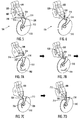
Figures 7A, 7B, 7C and 7D illustrate an example embodiment of a sequence, wherein a control component first moves from a locked state to an open state, and, finally, a lever returns to its initial position; and -
Figures 8, 9 and 10 illustrate further example embodiments enabling a lever to return to its initial position while a control component remains in a locked state. - The following embodiments are only examples. Although the specification may refer to "an" embodiment in several locations, this does not necessarily mean that each such reference is to the same embodiment(s), or that the feature only applies to a single embodiment. Single features of different embodiments may also be combined to provide other embodiments. Furthermore, words "comprising" and "including" should be understood as not limiting the described embodiments to consist of only those features that have been mentioned and such embodiments may contain also features/structures that have not been specifically mentioned.
- The Applicant has invented many improvements for the electromechanical locks, such as those disclosed in
EP applications 05112272.9 07112677.5 07112676.7 07112673.4 09180117.5 12171614.6 - Let us now turn to
Figure 1 , which illustrates an example embodiment of anelectromechanical lock 100, but with only such parts shown that are relevant to the present example embodiments. - The
electromechanical lock 100 comprises anelectronic circuit 102 configured to readdata 120 from anexternal source 110 and match thedata 120 against a predetermined criterion. In an example embodiment, besides reading, theelectronic circuit 102 may also writedata 120 to theexternal source 110. - The
electromechanical lock 100 also comprises anaccess control mechanism 104. - As shown in
Figure 1 , theelectronic circuit 102 electrically controls 122 theaccess control mechanism 104. -
Figure 2 illustrates further example embodiments of theelectromechanical lock 100. - An
electric power supply 200powers 240 both theelectronic circuit 102 and theaccess control mechanism 104. - In an example embodiment, electric energy required by the
access control mechanism 104 is generated in a self-powered fashion within theelectromechanical lock 100. - In an example embodiment, the
electric power supply 200 comprises agenerator 202. - In an example embodiment, pushing down 236 a
door handle 212 may operate 234 thegenerator 202. - In an example embodiment, pushing down 236 the
door handle 212 may also mechanically affect 242 theaccess control mechanism 104. - In an example embodiment, the
electric power supply 200 comprises abattery 204. Thebattery 204 may be a single use or rechargeable accumulator, possibly based on at least one electrochemical cell. - In an example embodiment, the
electric power supply 200 comprisesmains electricity 206, i.e., theelectromechanical lock 100 may be coupled to the general-purpose alternating-current electric power supply. - In an example embodiment, electric energy required by the
access control mechanism 104 is sporadically imported from some external source. - In an example embodiment, the
electric power supply 200 comprises asolar cell 208 that converts the energy of light directly into electricity by the photovoltaic effect. - In an example embodiment, the electric energy may be obtained from a radio frequency field utilized in radio-frequency identification (RFID) technology.
- In an example embodiment, the
external source 110 comprises aRFID tag 220 containing thedata 120. - In an example embodiment, the
external source 110 comprises NFC (Near Field Communication)technology 222 containing thedata 120, i.e., a smartphone or some other user terminal holds thedata 120. NFC is a set of standards for smartphones and similar devices to establish radio communication with each other by touching them together or bringing them into close proximity. In an example embodiment, theNFC technology 222 may be utilized to obtain 240 the electric energy for theelectronic circuit 102 and possibly also for theaccess control mechanism 104. - In an example embodiment, the
external source 110 comprises akey 224 containing thedata 120. - In an example embodiment, the
key 224 comprises theRFID tag 220 containing thedata 120. - As is shown in
Figure 2 , in an example embodiment, theelectromechanical lock 100 may be placed in alock body 210, and theaccess control mechanism 104 may control 230 alock bolt 214 moving 232 in and out of thelock body 210. -
Figures 3 and 4 show a further example embodiment of the electromechanical lock 100: theelectronic circuit 102 and theaccess control mechanism 104 may be placed inside alock cylinder 300. Thelock cylinder 300 may be placed into thelock body 210 and thelock cylinder 300 may interact 230 with thelock bolt 214. - Furthermore, the
electric power supply 200 comprises thegenerator 202 and theexternal source 110 comprises thekey 224. As thekey 224 is inserted 402 into akeyway 400 of thelock cylinder 300, thegenerator 202 is mechanically rotated 404, and, furthermore, as thekey 224 is inserted in thekeyway 400, theaccess control mechanism 104 is electronically controlled and mechanically manipulated 406. - Let us next study the
access control mechanism 104 in more detail with reference toFigures 5 and 6 . - The
access control mechanism 104 comprises acontrol component 510 movable by the electric power and including apassage 516, and alever 500 to receive mechanical power from a user. -
Figure 5 illustrates an example embodiment of thecontrol component 510 in a locked state, andFigure 6 illustrates an example embodiment of thecontrol component 510 in an open state. - In an example embodiment, the
control component 510 moves by rotating. - In an example embodiment, the
control component 510 comprises a disc. - In an example embodiment, the
control component 510 comprises a rotating disc. - In an example embodiment, the
control component 510 comprises a cut-out as thepassage 516. The cut-out may be manufactured by stamping or machining, for example. - As can be seen in
Figure 5 , thecontrol component 510 may comprise ahole 512 capable of receiving a pin (not illustrated) for attaching thecontrol component 510 to the rest of theelectromechanical lock 100. In an example embodiment, the pin may be a rotating shaft of an electric motor. Thecontrol component 510 may thus be rotated by the electric motor controlled by theelectronic circuit 102. In an example embodiment, the electric motor rotating thecontrol component 510 may also act as thegenerator 202. - The
lever 500 may also comprise anotherhole 502 capable of receiving another pin (not illustrated) for attaching thelever 500 to theelectromechanical lock 100. Thelever 500 may thus pivot 520 around the other attachment pin. - In
Figure 5 , thedata 120 does not match the predetermined criterion, whereupon thecontrol component 510 remains in the locked state such that thelever 500 advances into a contact with thecontrol component 510 outside 514 of thepassage 516 with the mechanical power. The mechanical power, received from the user thus pivots 520 thelever 500, but as thecontrol component 510 has not been rotated to the open position, atip 504 of thelever 500 cannot advance into thepassage 516, and thetip 504 of thelever 500 only meets thecontrol component 510 outside 514 of thepassage 516. - In an example embodiment illustrated in
Figure 5 , thecontrol component 510 comprises aprotruding part 518 with asloping edge 520 facing away from thepassage 516 such that as thecontrol component 510 remains in the locked state, thelever 500 advances into the contact with thesloping edge 520 of thecontrol component 510 outside 514 of thepassage 516. - In
Figure 6 , thedata 120 matches the predetermined criterion, whereupon thecontrol component 510 first moves with the electric power from a locked state to an open state, and thelever 500next advances 520 into thepassage 516 with the mechanical power. - The opening sequence is further illustrated in
Figures 7A, 7B, 7C and 7D . -
Figure 7A shows the starting position: thetip 504 of thelever 500 may not even touch the control component. As thedata 120 matches the predetermined criterion, thecontrol component 510 starts to move 700 with the electric power from a locked state to an open state. - In
Figure 7B , thelever 500next advances 520 into thepassage 516 with the mechanical power and at thesame time forces 704 thecontrol component 510 back to the locked state due toshape 702 of thepassage 516. Thetip 504 of thelever 500 may slide against areset ramp 702 formed into at least one sidewall of thepassage 516, thereby exercising pressure on thecontrol component 510 causing it to rotate in a controlled fashion back to the locked state. It is to be noted that this operation returns thecontrol component 510 back to the locked state. While the return of the otherelectromechanical lock 100 mechanics back to the locked state is not the core of the described embodiments, they will not further be described, although the return of thelever 500 to its initial position will be described. In effect, the return of theaccess control mechanism 104 will be described. - In
Figure 7C , thelever 500 has pivoted 520 to its furthermost position, and thecontrol component 510 remains in the locked state. - In
Figure 7D , as thelever 500 returns 712 to its initial position (shown inFigure 7A ), the lever 500 (or its tip 504) bypasses thecontrol component 510 remaining in the locked state. - In an example embodiment, the
control component 510 comprises a movingcontrol part 710 capable of moving 714 out of the way as thelever 500 contacts with thecontrol component 510 as thelever 500 returns 712 to its initial position and thecontrol component 510 remains in the locked state. - In an example embodiment, the
control component 510 comprises a bendingcontrol part 710 capable of bending 714 out of the way as thelever 500 contacts with thecontrol component 510 as thelever 500 returns to its initial position and thecontrol component 510 remains in the locked state. - As shown in
Figure 7C , the bendingcontrol part 710 may partly be separated byslits control component 510, whereby thebending movement 714 is enabled. - In an example embodiment illustrated in
Figure 8 , thecontrol component 510 comprises an elastic control fixing (not illustrated, but it is coupled with the hole 512) with which thecontrol component 510 is capable of moving 800 out of the way as thelever 500 contacts with thecontrol component 510 as thelever 500 returns 712 to its initial position and thecontrol component 510 remains in the locked state. The elastic control fixing may comprise an axial spring enabling an axial displacement of thecontrol component 510. - In an example embodiment illustrated in
Figure 9 , thelever 500 comprises a movinglever part 504 capable of moving out of the way as thelever 500 contacts with thecontrol component 510 as thelever 500 returns 712 to its initial position and thecontrol component 510 remains in the locked state. After thelever 500 has returned to its initial position, the movinglever part 504 moves at thedirection 900 into theposition 902. - In an example embodiment illustrated in
Figure 9 , thelever 500 comprises a spring-loaded 904part 504 both capable of retracting out of the way as thelever 500 contacts with thecontrol component 510 as thelever 500 returns to its initial position, and capable of reaching 900 out into the contact with thecontrol component 510 outside 514 of thepassage 516 as thelever 500 advances into the contact with thecontrol component 510. - In an example embodiment, the
lever 500 comprises a bending lever part (at thetip 504 of the lever, for example) capable of bending out of the way as thelever 500 contacts with thecontrol component 510 as thelever 500 returns to its initial position and thecontrol component 510 remains in the locked state. - In an example embodiment illustrated in
Figure 10 , thelever 500 comprises an elastic lever fixing (not illustrated) with which thelever 500 is capable of moving 1000 out of the way as thelever 500 contacts with thecontrol component 510 as thelever 500 returns to its initial position and thecontrol component 510 remains in the locked state. This is illustrated inFigure 10 such that thehole 512moves 1000 into theposition 1002 and thetip 504 of thelever 500 moves 1000, 712 into theposition 1004. - The invention and its embodiments are not limited to the example embodiments described above but may vary within the scope of the claims.
Claims (13)
- An electromechanical lock (100), comprising an electronic circuit (102) configured to read data (120) from an external source (110) and match the data (120) against a predetermined criterion, and an access control mechanism (104) comprising a control component (510) movable by electric power and including a passage (516), and a lever (500) to receive mechanical power from a user,
wherein, if the data (120) does not match the predetermined criterion, the control component (510) remains in the locked state such that the lever (500) advances into a contact with the control component (510) outside (514) of the passage (516) with the mechanical power, or,
provided that the data (120) matches the predetermined criterion, the control component (510) first moves with electric power from a locked state to an open state, characterized in that the lever (500) next advances (120) into the passage (516) with the mechanical power and at the same time forces (704) the control component (510) back to the locked state due to shape (702) of the passage (516), and, finally, as the lever (500) returns (712) to its initial position, the lever (500) bypasses the control component (510) remaining in the locked state. - The apparatus of claim 1, wherein the control component (510) moves by rotating.
- The apparatus of claim 1, wherein the control component (510) comprises a disc.
- The apparatus of claim 1, wherein the control component (510) comprises a rotating disc.
- The apparatus of any preceding claim, wherein the control component (510) comprises a cut-out as the passage (516).
- The apparatus of any preceding claim, wherein the control component (510) comprises a moving control part (710) capable of moving (714) out of the way as the lever (500) contacts with the control component (510) as the lever (500) returns (712) to its initial the position and the control component (510) remains in the locked state.
- The apparatus of any preceding claim, wherein the control component (510) comprises a bending control part (710) capable of bending (714) out of the way as the lever (500) contacts with the control component (510) as the lever (500) returns to its initial position and the control component (510) remains in the locked state.
- The apparatus of any preceding claim, wherein the control component (510) comprises an elastic control fixing with which the control component (510) is capable of moving (800) out of the way as the lever (500) contacts with the control component (510) as the lever (500) returns (712) to its initial position and the control component (510) remains in the locked state.
- The apparatus of any preceding claim, wherein the lever (500) comprises a moving lever part (504) capable of moving out of the way as the lever (500) contacts with the control component (510) as the lever (500) returns to its initial position and the control component (510) remains in the locked state.
- The apparatus of any preceding claim, wherein the lever (500) comprises a bending lever part capable of bending out of the way as the lever (500) contacts with the control component (510) as the lever (500) returns to its initial position and the control component (510) remains in the locked state.
- The apparatus of any preceding claim, wherein the lever (500) comprises an elastic lever fixing with which the lever (500) is capable of moving out of the way as the lever (500) contacts with the control component (510) as the lever (500) returns to its initial position and the control component (510) remains in the locked state.
- The apparatus of any preceding claim, wherein the lever (500) comprises a spring-loaded (904) part (504) both capable of retracting out of the way as the lever (500) contacts with the control component (510) as the lever (500) returns to its initial position, and capable of reaching (900) out into the contact with the control component (510) outside (514) of the passage (516) as the lever (500) advances into the contact with the control component (510).
- The apparatus of any preceding claim, wherein the control component (510) comprises a protruding part (518) with a sloping edge (520) facing away from the passage (516) such that as the control component (510) remains in the locked state, the lever (500) advances into the contact with the sloping edge (520) of the control component (510) outside (514) of the passage (516).
Priority Applications (1)
| Application Number | Priority Date | Filing Date | Title |
|---|---|---|---|
| EP13727911.3A EP2859162B1 (en) | 2012-06-12 | 2013-06-11 | Electromechanical lock |
Applications Claiming Priority (3)
| Application Number | Priority Date | Filing Date | Title |
|---|---|---|---|
| EP12171614.6A EP2674552B1 (en) | 2012-06-12 | 2012-06-12 | Electromechanical lock |
| EP13727911.3A EP2859162B1 (en) | 2012-06-12 | 2013-06-11 | Electromechanical lock |
| PCT/EP2013/061995 WO2013186198A1 (en) | 2012-06-12 | 2013-06-11 | Electromechanical lock |
Publications (2)
| Publication Number | Publication Date |
|---|---|
| EP2859162A1 EP2859162A1 (en) | 2015-04-15 |
| EP2859162B1 true EP2859162B1 (en) | 2016-07-27 |
Family
ID=48577771
Family Applications (2)
| Application Number | Title | Priority Date | Filing Date |
|---|---|---|---|
| EP12171614.6A Active EP2674552B1 (en) | 2012-06-12 | 2012-06-12 | Electromechanical lock |
| EP13727911.3A Active EP2859162B1 (en) | 2012-06-12 | 2013-06-11 | Electromechanical lock |
Family Applications Before (1)
| Application Number | Title | Priority Date | Filing Date |
|---|---|---|---|
| EP12171614.6A Active EP2674552B1 (en) | 2012-06-12 | 2012-06-12 | Electromechanical lock |
Country Status (6)
| Country | Link |
|---|---|
| US (1) | US9574376B2 (en) |
| EP (2) | EP2674552B1 (en) |
| CN (1) | CN104379857B (en) |
| CA (1) | CA2874552C (en) |
| IN (1) | IN2014KN02308A (en) |
| WO (2) | WO2013186166A1 (en) |
Families Citing this family (10)
| Publication number | Priority date | Publication date | Assignee | Title |
|---|---|---|---|---|
| ES2727676T3 (en) * | 2013-06-11 | 2019-10-17 | Iloq Oy | Electromechanical lock |
| US9704316B2 (en) | 2013-09-10 | 2017-07-11 | Gregory Paul Kirkjan | Contactless electronic access control system |
| PL3118977T3 (en) * | 2015-07-13 | 2019-12-31 | Iloq Oy | Electromechanical lock utilizing magnetic field forces |
| US11377875B2 (en) | 2016-09-19 | 2022-07-05 | Level Home, Inc. | Deadbolt position sensing |
| ES2765814T3 (en) | 2017-02-16 | 2020-06-11 | Iloq Oy | Electromechanical lock |
| PL3480395T3 (en) * | 2017-11-02 | 2020-06-15 | Iloq Oy | Electromechanical lock |
| US20230243184A1 (en) * | 2017-12-28 | 2023-08-03 | Yoho Innovative Technology Limited | Telescopic electromechanical dual-control smart lock |
| USD995266S1 (en) * | 2019-01-14 | 2023-08-15 | Iloq Oy | Key |
| USD934817S1 (en) * | 2019-02-20 | 2021-11-02 | Iloq Oy | Key |
| FR3126726B1 (en) | 2021-09-09 | 2023-07-28 | Cogelec | Method of supplying an electronic cylinder of a lock |
Family Cites Families (24)
| Publication number | Priority date | Publication date | Assignee | Title |
|---|---|---|---|---|
| US4901545A (en) * | 1987-12-28 | 1990-02-20 | Rising Star Technologies (A Partnership) | Self-contained electromechanical locking device |
| US5020891A (en) | 1988-09-14 | 1991-06-04 | Washington University | Single aperture confocal scanning biomicroscope and kit for converting single lamp biomicroscope thereto |
| DE4325753A1 (en) | 1993-07-31 | 1995-02-02 | Basf Ag | Process for the preparation of 1,4-butanediol |
| DE19539235A1 (en) * | 1994-10-25 | 1996-05-02 | Wilka Schliestechnik Gmbh | Lock cylinder with electromagnetically actuated locking pin |
| IT1297493B1 (en) * | 1997-10-03 | 1999-12-17 | Silca Spa | CYLINDER UNIT AND MECHATRONIC OPERATION KEY FOR LOCK |
| CN2337036Y (en) | 1997-11-21 | 1999-09-08 | 张碧伦 | Additional carrier for carriage for children |
| US6826935B2 (en) * | 1997-12-22 | 2004-12-07 | Security People, Inc. | Mechanical/electronic lock and key therefor |
| DE29806098U1 (en) * | 1998-04-03 | 1998-08-20 | Tst Tresor Und Schlostechnik G | Arrangement for an electronically controlled lock |
| US6442986B1 (en) * | 1998-04-07 | 2002-09-03 | Best Lock Corporation | Electronic token and lock core |
| US6615625B2 (en) * | 2000-01-25 | 2003-09-09 | Videx, Inc. | Electronic locking system |
| CN2555333Y (en) * | 2002-07-24 | 2003-06-11 | 苏州金尧彩板净化有限公司 | Key Locking device electronic interlocking mechanism |
| DE10335917A1 (en) * | 2003-08-06 | 2005-03-03 | Aug. Winkhaus Gmbh & Co. Kg | lock cylinder |
| DE602005020485D1 (en) * | 2005-12-16 | 2010-05-20 | Iloq Oy | Electromechanical lock and associated operating method |
| US7987687B2 (en) * | 2005-12-27 | 2011-08-02 | Keso Ag | Electromechanical rotary lock cylinder |
| ITMI20062007A1 (en) * | 2006-10-18 | 2008-04-19 | Iseo Serrature Spa | ELECTRONIC LOCK FOR WINDOWS |
| DK2017413T3 (en) * | 2007-07-18 | 2017-10-16 | Iloq Oy | Electromechanical lock |
| EP2017412B1 (en) * | 2007-07-18 | 2015-10-14 | iLOQ Oy | Electromechanical lock |
| ES2386819T3 (en) * | 2007-07-18 | 2012-08-31 | Iloq Oy | Electromechanical lock |
| US7530606B1 (en) | 2008-01-04 | 2009-05-12 | Richard Yang | Quick pipe connector |
| AT507583B1 (en) * | 2008-12-05 | 2010-12-15 | Evva Sicherheitstechnologie | LOCKS |
| FR2945308B1 (en) * | 2009-05-05 | 2015-04-03 | Cogelec | ELECTRONIC LOCK |
| EP2336460B1 (en) | 2009-12-21 | 2012-05-30 | iLoq Oy | Part of a modular lock cylinder |
| ES2392387T3 (en) * | 2010-01-15 | 2012-12-10 | Iloq Oy | Electromechanical lock |
| DE102010028650B4 (en) * | 2010-05-06 | 2011-11-17 | Geze Gmbh | lock |
-
2012
- 2012-06-12 EP EP12171614.6A patent/EP2674552B1/en active Active
-
2013
- 2013-06-10 CN CN201380030142.6A patent/CN104379857B/en active Active
- 2013-06-10 WO PCT/EP2013/061908 patent/WO2013186166A1/en active Application Filing
- 2013-06-10 US US14/400,246 patent/US9574376B2/en active Active
- 2013-06-11 CA CA2874552A patent/CA2874552C/en active Active
- 2013-06-11 IN IN2308KON2014 patent/IN2014KN02308A/en unknown
- 2013-06-11 EP EP13727911.3A patent/EP2859162B1/en active Active
- 2013-06-11 WO PCT/EP2013/061995 patent/WO2013186198A1/en active Application Filing
Also Published As
| Publication number | Publication date |
|---|---|
| CA2874552A1 (en) | 2013-12-19 |
| EP2859162A1 (en) | 2015-04-15 |
| US20150075235A1 (en) | 2015-03-19 |
| IN2014KN02308A (en) | 2015-05-01 |
| CN104379857B (en) | 2016-09-07 |
| EP2674552B1 (en) | 2017-01-11 |
| WO2013186166A1 (en) | 2013-12-19 |
| EP2674552A1 (en) | 2013-12-18 |
| CN104379857A (en) | 2015-02-25 |
| CA2874552C (en) | 2018-01-23 |
| US9574376B2 (en) | 2017-02-21 |
| WO2013186198A1 (en) | 2013-12-19 |
Similar Documents
| Publication | Publication Date | Title |
|---|---|---|
| EP2859162B1 (en) | Electromechanical lock | |
| US11804084B2 (en) | Contactless electronic access control system | |
| US8922333B1 (en) | Contactless electronic access control system | |
| JP6109840B2 (en) | Electromechanical lock | |
| EP3118977B1 (en) | Electromechanical lock utilizing magnetic field forces | |
| CN204966559U (en) | Mobile device and battery module thereof | |
| EP3480395B1 (en) | Electromechanical lock | |
| JP2011181303A (en) | Lid body locking structure, battery housing structure, and card type electronic device | |
| CN111786185A (en) | Adapter and rail socket | |
| EP1783694B1 (en) | Electronic lock comprising an automatic actuation system which uses a capacitive proximity sensor | |
| CN212542823U (en) | Adapter and rail socket | |
| CN219528709U (en) | Intelligent notebook and intelligent lock notebook system | |
| CN105370096A (en) | System and method for collecting states of door lock | |
| CN101751073B (en) | Mini mobile computer | |
| WO2019076367A1 (en) | Smart lock circuit and smart lock | |
| CN113216754A (en) | NFC (near field communication) commodity anti-theft system without battery | |
| CN104238655A (en) | Laptop using WIFI to achieve identification | |
| EP3070235A1 (en) | Key storing device | |
| CN104243675A (en) | Mobile phone achieving identity recognition with WIFI |
Legal Events
| Date | Code | Title | Description |
|---|---|---|---|
| PUAI | Public reference made under article 153(3) epc to a published international application that has entered the european phase |
Free format text: ORIGINAL CODE: 0009012 |
|
| 17P | Request for examination filed |
Effective date: 20141212 |
|
| AK | Designated contracting states |
Kind code of ref document: A1 Designated state(s): AL AT BE BG CH CY CZ DE DK EE ES FI FR GB GR HR HU IE IS IT LI LT LU LV MC MK MT NL NO PL PT RO RS SE SI SK SM TR |
|
| AX | Request for extension of the european patent |
Extension state: BA ME |
|
| DAX | Request for extension of the european patent (deleted) | ||
| REG | Reference to a national code |
Ref country code: DE Ref legal event code: R079 Ref document number: 602013009874 Country of ref document: DE Free format text: PREVIOUS MAIN CLASS: E05B0047060000 Ipc: E05B0015040000 |
|
| RIC1 | Information provided on ipc code assigned before grant |
Ipc: E05B 47/06 20060101ALI20151216BHEP Ipc: E05B 15/04 20060101AFI20151216BHEP Ipc: E05B 49/00 20060101ALI20151216BHEP Ipc: E05B 47/00 20060101ALI20151216BHEP |
|
| GRAP | Despatch of communication of intention to grant a patent |
Free format text: ORIGINAL CODE: EPIDOSNIGR1 |
|
| INTG | Intention to grant announced |
Effective date: 20160126 |
|
| GRAS | Grant fee paid |
Free format text: ORIGINAL CODE: EPIDOSNIGR3 |
|
| GRAA | (expected) grant |
Free format text: ORIGINAL CODE: 0009210 |
|
| AK | Designated contracting states |
Kind code of ref document: B1 Designated state(s): AL AT BE BG CH CY CZ DE DK EE ES FI FR GB GR HR HU IE IS IT LI LT LU LV MC MK MT NL NO PL PT RO RS SE SI SK SM TR |
|
| REG | Reference to a national code |
Ref country code: GB Ref legal event code: FG4D |
|
| REG | Reference to a national code |
Ref country code: CH Ref legal event code: EP |
|
| REG | Reference to a national code |
Ref country code: AT Ref legal event code: REF Ref document number: 815938 Country of ref document: AT Kind code of ref document: T Effective date: 20160815 |
|
| REG | Reference to a national code |
Ref country code: IE Ref legal event code: FG4D |
|
| REG | Reference to a national code |
Ref country code: DE Ref legal event code: R096 Ref document number: 602013009874 Country of ref document: DE |
|
| REG | Reference to a national code |
Ref country code: LT Ref legal event code: MG4D |
|
| REG | Reference to a national code |
Ref country code: NL Ref legal event code: MP Effective date: 20160727 |
|
| REG | Reference to a national code |
Ref country code: AT Ref legal event code: MK05 Ref document number: 815938 Country of ref document: AT Kind code of ref document: T Effective date: 20160727 |
|
| PG25 | Lapsed in a contracting state [announced via postgrant information from national office to epo] |
Ref country code: HR Free format text: LAPSE BECAUSE OF FAILURE TO SUBMIT A TRANSLATION OF THE DESCRIPTION OR TO PAY THE FEE WITHIN THE PRESCRIBED TIME-LIMIT Effective date: 20160727 Ref country code: FI Free format text: LAPSE BECAUSE OF FAILURE TO SUBMIT A TRANSLATION OF THE DESCRIPTION OR TO PAY THE FEE WITHIN THE PRESCRIBED TIME-LIMIT Effective date: 20160727 Ref country code: NO Free format text: LAPSE BECAUSE OF FAILURE TO SUBMIT A TRANSLATION OF THE DESCRIPTION OR TO PAY THE FEE WITHIN THE PRESCRIBED TIME-LIMIT Effective date: 20161027 Ref country code: IT Free format text: LAPSE BECAUSE OF FAILURE TO SUBMIT A TRANSLATION OF THE DESCRIPTION OR TO PAY THE FEE WITHIN THE PRESCRIBED TIME-LIMIT Effective date: 20160727 Ref country code: NL Free format text: LAPSE BECAUSE OF FAILURE TO SUBMIT A TRANSLATION OF THE DESCRIPTION OR TO PAY THE FEE WITHIN THE PRESCRIBED TIME-LIMIT Effective date: 20160727 Ref country code: LT Free format text: LAPSE BECAUSE OF FAILURE TO SUBMIT A TRANSLATION OF THE DESCRIPTION OR TO PAY THE FEE WITHIN THE PRESCRIBED TIME-LIMIT Effective date: 20160727 Ref country code: RS Free format text: LAPSE BECAUSE OF FAILURE TO SUBMIT A TRANSLATION OF THE DESCRIPTION OR TO PAY THE FEE WITHIN THE PRESCRIBED TIME-LIMIT Effective date: 20160727 Ref country code: IS Free format text: LAPSE BECAUSE OF FAILURE TO SUBMIT A TRANSLATION OF THE DESCRIPTION OR TO PAY THE FEE WITHIN THE PRESCRIBED TIME-LIMIT Effective date: 20161127 |
|
| PG25 | Lapsed in a contracting state [announced via postgrant information from national office to epo] |
Ref country code: LV Free format text: LAPSE BECAUSE OF FAILURE TO SUBMIT A TRANSLATION OF THE DESCRIPTION OR TO PAY THE FEE WITHIN THE PRESCRIBED TIME-LIMIT Effective date: 20160727 Ref country code: ES Free format text: LAPSE BECAUSE OF FAILURE TO SUBMIT A TRANSLATION OF THE DESCRIPTION OR TO PAY THE FEE WITHIN THE PRESCRIBED TIME-LIMIT Effective date: 20160727 Ref country code: AT Free format text: LAPSE BECAUSE OF FAILURE TO SUBMIT A TRANSLATION OF THE DESCRIPTION OR TO PAY THE FEE WITHIN THE PRESCRIBED TIME-LIMIT Effective date: 20160727 Ref country code: SE Free format text: LAPSE BECAUSE OF FAILURE TO SUBMIT A TRANSLATION OF THE DESCRIPTION OR TO PAY THE FEE WITHIN THE PRESCRIBED TIME-LIMIT Effective date: 20160727 Ref country code: GR Free format text: LAPSE BECAUSE OF FAILURE TO SUBMIT A TRANSLATION OF THE DESCRIPTION OR TO PAY THE FEE WITHIN THE PRESCRIBED TIME-LIMIT Effective date: 20161028 Ref country code: BE Free format text: LAPSE BECAUSE OF FAILURE TO SUBMIT A TRANSLATION OF THE DESCRIPTION OR TO PAY THE FEE WITHIN THE PRESCRIBED TIME-LIMIT Effective date: 20160727 Ref country code: PT Free format text: LAPSE BECAUSE OF FAILURE TO SUBMIT A TRANSLATION OF THE DESCRIPTION OR TO PAY THE FEE WITHIN THE PRESCRIBED TIME-LIMIT Effective date: 20161128 Ref country code: PL Free format text: LAPSE BECAUSE OF FAILURE TO SUBMIT A TRANSLATION OF THE DESCRIPTION OR TO PAY THE FEE WITHIN THE PRESCRIBED TIME-LIMIT Effective date: 20160727 |
|
| PG25 | Lapsed in a contracting state [announced via postgrant information from national office to epo] |
Ref country code: RO Free format text: LAPSE BECAUSE OF FAILURE TO SUBMIT A TRANSLATION OF THE DESCRIPTION OR TO PAY THE FEE WITHIN THE PRESCRIBED TIME-LIMIT Effective date: 20160727 Ref country code: EE Free format text: LAPSE BECAUSE OF FAILURE TO SUBMIT A TRANSLATION OF THE DESCRIPTION OR TO PAY THE FEE WITHIN THE PRESCRIBED TIME-LIMIT Effective date: 20160727 |
|
| REG | Reference to a national code |
Ref country code: DE Ref legal event code: R097 Ref document number: 602013009874 Country of ref document: DE |
|
| PG25 | Lapsed in a contracting state [announced via postgrant information from national office to epo] |
Ref country code: DK Free format text: LAPSE BECAUSE OF FAILURE TO SUBMIT A TRANSLATION OF THE DESCRIPTION OR TO PAY THE FEE WITHIN THE PRESCRIBED TIME-LIMIT Effective date: 20160727 Ref country code: SM Free format text: LAPSE BECAUSE OF FAILURE TO SUBMIT A TRANSLATION OF THE DESCRIPTION OR TO PAY THE FEE WITHIN THE PRESCRIBED TIME-LIMIT Effective date: 20160727 Ref country code: CZ Free format text: LAPSE BECAUSE OF FAILURE TO SUBMIT A TRANSLATION OF THE DESCRIPTION OR TO PAY THE FEE WITHIN THE PRESCRIBED TIME-LIMIT Effective date: 20160727 Ref country code: BG Free format text: LAPSE BECAUSE OF FAILURE TO SUBMIT A TRANSLATION OF THE DESCRIPTION OR TO PAY THE FEE WITHIN THE PRESCRIBED TIME-LIMIT Effective date: 20161027 Ref country code: SK Free format text: LAPSE BECAUSE OF FAILURE TO SUBMIT A TRANSLATION OF THE DESCRIPTION OR TO PAY THE FEE WITHIN THE PRESCRIBED TIME-LIMIT Effective date: 20160727 |
|
| PLBE | No opposition filed within time limit |
Free format text: ORIGINAL CODE: 0009261 |
|
| STAA | Information on the status of an ep patent application or granted ep patent |
Free format text: STATUS: NO OPPOSITION FILED WITHIN TIME LIMIT |
|
| 26N | No opposition filed |
Effective date: 20170502 |
|
| PG25 | Lapsed in a contracting state [announced via postgrant information from national office to epo] |
Ref country code: SI Free format text: LAPSE BECAUSE OF FAILURE TO SUBMIT A TRANSLATION OF THE DESCRIPTION OR TO PAY THE FEE WITHIN THE PRESCRIBED TIME-LIMIT Effective date: 20160727 |
|
| PG25 | Lapsed in a contracting state [announced via postgrant information from national office to epo] |
Ref country code: MC Free format text: LAPSE BECAUSE OF FAILURE TO SUBMIT A TRANSLATION OF THE DESCRIPTION OR TO PAY THE FEE WITHIN THE PRESCRIBED TIME-LIMIT Effective date: 20160727 |
|
| REG | Reference to a national code |
Ref country code: CH Ref legal event code: PL |
|
| REG | Reference to a national code |
Ref country code: IE Ref legal event code: MM4A |
|
| REG | Reference to a national code |
Ref country code: FR Ref legal event code: ST Effective date: 20180228 |
|
| PG25 | Lapsed in a contracting state [announced via postgrant information from national office to epo] |
Ref country code: CH Free format text: LAPSE BECAUSE OF NON-PAYMENT OF DUE FEES Effective date: 20170630 Ref country code: LI Free format text: LAPSE BECAUSE OF NON-PAYMENT OF DUE FEES Effective date: 20170630 Ref country code: IE Free format text: LAPSE BECAUSE OF NON-PAYMENT OF DUE FEES Effective date: 20170611 Ref country code: LU Free format text: LAPSE BECAUSE OF NON-PAYMENT OF DUE FEES Effective date: 20170611 |
|
| PG25 | Lapsed in a contracting state [announced via postgrant information from national office to epo] |
Ref country code: FR Free format text: LAPSE BECAUSE OF NON-PAYMENT OF DUE FEES Effective date: 20170630 |
|
| PG25 | Lapsed in a contracting state [announced via postgrant information from national office to epo] |
Ref country code: MT Free format text: LAPSE BECAUSE OF NON-PAYMENT OF DUE FEES Effective date: 20170611 |
|
| PG25 | Lapsed in a contracting state [announced via postgrant information from national office to epo] |
Ref country code: AL Free format text: LAPSE BECAUSE OF FAILURE TO SUBMIT A TRANSLATION OF THE DESCRIPTION OR TO PAY THE FEE WITHIN THE PRESCRIBED TIME-LIMIT Effective date: 20160727 |
|
| PG25 | Lapsed in a contracting state [announced via postgrant information from national office to epo] |
Ref country code: HU Free format text: LAPSE BECAUSE OF FAILURE TO SUBMIT A TRANSLATION OF THE DESCRIPTION OR TO PAY THE FEE WITHIN THE PRESCRIBED TIME-LIMIT; INVALID AB INITIO Effective date: 20130611 |
|
| PG25 | Lapsed in a contracting state [announced via postgrant information from national office to epo] |
Ref country code: CY Free format text: LAPSE BECAUSE OF FAILURE TO SUBMIT A TRANSLATION OF THE DESCRIPTION OR TO PAY THE FEE WITHIN THE PRESCRIBED TIME-LIMIT Effective date: 20160727 |
|
| PG25 | Lapsed in a contracting state [announced via postgrant information from national office to epo] |
Ref country code: MK Free format text: LAPSE BECAUSE OF FAILURE TO SUBMIT A TRANSLATION OF THE DESCRIPTION OR TO PAY THE FEE WITHIN THE PRESCRIBED TIME-LIMIT Effective date: 20160727 |
|
| PG25 | Lapsed in a contracting state [announced via postgrant information from national office to epo] |
Ref country code: TR Free format text: LAPSE BECAUSE OF FAILURE TO SUBMIT A TRANSLATION OF THE DESCRIPTION OR TO PAY THE FEE WITHIN THE PRESCRIBED TIME-LIMIT Effective date: 20160727 |
|
| PGFP | Annual fee paid to national office [announced via postgrant information from national office to epo] |
Ref country code: DE Payment date: 20230621 Year of fee payment: 11 |
|
| PGFP | Annual fee paid to national office [announced via postgrant information from national office to epo] |
Ref country code: GB Payment date: 20230619 Year of fee payment: 11 |