EP2858732B1 - High velocity electrostatic coalescing oil/water separator - Google Patents
High velocity electrostatic coalescing oil/water separator Download PDFInfo
- Publication number
- EP2858732B1 EP2858732B1 EP13729236.3A EP13729236A EP2858732B1 EP 2858732 B1 EP2858732 B1 EP 2858732B1 EP 13729236 A EP13729236 A EP 13729236A EP 2858732 B1 EP2858732 B1 EP 2858732B1
- Authority
- EP
- European Patent Office
- Prior art keywords
- water
- oil
- separator vessel
- vessel
- elongated separator
- Prior art date
- Legal status (The legal status is an assumption and is not a legal conclusion. Google has not performed a legal analysis and makes no representation as to the accuracy of the status listed.)
- Active
Links
- XLYOFNOQVPJJNP-UHFFFAOYSA-N water Substances O XLYOFNOQVPJJNP-UHFFFAOYSA-N 0.000 title claims description 210
- 239000000203 mixture Substances 0.000 claims description 108
- 238000000926 separation method Methods 0.000 claims description 101
- 238000000034 method Methods 0.000 claims description 51
- 230000005684 electric field Effects 0.000 claims description 22
- 239000012530 fluid Substances 0.000 claims description 22
- 239000003921 oil Substances 0.000 description 184
- 235000019198 oils Nutrition 0.000 description 164
- 230000005686 electrostatic field Effects 0.000 description 30
- 238000004581 coalescence Methods 0.000 description 20
- 230000008569 process Effects 0.000 description 17
- 239000007788 liquid Substances 0.000 description 16
- 230000009977 dual effect Effects 0.000 description 15
- 239000004020 conductor Substances 0.000 description 13
- 239000010779 crude oil Substances 0.000 description 12
- 239000012223 aqueous fraction Substances 0.000 description 9
- 230000006870 function Effects 0.000 description 9
- 239000000839 emulsion Substances 0.000 description 8
- 230000008901 benefit Effects 0.000 description 7
- 150000003839 salts Chemical class 0.000 description 6
- 238000002156 mixing Methods 0.000 description 5
- 230000007704 transition Effects 0.000 description 5
- 230000003190 augmentative effect Effects 0.000 description 4
- 238000004891 communication Methods 0.000 description 4
- 239000012212 insulator Substances 0.000 description 4
- 239000012071 phase Substances 0.000 description 4
- 238000011033 desalting Methods 0.000 description 3
- 235000019476 oil-water mixture Nutrition 0.000 description 3
- 239000004215 Carbon black (E152) Substances 0.000 description 2
- 239000000356 contaminant Substances 0.000 description 2
- 230000007423 decrease Effects 0.000 description 2
- 239000006185 dispersion Substances 0.000 description 2
- 230000000694 effects Effects 0.000 description 2
- 230000005484 gravity Effects 0.000 description 2
- 229930195733 hydrocarbon Natural products 0.000 description 2
- 150000002430 hydrocarbons Chemical class 0.000 description 2
- 239000007791 liquid phase Substances 0.000 description 2
- 230000004048 modification Effects 0.000 description 2
- 238000012986 modification Methods 0.000 description 2
- 238000012545 processing Methods 0.000 description 2
- 239000004576 sand Substances 0.000 description 2
- 238000000638 solvent extraction Methods 0.000 description 2
- 230000032258 transport Effects 0.000 description 2
- 239000007762 w/o emulsion Substances 0.000 description 2
- 230000009471 action Effects 0.000 description 1
- 230000009286 beneficial effect Effects 0.000 description 1
- 230000015572 biosynthetic process Effects 0.000 description 1
- 230000000052 comparative effect Effects 0.000 description 1
- 238000010276 construction Methods 0.000 description 1
- 230000018044 dehydration Effects 0.000 description 1
- 238000006297 dehydration reaction Methods 0.000 description 1
- 230000003292 diminished effect Effects 0.000 description 1
- 230000005611 electricity Effects 0.000 description 1
- 238000005516 engineering process Methods 0.000 description 1
- 238000002474 experimental method Methods 0.000 description 1
- 238000000605 extraction Methods 0.000 description 1
- 238000005188 flotation Methods 0.000 description 1
- 230000004907 flux Effects 0.000 description 1
- 238000005755 formation reaction Methods 0.000 description 1
- 239000000446 fuel Substances 0.000 description 1
- 239000012535 impurity Substances 0.000 description 1
- 230000006698 induction Effects 0.000 description 1
- 230000000977 initiatory effect Effects 0.000 description 1
- 238000009413 insulation Methods 0.000 description 1
- 238000000622 liquid--liquid extraction Methods 0.000 description 1
- 239000012528 membrane Substances 0.000 description 1
- 239000002184 metal Substances 0.000 description 1
- 239000003607 modifier Substances 0.000 description 1
- 230000037361 pathway Effects 0.000 description 1
- 239000003208 petroleum Substances 0.000 description 1
- 238000000746 purification Methods 0.000 description 1
- 230000004044 response Effects 0.000 description 1
- 239000000126 substance Substances 0.000 description 1
- 238000012360 testing method Methods 0.000 description 1
Images


Classifications
-
- B—PERFORMING OPERATIONS; TRANSPORTING
- B01—PHYSICAL OR CHEMICAL PROCESSES OR APPARATUS IN GENERAL
- B01D—SEPARATION
- B01D17/00—Separation of liquids, not provided for elsewhere, e.g. by thermal diffusion
- B01D17/06—Separation of liquids from each other by electricity
-
- B—PERFORMING OPERATIONS; TRANSPORTING
- B01—PHYSICAL OR CHEMICAL PROCESSES OR APPARATUS IN GENERAL
- B01D—SEPARATION
- B01D17/00—Separation of liquids, not provided for elsewhere, e.g. by thermal diffusion
- B01D17/02—Separation of non-miscible liquids
- B01D17/04—Breaking emulsions
- B01D17/045—Breaking emulsions with coalescers
-
- B—PERFORMING OPERATIONS; TRANSPORTING
- B03—SEPARATION OF SOLID MATERIALS USING LIQUIDS OR USING PNEUMATIC TABLES OR JIGS; MAGNETIC OR ELECTROSTATIC SEPARATION OF SOLID MATERIALS FROM SOLID MATERIALS OR FLUIDS; SEPARATION BY HIGH-VOLTAGE ELECTRIC FIELDS
- B03C—MAGNETIC OR ELECTROSTATIC SEPARATION OF SOLID MATERIALS FROM SOLID MATERIALS OR FLUIDS; SEPARATION BY HIGH-VOLTAGE ELECTRIC FIELDS
- B03C11/00—Separation by high-voltage electrical fields, not provided for in other groups of this subclass
-
- C—CHEMISTRY; METALLURGY
- C10—PETROLEUM, GAS OR COKE INDUSTRIES; TECHNICAL GASES CONTAINING CARBON MONOXIDE; FUELS; LUBRICANTS; PEAT
- C10G—CRACKING HYDROCARBON OILS; PRODUCTION OF LIQUID HYDROCARBON MIXTURES, e.g. BY DESTRUCTIVE HYDROGENATION, OLIGOMERISATION, POLYMERISATION; RECOVERY OF HYDROCARBON OILS FROM OIL-SHALE, OIL-SAND, OR GASES; REFINING MIXTURES MAINLY CONSISTING OF HYDROCARBONS; REFORMING OF NAPHTHA; MINERAL WAXES
- C10G33/00—Dewatering or demulsification of hydrocarbon oils
- C10G33/02—Dewatering or demulsification of hydrocarbon oils with electrical or magnetic means
-
- B—PERFORMING OPERATIONS; TRANSPORTING
- B03—SEPARATION OF SOLID MATERIALS USING LIQUIDS OR USING PNEUMATIC TABLES OR JIGS; MAGNETIC OR ELECTROSTATIC SEPARATION OF SOLID MATERIALS FROM SOLID MATERIALS OR FLUIDS; SEPARATION BY HIGH-VOLTAGE ELECTRIC FIELDS
- B03C—MAGNETIC OR ELECTROSTATIC SEPARATION OF SOLID MATERIALS FROM SOLID MATERIALS OR FLUIDS; SEPARATION BY HIGH-VOLTAGE ELECTRIC FIELDS
- B03C2201/00—Details of magnetic or electrostatic separation
- B03C2201/02—Electrostatic separation of liquids from liquids
Definitions
- This invention is in the field of electrostatic coalescence of immiscible components of a mixture, and is particularly related to the separation of water from a water-and-oil mixture.
- crude oil derived from subterranean formations.
- crude oil arrives at the earth's surface it is typically in the form of a water-and-oil mixture. That is, crude oil invariably has associated water that must be separated before the oil component can be efficiently refined into useful commercially acceptable products.
- a common technique for improving the effectiveness of oil/water separation is by use of coalescence - that is a technique of joining together smaller into larger water droplets that are more readily separated from the mixture.
- coalescence is a technique of joining together smaller into larger water droplets that are more readily separated from the mixture.
- One method of augmenting coalescence of water droplets is by subjecting the mixture to an electric field.
- Oil being a non-polar fluid, acts as a dielectric and water droplets, being polar, when subjected to an electric field are coalesced.
- Coalescence is usually practiced by establishing an electric field between electrodes and passing an oil-in-water mixture through the electric field. Since water is slightly polar, water droplets become polarized by the electric field. Polarized droplets are attracted to each other and move into and coalescence with each other. Larger droplets tend to gravitate downwardly within the mixture and the oil, having portions of the water removed therefrom, tend to gravitate upwardly within the mixture.
- Circuit for maintaining the strength of an electrostatic field generated in a fluid mixture of varying dielectric strength 4,469,582 Sublette et al. Electrically enhanced inclined plate separator 4,479,161 Henrich et al. Switching type driver circuit for fuel injector 4,581,119 Rajani et al. Apparatus for separating a dispersed liquid phase from a continuous liquid phase by electrostatic coalescence 4,581,120 Sublette Method and apparatus for separating oilfield emulsions 4,601,834 Bailes et al. Settling of liquid dispersions 4,606,801 Prestridge et al. Electrostatic mixer/separator 4,702,815 Prestridge et al.
- US 2008/0257739 describes an apparatus for separating water from a water-in-oil mixture having an elongated inlet vessel with a lower outlet end and an upper inlet end, the length thereof being a multiple of the largest vessel cross-sectional dimension.
- a separation vessel having an oil outlet and a divergent water outlet has an inlet passageway in communication with the inlet vessel lower outlet end.
- At least one electrode is positioned within the inlet vessel by which a mixture flowing therethrough is subjected to an electric field. This system will be described in more detail later with reference to Figures 1-13 .
- This invention provides a method and apparatus for separating water from a water-and-oil mixture.
- the invention is particularly useful for separating water from crude oil.
- a great deal of the energy consumed on the earth today is derived from crude oil that is found in subterranean deposits and brought to the earth's surface by wells. When the crude oil reaches the earth's surface it invariably is in the form of a water-and-oil mixture. That is, crude oil is usually found associated with water.
- one of the first requirements after the crude oil is brought to the earth's surface is to separate out and properly dispose of the water content. Methods and various systems for accomplishing this are illustrated and described herein.
- a comparative example includes an elongated inlet vessel having a lower outlet end and an upper inlet end.
- the elongated inlet vessel can typically be in the form of a pipe, the diameter of which will be determined by the quantity of crude oil to be processed. While the pipe is an example of a readily available elongated vessel, the cross-section of the elongated vessel can be square, rectangular or other shape but for all practical purposes a pipe functions completely satisfactory and is readily available and inexpensive.
- a second element making up the apparatus of this example is a separation vessel that has an upper oil outlet, a lower water outlet and an intermediate inlet passageway.
- the separation vessel can, by example, be a length of pipe having a circular cross-section and the diameter of the separation vessel can typically be the same or substantially the same as the diameter of the inlet vessel.
- the separation vessel typically is elongated with respect to the diameter and may typically be about the same in length as the inlet vessel.
- One electrode is positioned with the vessel by which a mixture flowing therethrough is subjected to an electric field.
- the electrode may be, as an example, in the form of a coil conductor that receives the voltage applied through an insulator in the wall of the inlet vessel.
- the voltage may be applied between the electrode and the inlet vessel itself when the inlet vessel is a metallic conductor.
- the electrode may be insulated or in appropriate applications may be bare, that is in electrical contact with the mixture liquid flowing through the inlet.
- the separator functions by providing short liquid flow paths. A mixture being subjected to an electric field within the vessel is immediately passed to the separation vessel where passageways are provided for downward flow of separated water and upward flow of oil having a substantial portion of the water extracted therefrom.
- the apparatus for separating water from a water-and-oil mixture is arranged in a parallel relationship to adjust for varying quantities of crude oil being treated.
- the apparatus includes a first and a second elongated separator vessel both oriented on an incline and connected to one another so that the oil predominant flow exiting the outlet of the first vessel enters the inlet of the second vessel, where it is once again exposed to an electric field. Substantially dry oil then exits the second vessel.
- the water-and-oil mixture enters the first vessel below the electrode but above the water level control in the lower end or water collection portion of the vessel.
- At least one of the separator vessels may include a plurality of baffles arranged parallel one another in the water collection portion of the vessel. The baffles may be horizontal, vertical, or, preferably, angled.
- the first vessel may be arranged so that it is at the same elevation as that of the second vessel or at a different elevation.
- the inlet of the first or second vessel is located below the electrode and above the water level control.
- a pretreatment or degasser unit may be connected to the inlet of the first elongated separator vessel.
- the first vessel can run a bare electrode in circuit relationship to an AC voltage source at a lower potential.
- the ability to use a bare electrode is one advantage of the first vessel being an upflow vessel, the flow being pre-treated in the AC field.
- the moderate water fraction of the mixture exiting the first vessel and entering the second vessel, which can be an upflow or downflow vessel, allows for the use of an insulated electrode which may be in circuit relationship to a DC voltage source at a higher potential.
- the voltage source may include reactance.
- the second vessel could also use a bare electrode when configured as an upflow vessel
- a method of separating water from the water-and-oil mixture includes the steps of:
- each separator vessel is arranged below the electrode of the vessel to provide for a desired direction of flow.
- a portion of the first oil predominant fluid flowing out of the outlet of the first elongated separator vessel and into the inlet of a second or third elongated separator vessel may be a wet oil or a medium-wet oil portion.
- a second portion of the first oil predominant fluid may also be passed through an outlet and along a path which bypasses the second (or other subsequent) elongated separator vessels.
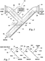
- FIG. 1 The basic prior art concept is illustrated in its simplest example in Figure 1 .
- Basically it includes an elongated inlet vessel 10 having a lower outlet end 12 and an upper inlet end 14.
- an electrode 16 Positioned within inlet vessel 10 is an electrode 16 that provides an electrostatic field through which inlet liquid, identified in Figure 1 as "feed”, flows.
- electrode 16 shown in dotted outline, is positioned within vessel 10 in which the vessel 10 is of conductive material, that is metal, so that the electrostatic field is established between electrode 16 and the wall of vessel 10.
- Inlet vessel 10 is elongated, that is, it has a length measured from the upper inlet end 14 to the lower outlet end 12 that is a multiple of the largest vessel cross-sectional dimension.
- the inlet vessel 10 is in the form of a pipe, that is, a vessel that, in cross-section, is round.
- the length of vessel 10 should preferably be about twice the vessel diameter, however the precise length is not a critical aspect except that it is important that the vessel 10 be elongated so that fluid flowing therethrough is exposed for a minimum length of time to the electrostatic field established by electrode 16.
- a second basic element of the apparatus of Figure 1 is a separation vessel 18.
- Vessel 18 has an upper oil outlet end 20 and a lower water outlet end 22. Further, separation vessel 18 has an intermediate inlet passageway 24 that communicates with the inlet vessel lower outlet end 12.
- an inlet flange fitting 26 is secured to the upper inlet end of inlet vessel 10 and a similar outlet flange fitting 28 is secured to the upper oil outlet end 20 of separation vessel 18.
- Flange fittings 26 and 28 provide convenient devices for connecting the system of Figure 1 to piping but are not otherwise involved in the performance of the system.
- the lower water outlet end 22 of separation vessel 18 is provided with a pipe fitting 30 by which water separated by the system may be carried away for disposal or further treatment.
- a mixture of oil and water enters the system by way of inlet flange fitting 26 where it passes into inlet vessel 10.
- the mixture flows through the elongated inlet vessel that is preferably downwardly sloped as indicated. Sloping the inlet vessel helps allow a high liquid flux past the electrodes.
- Within the inlet vessel the mixture is exposed to an electrostatic field. If electrode 16 within the inlet vessel is covered with insulation then electricity is not directly conducted from the electrode 16 to the mixture but instead only an electrostatic field is maintained within vessel 10 to which the mixture is exposed.
- an insulated electrode 16 the voltage between the electrode and the wall of vessel 10 can be significant so that an electrostatic field is applied to the inlet mixture.
- the electrostatic field causes water droplets within the mixture to rapidly coalesce.
- the mixture with a significant portion of the water therein coalesced into large droplets immediately passes directly into separator vessel 18 that preferably is at an angle perpendicular to the longitudinal axis of inlet vessel 10.
- separator vessel 18 that preferably is at an angle perpendicular to the longitudinal axis of inlet vessel 10.
- Figure 1 the longitudinal axis of inlet vessel 10 is indicated by the numeral 32 while the longitudinal axis of separation vessel 18 is indicated by the numeral 34.
- separation vessel 18 the inwardly flowing mixture is offered an immediate opportunity to separate into heavier and lighter components.
- the heavier component separates from the mixture and flows downwardly within the sloped separation vessel 18 into a water collection portion 36 which is the portion of vessel 18 below inlet passageway 24.
- Water within water collection portion 36 is maintained at a selected level 38 by means of a water level control 40.
- the water level control 40 is illustrated diagrammatically since such devices are frequently and customarily used in oil/water separation and are well known to any practitioner in the art.
- a typical water level control system is illustrated in and will subsequently be described with reference to Figure 8 .
- the water level control 40 operates a valve (not seen) connected to the pipe fitting 30 to drain water as it accumulates within the vessel lower portion 36 so that the level 38 stays at a pre-selected height within water collection portion 36.
- the mixture flowing out of inlet vessel 10 through lower outlet end 12 separates and the lighter component is carried upwardly into an oil collection portion 42 of separation vessel 18.
- the oil component of the feed mixture having at least a substantial portion of the water extracted therefrom flows through upper oil outlet end 20 of inlet vessel 10 and through outlet flange fitting 28 for transportation to a pipeline where it may be moved to a refinery, or is conveyed to a facility for storage or further processing.
- the system for separating water from a water-in-oil mixture of Figure 1 is of ultimate simplicity compared to most oil/water separation equipment in use today and yet is arranged to provide improved performance.
- a unique aspect of the separation system of Figure 1 is that an oil/water mixture is subjected to an electrostatic field and immediately thereafter passes for separation with the water component flowing in one direction and the oil component flowing in an opposite direction.
- the sloped arrangements of inlet vessel 10 and separation vessel 18 provide immediate gravity-assisted separation of a water-in-oil mixture after exposure to an electrostatic field.
- the apparatus of Figure 1 provides the most immediate and effective separation of oil and water in the simplest possible flow arrangement as compared with other known systems.
- FIG. 1 the rudiments of the method of applying an electrostatic field to the mixture within inlet vessel 10 is illustrated.
- a voltage source 44 provides a voltage output between conductors 46 and 48.
- Conductor 48 is secured to the sidewall of inlet vessel 10 while conductor 46 is fed through an insulator 50 that extends through the sidewall of vessel 10 to electrode 16.
- Voltage across conductors 46 and 48 may be an AC voltage, a DC voltage, a pulsing DC voltage or a dual frequency voltage.
- the particular voltage applied to create an electrostatic field within the inlet vessel is not a critical element since much work has been done to define the advantages and disadvantages of various voltage systems used to augment coalescence of water in a water-in-oil mixture.
- United States Patent No. 6,860,979 teaches a dual frequency electrostatic coalescence system that may be applied to the apparatus of Figure 1 . Such a dual frequency system is better illustrated and will be discussed with reference to Figure 6 .
- Figure 1 The basic system illustrated in Figure 1 is susceptible of a variety of modifications.
- Figure 2 shows one example of a modification of Figure 1 in which the inlet vessel 10, lower outlet 12, upper inlet 14, and electrode 16 all have the same element number and same purpose as described with reference to Figure 1 .
- Inlet vessel lower end 12 is connected in a straight line with a water collection portion 36A that has a water level control 40 to maintain a water level 38 as described with reference to Figure 1 .
- the lower water outlet end 22 of the water collection portion in Figure 2 connects to the inlet 52 of a water treatment process vessel 54 that is illustrative of any system that provides for treating and/or disposing of water extracted from the inlet mixture.
- the water treatment process 54 may include simply a disposal of the water extracted from the inlet water/oil mixture or it may represent further treatment to remove any residuary oil carried over from the inlet mixture, such as a hydrocyclone, a centrifugal force separator, a gravity separator, a corrugated plate separator, a flotation cell or a filter.
- Oil treatment process vessel 58 is emblematic of any system for further handling, transports, treatment or storage of oil separated by the system of Figure 2 .
- the oil treatment process 58 can be a storage facility where crude oil having a substantial portion of the water extracted therefrom is stored prior to being transported for further use, such as to a refinery for processing.
- Figure 2 illustrates water treatment process vessel 54 and oil treatment vessel 58 as emblematic of further treatment of separated oil and water exiting from the systems.
- Figure 2 compared to Figure 1 shows a different geometrical arrangement of the flow paths of oil and water that have been separated from an inlet oil-in-water mixture.
- separated oil changes directions and moves upwardly at an angle relative to the flow path of the inlet mixture.
- Figure 2 compared to Figure 1 , separated water continues in the same flow path of the inlet vessel. Irrespective of these differences the basic function of the systems of Figures 1 and 2 is the same.
- FIG. 1 shows an arrangement wherein an inlet mixture of oil-in-water is subject to an electrostatic field and immediately thereafter separate passageways are provided by which the separated water and oil flows in different directions.
- Figure 3 shows another alternate system.
- inlet vessel 10 is elongated and downwardly sloped, the same as shown in Figures 1 and 2 .
- the oil collection portion 42B is vertically upward.
- the longitudinal axis 32 intersects the separation vessel longitudinal axis 34 at an angle of about 45°.
- the mixture after having passed through the electrostatic field established by electrode 16 within inlet vessel 10 turns and enters horizontally into oil collection portion 42B that is in vertical alignment with water collection portion 36B. Separated water from the mixture coalesced by action of the electrode 16 immediately turns downwardly into the water collection portion 36B and the separated lighter oil component immediately turns upwardly into oil collection portion 42B and flows out upper oil outlet 20.
- the inlet mixture is subjected to an electrostatic field and immediately thereafter the flow from the inlet mixture enters a divergent path in which separated water can flow in a direction divergent from the separated oil.
- the separated water component immediately diverges into a downward path into water collection portion 36B while the separated oil component flows in the opposite direction, that is, upwardly into oil collection portion 42.
- Figure 3 provides the same unique concept as Figures 1 and 2 , that is, a mixture inlet through an elongated vessel in which the mixture is subject to an electrostatic field followed immediately by divergent flow pathways for the separated water and oil components.
- FIG 9 shows another alternate system.
- the inlet vessel 10, lower outlet 12, upper inlet 14, and electrode 16 all have the same element number and same purpose as described with reference to Figures 1 , 2 and 3 .
- Inlet vessel 10 is elongated and downwardly sloped but with flange fitting 26 oriented to receive a vertical feed.
- Both the water collection portion 36C and the oil collection portion 42C of the separator vessel 18 are aligned along the separation vessel longitudinal axis 34 and oriented at an angle of about 22.5° relative to the horizontal.
- the inlet vessel longitudinal axis 32 is perpendicular to the separation vessel longitudinal axis 34.
- the mixture separates, after having passed through the electrostatic field established by electrode 16 within inlet vessel 10, and the separated water turns angularly downward into the water collection portion 36C and the separated lighter oil component turns angularly upward into the oil collection portion 42C and flows out upper oil outlet 20.
- the outlet flange fitting 28 is oriented such that it can connect to a vertically oriented oil treatment process area.
- the inlet mixture is subjected to an electrostatic field and immediately thereafter the flow from the inlet mixture enters a divergent path in which separated water can flow in a direction divergent from the separated oil.
- the angle of inlet vessel 10 can range from 0° to 45° relative to vertical and the angle of the separation vessel 18 can range from 0° to 45° relative to horizontal.
- Figures 1 , 2 , 3 and 9 each make use of plural electrostatic fields.
- a second electrode 60 is positioned within the oil collection portion 42, that is, there is a second electrode 60 within oil collection portion 42 of Figure 1 , within oil collection 42A of Figure 2 , within oil collection 42B of Figure 3 , and within oil collection 42C of Figure 9 .
- Each of the second electrodes provide electrostatic fields in the same way as the primary electrode 16 in each embodiment and serves to further aid in the coalescence of any water remaining in the separated oil after first separation has taken place.
- the secondary electrodes 60 may be insulated or if the percentage of water remaining in the mixture within the oil collection portion of the apparatus has diminished sufficiently then the secondary electrodes 60 may be bare electrodes operating at lower voltages.
- Figure 4 shows how the basic separation system may be used in series to more completely separate water from a water-in-oil mixture.
- Figure 4 shows an inlet manifold 62 by which a water-in-oil mixture is fed into a first separation system generally indicated by the numeral 64 that has the components with the same numerical identification as Figure 1 .
- Outlet flange 28 of first separation system 64 connects to an inlet flange 26A of a second separation system 66.
- the outlet flange 28A of separation system 66 communicates with an outlet manifold 68 whereby the oil component of the mixture that flows in inlet manifold 62 is collected.
- first separation system 64 and second separation system 66 each function identically as has been described with reference to Figure 1 in that each has an inlet vessel 10, a water collection portion 36 and an oil collection portion 42.
- Each inlet vessel has an electrode 16 and each water collection portion 36 has a pipe fitting by which water separated from the feed mixture is conveyed away from the separation system.
- FIG. 4 One difference in Figure 4 compared to Figure 1 is that a gas outlet is illustrated in communication with each of the inlet vessels 10 and 10A.
- Each gas outlet 70 and 70A is connected by piping 72 by which gas separated from the system can be carried away, such as to a gas collection facility, a flare or so forth.
- Figure 7 is a diagrammatic illustration of how the separation system of Figure 2 can be connected in series.
- Figure 7 diagrammatically shows a separation system 74 that functions as illustrated and described with reference to Figure 2 and identical separation systems 76 and 78 connected in series. This is illustrative of the fact that separation systems as described herein may be connected in series with as many as necessary substantially identical separation systems connected in series to achieve the level of separation required.
- Figure 4 shows two separation systems 64 and 66 extending in series from an inlet manifold 62 to an outlet manifold 68. It is easy to see that any number of the systems illustrated in Figure 4 can be placed side-by-side, in parallel, each extending from inlet manifold 62 to outlet manifold 68. In like manner the system of Figure 7 could easily be placed in parallel with as many separation systems as required according to the volume of a water-in-oil mixture to be treated.
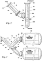
- FIG. 5 illustrates how a separation system may be employed in a desalter system.
- a first separation system 64 as is described with reference to Figure 1 functions to provide separated oil at outlet flange fitting 28 that is connected to a T-fitting 80 having a wash water inlet 82.
- the separated oil flowing from outlet flange 28 mixes with wash water in T-fitting 80, and the mixture passes out of the T-fitting through outlet 84, through a mixing valve 86 and through an inlet 88 pipe to a desalter vessel 90.
- a quiet zone is provided allowing the oil and water to separate.
- the water introduced through wash water inlet 82 absorbs salt content in the oil discharged from first separator system 64. From desalter vessel 90 water passes out through outlet 92 and oil having substantially all the water and substantially all the salt removed therefrom flows out through oil outlet 94.
- FIG. 6 shows a further illustration of how the separation systems may be used in a desalting arrangement.
- a first separation system 64 as illustrated and described with reference to Figure 1 , provides separated oil through outlet flange 24 into a T-fitting 80 having a water inlet 82 as described in Figure 5 .
- the mixture passes through mixing valve 86 as described and into another inlet flange fitting 26 of a second separation system 66 that again is the same as the basic separation system of Figure 1 .
- the separated oil flowing through outlet fitting 28A enters a desalter vessel 90 where the water and oil components of the mixture separate by gravitation with the water having dissolved salt therein and relatively salt-free oil passing upwardly and out of the desalter through oil outlet 94.
- Figure 6 shows more details of circuitry by which a voltage may be applied to an electrode within a separation system to which reference will be made subsequently.
- Figure 8 shows one way in which separation systems can be added in series.
- an oil/water mixture enters through an inlet 96 into a preliminary separator 98 that is in the form of a vertical vessel having a gas outlet 100 at the top.
- Liquid passes downwardly in preliminary separator 98 with easily separated water component settling to the bottom into a water level 38 maintained by a water level control 40.
- the control 40 operates a water discharge valve 102 so that the level 38 is maintained within vessel 98.
- a pipe outlet fitting 30 provides for conveying water away from preliminary separator 98.
- the mixture having gas and easily separated water removed therefrom flows into a first separator system 74 like that described in Figure 2 .
- separation system 74 As water is separated from the oil content of the mixture within separation system 74 it flows downwardly into water collection portion 36A and ultimately is drained out pipe outlet fitting 30. Oil from the mixture moves upwardly through oil collection portion 42 where it is again exposed to an electrostatic field by second electrode 60. The separated oil moves through oil outlet 56 and into a second separation system 64 and through downwardly inclined inlet vessel 10 having an electrode 16 therein. In the separation system 64 the mixture is treated as has been described with reference to Figure 1 , that is, in a basic separation system.
- inlet vessel 10 From inlet vessel 10, the mixture, after being subjected to the electrostatic field provided by electrode 16, flows into separation vessel 18, the water being channeled downwardly into the water collection portion 36 where it mixes with water draining out of water collection portions 36A of separation system 74 and passes out of the system through a pipe outlet 30.
- the oil passing out of inlet vessel 10 is channeled upwardly through oil collection portion 42 and out through outlet flange fitting 28, all in the manner as described with reference to Figure 1 .
- Figure 8 is an illustration of how the separation system lends itself to a variety of combinations, all achieved with the basic concepts as revealed in Figure 1 .
- the mixture is subjected to electrostatic field provided by four (4) electrodes.
- the strength of the electrostatic field of successive electrodes can be increased since each is in a portion of the system wherein the water content of the mixture has been reduced.
- electrodes 16 and 60 of separation system 74 may be insulated, electrodes 16 and 60 of separation system 64 may be uninsulated, that is bare.
- different electrode configurations may be used for electrodes 16 and 60 in order to achieve the desired electrostatic field.
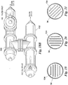
- electrodes 16A are in the form of parallel plates.
- the electrodes 16B are in the form of concentric cylindrical members 16B, while in Figure 12 a coaxial electrode 16C is in the shape of a rod surrounded by a concentric cylindrical member 16D.
- Second electrode 60 may have any of the cross-sectional arrangements shown in Figures 10, 11 and 12 .
- each of the electrodes employed in the separation systems described herein is supplied by a voltage potential which may be an AC voltage, a DC voltage, a rectified AC voltage or an AC voltage having selected frequencies and wave forms.
- An effective voltage format for use with the electrostatic separator systems is a dual frequency voltage as described in detail in United States Patent No. 6,860,979 entitled “Dual Frequency Electrostatic Coalescence.”
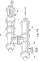
- Figure 6 shows a basic circuit revealed in this patent by which a dual frequency voltage is applied to electrode 16 of separation system 64. In this dual frequency circuit a three-phase voltage source 104 is applied to a rectifier 106 to produce a voltage on a DC bus 108.
- Voltage from DC bus 108 supplies a modulator 110 that, by signals fed on conductors 112, controls a chopper 114 that provides an AC voltage of selectable frequency to the primary 116 of a transformer 118.
- the secondary 120 of transformer 118 applies voltage between ground 122 and a conductor 124 that supply voltage passing through insulator 50 to electrode 16.
- the circuit of Figure 6 provides a method of augmenting the separation of the oil and water components of a mixture flowing through inlet vessel 10 by providing an AC voltage source of a readily selectable frequency F1 that is modulated in intensity at a selected frequency F2.
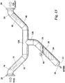
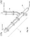
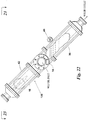
- Figure 13 illustrates an alternate as compared to the basic prior art example of Figure 1 .
- a horizontal transition vessel 126 typically in the form, as illustrated, of a length of pipe, interconnects oil collection vessel 42 with inlet vessel 10.
- a tee fitting 128, extends from the bottom of horizontal transition vessel 126 and connects to the inlet of water collection vessel 36.
- water separating in inlet vessel 10 and oil collection vessel 42 settles to the bottom of horizontal transition vessel 126 and drains out through tee fitting 128 into water collection vessel 36 while encountering reduced turbulence.
- FIG. 1 the basic configurations of the separator are illustrated in Figures 1 , 2 , 3 , 9 and 13 .
- Different systems by which this separator system can be applied are illustrated in Figures 4 , 5 , 6 , 7 and 8 .
- Figures 5 and 6 illustrate specifically how the separator system herein can be employed in a desalting system in which wash water is utilized. It is important to emphasize that the illustrations of how the separator system can be modified into various configurations, as exemplified in Figures 4 through 8 , are examples only and by no means are illustrated as the only arrangements by which the separator system can be employed.
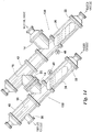
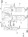
- a first separation vessel 130 and a second separation vessel 132 are arranged one above the other, each vessel 130 being an upflow leg or stage that has the wet oil inlet 14 located below the electrode 16 but above the water level control 40 (and therefore above the water level 38).
- the orientation of the vessels 130, 132 may vary from vertical to horizontal (see Figures 15 to 15B ) relative to one another.
- a vertical orientation has logistical advantages and a horizontal orientation has fluid flow advantages. Varying between the two orientations blends the advantages of both orientations.
- the wet oil As the wet oil enters through inlet 14 of the first vessel 130 below the electrode 16, the wet oil is substantially immediately affected by the electric field. The largest water droplets coalesce and flow downward into the water collection portion 26 before the wet oil encounters the electrode 16.
- the angle of the vessel 130 relative to horizontal (see e.g., Figure 15 ) allows the expedited countercurrent removal of the coalesced water to the water collection portion 26.
- the drier oil passes from the outlet 20 of the first vessel 130 and enters the inlet 14 of second vessel 132 below the electrode 16, where the above separation process is repeated.
- Each vessel 130, 132 is equipped with a gas outlet 70 by which gas separated from the system can be carried away, such as to a gas collection facility, a flare or so forth.
- a plurality of baffles 134 that are arranged parallel to one another may be provided in the water collection portion 26 of each vessel 130, 132.
- the baffles 134 which are preferably oriented parallel to the axis of the vessel 130, 132 may be vertical, horizontal, or angled baffles (see Figures 19 to 21 ).
- a vertical baffle decreases the Reynolds Number and, therefore, system turbulence.
- a horizontal baffle decreases the Reynolds Number and settling distance.
- a horizontal configuration increases the number of surfaces on which sand may accumulate. Additionally, the separated oil droplets must cross the water flow in order to travel upward and recombine with the continuous oil phase.
- the separated oil droplets cross the water flow at the wall where flow velocity is a minimum.
- a degasser or pretreatment unit 136 may be connected to the inlet 14 of the first separator vessel 130. Pretreatment prevents excessive gas from entering into vessel 130 (and 132) and reduces the inlet water volume by initiating water removal.
- the pretreatment unit 136 is a PORTA-TEST WHIRLYSCRUB® VTM vertical centrifugal separator (Cameron Corp. Process Systems, formerly National Tank Company Corp., Houston, Texas) or CONSEPT ICDTM centrifugal separator (also Cameron Corp. Process Systems, formerly National Tank Company Corp., Houston, Texas).
- pretreatment unit 136 may include a water collection portion 138.
- the up flow configuration has a limit on the amount of water that can be removed.
- the drag of the upward flowing oil prevents small amounts of water from falling into the water collection portion 36 of the vessel 130, 132, and this configuration can dry oil only to moderate fractions.
- a down flow configuration can yield oil with a low ( ⁇ 1%) water fraction.
- an effective voltage format for use with the electrostatic separator systems of this invention is a dual frequency voltage as described in detail in United States Patent No. 6,860,979 entitled “Dual Frequency Electrostatic Coalescence” and incorporated herein by reference.
- the moderately wet inflow also provides an opportunity to use an insulated electrode 16.
- first stage electrode 16 is a bare electrode used in combination with AC technology. Electrode 16 causes water droplets to coalesce and fall out of the oil-water mixture into the water collection portion 36. Because of the high density of the water relative to the oil and its low viscosity, most of the water can fall out of the mixture into the water collection portion 36.
- the moderately dry oil enters the second vessel 132 about even with the electrode 60.
- Second stage electrode 60 performs the same function as that of the first stage electrode 16.
- Electrode 60 may be an insulated electrode and used in combination with AC or with dual polarity and dual frequency techniques. With the momentum of the water and the mixture being in the same direction, the drag on the oil-water mixture is reduced and much more of the remaining water can fall out into the water collection portion 36 of the second vessel 132. This water exits at the lower water outlet end 22 and nearly dry oil exits from the upper oil outlet end 20. Note that because upper oil outlet end 20 of the first vessel 130 and the inlet 14 of the second vessel 132 are both at the upper ends of the vessels 130, 132, this configuration occupies less space than the systems illustrated, for example, in Figures 14 and 15 .
- an additional oil outlet 20a is provided that routes oil dry enough to meet a user's requirements on a dry oil path 142 that bypasses the second separator vessel 132.
- wet oil about 30-70% H 2 O
- dry oil about ⁇ 1% H 2 O
- the balance of the medium-wet or moderately dry oil about 5-10% H 2 O
- Dry oil then exits the second vessel 132 through outlet 20 D and along dry oil path 142.
- the flow through outlet 20 A is controlled to ensure that any oil that exceeds the user's requirements is not routed through the outlet 20 A (thereby bypassing the second vessel 132). The same holds true for outlet 20 D .
- the first separator vessel 130 which is an up flow vessel, includes two additional outlets 20 A and 20 B .
- outlet 20 B is located in close proximity to the wet oil inlet 14.
- a portion of the wet oil is diverted to outlet 20 B and into inlet 14 (2) of the second separator vessel 132, which is also an up flow vessel.
- Dry oil that meets the user's requirements exits through additional outlet 20 A located at the top end of vessel 130 and travels along path 142.
- the second separator vessel 132 converts the wet oil from the first vessel 130 to a medium-wet oil, which exits the second vessel 132 through outlet 20 D and travels along medium-wet oil path 144 to the inlet 14 (3B) of an additional or third separator vessel 140.
- Vessel 240 is a down flow vessel substantially similar in structure to that of vessels 130, 132 as illustrated in, for example, Figures 24A & B .
- Medium- or moderately wet oil which passes through outlet 20 C of the first vessel 130 also travels along medium-wet oil path 144 to the inlet 14 (3A) of a third vessel 140. Dry oil then exits through outlet 20 E of the third vessel 140 and travels along dry oil path 142.
Landscapes
- Chemical & Material Sciences (AREA)
- Chemical Kinetics & Catalysis (AREA)
- Oil, Petroleum & Natural Gas (AREA)
- Physics & Mathematics (AREA)
- Thermal Sciences (AREA)
- Engineering & Computer Science (AREA)
- General Chemical & Material Sciences (AREA)
- Organic Chemistry (AREA)
- Production Of Liquid Hydrocarbon Mixture For Refining Petroleum (AREA)
- Electrostatic Separation (AREA)
Description
- This invention is in the field of electrostatic coalescence of immiscible components of a mixture, and is particularly related to the separation of water from a water-and-oil mixture.
- One of the world's most useful sources of energy is crude oil, derived from subterranean formations. When crude oil arrives at the earth's surface it is typically in the form of a water-and-oil mixture. That is, crude oil invariably has associated water that must be separated before the oil component can be efficiently refined into useful commercially acceptable products.
- A common technique for improving the effectiveness of oil/water separation is by use of coalescence - that is a technique of joining together smaller into larger water droplets that are more readily separated from the mixture. As water droplet size increases, the dynamics of gravitational separation improve. One method of augmenting coalescence of water droplets is by subjecting the mixture to an electric field. Oil, being a non-polar fluid, acts as a dielectric and water droplets, being polar, when subjected to an electric field are coalesced. Coalescence is usually practiced by establishing an electric field between electrodes and passing an oil-in-water mixture through the electric field. Since water is slightly polar, water droplets become polarized by the electric field. Polarized droplets are attracted to each other and move into and coalescence with each other. Larger droplets tend to gravitate downwardly within the mixture and the oil, having portions of the water removed therefrom, tend to gravitate upwardly within the mixture.
- Much work has been done in the area of electrostatic coalescence of a mixture to augment separation of oil and water components. Background information relating to the inventive subject matter contained herein can be obtained from the following United States patents:
Patent Number Inventor Title 1,116,299 Laird et al. Process of treating petroleum emulsions 1,276,387 McKibben Method of separating associated liquids 1,838,931 Fisher Apparatus for converting commercial frequency circuits into high frequency circuits 2,120,932 Dillon High frequency induction dehydrator 2,849,395 Wintermute Method and apparatus for electrical separation of emulsions 3,772,180 Prestridge Electric treater 3,839,176 McCoy Method and apparatus for removing contaminants from liquids 3,847,775 Prestridge Process for electrical coalescing of water 4,126,537 Prestridge Method and apparatus for separation of fluids with an electric field 4,161,439 Warren et al. Apparatus for application of electrostatic fields to mixing and separating fluids 4,200,516 Pope Electrostatic coalescing system 4,204,934 Warren et al. Process for application of electrostatic fields to mixing and separating fluids 4,224,124 Pope Electrostatic coalescing system 4,283,290 Davies Purification utilizing liquid membrane with electrostatic coalescence 4,290,882 Dempsey Electrostatic separation of impurities phase from liquid-liquid extraction 4,308,127 Prestridge Separation of emulsions with electric field 4,400,253 Prestridge Voltage control system for electrostatic oil treater 4,415,426 Hsu et al. Electrodes for electrical coalescence of liquid emulsions 4,417,971 Ferrin et al. Circuit for maintaining the strength of an electrostatic field generated in a fluid mixture of varying dielectric strength 4,469,582 Sublette et al. Electrically enhanced inclined plate separator 4,479,161 Henrich et al. Switching type driver circuit for fuel injector 4,581,119 Rajani et al. Apparatus for separating a dispersed liquid phase from a continuous liquid phase by electrostatic coalescence 4,581,120 Sublette Method and apparatus for separating oilfield emulsions 4,601,834 Bailes et al. Settling of liquid dispersions 4,606,801 Prestridge et al. Electrostatic mixer/separator 4,702,815 Prestridge et al. Distributed charge composition electrodes and desalting system 4,747,921 Bailes Liquid-liquid contacting 4,767,515 Scott et al. Surface area generation and droplet size control in solvent extraction systems utilizing high intensity electric fields 4,804,453 Sublette et al. Resolution of emulsions with multiple electric fields 5,147,045 Chi et al. Particulate separations by electrostatic coalescence 5,411,651 Yamaguchi et al. Method for electrostatic liquid/liquid contactor 5,421,972 Hickey et al. Process and apparatus for removing soluble contaminants from hydrocarbon streams 5,464,522 MacEdmondson Electrostatic oil emulsion treating method and apparatus 5,543,027 Yamaguchi et al. Apparatus for electrostatic liquid/liquid contactor 5,565,078 Sams et al. Apparatus for augmenting the coalescence of water in a water-in-oil emulsion 5,575,896 Sams et al. Method and apparatus for oil/water separation using a dual electrode centrifugal coalescer 5,643,431 Sams et al. Method for augmenting the coalescence of water in a water-in-oil emulsion 5,824,203 Remo Method and means for changing characteristics of substances 6,010,634 Sams et al. System and method for separating mingled heavier and lighter components of a liquid stream 6,113,765 Wagner et al. Methods for enhanced resolution of hydrocarbon continuous emulsions or dispersions with conductivity modifiers 6,860,979 Sams Dual Frequency Electrostatic Coalescence - Additionally,
US 2008/0257739 describes an apparatus for separating water from a water-in-oil mixture having an elongated inlet vessel with a lower outlet end and an upper inlet end, the length thereof being a multiple of the largest vessel cross-sectional dimension. A separation vessel having an oil outlet and a divergent water outlet has an inlet passageway in communication with the inlet vessel lower outlet end. At least one electrode is positioned within the inlet vessel by which a mixture flowing therethrough is subjected to an electric field. This system will be described in more detail later with reference toFigures 1-13 . - Various aspects of the invention are set out in the appended claims.
- This invention provides a method and apparatus for separating water from a water-and-oil mixture. The invention is particularly useful for separating water from crude oil. A great deal of the energy consumed on the earth today is derived from crude oil that is found in subterranean deposits and brought to the earth's surface by wells. When the crude oil reaches the earth's surface it invariably is in the form of a water-and-oil mixture. That is, crude oil is usually found associated with water. In order to successfully and economically transport, refine and make use of crude oil, one of the first requirements after the crude oil is brought to the earth's surface is to separate out and properly dispose of the water content. Methods and various systems for accomplishing this are illustrated and described herein.
- A comparative example includes an elongated inlet vessel having a lower outlet end and an upper inlet end. The elongated inlet vessel can typically be in the form of a pipe, the diameter of which will be determined by the quantity of crude oil to be processed. While the pipe is an example of a readily available elongated vessel, the cross-section of the elongated vessel can be square, rectangular or other shape but for all practical purposes a pipe functions completely satisfactory and is readily available and inexpensive.
- A second element making up the apparatus of this example is a separation vessel that has an upper oil outlet, a lower water outlet and an intermediate inlet passageway. As with the inlet vessel, the separation vessel can, by example, be a length of pipe having a circular cross-section and the diameter of the separation vessel can typically be the same or substantially the same as the diameter of the inlet vessel. The separation vessel typically is elongated with respect to the diameter and may typically be about the same in length as the inlet vessel.
- One electrode is positioned with the vessel by which a mixture flowing therethrough is subjected to an electric field. The electrode may be, as an example, in the form of a coil conductor that receives the voltage applied through an insulator in the wall of the inlet vessel. The voltage may be applied between the electrode and the inlet vessel itself when the inlet vessel is a metallic conductor. The electrode may be insulated or in appropriate applications may be bare, that is in electrical contact with the mixture liquid flowing through the inlet.
- The separator functions by providing short liquid flow paths. A mixture being subjected to an electric field within the vessel is immediately passed to the separation vessel where passageways are provided for downward flow of separated water and upward flow of oil having a substantial portion of the water extracted therefrom.
- The apparatus for separating water from a water-and-oil mixture is arranged in a parallel relationship to adjust for varying quantities of crude oil being treated.
- The apparatus includes a first and a second elongated separator vessel both oriented on an incline and connected to one another so that the oil predominant flow exiting the outlet of the first vessel enters the inlet of the second vessel, where it is once again exposed to an electric field. Substantially dry oil then exits the second vessel. The water-and-oil mixture enters the first vessel below the electrode but above the water level control in the lower end or water collection portion of the vessel. At least one of the separator vessels may include a plurality of baffles arranged parallel one another in the water collection portion of the vessel. The baffles may be horizontal, vertical, or, preferably, angled.
- The first vessel may be arranged so that it is at the same elevation as that of the second vessel or at a different elevation. The inlet of the first or second vessel is located below the electrode and above the water level control. A pretreatment or degasser unit may be connected to the inlet of the first elongated separator vessel.
- The first vessel can run a bare electrode in circuit relationship to an AC voltage source at a lower potential. The ability to use a bare electrode is one advantage of the first vessel being an upflow vessel, the flow being pre-treated in the AC field. The moderate water fraction of the mixture exiting the first vessel and entering the second vessel, which can be an upflow or downflow vessel, allows for the use of an insulated electrode which may be in circuit relationship to a DC voltage source at a higher potential. The voltage source may include reactance. The second vessel could also use a bare electrode when configured as an upflow vessel
- A method of separating water from the water-and-oil mixture includes the steps of:
- (a) flowing the water-and-oil mixture into an inlet of a first elongated separator vessel, the first elongated separator vessel being oriented on an incline and having an outlet and an electrode located toward its upper end;
- (b) passing the mixture through an electric field of the first elongated separator vessel whereby water in the water-and-oil mixture coalesces and a first water predominant fluid flows downward;
- (c) flowing a portion of the first oil predominant fluid out of the outlet of the first elongated separator vessel and into an inlet of a second elongated separator vessel, the second elongated separator vessel being oriented on an incline and having an electrode located toward its upper end;
- (d) passing the portion of the first oil predominant fluid through an electric field of the second elongated separator vessel whereby water in the oil predominant fluid coalesces and a second water predominant fluid flows downward.
- The inlet of each separator vessel is arranged below the electrode of the vessel to provide for a desired direction of flow. A portion of the first oil predominant fluid flowing out of the outlet of the first elongated separator vessel and into the inlet of a second or third elongated separator vessel may be a wet oil or a medium-wet oil portion. A second portion of the first oil predominant fluid may also be passed through an outlet and along a path which bypasses the second (or other subsequent) elongated separator vessels.
- A better understanding of the invention will be obtained from the following detailed description of the preferred embodiments taken in conjunction with the drawings and the attached claims.
- Preferred embodiments of the invention will now be described in further detail. Other features, aspects, and advantages of the present invention will become better understood with regard to the following detailed description, appended claims, and accompanying drawings (which are not to scale) where:
-
Figure 1 is an elevational view of a basic prior art system. -
Figure 2 is an alternate view of a basic prior art system.Figure 2 shows a tubular inlet vessel having an electrode therein by which a mixture is subjected to an electrostatic field and divergent water collection and oil collection portions in communication with oil treatment process and water treatment process vessels. -
Figure 3 is another alternate example of a prior art system wherein the separation vessel is vertical with an upper product outlet and a lower water outlet. -
Figure 4 is an elevational view of an example prior art system showing how basic systems used to practice the invention may be placed in series to achieve greater completeness of separation of water from the mixture. Further,Figure 4 illustrates an inlet manifold and an outlet manifold that can be used so that the system extending between the manifold may be repeated in parallel to thereby adapt the system for increase volume applications. -
Figure 5 shows a desalter of a prior art system wherein the separation system is used in an application for extraction of salt from a mixture. -
Figure 6 shows another prior art desalter system and illustrates how two of the basic separation systems may be employed in a network to provide more thorough water separation and salt removal. -
Figure 7 is a diagrammatic view showing how the basic prior art arrangement ofFigure 2 may be repeated multiple times as necessary depending upon the level of dehydration required of the system. As an example,Figure 4 illustrates two basic systems in sequence whereasFigure 7 shows diagrammatically three basic systems in sequence. -
Figure 8 illustrates the basic prior art separation system follows an inlet structure particularly useful in extracting gas from the inlet mixture and wherein two basic separation systems, the first likeFigure 2 and the second likeFigure 1 , are employed in series. -
Figure 9 illustrates another prior art example wherein the separation vessel is oriented at about 22.5° relative to horizontal. -
Figures 10, 11 and 12 provide cross-sectional views of alternate examples of the electrode of the prior art.Figure 10 illustrates a rod-type electrode configuration.Figure 11 illustrates a coil-type electrode configuration.Figure 12 illustrates a plate-type electrode configuration. -
Figure 13 is an alternate example of the basic prior art system as disclosed inFigure 1 . This example employs a horizontal transition section between the inlet vessel and the oil collection portion to reduce turbulence where the flow of separated water diverges from the flow of separated oil. -
Figure 14 is an embodiment of a system according to the invention for separating water from a water-and-oil mixture. Two up flow stages are arranged one above the other, each having the wet oil inlet located below the electrode. -
Figures 15 to 15B illustrate another alternate embodiment in which two up flow stages are arranged next to (or horizontal with) one another. Similar to the system ofFigure 14 , the wet oil inlet to each stage is located below the electrode. -
Figure 16 illustrates the system ofFigure 14 equipped with an optional degasser/pretreatment unit connected to the inlet of the first up flow stage. -
Figure 17 is a partial cross-section view of the water leg portion of each stage ofFigure 15 illustrating a plurality of baffles designed to improve water quality. -
Figure 18 illustrates the system ofFigure 15 equipped with an optional degasser/pretreatment unit connected to the inlet of the first up flow stage. -
Figures 19 to 21 provide cross-sectional views of various baffle arrangements that may be provided in the water leg portion of the up flow stages ofFigure 14 and15 . -
Figure 22 is yet another alternate example of a system for separating water from a water-and-oil mixture. The first stage is an up flow stage. The second stage is a down flow stage. -
Figure 23 is a view of the example illustrated inFigure 22 and taken along section line 23-23 ofFigure 22 . -
Figure 24A is another alternate example of a system for separating water from a water-and-oil mixture. Two down flow stages are preceded by degasser/pretreatment unit connected to the inlet of the first down flow stage. -
Figure 24B is an alternate example of the system ofFigure 24A . Because of the relatively low pressure drop experienced across the stages, the separator vessels are plumbed to a single header and controlled with a single level control. -
Figure 25 is a schematic illustrating yet another alternate embodiment of a system made according to this invention for separating water from a water-and-oil mixture. An additional outlet is provided to the first stage which allows oil that is dry enough to meet a user's requirements to bypass the second stage. -
Figure 26 is a schematic illustrating another alternate example in which an additional outlet is provided at the first and second stages to allow dry oil to bypass a subsequent stage. - It is to be understood that the invention that is now to be described is not limited in its application to the details of the construction and arrangement of the parts illustrated in the accompanying drawings. The invention is capable of other embodiments and of being practiced or carried out in a variety of ways. The phraseology and terminology employed herein are for purposes of description and not limitation.
- Elements shown by the drawings are identified by the following numbers:
10 Inlet vessel 78 Third separation system 12 Lower outlet end 80 T-fitting 14 Upper inlet end 82 Wash water inlet 16 Electrode 84 Outlet 18 Separation vessel 86 Mixing valve 20 Upper oil outlet end 88 Inlet 22 Lower water outlet end 90 Desalter vessel 24 Inlet passageway 92 Water outlet 26 Inlet flange fitting 94 Oil outlet 28 Outlet flange fitting 96 Inlet 30 Pipe outlet fitting 98 Preliminary separator 32 Inlet longitudinal axis 100 Gas outlet 34 Separation vessel longitudinal axis 102 Valve 36 Water collection portion 104 3 phase voltage 38 Water level 106 Rectifier 40 Water level control 108 DC Bus 42 Oil collection portion 110 Modulator 44 Voltage source 112 Conductors 46 Conductor 114 Chopper 48 Conductor 116 Primary 50 Insulator 118 Transformer 52 Water inlet 120 Secondary 54 Water treatment process vessel 122 Ground 56 Oil outlet 124 Conductor 58 Oil treatment process vessel 124 Horizontal transition vessel 60 Second electrode 128 Tee fitting 62 Inlet manifold 130 First separation system/ vessel 64 First separation system system/ vessel 132 Second separation 66 Second separation system 134 Baffle 68 Outlet manifold unit 136 Degassifier or pretreatment 70 Gas outlet 138 Water collection portion 72 Piping 140 Third separation system/ vessel 74 First separation system 142 Dry oil path 76 Second separation system 144 Medium oil path - The basic prior art concept is illustrated in its simplest example in
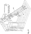
Figure 1 . Basically it includes anelongated inlet vessel 10 having alower outlet end 12 and anupper inlet end 14. Positioned withininlet vessel 10 is anelectrode 16 that provides an electrostatic field through which inlet liquid, identified inFigure 1 as "feed", flows. InFigure 1 electrode 16, shown in dotted outline, is positioned withinvessel 10 in which thevessel 10 is of conductive material, that is metal, so that the electrostatic field is established betweenelectrode 16 and the wall ofvessel 10. -
Inlet vessel 10 is elongated, that is, it has a length measured from theupper inlet end 14 to thelower outlet end 12 that is a multiple of the largest vessel cross-sectional dimension. In the illustrated arrangement ofFigure 1 theinlet vessel 10 is in the form of a pipe, that is, a vessel that, in cross-section, is round. The length ofvessel 10 should preferably be about twice the vessel diameter, however the precise length is not a critical aspect except that it is important that thevessel 10 be elongated so that fluid flowing therethrough is exposed for a minimum length of time to the electrostatic field established byelectrode 16. - A second basic element of the apparatus of
Figure 1 is aseparation vessel 18.Vessel 18 has an upperoil outlet end 20 and a lowerwater outlet end 22. Further,separation vessel 18 has anintermediate inlet passageway 24 that communicates with the inlet vessellower outlet end 12. - As illustrated in
Figure 1 , an inlet flange fitting 26 is secured to the upper inlet end ofinlet vessel 10 and a similar outlet flange fitting 28 is secured to the upperoil outlet end 20 ofseparation vessel 18.Flange fittings Figure 1 to piping but are not otherwise involved in the performance of the system. In like manner, the lower water outlet end 22 ofseparation vessel 18 is provided with a pipe fitting 30 by which water separated by the system may be carried away for disposal or further treatment. - As revealed in
Figure 1 , a mixture of oil and water, designated as "feed" enters the system by way of inlet flange fitting 26 where it passes intoinlet vessel 10. The mixture flows through the elongated inlet vessel that is preferably downwardly sloped as indicated. Sloping the inlet vessel helps allow a high liquid flux past the electrodes. Within the inlet vessel the mixture is exposed to an electrostatic field. Ifelectrode 16 within the inlet vessel is covered with insulation then electricity is not directly conducted from theelectrode 16 to the mixture but instead only an electrostatic field is maintained withinvessel 10 to which the mixture is exposed. By the use of aninsulated electrode 16 the voltage between the electrode and the wall ofvessel 10 can be significant so that an electrostatic field is applied to the inlet mixture. The electrostatic field causes water droplets within the mixture to rapidly coalesce. The mixture, with a significant portion of the water therein coalesced into large droplets immediately passes directly intoseparator vessel 18 that preferably is at an angle perpendicular to the longitudinal axis ofinlet vessel 10. InFigure 1 the longitudinal axis ofinlet vessel 10 is indicated by the numeral 32 while the longitudinal axis ofseparation vessel 18 is indicated by the numeral 34. - The mixture having been subjected to an electrostatic field and therefore having passed through an environment in which the water is rapidly coalesced enters perpendicularly into
separation vessel 18. Withinseparation vessel 18 the inwardly flowing mixture is offered an immediate opportunity to separate into heavier and lighter components. The heavier component separates from the mixture and flows downwardly within the slopedseparation vessel 18 into awater collection portion 36 which is the portion ofvessel 18 belowinlet passageway 24. Water withinwater collection portion 36 is maintained at a selectedlevel 38 by means of awater level control 40. Thewater level control 40 is illustrated diagrammatically since such devices are frequently and customarily used in oil/water separation and are well known to any practitioner in the art. A typical water level control system is illustrated in and will subsequently be described with reference toFigure 8 . Basically, thewater level control 40 operates a valve (not seen) connected to the pipe fitting 30 to drain water as it accumulates within the vessellower portion 36 so that thelevel 38 stays at a pre-selected height withinwater collection portion 36. - The mixture flowing out of
inlet vessel 10 throughlower outlet end 12 separates and the lighter component is carried upwardly into anoil collection portion 42 ofseparation vessel 18. The oil component of the feed mixture having at least a substantial portion of the water extracted therefrom flows through upperoil outlet end 20 ofinlet vessel 10 and through outlet flange fitting 28 for transportation to a pipeline where it may be moved to a refinery, or is conveyed to a facility for storage or further processing. - The system for separating water from a water-in-oil mixture of
Figure 1 is of ultimate simplicity compared to most oil/water separation equipment in use today and yet is arranged to provide improved performance. Specifically, a unique aspect of the separation system ofFigure 1 is that an oil/water mixture is subjected to an electrostatic field and immediately thereafter passes for separation with the water component flowing in one direction and the oil component flowing in an opposite direction. Further, the sloped arrangements ofinlet vessel 10 andseparation vessel 18 provide immediate gravity-assisted separation of a water-in-oil mixture after exposure to an electrostatic field. The apparatus ofFigure 1 provides the most immediate and effective separation of oil and water in the simplest possible flow arrangement as compared with other known systems. - In
Figure 1 the rudiments of the method of applying an electrostatic field to the mixture withininlet vessel 10 is illustrated. Avoltage source 44 provides a voltage output betweenconductors Conductor 48 is secured to the sidewall ofinlet vessel 10 whileconductor 46 is fed through aninsulator 50 that extends through the sidewall ofvessel 10 toelectrode 16. Voltage acrossconductors 6,860,979 teaches a dual frequency electrostatic coalescence system that may be applied to the apparatus ofFigure 1 . Such a dual frequency system is better illustrated and will be discussed with reference toFigure 6 . - The basic system illustrated in
Figure 1 is susceptible of a variety of modifications.Figure 2 shows one example of a modification ofFigure 1 in which theinlet vessel 10,lower outlet 12,upper inlet 14, andelectrode 16 all have the same element number and same purpose as described with reference toFigure 1 . - Inlet vessel
lower end 12 is connected in a straight line with awater collection portion 36A that has awater level control 40 to maintain awater level 38 as described with reference toFigure 1 . The lower water outlet end 22 of the water collection portion inFigure 2 connects to theinlet 52 of a watertreatment process vessel 54 that is illustrative of any system that provides for treating and/or disposing of water extracted from the inlet mixture. Thewater treatment process 54 may include simply a disposal of the water extracted from the inlet water/oil mixture or it may represent further treatment to remove any residuary oil carried over from the inlet mixture, such as a hydrocyclone, a centrifugal force separator, a gravity separator, a corrugated plate separator, a flotation cell or a filter. - In the arrangement of
Figure 2 the inlet mixture flowing into the system throughinlet flange 26 is subjected to an electric field provided byelectrode 16 that functions to cause the water portion of the inlet mixture to coalesce. The coalesced water continues to flow downwardly intowater collection portion 36A. Oil that separates out of the mixture and therefore that remains above thewater level 38 turns upwardly and flows intooil collection portion 42A. Separated oil flows out of thecollection portion 42A through upperoil outlet end 20 and through anoil outlet 56 into an oil treatment process area indicated byvessel 58. Oiltreatment process vessel 58 is emblematic of any system for further handling, transports, treatment or storage of oil separated by the system ofFigure 2 . Typically theoil treatment process 58 can be a storage facility where crude oil having a substantial portion of the water extracted therefrom is stored prior to being transported for further use, such as to a refinery for processing. - Comparing
Figure 2 withFigure 1 shows two distinct differences. First,Figure 2 illustrates watertreatment process vessel 54 andoil treatment vessel 58 as emblematic of further treatment of separated oil and water exiting from the systems. Second,Figure 2 compared toFigure 1 shows a different geometrical arrangement of the flow paths of oil and water that have been separated from an inlet oil-in-water mixture. In bothFigure 1 andFigure 2 separated oil changes directions and moves upwardly at an angle relative to the flow path of the inlet mixture. However, inFigure 2 , compared toFigure 1 , separated water continues in the same flow path of the inlet vessel. Irrespective of these differences the basic function of the systems ofFigures 1 and2 is the same. That is, an inlet mixture of oil-in-water flows in a downward direction through an elongated inlet vessel during which time it is subjected to an electrostatic field and a separation vessel has an inlet passageway in communication with the inlet vessel lower outlet end.Figure 2 shows an arrangement wherein an inlet mixture of oil-in-water is subject to an electrostatic field and immediately thereafter separate passageways are provided by which the separated water and oil flows in different directions. -
Figure 3 shows another alternate system. InFigure 3 inlet vessel 10 is elongated and downwardly sloped, the same as shown inFigures 1 and2 . However, inFigure 3 theoil collection portion 42B is vertically upward. Thelongitudinal axis 32 intersects the separation vessellongitudinal axis 34 at an angle of about 45°. InFigure 3 the mixture after having passed through the electrostatic field established byelectrode 16 withininlet vessel 10 turns and enters horizontally intooil collection portion 42B that is in vertical alignment withwater collection portion 36B. Separated water from the mixture coalesced by action of theelectrode 16 immediately turns downwardly into thewater collection portion 36B and the separated lighter oil component immediately turns upwardly intooil collection portion 42B and flows outupper oil outlet 20. Thus as withFigures 1 and2 , the inlet mixture is subjected to an electrostatic field and immediately thereafter the flow from the inlet mixture enters a divergent path in which separated water can flow in a direction divergent from the separated oil. In the case ofFigure 3 the separated water component immediately diverges into a downward path intowater collection portion 36B while the separated oil component flows in the opposite direction, that is, upwardly intooil collection portion 42. Thus,Figure 3 provides the same unique concept asFigures 1 and2 , that is, a mixture inlet through an elongated vessel in which the mixture is subject to an electrostatic field followed immediately by divergent flow pathways for the separated water and oil components. -
Figure 9 shows another alternate system. Theinlet vessel 10,lower outlet 12,upper inlet 14, andelectrode 16 all have the same element number and same purpose as described with reference toFigures 1 ,2 and 3 .Inlet vessel 10 is elongated and downwardly sloped but with flange fitting 26 oriented to receive a vertical feed. Both thewater collection portion 36C and theoil collection portion 42C of theseparator vessel 18 are aligned along the separation vessellongitudinal axis 34 and oriented at an angle of about 22.5° relative to the horizontal. The inlet vessellongitudinal axis 32 is perpendicular to the separation vessellongitudinal axis 34. The mixture separates, after having passed through the electrostatic field established byelectrode 16 withininlet vessel 10, and the separated water turns angularly downward into thewater collection portion 36C and the separated lighter oil component turns angularly upward into theoil collection portion 42C and flows outupper oil outlet 20. The outlet flange fitting 28 is oriented such that it can connect to a vertically oriented oil treatment process area. Thus as withFigures 1 ,2 and 3 the inlet mixture is subjected to an electrostatic field and immediately thereafter the flow from the inlet mixture enters a divergent path in which separated water can flow in a direction divergent from the separated oil. As suggested byFigures 1 ,2 ,3 and9 , the angle ofinlet vessel 10 can range from 0° to 45° relative to vertical and the angle of theseparation vessel 18 can range from 0° to 45° relative to horizontal. -
Figures 1 ,2 ,3 and9 each make use of plural electrostatic fields. In each ofFigures 1 ,2 ,3 and9 , in addition toelectrode 16 positioned within theinlet vessel 10, asecond electrode 60 is positioned within theoil collection portion 42, that is, there is asecond electrode 60 withinoil collection portion 42 ofFigure 1 , withinoil collection 42A ofFigure 2 , withinoil collection 42B ofFigure 3 , and withinoil collection 42C ofFigure 9 . Each of the second electrodes provide electrostatic fields in the same way as theprimary electrode 16 in each embodiment and serves to further aid in the coalescence of any water remaining in the separated oil after first separation has taken place. Thesecondary electrodes 60 may be insulated or if the percentage of water remaining in the mixture within the oil collection portion of the apparatus has diminished sufficiently then thesecondary electrodes 60 may be bare electrodes operating at lower voltages. -
Figure 4 shows how the basic separation system may be used in series to more completely separate water from a water-in-oil mixture.Figure 4 shows aninlet manifold 62 by which a water-in-oil mixture is fed into a first separation system generally indicated by the numeral 64 that has the components with the same numerical identification asFigure 1 .Outlet flange 28 offirst separation system 64 connects to aninlet flange 26A of asecond separation system 66. Theoutlet flange 28A ofseparation system 66 communicates with anoutlet manifold 68 whereby the oil component of the mixture that flows ininlet manifold 62 is collected. Thus thefirst separation system 64 andsecond separation system 66 each function identically as has been described with reference toFigure 1 in that each has aninlet vessel 10, awater collection portion 36 and anoil collection portion 42. Each inlet vessel has anelectrode 16 and eachwater collection portion 36 has a pipe fitting by which water separated from the feed mixture is conveyed away from the separation system. Further, there is asecond electrode 60 in bothseparation systems - One difference in
Figure 4 compared toFigure 1 is that a gas outlet is illustrated in communication with each of theinlet vessels gas outlet -
Figure 7 is a diagrammatic illustration of how the separation system ofFigure 2 can be connected in series.Figure 7 diagrammatically shows aseparation system 74 that functions as illustrated and described with reference toFigure 2 andidentical separation systems - Referring back to
Figure 4 , this view suggests that the separation systems can easily be placed in parallel.Figure 4 shows twoseparation systems inlet manifold 62 to anoutlet manifold 68. It is easy to see that any number of the systems illustrated inFigure 4 can be placed side-by-side, in parallel, each extending frominlet manifold 62 tooutlet manifold 68. In like manner the system ofFigure 7 could easily be placed in parallel with as many separation systems as required according to the volume of a water-in-oil mixture to be treated. -
Figure 5 illustrates how a separation system may be employed in a desalter system. InFigure 5 afirst separation system 64 as is described with reference toFigure 1 functions to provide separated oil at outlet flange fitting 28 that is connected to a T-fitting 80 having awash water inlet 82. The separated oil flowing fromoutlet flange 28 mixes with wash water in T-fitting 80, and the mixture passes out of the T-fitting throughoutlet 84, through a mixingvalve 86 and through aninlet 88 pipe to adesalter vessel 90. In vessel 90 a quiet zone is provided allowing the oil and water to separate. The water introduced throughwash water inlet 82 absorbs salt content in the oil discharged fromfirst separator system 64. Fromdesalter vessel 90 water passes out throughoutlet 92 and oil having substantially all the water and substantially all the salt removed therefrom flows out throughoil outlet 94. - The basic concepts of the desalter of
Figure 5 are known, that is the step of using wash water to mix with oil having salt therein is known. The significance ofFigure 5 is that it shows how aseparation system 64 can be used in a desalter to improve the efficiency and effectiveness of the desalter system. -
Figure 6 shows a further illustration of how the separation systems may be used in a desalting arrangement. Afirst separation system 64, as illustrated and described with reference toFigure 1 , provides separated oil throughoutlet flange 24 into a T-fitting 80 having awater inlet 82 as described inFigure 5 . The mixture passes through mixingvalve 86 as described and into another inlet flange fitting 26 of asecond separation system 66 that again is the same as the basic separation system ofFigure 1 . The separated oil flowing through outlet fitting 28A enters adesalter vessel 90 where the water and oil components of the mixture separate by gravitation with the water having dissolved salt therein and relatively salt-free oil passing upwardly and out of the desalter throughoil outlet 94. -
Figure 6 shows more details of circuitry by which a voltage may be applied to an electrode within a separation system to which reference will be made subsequently. -
Figure 8 shows one way in which separation systems can be added in series. InFigure 8 an oil/water mixture enters through aninlet 96 into apreliminary separator 98 that is in the form of a vertical vessel having agas outlet 100 at the top. Liquid passes downwardly inpreliminary separator 98 with easily separated water component settling to the bottom into awater level 38 maintained by awater level control 40. Thecontrol 40 operates awater discharge valve 102 so that thelevel 38 is maintained withinvessel 98. A pipe outlet fitting 30 provides for conveying water away frompreliminary separator 98. The mixture having gas and easily separated water removed therefrom flows into afirst separator system 74 like that described inFigure 2 . - As water is separated from the oil content of the mixture within
separation system 74 it flows downwardly intowater collection portion 36A and ultimately is drained out pipe outlet fitting 30. Oil from the mixture moves upwardly throughoil collection portion 42 where it is again exposed to an electrostatic field bysecond electrode 60. The separated oil moves throughoil outlet 56 and into asecond separation system 64 and through downwardlyinclined inlet vessel 10 having anelectrode 16 therein. In theseparation system 64 the mixture is treated as has been described with reference toFigure 1 , that is, in a basic separation system. Frominlet vessel 10, the mixture, after being subjected to the electrostatic field provided byelectrode 16, flows intoseparation vessel 18, the water being channeled downwardly into thewater collection portion 36 where it mixes with water draining out ofwater collection portions 36A ofseparation system 74 and passes out of the system through apipe outlet 30. The oil passing out ofinlet vessel 10 is channeled upwardly throughoil collection portion 42 and out through outlet flange fitting 28, all in the manner as described with reference toFigure 1 . -
Figure 8 is an illustration of how the separation system lends itself to a variety of combinations, all achieved with the basic concepts as revealed inFigure 1 . In the system ofFigure 8 the mixture is subjected to electrostatic field provided by four (4) electrodes. To achieve highly effective separation of water from the oil contained in the mixture, the strength of the electrostatic field of successive electrodes can be increased since each is in a portion of the system wherein the water content of the mixture has been reduced. As an example, whileelectrodes separation system 74 may be insulated,electrodes separation system 64 may be uninsulated, that is bare. Additionally, as shown byFigures 10, 11 and 12 , different electrode configurations may be used forelectrodes Figure 10 electrodes 16A are in the form of parallel plates. InFigure 11 the electrodes 16B are in the form of concentric cylindrical members 16B, while inFigure 12 a coaxial electrode 16C is in the shape of a rod surrounded by a concentric cylindrical member 16D.Second electrode 60 may have any of the cross-sectional arrangements shown inFigures 10, 11 and 12 . - As mentioned with reference to
Figure 1 , each of the electrodes employed in the separation systems described herein is supplied by a voltage potential which may be an AC voltage, a DC voltage, a rectified AC voltage or an AC voltage having selected frequencies and wave forms. An effective voltage format for use with the electrostatic separator systems is a dual frequency voltage as described in detail in United States Patent No.6,860,979 entitled "Dual Frequency Electrostatic Coalescence."Figure 6 shows a basic circuit revealed in this patent by which a dual frequency voltage is applied toelectrode 16 ofseparation system 64. In this dual frequency circuit a three-phase voltage source 104 is applied to arectifier 106 to produce a voltage on aDC bus 108. Voltage fromDC bus 108 supplies amodulator 110 that, by signals fed onconductors 112, controls achopper 114 that provides an AC voltage of selectable frequency to the primary 116 of atransformer 118. The secondary 120 oftransformer 118 applies voltage betweenground 122 and aconductor 124 that supply voltage passing throughinsulator 50 toelectrode 16. The circuit ofFigure 6 provides a method of augmenting the separation of the oil and water components of a mixture flowing throughinlet vessel 10 by providing an AC voltage source of a readily selectable frequency F1 that is modulated in intensity at a selected frequency F2. -
Figure 13 illustrates an alternate as compared to the basic prior art example ofFigure 1 . InFigure 13 ahorizontal transition vessel 126, typically in the form, as illustrated, of a length of pipe, interconnectsoil collection vessel 42 withinlet vessel 10. A tee fitting 128, extends from the bottom ofhorizontal transition vessel 126 and connects to the inlet ofwater collection vessel 36. Thus water separating ininlet vessel 10 andoil collection vessel 42 settles to the bottom ofhorizontal transition vessel 126 and drains out through tee fitting 128 intowater collection vessel 36 while encountering reduced turbulence. - In the drawings the basic configurations of the separator are illustrated in
Figures 1 ,2 ,3 ,9 and13 . Different systems by which this separator system can be applied are illustrated inFigures 4 ,5 ,6 ,7 and8 .Figures 5 and6 illustrate specifically how the separator system herein can be employed in a desalting system in which wash water is utilized. It is important to emphasize that the illustrations of how the separator system can be modified into various configurations, as exemplified inFigures 4 through 8 , are examples only and by no means are illustrated as the only arrangements by which the separator system can be employed. - Referring now to
Figure 14 which represents the claimed invention, afirst separation vessel 130 and asecond separation vessel 132 are arranged one above the other, eachvessel 130 being an upflow leg or stage that has thewet oil inlet 14 located below theelectrode 16 but above the water level control 40 (and therefore above the water level 38). The orientation of thevessels Figures 15 to 15B ) relative to one another. A vertical orientation has logistical advantages and a horizontal orientation has fluid flow advantages. Varying between the two orientations blends the advantages of both orientations. - As the wet oil enters through
inlet 14 of thefirst vessel 130 below theelectrode 16, the wet oil is substantially immediately affected by the electric field. The largest water droplets coalesce and flow downward into thewater collection portion 26 before the wet oil encounters theelectrode 16. The angle of thevessel 130 relative to horizontal (see e.g.,Figure 15 ) allows the expedited countercurrent removal of the coalesced water to thewater collection portion 26. As the drier oil flows upward to theoil collection portion 42 of thevessel 130, smaller water droplets coalesce and separate into the countercurrent flow. The drier oil passes from theoutlet 20 of thefirst vessel 130 and enters theinlet 14 ofsecond vessel 132 below theelectrode 16, where the above separation process is repeated. Eachvessel gas outlet 70 by which gas separated from the system can be carried away, such as to a gas collection facility, a flare or so forth. - A plurality of
baffles 134 that are arranged parallel to one another may be provided in thewater collection portion 26 of eachvessel baffles 134, which are preferably oriented parallel to the axis of thevessel Figures 19 to 21 ). A vertical baffle decreases the Reynolds Number and, therefore, system turbulence. A horizontal baffle decreases the Reynolds Number and settling distance. However, a horizontal configuration increases the number of surfaces on which sand may accumulate. Additionally, the separated oil droplets must cross the water flow in order to travel upward and recombine with the continuous oil phase. An angled baffle-that is, a baffle oriented between 0 and 90 degrees-has the potential to combine the advantages of vertical and horizontal baffles, providing shorter settling distances and an increased angle of repose for the sand. The separated oil droplets cross the water flow at the wall where flow velocity is a minimum. - As illustrated in
Figures 16 ,18 , and24A & B a degasser orpretreatment unit 136 may be connected to theinlet 14 of thefirst separator vessel 130. Pretreatment prevents excessive gas from entering into vessel 130 (and 132) and reduces the inlet water volume by initiating water removal. In a preferred embodiment, thepretreatment unit 136 is a PORTA-TEST WHIRLYSCRUB® V™ vertical centrifugal separator (Cameron Corp. Process Systems, formerly National Tank Company Corp., Houston, Texas) or CONSEPT ICD™ centrifugal separator (also Cameron Corp. Process Systems, formerly National Tank Company Corp., Houston, Texas). The tangential inlet on these particular centrifugal separators promotes free-gas removal and initiates free-water coalescence by creating a high-g environment. As illustrated inFigures 24A & B ,pretreatment unit 136 may include awater collection portion 138. - Experiments by the inventors on various configurations of a compact electrostatic separator made according to this invention have provided insights into what works best. Different performance characteristics depend on whether the oil-water flow is upward or downward. For example, the oil-water flow in the arrangement of
Figures 24A & B is a downward flow in each of the separator vessels, 130, 132 (with thepretreatment unit 136 andvessels Figure 24B and controlled by a single level control). With respect to inlet water fraction, for high water fractions (about 30-70% BS&W), up flow yields superior results whereas for moderate water fractions (about 5-10% BS&W) down flow performs better. With respect to outlet water fractions, the up flow configuration has a limit on the amount of water that can be removed. The drag of the upward flowing oil prevents small amounts of water from falling into thewater collection portion 36 of thevessel - With respect to the electrostatic technique, AC is the only appropriate technique in up flow configurations given very wet oil inlet flows. Furthermore, the
electrode 16 is preferably a bare electrode when the wet oil has a high water fraction. Because the flow coming into a down flow configuration is moderately wet, there is a possibility to use AC as well as dual polarity and dual frequency techniques to achieve very dry outlet oils. As discussed previously in connection withFigure 6 , an effective voltage format for use with the electrostatic separator systems of this invention is a dual frequency voltage as described in detail in United States Patent No.6,860,979 entitled "Dual Frequency Electrostatic Coalescence" and incorporated herein by reference. The moderately wet inflow also provides an opportunity to use aninsulated electrode 16. - Referring now to
Figures 22 and23 , a compact electrostatic separator is illustrated that combines the most advantageous features of an up flow and a down flow configuration. Wet oil enters theinlet 14 of afirst separator vessel 130, which is in an up flow configuration, below theelectrode 16 and above thewater level control 40. Because of the high water fraction of the wet oil,first stage electrode 16 is a bare electrode used in combination with AC technology.Electrode 16 causes water droplets to coalesce and fall out of the oil-water mixture into thewater collection portion 36. Because of the high density of the water relative to the oil and its low viscosity, most of the water can fall out of the mixture into thewater collection portion 36. However, at some point, the drag force of the upwardly moving oil-water mixture exceeds the remaining water's ability to move downward. With much of the water exiting the lower water outlet end 22 of thefirst vessel 130, a moderately dry oil exits the upperoil outlet end 20 ofvessel 130 and enters theinlet 14 to asecond separator vessel 132, which is in a down flow configuration. - The moderately dry oil enters the
second vessel 132 about even with theelectrode 60.Second stage electrode 60 performs the same function as that of thefirst stage electrode 16.Electrode 60 may be an insulated electrode and used in combination with AC or with dual polarity and dual frequency techniques. With the momentum of the water and the mixture being in the same direction, the drag on the oil-water mixture is reduced and much more of the remaining water can fall out into thewater collection portion 36 of thesecond vessel 132. This water exits at the lowerwater outlet end 22 and nearly dry oil exits from the upperoil outlet end 20. Note that because upperoil outlet end 20 of thefirst vessel 130 and theinlet 14 of thesecond vessel 132 are both at the upper ends of thevessels Figures 14 and15 . - Laboratory studies demonstrate that the addition for reactance to the transformer 118 (see
Figure 6 ) is beneficial. From preliminary lab data, when the reactance is absorbing about 5 to 70% of the input voltage, it is performing two functions. First, it limits both the number and length of arcing short circuits. This tends to increase the applied voltage on theelectrode 16 and produce more coalescence. Second, the voltage adjustments caused by the arc response induce a voltage modulation. This voltage modulation enhances the coalescence of water droplets of varying size, which leads to improved separation. The combination of these two properties improves the quality of both the oil and water (see Tables 1 and 2).Table 1. Effect of Added Reactance on the Quality of Oil and Water. 2000 Volts 1st Electrode; 5000 Volts 2nd Electrode ∼100 °F 2000 B/D psf, 32-34% H2OAmps 1st Amps 2nd Added Reactance MHY % H2O Dry Oil Out Angle of Baffle PPM Oil 1st Water Outlet % Oil 2nd Water Outlet 1.4 0.4 0 5.6* 0 160 36* 1.4 0.4 0 5.6* 45 179 36* 1.4 0.4 0 5.6* 90 261 36* 0.5 0.4 35 5.2 45 58 1.7 0.5 0.4 47 5.6 45 123 2.7 0.5 0.4 59 5.5 45 120 2.3 0.6† 0.6 59 4.9 45 94 0.5 * Values averaged † One sample only 3000 Volts and 7500 Volts Table 2. Effect of Added Reactance and No Baffles in the Second Separator Vessel on the Quality of Oil and Water. ∼100 °F 2000 B/D psf, 32-34% H2O Amps 1st KVoltage In/Out Amps 2nd KVoltage In/Out Added Reactance MHY % H2O Dry Oil Out Angle of Baffle PPM Oil 1st Water Outlet Baffled PPM Oil 2nd Water Outlet Not Baffled 0.6 4.0/1.7 0.6 8.0/7.6 56 5 45 49 10K 0.6 4.0/1.7 0.9 9.1/8.2 56 4.6 45 57 5K 0.6 4.0/1.7 1.3 11.0/9.1 56 4.3 45 51 220 - Referring now to
Figures 25 and26 , an additional oil outlet 20a is provided that routes oil dry enough to meet a user's requirements on adry oil path 142 that bypasses thesecond separator vessel 132. InFigure 25 , wet oil (about 30-70% H2O) entersinlet 14(1) of thefirst separator vessel 130 and dry oil (about < 1% H2O) exits at the top end of thevessel 130 through outlet 20a. The balance of the medium-wet or moderately dry oil (about 5-10% H2O) exitsoutlet 20B and enters theinlet 14(2) of thesecond separator vessel 132. Dry oil then exits thesecond vessel 132 throughoutlet 20D and alongdry oil path 142. Preferably, the flow throughoutlet 20A is controlled to ensure that any oil that exceeds the user's requirements is not routed through the outlet 20A (thereby bypassing the second vessel 132). The same holds true foroutlet 20D. - In
Figure 26 , thefirst separator vessel 130, which is an up flow vessel, includes twoadditional outlets outlet 20B is located in close proximity to thewet oil inlet 14. As wet oil passes throughinlet 14(1) and enters thefirst separator vessel 130, a portion of the wet oil is diverted tooutlet 20B and intoinlet 14(2) of thesecond separator vessel 132, which is also an up flow vessel. Dry oil that meets the user's requirements exits throughadditional outlet 20A located at the top end ofvessel 130 and travels alongpath 142. - The
second separator vessel 132 converts the wet oil from thefirst vessel 130 to a medium-wet oil, which exits thesecond vessel 132 throughoutlet 20D and travels along medium-wet oil path 144 to theinlet 14(3B) of an additional orthird separator vessel 140. Vessel 240 is a down flow vessel substantially similar in structure to that ofvessels Figures 24A & B . Medium- or moderately wet oil which passes throughoutlet 20C of thefirst vessel 130 also travels along medium-wet oil path 144 to theinlet 14(3A) of athird vessel 140. Dry oil then exits throughoutlet 20E of thethird vessel 140 and travels alongdry oil path 142.
Claims (19)
- An apparatus for separating water from a water-and-oil mixture, comprising:a first (130) and a second (132) elongated separator vessel, each said first and second elongated separator vessel having at its upper end an oil collection portion (42) including an electrode (16) and at its lower end a water collection portion (36) including a water level control (40) ;and,each said first (130) and second (132) elongated separator vessel having an inlet (14) located below the electrode and above the water level control (40) and an oil outlet (20), the electrode (16) being arranged to subject a water-and-oil mixture exiting the inlet (14) and entering the elongated separator vessel subject to an electric field, the inlet to the second elongated separator vessel being the oil outlet of the first elongated separator vessel, the inlet arranged to provide a predetermined direction of flow within the elongated separator vessel of a water-and-oil mixture entering the elongated separator vessel;wherein each first (130) and second (132) elongated separator vessel further comprises a water outlet (22) at its lower end configured to carry away water that has been separated by the system from the water-and-oil mixture; andwherein longitudinal axes of the first (130) and second (132) elongated separator vessels are parallel to each other and oriented at an incline relative to a horizontal plane and the oil outlet (20) of the first elongated separator vessel is directly coupled to the inlet of the second elongated separator vessel by a short connection from the oil outlet at the oil collection portion of the first separator vessel to the inlet of the second separator vessel;and further wherein the electrodes are only located in each elongated separator vessel and each elongated separator vessel has only one electrode portion.
- An apparatus according to Claim 1, said first elongated separator is at a different elevation than that of said second elongated separator vessel.
- An apparatus according to Claim 1, the predetermined flow direction within said first elongated separator vessel is different than that within said second elongated separator vessel.
- An apparatus according to Claim 1 further comprising the electrode in at least one of said first and second elongated separator vessels being in circuit relationship to an AC voltage source.
- An apparatus according to Claim 1 further comprising a first and a second voltage source, the electrode in said first elongated separator vessel being in circuit relationship to the first voltage source, the electrode in said second elongated separator vessel being in circuit relationship to the second voltage source, the first voltage source being at lower potential than the second voltage source.
- An apparatus according to Claim 1 further comprising a voltage source in circuit relationship to at least one of the electrodes includes reactance provided by a transformer.
- An apparatus according to Claim 1 further comprising the electrode in said first elongated separator vessel being a different type of electrode than the electrode in said second elongated separator vessel.
- An apparatus according to Claim 1 further comprising at least one of said first and second elongated separator vessels including a plurality of baffles arranged parallel to one another in the lower water collection portion of the elongated separator vessel.
- An apparatus according to Claim 8 further comprising each baffle in said plurality of baffles being a baffle selected from the group consisting of a horizontal baffle, a vertical baffle, and an angled baffle.
- An apparatus according to Claim 1 further comprising a degasser unit connected to the inlet of said first elongated separator vessel.
- A method of separating water from a water-and-oil mixture using the apparatus of claim 1, the method comprising the steps of:(a) flowing a water-and-oil mixture into an inlet of a first elongated separator vessel;(b) passing the water-and-oil mixture through an electric field of the first elongated separator vessel whereby water in the water-and-oil mixture coalesces and a first water predominant fluid flows downward;(c) flowing a portion of a first oil predominant fluid out of the outlet of the first elongated separator vessel and into the inlet of a second elongated separator vessel; and(d) passing the portion of the first oil predominant fluid through an electric field of the second elongated separator vessel whereby water in the portion of the first oil predominant fluid coalesces and a second water predominant fluid flows downward.
- A method according to Claim 11, the predetermined direction of flow being a direction of flow selected from the group consisting of an upward direction of flow and a downward direction of flow.
- A method according to Claim 11 further comprising the step of:(e) allowing a second portion of the first oil predominant fluid to exit the outlet of the first elongated separator vessel and bypass the second elongated separator vessel.
- A method according to Claim 11 further comprising the steps of:(f) after said step (a), allowing a portion of the water-and-oil mixture to substantially immediately exit the outlet of the first elongated separator vessel and flow into the inlet of an additional elongated separator vessel, the additional elongated separator vessel being oriented on an incline and having an electrode located toward its upper end and an inlet located below the electrode and an oil outlet having a portion location opposite a lower end of the electrode, and electrode being arranged to subject a water-and-oil mixture exiting the inlet and entering the additional elongated separator vessel to an electric field, the inlet to the additional elongated separator vessel being the oil outlet of the first elongated separator vessel, the inlet arranged relative to the additional elongated separator vessel to provide a predetermined direction of flow within the additional elongated separator vessel of a water-and-oil mixture entering the additional elongated separator vessel; and(g) passing the portion of the water-and-oil mixture through an electric field of the additional elongated separator vessel whereby water in the portion of the water-and-oil mixture coalesces and a third water predominant fluid flows downward.
- A method according to Claim 14, wherein predetermined direction of flow of the water-and-oil mixture as the water-and-oil mixture enters the additional elongated separator vessel being a direction of flow selected from the group consisting of an upward direction of flow and a downward direction of flow.
- A method according to Claim 15 further comprising the step of:(h) flowing a portion of a third oil predominant fluid out of the outlet of the additional elongated separator vessel and into the inlet of the second elongated separator vessel.
- A method according to Claim 11 further comprising the step of flowing the water-and-oil mixture to a pre-separation unit prior to said step (a).
- A method according to Claim 11, at least one of the first water predominant flow and the second water predominant flow passes through a plurality of baffles.
- A method according to Claim 11, the electrode of the first and second elongated separator vessels is each in circuit relationship to a voltage source at a different potential than the other voltage source.
Priority Applications (1)
| Application Number | Priority Date | Filing Date | Title |
|---|---|---|---|
| EP18204461.0A EP3513854B1 (en) | 2012-06-08 | 2013-06-07 | High velocity electrostatic coalescing oil/water separator |
Applications Claiming Priority (2)
| Application Number | Priority Date | Filing Date | Title |
|---|---|---|---|
| US13/491,890 US9095790B2 (en) | 2012-06-08 | 2012-06-08 | High velocity electrostatic coalescing oil/water separator |
| PCT/US2013/044727 WO2013185040A1 (en) | 2012-06-08 | 2013-06-07 | High velocity electrostatic coalescing oil/water separator |
Related Child Applications (1)
| Application Number | Title | Priority Date | Filing Date |
|---|---|---|---|
| EP18204461.0A Division EP3513854B1 (en) | 2012-06-08 | 2013-06-07 | High velocity electrostatic coalescing oil/water separator |
Publications (2)
| Publication Number | Publication Date |
|---|---|
| EP2858732A1 EP2858732A1 (en) | 2015-04-15 |
| EP2858732B1 true EP2858732B1 (en) | 2018-11-14 |
Family
ID=48626700
Family Applications (2)
| Application Number | Title | Priority Date | Filing Date |
|---|---|---|---|
| EP18204461.0A Active EP3513854B1 (en) | 2012-06-08 | 2013-06-07 | High velocity electrostatic coalescing oil/water separator |
| EP13729236.3A Active EP2858732B1 (en) | 2012-06-08 | 2013-06-07 | High velocity electrostatic coalescing oil/water separator |
Family Applications Before (1)
| Application Number | Title | Priority Date | Filing Date |
|---|---|---|---|
| EP18204461.0A Active EP3513854B1 (en) | 2012-06-08 | 2013-06-07 | High velocity electrostatic coalescing oil/water separator |
Country Status (6)
| Country | Link |
|---|---|
| US (1) | US9095790B2 (en) |
| EP (2) | EP3513854B1 (en) |
| BR (1) | BR112014030008A2 (en) |
| CA (1) | CA2875203A1 (en) |
| MX (1) | MX360277B (en) |
| WO (1) | WO2013185040A1 (en) |
Families Citing this family (11)
| Publication number | Priority date | Publication date | Assignee | Title |
|---|---|---|---|---|
| US10870592B2 (en) | 2015-05-15 | 2020-12-22 | Onesubsea Ip Uk Limited | Electrostatic separator |
| US9957446B2 (en) | 2015-12-22 | 2018-05-01 | Cameron Solutions, Inc. | Topside oil production equipment system for reduction in space and weight |
| US9957447B2 (en) | 2015-12-22 | 2018-05-01 | Cameron Solutions, Inc. | Electrostatic technology system and process to dehydrate crude oil in a crude oil storage tank of a floating production storage and offloading installation |
| US9914073B2 (en) | 2015-12-22 | 2018-03-13 | Cameron Solutions, Inc. | Crude oil storage tank with electrostatic internals to dehydrate crude oil within a process train of a floating production storage and offloading installation |
| BR112019017625B1 (en) | 2017-02-27 | 2023-02-07 | Fmc Separation Systems Bv | SEPARATOR |
| US11034893B2 (en) | 2018-01-09 | 2021-06-15 | Saudi Arabian Oil Company | Desalting plant systems and methods for enhanced tight emulsion crude oil treatment |
| US10513663B2 (en) | 2018-01-09 | 2019-12-24 | Saudi Arabian Oil Company | Gas oil separation plant systems and methods for rag layer treatment |
| US11794132B2 (en) * | 2019-07-18 | 2023-10-24 | Cameron International Corporation | Digital treatment of multi-phase liquid mixtures |
| GB2589558A (en) * | 2019-10-23 | 2021-06-09 | Equinor Energy As | Separator |
| US11491418B2 (en) | 2019-11-27 | 2022-11-08 | Saudi Arabian Oil Company | Floating assembly of inclined channels with an applied electrical field for the accelerated electrostatic separation of water-in-oil dispersions |
| CN112322344B (en) * | 2020-10-22 | 2022-09-09 | 青岛理工大学 | Pipe network type rod electrode squirrel-cage array type three-stage degassing and dewatering device |
Family Cites Families (47)
| Publication number | Priority date | Publication date | Assignee | Title |
|---|---|---|---|---|
| US1116299A (en) | 1914-07-22 | 1914-11-03 | Robert E Laird | Process of treating petroleum emulsions. |
| US1276387A (en) | 1918-01-22 | 1918-08-20 | Charles W Mckibben | Method of separating associated liquids. |
| US1838931A (en) | 1927-09-03 | 1931-12-29 | Petroleum Rectifying Co | Apparatus for converting commercial frequency circuits into high frequency circuits |
| US2120932A (en) | 1933-05-15 | 1938-06-14 | Union Oil Co | High frequency induction dehydrator |
| US2849395A (en) | 1953-09-29 | 1958-08-26 | Research Corp | Method and apparatus for electrical separation of emulsions |
| US2825686A (en) | 1953-10-29 | 1958-03-04 | Exxon Research Engineering Co | Electrical coalescence process |
| US3148134A (en) | 1960-07-11 | 1964-09-08 | Petrolite Corp | Electric treater for dispersions |
| US3597346A (en) | 1969-05-07 | 1971-08-03 | Petrolite Corp | Inclined,electric wet-oil treater |
| US3839176A (en) | 1971-03-08 | 1974-10-01 | North American Rockwell | Method and apparatus for removing contaminants from liquids |
| US3847775A (en) | 1971-11-10 | 1974-11-12 | Combustion Eng | Process for electrical coalescing of water |
| US3772180A (en) | 1971-11-10 | 1973-11-13 | Combustion Eng | Electric treater |
| US4283290A (en) | 1977-07-06 | 1981-08-11 | Davy International (Oil & Chemicals) Ltd. | Purification utilizing liquid membrane with electrostatic coalescence |
| US4126537A (en) | 1977-07-15 | 1978-11-21 | Combustion Engineering, Inc. | Method and apparatus for separation of fluids with an electric field |
| US4161439A (en) | 1978-04-03 | 1979-07-17 | Combustion Engineering, Inc. | Apparatus for application of electrostatic fields to mixing and separating fluids |
| US4204934A (en) | 1978-04-03 | 1980-05-27 | Combustion Engineering, Inc. | Process for application of electrostatic fields to mixing and separating fluids |
| US4200516A (en) | 1978-07-28 | 1980-04-29 | Combustion Engineering, Inc. | Electrostatic coalescing system |
| US4290882A (en) | 1978-12-21 | 1981-09-22 | Davy Powergas Inc. | Electrostatic separation of impurities phase from liquid-liquid extraction |
| US4224124A (en) | 1979-08-30 | 1980-09-23 | Combustion Engineering, Inc. | Electrostatic coalescing system |
| US4308127A (en) | 1980-03-17 | 1981-12-29 | Combustion Engineering, Inc. | Separation of emulsions with electric field |
| US4415426A (en) | 1980-09-30 | 1983-11-15 | Exxon Research And Engineering Co. | Electrodes for electrical coalescense of liquid emulsions |
| DE3176445D1 (en) | 1980-11-01 | 1987-10-22 | Univ Bradford | Settling of liquid dispersions |
| US4417971A (en) | 1981-11-30 | 1983-11-29 | Combustion Engineering, Inc. | Circuit for maintaining the strength of an electrostatic field generated in a fluid mixture of varying dielectric strength |
| US4469582A (en) | 1982-03-22 | 1984-09-04 | Combustion Engineering, Inc. | Electrically enhanced inclined plate separator |
| US4804453A (en) | 1982-06-07 | 1989-02-14 | National Tank Company | Resolution of emulsions with multiple electric fields |
| WO1993012856A1 (en) | 1982-09-30 | 1993-07-08 | Floyd Leon Prestridge | Voltage control system for electrostatic oil treater |
| US4479161A (en) | 1982-09-27 | 1984-10-23 | The Bendix Corporation | Switching type driver circuit for fuel injector |
| GB8413734D0 (en) | 1984-05-30 | 1984-07-04 | Shell Int Research | Separating dispersed liquid phase from continuous liquid phase |
| US4581120A (en) | 1984-09-19 | 1986-04-08 | Combustion Engineering, Inc. | Method and apparatus for separating oilfield emulsions |
| EP0211953A1 (en) | 1985-03-09 | 1987-03-04 | University Of Bradford | Liquid-liquid contacting |
| US4606801A (en) | 1985-07-16 | 1986-08-19 | Combustion Engineering, Inc. | Electrostatic mixer/separator |
| US4702815A (en) | 1986-05-05 | 1987-10-27 | National Tank Company | Distributed charge composition electrodes and desalting system |
| US4767515A (en) | 1987-07-30 | 1988-08-30 | The United States Of America As Represented By The United States Department Of Energy | Surface area generation and droplet size control in solvent extraction systems utilizing high intensity electric fields |
| US5147045A (en) | 1988-11-28 | 1992-09-15 | Exportech Company, Inc. | Particulate separations by electrostatic coalescence |
| US5824203A (en) | 1992-02-10 | 1998-10-20 | Sgi International | Method and means for changing characteristics of substances |
| US5421972A (en) | 1992-10-19 | 1995-06-06 | National Tank Company & Catalytic Distillation Technologies | Process and apparatus for removing soluble contaminants from hydrocarbon streams |
| US5464522A (en) | 1992-11-23 | 1995-11-07 | Edmondson, Jerry M | Electrostatic oil emulsion treating method and apparatus |
| US5411651A (en) | 1993-03-01 | 1995-05-02 | National Tank Company | Method for electrostatic liquid/liquid contactor |
| FR2702671B1 (en) * | 1993-03-15 | 1995-05-05 | Inst Francais Du Petrole | Device and method for separating phases of different densities and conductivities by electrocoalescence and centrifugation. |
| US5575896A (en) | 1994-04-06 | 1996-11-19 | National Tank Company | Method and apparatus for oil/water separation using a dual electrode centrifugal coalescer |
| US5565078A (en) | 1994-04-06 | 1996-10-15 | National Tank Company | Apparatus for augmenting the coalescence of water in a water-in-oil emulsion |
| US6113765A (en) | 1997-10-17 | 2000-09-05 | The Texas A&M University System | Methods for enhanced resolution of hydrocarbon continuous emulsions or dispersions with conductivity modifiers |
| US6010634A (en) | 1998-02-18 | 2000-01-04 | National Tank Company | System and method for separating mingled heavier and lighter components of a liquid stream |
| US6136174A (en) | 1998-06-03 | 2000-10-24 | Kvaerner Process Systems | Compact electrostatic coalescer |
| PL351182A1 (en) | 2001-12-13 | 2003-06-16 | Abb Sp Zoo | Electrostatic separator |
| US6860979B2 (en) | 2002-08-07 | 2005-03-01 | National Tank Company | Dual frequency electrostatic coalescence |
| US7157007B2 (en) | 2003-06-20 | 2007-01-02 | National Tank Company | Vertical gas induced flotation cell |
| US8591714B2 (en) * | 2007-04-17 | 2013-11-26 | National Tank Company | High velocity electrostatic coalescing oil/water separator |
-
2012
- 2012-06-08 US US13/491,890 patent/US9095790B2/en active Active
-
2013
- 2013-06-07 MX MX2014015027A patent/MX360277B/en active IP Right Grant
- 2013-06-07 CA CA2875203A patent/CA2875203A1/en not_active Abandoned
- 2013-06-07 BR BR112014030008A patent/BR112014030008A2/en not_active Application Discontinuation
- 2013-06-07 WO PCT/US2013/044727 patent/WO2013185040A1/en active Application Filing
- 2013-06-07 EP EP18204461.0A patent/EP3513854B1/en active Active
- 2013-06-07 EP EP13729236.3A patent/EP2858732B1/en active Active
Non-Patent Citations (1)
| Title |
|---|
| None * |
Also Published As
| Publication number | Publication date |
|---|---|
| CA2875203A1 (en) | 2013-12-12 |
| EP2858732A1 (en) | 2015-04-15 |
| US9095790B2 (en) | 2015-08-04 |
| US20130327646A1 (en) | 2013-12-12 |
| BR112014030008A2 (en) | 2017-06-27 |
| EP3513854B1 (en) | 2022-04-20 |
| WO2013185040A1 (en) | 2013-12-12 |
| EP3513854A1 (en) | 2019-07-24 |
| MX360277B (en) | 2018-10-25 |
| MX2014015027A (en) | 2015-06-22 |
Similar Documents
| Publication | Publication Date | Title |
|---|---|---|
| EP2858732B1 (en) | High velocity electrostatic coalescing oil/water separator | |
| US9764253B2 (en) | High velocity electrostatic coalescing oil/water separator | |
| US6860979B2 (en) | Dual frequency electrostatic coalescence | |
| US20200080007A1 (en) | Gas oil separation plant systems and methods for rag layer treatment | |
| US10383181B2 (en) | RF heating of a dielectric fluid | |
| CN114164020B (en) | Offshore oilfield crude oil dehydration treatment system and process | |
| US20160097004A1 (en) | Processes for desalting crude oil under dynamic flow conditions | |
| CN106318442A (en) | Sump oil purifying device and method | |
| US5464522A (en) | Electrostatic oil emulsion treating method and apparatus | |
| CN108290084B (en) | High flow electrostatic separator for subsea applications | |
| US10786757B2 (en) | Compact electrocoalescer with conical frustum electrodes | |
| BRPI0810401A2 (en) | high speed electrostatic coalescence oil / water separator | |
| US20110042304A1 (en) | Method And Apparatus To Enhance Separation Performance Of A Lean And Low Mean Size Dispersed Phase From A Continuous Phase |
Legal Events
| Date | Code | Title | Description |
|---|---|---|---|
| PUAI | Public reference made under article 153(3) epc to a published international application that has entered the european phase |
Free format text: ORIGINAL CODE: 0009012 |
|
| 17P | Request for examination filed |
Effective date: 20141111 |
|
| AK | Designated contracting states |
Kind code of ref document: A1 Designated state(s): AL AT BE BG CH CY CZ DE DK EE ES FI FR GB GR HR HU IE IS IT LI LT LU LV MC MK MT NL NO PL PT RO RS SE SI SK SM TR |
|
| AX | Request for extension of the european patent |
Extension state: BA ME |
|
| DAX | Request for extension of the european patent (deleted) | ||
| 17Q | First examination report despatched |
Effective date: 20160406 |
|
| STAA | Information on the status of an ep patent application or granted ep patent |
Free format text: STATUS: EXAMINATION IS IN PROGRESS |
|
| GRAP | Despatch of communication of intention to grant a patent |
Free format text: ORIGINAL CODE: EPIDOSNIGR1 |
|
| STAA | Information on the status of an ep patent application or granted ep patent |
Free format text: STATUS: GRANT OF PATENT IS INTENDED |
|
| INTG | Intention to grant announced |
Effective date: 20180530 |
|
| GRAS | Grant fee paid |
Free format text: ORIGINAL CODE: EPIDOSNIGR3 |
|
| GRAA | (expected) grant |
Free format text: ORIGINAL CODE: 0009210 |
|
| STAA | Information on the status of an ep patent application or granted ep patent |
Free format text: STATUS: THE PATENT HAS BEEN GRANTED |
|
| AK | Designated contracting states |
Kind code of ref document: B1 Designated state(s): AL AT BE BG CH CY CZ DE DK EE ES FI FR GB GR HR HU IE IS IT LI LT LU LV MC MK MT NL NO PL PT RO RS SE SI SK SM TR |
|
| REG | Reference to a national code |
Ref country code: CH Ref legal event code: EP Ref country code: AT Ref legal event code: REF Ref document number: 1064134 Country of ref document: AT Kind code of ref document: T Effective date: 20181115 |
|
| REG | Reference to a national code |
Ref country code: DE Ref legal event code: R096 Ref document number: 602013046662 Country of ref document: DE |
|
| REG | Reference to a national code |
Ref country code: IE Ref legal event code: FG4D |
|
| REG | Reference to a national code |
Ref country code: LT Ref legal event code: MG4D |
|
| REG | Reference to a national code |
Ref country code: NL Ref legal event code: FP |
|
| REG | Reference to a national code |
Ref country code: AT Ref legal event code: MK05 Ref document number: 1064134 Country of ref document: AT Kind code of ref document: T Effective date: 20181114 |
|
| PG25 | Lapsed in a contracting state [announced via postgrant information from national office to epo] |
Ref country code: IS Free format text: LAPSE BECAUSE OF FAILURE TO SUBMIT A TRANSLATION OF THE DESCRIPTION OR TO PAY THE FEE WITHIN THE PRESCRIBED TIME-LIMIT Effective date: 20190314 Ref country code: FI Free format text: LAPSE BECAUSE OF FAILURE TO SUBMIT A TRANSLATION OF THE DESCRIPTION OR TO PAY THE FEE WITHIN THE PRESCRIBED TIME-LIMIT Effective date: 20181114 Ref country code: BG Free format text: LAPSE BECAUSE OF FAILURE TO SUBMIT A TRANSLATION OF THE DESCRIPTION OR TO PAY THE FEE WITHIN THE PRESCRIBED TIME-LIMIT Effective date: 20190214 Ref country code: HR Free format text: LAPSE BECAUSE OF FAILURE TO SUBMIT A TRANSLATION OF THE DESCRIPTION OR TO PAY THE FEE WITHIN THE PRESCRIBED TIME-LIMIT Effective date: 20181114 Ref country code: LV Free format text: LAPSE BECAUSE OF FAILURE TO SUBMIT A TRANSLATION OF THE DESCRIPTION OR TO PAY THE FEE WITHIN THE PRESCRIBED TIME-LIMIT Effective date: 20181114 Ref country code: ES Free format text: LAPSE BECAUSE OF FAILURE TO SUBMIT A TRANSLATION OF THE DESCRIPTION OR TO PAY THE FEE WITHIN THE PRESCRIBED TIME-LIMIT Effective date: 20181114 Ref country code: LT Free format text: LAPSE BECAUSE OF FAILURE TO SUBMIT A TRANSLATION OF THE DESCRIPTION OR TO PAY THE FEE WITHIN THE PRESCRIBED TIME-LIMIT Effective date: 20181114 Ref country code: AT Free format text: LAPSE BECAUSE OF FAILURE TO SUBMIT A TRANSLATION OF THE DESCRIPTION OR TO PAY THE FEE WITHIN THE PRESCRIBED TIME-LIMIT Effective date: 20181114 |
|
| REG | Reference to a national code |
Ref country code: NO Ref legal event code: T2 Effective date: 20181114 |
|
| PG25 | Lapsed in a contracting state [announced via postgrant information from national office to epo] |
Ref country code: PT Free format text: LAPSE BECAUSE OF FAILURE TO SUBMIT A TRANSLATION OF THE DESCRIPTION OR TO PAY THE FEE WITHIN THE PRESCRIBED TIME-LIMIT Effective date: 20190314 Ref country code: GR Free format text: LAPSE BECAUSE OF FAILURE TO SUBMIT A TRANSLATION OF THE DESCRIPTION OR TO PAY THE FEE WITHIN THE PRESCRIBED TIME-LIMIT Effective date: 20190215 Ref country code: RS Free format text: LAPSE BECAUSE OF FAILURE TO SUBMIT A TRANSLATION OF THE DESCRIPTION OR TO PAY THE FEE WITHIN THE PRESCRIBED TIME-LIMIT Effective date: 20181114 Ref country code: AL Free format text: LAPSE BECAUSE OF FAILURE TO SUBMIT A TRANSLATION OF THE DESCRIPTION OR TO PAY THE FEE WITHIN THE PRESCRIBED TIME-LIMIT Effective date: 20181114 Ref country code: SE Free format text: LAPSE BECAUSE OF FAILURE TO SUBMIT A TRANSLATION OF THE DESCRIPTION OR TO PAY THE FEE WITHIN THE PRESCRIBED TIME-LIMIT Effective date: 20181114 |
|
| PG25 | Lapsed in a contracting state [announced via postgrant information from national office to epo] |
Ref country code: IT Free format text: LAPSE BECAUSE OF FAILURE TO SUBMIT A TRANSLATION OF THE DESCRIPTION OR TO PAY THE FEE WITHIN THE PRESCRIBED TIME-LIMIT Effective date: 20181114 Ref country code: CZ Free format text: LAPSE BECAUSE OF FAILURE TO SUBMIT A TRANSLATION OF THE DESCRIPTION OR TO PAY THE FEE WITHIN THE PRESCRIBED TIME-LIMIT Effective date: 20181114 Ref country code: DK Free format text: LAPSE BECAUSE OF FAILURE TO SUBMIT A TRANSLATION OF THE DESCRIPTION OR TO PAY THE FEE WITHIN THE PRESCRIBED TIME-LIMIT Effective date: 20181114 Ref country code: PL Free format text: LAPSE BECAUSE OF FAILURE TO SUBMIT A TRANSLATION OF THE DESCRIPTION OR TO PAY THE FEE WITHIN THE PRESCRIBED TIME-LIMIT Effective date: 20181114 |
|
| REG | Reference to a national code |
Ref country code: DE Ref legal event code: R097 Ref document number: 602013046662 Country of ref document: DE |
|
| PG25 | Lapsed in a contracting state [announced via postgrant information from national office to epo] |
Ref country code: SK Free format text: LAPSE BECAUSE OF FAILURE TO SUBMIT A TRANSLATION OF THE DESCRIPTION OR TO PAY THE FEE WITHIN THE PRESCRIBED TIME-LIMIT Effective date: 20181114 Ref country code: SM Free format text: LAPSE BECAUSE OF FAILURE TO SUBMIT A TRANSLATION OF THE DESCRIPTION OR TO PAY THE FEE WITHIN THE PRESCRIBED TIME-LIMIT Effective date: 20181114 Ref country code: EE Free format text: LAPSE BECAUSE OF FAILURE TO SUBMIT A TRANSLATION OF THE DESCRIPTION OR TO PAY THE FEE WITHIN THE PRESCRIBED TIME-LIMIT Effective date: 20181114 Ref country code: RO Free format text: LAPSE BECAUSE OF FAILURE TO SUBMIT A TRANSLATION OF THE DESCRIPTION OR TO PAY THE FEE WITHIN THE PRESCRIBED TIME-LIMIT Effective date: 20181114 |
|
| PLBE | No opposition filed within time limit |
Free format text: ORIGINAL CODE: 0009261 |
|
| STAA | Information on the status of an ep patent application or granted ep patent |
Free format text: STATUS: NO OPPOSITION FILED WITHIN TIME LIMIT |
|
| REG | Reference to a national code |
Ref country code: NO Ref legal event code: CHAD Owner name: CAMERON TECHNOLOGIES LIMITED, NL |
|
| 26N | No opposition filed |
Effective date: 20190815 |
|
| PG25 | Lapsed in a contracting state [announced via postgrant information from national office to epo] |
Ref country code: SI Free format text: LAPSE BECAUSE OF FAILURE TO SUBMIT A TRANSLATION OF THE DESCRIPTION OR TO PAY THE FEE WITHIN THE PRESCRIBED TIME-LIMIT Effective date: 20181114 |
|
| REG | Reference to a national code |
Ref country code: DE Ref legal event code: R119 Ref document number: 602013046662 Country of ref document: DE |
|
| PG25 | Lapsed in a contracting state [announced via postgrant information from national office to epo] |
Ref country code: MC Free format text: LAPSE BECAUSE OF FAILURE TO SUBMIT A TRANSLATION OF THE DESCRIPTION OR TO PAY THE FEE WITHIN THE PRESCRIBED TIME-LIMIT Effective date: 20181114 |
|
| REG | Reference to a national code |
Ref country code: CH Ref legal event code: PL |
|
| REG | Reference to a national code |
Ref country code: NL Ref legal event code: PD Owner name: CAMERON TECHNOLOGIES LIMITED; IE Free format text: DETAILS ASSIGNMENT: CHANGE OF OWNER(S), ASSIGNMENT; FORMER OWNER NAME: CAMERON INTERNATIONAL CORPORATION Effective date: 20200221 |
|
| REG | Reference to a national code |
Ref country code: GB Ref legal event code: 732E Free format text: REGISTERED BETWEEN 20200220 AND 20200226 |
|
| REG | Reference to a national code |
Ref country code: BE Ref legal event code: MM Effective date: 20190630 |
|
| PG25 | Lapsed in a contracting state [announced via postgrant information from national office to epo] |
Ref country code: TR Free format text: LAPSE BECAUSE OF FAILURE TO SUBMIT A TRANSLATION OF THE DESCRIPTION OR TO PAY THE FEE WITHIN THE PRESCRIBED TIME-LIMIT Effective date: 20181114 |
|
| PG25 | Lapsed in a contracting state [announced via postgrant information from national office to epo] |
Ref country code: IE Free format text: LAPSE BECAUSE OF NON-PAYMENT OF DUE FEES Effective date: 20190607 Ref country code: DE Free format text: LAPSE BECAUSE OF NON-PAYMENT OF DUE FEES Effective date: 20200101 |
|
| PG25 | Lapsed in a contracting state [announced via postgrant information from national office to epo] |
Ref country code: LU Free format text: LAPSE BECAUSE OF NON-PAYMENT OF DUE FEES Effective date: 20190607 Ref country code: BE Free format text: LAPSE BECAUSE OF NON-PAYMENT OF DUE FEES Effective date: 20190630 Ref country code: CH Free format text: LAPSE BECAUSE OF NON-PAYMENT OF DUE FEES Effective date: 20190630 Ref country code: LI Free format text: LAPSE BECAUSE OF NON-PAYMENT OF DUE FEES Effective date: 20190630 |
|
| PG25 | Lapsed in a contracting state [announced via postgrant information from national office to epo] |
Ref country code: FR Free format text: LAPSE BECAUSE OF NON-PAYMENT OF DUE FEES Effective date: 20190630 |
|
| PG25 | Lapsed in a contracting state [announced via postgrant information from national office to epo] |
Ref country code: CY Free format text: LAPSE BECAUSE OF FAILURE TO SUBMIT A TRANSLATION OF THE DESCRIPTION OR TO PAY THE FEE WITHIN THE PRESCRIBED TIME-LIMIT Effective date: 20181114 |
|
| PG25 | Lapsed in a contracting state [announced via postgrant information from national office to epo] |
Ref country code: MT Free format text: LAPSE BECAUSE OF FAILURE TO SUBMIT A TRANSLATION OF THE DESCRIPTION OR TO PAY THE FEE WITHIN THE PRESCRIBED TIME-LIMIT Effective date: 20181114 Ref country code: HU Free format text: LAPSE BECAUSE OF FAILURE TO SUBMIT A TRANSLATION OF THE DESCRIPTION OR TO PAY THE FEE WITHIN THE PRESCRIBED TIME-LIMIT; INVALID AB INITIO Effective date: 20130607 |
|
| PG25 | Lapsed in a contracting state [announced via postgrant information from national office to epo] |
Ref country code: MK Free format text: LAPSE BECAUSE OF FAILURE TO SUBMIT A TRANSLATION OF THE DESCRIPTION OR TO PAY THE FEE WITHIN THE PRESCRIBED TIME-LIMIT Effective date: 20181114 |
|
| P01 | Opt-out of the competence of the unified patent court (upc) registered |
Effective date: 20231208 |
|
| PGFP | Annual fee paid to national office [announced via postgrant information from national office to epo] |
Ref country code: NL Payment date: 20240415 Year of fee payment: 12 |
|
| PGFP | Annual fee paid to national office [announced via postgrant information from national office to epo] |
Ref country code: NO Payment date: 20240222 Year of fee payment: 12 |
|
| PGFP | Annual fee paid to national office [announced via postgrant information from national office to epo] |
Ref country code: GB Payment date: 20240402 Year of fee payment: 12 |