EP2858546B1 - A rack suitable for using in dishwashers and the dishwasher wherein the rack is used - Google Patents
A rack suitable for using in dishwashers and the dishwasher wherein the rack is used Download PDFInfo
- Publication number
- EP2858546B1 EP2858546B1 EP13726230.9A EP13726230A EP2858546B1 EP 2858546 B1 EP2858546 B1 EP 2858546B1 EP 13726230 A EP13726230 A EP 13726230A EP 2858546 B1 EP2858546 B1 EP 2858546B1
- Authority
- EP
- European Patent Office
- Prior art keywords
- rack
- shaft
- carrier
- carriers
- objects
- Prior art date
- Legal status (The legal status is an assumption and is not a legal conclusion. Google has not performed a legal analysis and makes no representation as to the accuracy of the status listed.)
- Not-in-force
Links
Images
Classifications
-
- A—HUMAN NECESSITIES
- A47—FURNITURE; DOMESTIC ARTICLES OR APPLIANCES; COFFEE MILLS; SPICE MILLS; SUCTION CLEANERS IN GENERAL
- A47L—DOMESTIC WASHING OR CLEANING; SUCTION CLEANERS IN GENERAL
- A47L15/00—Washing or rinsing machines for crockery or tableware
- A47L15/42—Details
- A47L15/50—Racks ; Baskets
- A47L15/502—Cutlery baskets
Definitions
- the present invention relates to a rack comprising an accessory whereon the objects to be washed are placed and the dishwasher wherein the rack is used.
- cutlery baskets are used that provide the small volume objects to be washed.
- the cutlery basket cannot be entirely filled or is not used, the part of the cutlery basket that remains empty occupies unnecessary space inside the dishwasher and prevent loading of the other objects.
- an additional washing unit is needed for washing the objects like forks and spoons.
- European Patent Application EP2283765 discloses a dishwasher rack comprising a shaft with a vertical axis and one carrier mounted on the shaft, whereon cutlery objects can be placed.
- the aim of the present invention is the realization of a rack comprising an accessory which allows effective usage of the inner volume, and of a dishwasher wherein the rack is used.
- the rack that is suitable for using in dishwashers, realized in order to attain the aim of the present invention and explicated in the claims, comprises an accessory having a shaft which extends in the vertical axis and more than one carrier which is mounted onto the shaft so as to rotate around the shaft and whereon the objects such as forks, spoons, etc. are placed.
- the useable area of the accessory can be expanded and narrowed in the horizontal plane.
- the loading area narrows and as the carriers move away from each other, the loading area widens.
- the loading area is provided to be widened or narrowed according to the need when desired.
- the horizontal and vertical axes of the carriers are aligned at the same level, the area of only one carrier can be used.
- the accessory is kept inside the rack so as to allow the space of maximum one carrier to be used or is removed from the rack completely.
- the carrier and the adjacent carrier are mounted onto the shaft one above the other so as to overlap with each other.
- the shaft provides the carriers to be held together in the same vertical direction and determines the rotational axis of the accessory.
- the carrier has a first position wherein it is positioned almost one above the other with at least one other carrier and a second position wherein, by being rotated around the shaft, it is brought almost side by side with another carrier such that the objects can be placed on the carrier. While some of the carriers are in the first position, some of them can be kept in the second position. Thus, a sufficient number of carriers are brought to the second position to provide a sufficient area whereon only the objects to be washed are placed and the unused carriers are prevented from occupying unnecessary space on the rack by being kept in the first position.
- the shaft is disposed on the side wall of the rack.
- the accessory occupies less space inside the rack.
- the shaft extends upwards from the base of the rack.
- the carriers are positioned on the shaft at a height that allows the objects to be placed in the space remaining below the carriers.
- the carrier comprises at least one housing providing the carrier to be mounted onto the shaft.
- the carrier can be easily mounted onto the shaft.
- the housing is shaped so as to allow the carrier to rotate around the shaft.
- At least one hole, wherein the objects like forks and spoons are placed, is located on the carrier.
- the holes may have different cross-sectional areas in order to facilitate the placement of the objects in different sizes.
- At least two carriers overlap so that the objects can be placed in one hole on each carrier when the carriers are one above the other.
- the objects can be placed onto the carriers that almost completely overlap.
- the carrier comprises at least one protrusion-shaped stopper.
- the protrusion-shaped stopper on the carrier provides the next carrier to stop by bearing against the edge thereof.
- the rack comprises a support whereon the shaft is mounted.
- the support provides the carriers to be mounted to the rack in a more balanced manner.
- connection member providing the support to be mounted to the rack is disposed on the support.
- the support can be removed from the rack and can be mounted to the rack again when needed by means of the connection member.
- the accessory is fan-shaped.
- the carriers are shaped as triangles narrowing towards the housing.
- the rack volume is provided to be used effectively by an accessory used for placing the objects like forks and spoons.
- the utilization space of the accessory (4) can be increased and decreased as needed.
- the unused carriers (2) are prevented from occupying unnecessary space on the rack (1).
- the carriers (2) are mounted onto the shaft (3) one above the other so as to at least partially overlap.
- the carriers (2) are held together in the same vertical direction. Furthermore, the carriers (2) can move over each other easily by being rotated around the shaft (3).
- the carrier (2) has a first position wherein it is positioned almost one above the other with at least one other carrier (2) and a second position wherein it is brought almost side by side with the other carriers (2) by being rotated around the shaft (3) and the objects like forks and spoons are placed thereon. According to the need a desired number of carriers (2) are brought to the second position and the unused carriers (2) are kept in the first position in order to provide efficient utilization of the rack (1) volume.
- the shaft (3) is disposed on the side wall of the rack (1).
- the carriers (2) mounted to the shaft (3) occupy less space on the rack (1) and the rack (1) volume is utilized efficiently.
- the shaft (3) extends upwards from the base of the rack (1).
- the objects to be washed can also be placed in the space remaining below the carriers (2) mounted to the shaft (3).
- the carrier (2) comprises at least one housing (5) providing the carrier (2) to be mounted onto the shaft (3).
- the housing (5) bears the shaft (3).
- the carrier (2) comprises at least one hole (6) wherein the objects like forks and spoons are placed.
- the holes (6) are shaped so as to allow the objects to be washed to be easily placed and removed.
- At least two holes (6) overlap so as to allow the objects to be placed therein when at least two carriers (2) overlap.
- the objects can be placed onto the carriers (2) that almost completely overlap.
- the carrier (2) comprises at least one protrusion-shaped stopper (7) that stops another carrier (2).
- the protrusion-shaped stopper (7) on the carrier (2) provides the next carrier (2) to stop by bearing against the edge of the carrier (2).
- the rack (1) comprises a support (8) situated on the rack (1) and whereon the shaft (3) is mounted.
- the support (8) provides the shaft (3) and hence the carriers (2) carried by the shaft (3) to be mounted to the rack (1) in a more balanced manner.
- the support (8) comprises at least one connection member (9) providing the support (8) to be mounted onto the rack (1).
- the connection member (9) provides the support (8) to be easily mounted to/dismounted from the rack (1).
- the accessory (4) is fan-shaped.
- the carrier (2) is triangle-shaped.
- an accessory (4) is obtained that is used for placing the objects like forks and spoons into the dishwasher and that provides the user with loading spaces with variable sizes.
Description
- The present invention relates to a rack comprising an accessory whereon the objects to be washed are placed and the dishwasher wherein the rack is used.
- In dishwashers, cutlery baskets are used that provide the small volume objects to be washed. When the cutlery basket cannot be entirely filled or is not used, the part of the cutlery basket that remains empty occupies unnecessary space inside the dishwasher and prevent loading of the other objects. When the cutlery basket volume is not sufficient, an additional washing unit is needed for washing the objects like forks and spoons.
- In the state of the art International Patent Application No.
WO2011154386 , a cutlery basket is described which provides variable storage space by means of the storing units that move with respect to each other. - European Patent Application
EP2283765 discloses a dishwasher rack comprising a shaft with a vertical axis and one carrier mounted on the shaft, whereon cutlery objects can be placed. - The aim of the present invention is the realization of a rack comprising an accessory which allows effective usage of the inner volume, and of a dishwasher wherein the rack is used.
- The rack that is suitable for using in dishwashers, realized in order to attain the aim of the present invention and explicated in the claims, comprises an accessory having a shaft which extends in the vertical axis and more than one carrier which is mounted onto the shaft so as to rotate around the shaft and whereon the objects such as forks, spoons, etc. are placed.
- By means of the carriers moving by rotating around the shaft in the vertical axis, the useable area of the accessory can be expanded and narrowed in the horizontal plane. As the carriers move closer to each other, the loading area narrows and as the carriers move away from each other, the loading area widens. Thus, the loading area is provided to be widened or narrowed according to the need when desired. When the horizontal and vertical axes of the carriers are aligned at the same level, the area of only one carrier can be used. When not in use, the accessory is kept inside the rack so as to allow the space of maximum one carrier to be used or is removed from the rack completely.
- In an embodiment of the present invention, the carrier and the adjacent carrier are mounted onto the shaft one above the other so as to overlap with each other. The shaft provides the carriers to be held together in the same vertical direction and determines the rotational axis of the accessory.
- In an embodiment of the present invention, the carrier has a first position wherein it is positioned almost one above the other with at least one other carrier and a second position wherein, by being rotated around the shaft, it is brought almost side by side with another carrier such that the objects can be placed on the carrier. While some of the carriers are in the first position, some of them can be kept in the second position. Thus, a sufficient number of carriers are brought to the second position to provide a sufficient area whereon only the objects to be washed are placed and the unused carriers are prevented from occupying unnecessary space on the rack by being kept in the first position.
- In an embodiment of the present invention, the shaft is disposed on the side wall of the rack. Thus, the accessory occupies less space inside the rack.
- In an embodiment of the present invention, the shaft extends upwards from the base of the rack. The carriers are positioned on the shaft at a height that allows the objects to be placed in the space remaining below the carriers.
- In an embodiment of the present invention, the carrier comprises at least one housing providing the carrier to be mounted onto the shaft. Thus, the carrier can be easily mounted onto the shaft. The housing is shaped so as to allow the carrier to rotate around the shaft.
- In an embodiment of the present invention, at least one hole, wherein the objects like forks and spoons are placed, is located on the carrier. The holes may have different cross-sectional areas in order to facilitate the placement of the objects in different sizes.
- In an embodiment of the present invention, at least two carriers overlap so that the objects can be placed in one hole on each carrier when the carriers are one above the other. Thus, the objects can be placed onto the carriers that almost completely overlap.
- In an embodiment of the present invention, the carrier comprises at least one protrusion-shaped stopper. The protrusion-shaped stopper on the carrier provides the next carrier to stop by bearing against the edge thereof.
- In an embodiment of the present invention, the rack comprises a support whereon the shaft is mounted. The support provides the carriers to be mounted to the rack in a more balanced manner.
- In an embodiment of the present invention, at least one connection member providing the support to be mounted to the rack is disposed on the support. When the accessory is not in use, the support can be removed from the rack and can be mounted to the rack again when needed by means of the connection member.
- In an embodiment of the present invention, the accessory is fan-shaped.
- In an embodiment of the present invention, the carriers are shaped as triangles narrowing towards the housing.
- By means of the present invention, the rack volume is provided to be used effectively by an accessory used for placing the objects like forks and spoons.
- The model embodiments relating to the rack and the dishwasher, realized in order to attain the aim of the present invention, are illustrated in the attached figures, where:
-
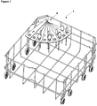
Figure 1 - is the perspective view of a rack and an accessory wherein the objects are placed in an embodiment of the present invention. -
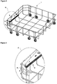
Figure 2 - is the perspective view of a rack and an accessory in an embodiment of the present invention. -
Figure 3 - is the view of detail A inFigure 2 . -
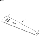
Figure 4 - is the top perspective view of the carrier in an embodiment of the present invention. - The elements illustrated in the figures are numbered as follows:
- 1. Rack
- 2. Carrier
- 3. Shaft
- 4. Accessory
- 5. Housing
- 6. Hole
- 7. Stopper
- 8. Support
- 9. Connection member
- The rack (1) of the present invention that is suitable for using in dishwashers comprises an accessory (4) having a shaft (3) which extends in the vertical axis and more than one carrier (2) which is mounted onto the shaft (3) so as to rotate around the shaft (3) and whereon the objects like forks and spoons are placed.
- By means of the carriers (2) being rotated around the vertical axis formed by the shaft (3), the utilization space of the accessory (4) can be increased and decreased as needed. By opening only a sufficient number of carriers (2) to provide the area whereon the objects can be placed, the unused carriers (2) are prevented from occupying unnecessary space on the rack (1).
- In an embodiment of the present invention, the carriers (2) are mounted onto the shaft (3) one above the other so as to at least partially overlap. By means of the shaft (3), the carriers (2) are held together in the same vertical direction. Furthermore, the carriers (2) can move over each other easily by being rotated around the shaft (3).
- In an embodiment of the present invention, the carrier (2) has a first position wherein it is positioned almost one above the other with at least one other carrier (2) and a second position wherein it is brought almost side by side with the other carriers (2) by being rotated around the shaft (3) and the objects like forks and spoons are placed thereon. According to the need a desired number of carriers (2) are brought to the second position and the unused carriers (2) are kept in the first position in order to provide efficient utilization of the rack (1) volume.
- In an embodiment of the present invention, the shaft (3) is disposed on the side wall of the rack (1). Thus, the carriers (2) mounted to the shaft (3) occupy less space on the rack (1) and the rack (1) volume is utilized efficiently.
- In an embodiment of the present invention, the shaft (3) extends upwards from the base of the rack (1). Thus, the objects to be washed can also be placed in the space remaining below the carriers (2) mounted to the shaft (3).
- In an embodiment of the present invention, the carrier (2) comprises at least one housing (5) providing the carrier (2) to be mounted onto the shaft (3). The housing (5) bears the shaft (3).
- In an embodiment of the present invention, the carrier (2) comprises at least one hole (6) wherein the objects like forks and spoons are placed. The holes (6) are shaped so as to allow the objects to be washed to be easily placed and removed.
- In an embodiment of the present invention, at least two holes (6) overlap so as to allow the objects to be placed therein when at least two carriers (2) overlap. Thus, the objects can be placed onto the carriers (2) that almost completely overlap.
- In an embodiment of the present invention, the carrier (2) comprises at least one protrusion-shaped stopper (7) that stops another carrier (2). The protrusion-shaped stopper (7) on the carrier (2) provides the next carrier (2) to stop by bearing against the edge of the carrier (2).
- In an embodiment of the present invention, the rack (1) comprises a support (8) situated on the rack (1) and whereon the shaft (3) is mounted. The support (8) provides the shaft (3) and hence the carriers (2) carried by the shaft (3) to be mounted to the rack (1) in a more balanced manner.
- In an embodiment of the present invention, the support (8) comprises at least one connection member (9) providing the support (8) to be mounted onto the rack (1). The connection member (9) provides the support (8) to be easily mounted to/dismounted from the rack (1).
- In an embodiment of the present invention, the accessory (4) is fan-shaped.
- In an embodiment of the present invention, the carrier (2) is triangle-shaped.
- By means of the present invention, an accessory (4) is obtained that is used for placing the objects like forks and spoons into the dishwasher and that provides the user with loading spaces with variable sizes.
- It is to be understood that the present invention is not limited to the embodiments disclosed above and a person skilled in the art can easily introduce different embodiments. These should be considered within the scope of the protection postulated by the claims of the present invention.
Claims (15)
- A rack (1) that is suitable for using in dishwashers with an accessory (4) comprising a shaft (3) which extends in the vertical axis and characterized by more than one carrier (2) which is mounted onto the shaft (3) so as to rotate around the shaft (3) and whereon objects like forks and spoons can be placed.
- A rack (1) as in Claim 1, characterized by the accessory (4), the utilization space of which can be increased and decreased by means of the carriers (2) being rotated around the vertical axis formed by the shaft (3).
- A rack (1) as in Claim 1 or 2, characterized by the carrier (2) having a first position wherein it is positioned almost one above the other with at least one other carrier (2) and a second position wherein it is brought almost side by side with the other carrier (2) by being rotated around the shaft (3) and the objects like forks and spoons are placed thereon.
- A rack (1) as in any one of the above claims, characterized by a shaft (3) whereon the carriers (2) are mounted one above the other so as to at least partially overlap.
- A rack (1) as in any one of the above claims, characterized by the shaft (3) which is disposed on the side wall of the rack (1).
- A rack (1) as in Claim 4, characterized by the shaft (3) that extends upwards from the base of the rack (1).
- A rack (1) as in any one of the above claims, characterized by the carrier (2) comprising at least one housing (5) that provides the carrier (2) to be mounted onto the shaft (3).
- A rack (1) as in any one of the above claims, characterized by the carrier (2) comprising at least one hole (6) wherein the objects like forks and spoons can be placed.
- A rack (1) as in Claim 8, characterized by the at least two holes (6) which overlap so as to allow the objects to be placed therein when at least two carriers (2) overlap.
- A rack (1) as in any one of the above claims, characterized by the carrier (2) comprising at least one protrusion-shaped stopper (7) that stops the other carriers (2).
- A rack (1) as in any one of the above claims, characterized by a support (8) whereon the shaft (3) is mounted.
- A rack (1) as in Claim 11, characterized by the support (8) comprising at least one connection member (9) that provides the support (8) to be mounted onto the rack (1).
- A rack (1) as in any one of the above claims, characterized in that, the accessory (4) is fan shaped.
- A rack (1) as in any one of the above claims, characterized in that the carrier (2) is triangle shaped.
- A dishwasher comprising a rack (1) as in any one of the above claims.
Applications Claiming Priority (2)
| Application Number | Priority Date | Filing Date | Title |
|---|---|---|---|
| TR201206621 | 2012-06-06 | ||
| PCT/EP2013/061358 WO2013182512A1 (en) | 2012-06-06 | 2013-06-03 | A rack suitable for using in dishwashers and the dishwasher wherein the rack is used |
Publications (2)
| Publication Number | Publication Date |
|---|---|
| EP2858546A1 EP2858546A1 (en) | 2015-04-15 |
| EP2858546B1 true EP2858546B1 (en) | 2016-08-03 |
Family
ID=48539191
Family Applications (1)
| Application Number | Title | Priority Date | Filing Date |
|---|---|---|---|
| EP13726230.9A Not-in-force EP2858546B1 (en) | 2012-06-06 | 2013-06-03 | A rack suitable for using in dishwashers and the dishwasher wherein the rack is used |
Country Status (2)
| Country | Link |
|---|---|
| EP (1) | EP2858546B1 (en) |
| WO (1) | WO2013182512A1 (en) |
Families Citing this family (3)
| Publication number | Priority date | Publication date | Assignee | Title |
|---|---|---|---|---|
| WO2017114554A1 (en) * | 2015-12-29 | 2017-07-06 | Arcelik Anonim Sirketi | A cutlery basket for dishwashers and a dishwasher comprising a cutlery basket |
| US9924851B2 (en) | 2016-02-10 | 2018-03-27 | Haier Us Appliance Solutions, Inc. | Modular dishwasher rack system |
| WO2018069002A1 (en) * | 2016-10-10 | 2018-04-19 | Arcelik Anonim Sirketi | A stemware holder suitable for using in a dishwasher |
Family Cites Families (5)
| Publication number | Priority date | Publication date | Assignee | Title |
|---|---|---|---|---|
| US3779258A (en) * | 1972-02-11 | 1973-12-18 | Whirlpool Co | Rotating silverware basket for dishwasher |
| EP1275336A1 (en) * | 2001-07-11 | 2003-01-15 | Bonferraro S.p.A. | Dishwasher rack with tip-up shelves provided with pull-out cutlery grids |
| EP1281347B1 (en) * | 2001-08-01 | 2007-10-10 | CANDY S.p.A. | Domestic dishwasher machine with an additional cutlery basket. |
| DE102009028035A1 (en) * | 2009-07-27 | 2011-02-03 | BSH Bosch und Siemens Hausgeräte GmbH | Domestic dishwasher |
| WO2011154386A1 (en) | 2010-06-08 | 2011-12-15 | Arcelik Anonim Sirketi | A dishwasher and a cutlery basket used therein |
-
2013
- 2013-06-03 EP EP13726230.9A patent/EP2858546B1/en not_active Not-in-force
- 2013-06-03 WO PCT/EP2013/061358 patent/WO2013182512A1/en active Application Filing
Also Published As
| Publication number | Publication date |
|---|---|
| WO2013182512A1 (en) | 2013-12-12 |
| EP2858546A1 (en) | 2015-04-15 |
Similar Documents
| Publication | Publication Date | Title |
|---|---|---|
| EP2723226B1 (en) | A dishwasher | |
| EP1686883B1 (en) | A basket for dishwashers | |
| CN105249914B (en) | The saucer component of bowl basket of dishwasher and there is its bowl basket of dishwasher | |
| EP2326237B1 (en) | A dishwasher with drawer attached to tub roof | |
| EP3164045B1 (en) | Dishwasher comprising a wire rack with an improved carrier adaptor structure | |
| EP2858546B1 (en) | A rack suitable for using in dishwashers and the dishwasher wherein the rack is used | |
| JP2008073400A (en) | Dish washer | |
| US20120222711A1 (en) | Dishwasher having an adjustable upper basket | |
| WO2013098019A1 (en) | A cutlery basket for dishwashers | |
| EP2600757B1 (en) | Dishwasher | |
| US20130299438A1 (en) | Removable tine block assembly for a dishwashing appliance | |
| US9265402B2 (en) | Dishwasher rack assembly with support for large and small bowls | |
| EP2772181B1 (en) | Dishwasher basket | |
| EP2797484B1 (en) | A rack suitable for using in a dishwasher and the dishwasher wherein the rack is used | |
| US8151810B2 (en) | Basket assembly for a dishwasher, and associated apparatus | |
| US20130300270A1 (en) | Roller assembly for an appliance | |
| EP2473087B1 (en) | A dishwasher rack | |
| WO2015000508A1 (en) | Dishwasher basket | |
| EP2554100B1 (en) | A dishwasher rack comprising a shelf provided with a cover | |
| WO2017114554A1 (en) | A cutlery basket for dishwashers and a dishwasher comprising a cutlery basket | |
| WO2018041553A1 (en) | Glass holder suitable for use in dishwashers | |
| WO2017005424A1 (en) | A dishwasher comprising a cutlery basket | |
| WO2015000507A1 (en) | Tableware supporting insert for a dishwasher basket and dishwasher basket comprising said | |
| WO2017194507A1 (en) | A dishwasher | |
| WO2015101881A1 (en) | Dishwasher and corresponding rack accessory |
Legal Events
| Date | Code | Title | Description |
|---|---|---|---|
| PUAI | Public reference made under article 153(3) epc to a published international application that has entered the european phase |
Free format text: ORIGINAL CODE: 0009012 |
|
| 17P | Request for examination filed |
Effective date: 20141031 |
|
| AK | Designated contracting states |
Kind code of ref document: A1 Designated state(s): AL AT BE BG CH CY CZ DE DK EE ES FI FR GB GR HR HU IE IS IT LI LT LU LV MC MK MT NL NO PL PT RO RS SE SI SK SM TR |
|
| AX | Request for extension of the european patent |
Extension state: BA ME |
|
| DAX | Request for extension of the european patent (deleted) | ||
| GRAP | Despatch of communication of intention to grant a patent |
Free format text: ORIGINAL CODE: EPIDOSNIGR1 |
|
| INTG | Intention to grant announced |
Effective date: 20160322 |
|
| GRAS | Grant fee paid |
Free format text: ORIGINAL CODE: EPIDOSNIGR3 |
|
| GRAA | (expected) grant |
Free format text: ORIGINAL CODE: 0009210 |
|
| AK | Designated contracting states |
Kind code of ref document: B1 Designated state(s): AL AT BE BG CH CY CZ DE DK EE ES FI FR GB GR HR HU IE IS IT LI LT LU LV MC MK MT NL NO PL PT RO RS SE SI SK SM TR |
|
| REG | Reference to a national code |
Ref country code: GB Ref legal event code: FG4D |
|
| REG | Reference to a national code |
Ref country code: CH Ref legal event code: EP Ref country code: AT Ref legal event code: REF Ref document number: 816792 Country of ref document: AT Kind code of ref document: T Effective date: 20160815 |
|
| REG | Reference to a national code |
Ref country code: IE Ref legal event code: FG4D |
|
| REG | Reference to a national code |
Ref country code: DE Ref legal event code: R096 Ref document number: 602013010070 Country of ref document: DE |
|
| REG | Reference to a national code |
Ref country code: NL Ref legal event code: MP Effective date: 20160803 |
|
| REG | Reference to a national code |
Ref country code: LT Ref legal event code: MG4D |
|
| REG | Reference to a national code |
Ref country code: AT Ref legal event code: MK05 Ref document number: 816792 Country of ref document: AT Kind code of ref document: T Effective date: 20160803 |
|
| PG25 | Lapsed in a contracting state [announced via postgrant information from national office to epo] |
Ref country code: NL Free format text: LAPSE BECAUSE OF FAILURE TO SUBMIT A TRANSLATION OF THE DESCRIPTION OR TO PAY THE FEE WITHIN THE PRESCRIBED TIME-LIMIT Effective date: 20160803 Ref country code: RS Free format text: LAPSE BECAUSE OF FAILURE TO SUBMIT A TRANSLATION OF THE DESCRIPTION OR TO PAY THE FEE WITHIN THE PRESCRIBED TIME-LIMIT Effective date: 20160803 Ref country code: IS Free format text: LAPSE BECAUSE OF FAILURE TO SUBMIT A TRANSLATION OF THE DESCRIPTION OR TO PAY THE FEE WITHIN THE PRESCRIBED TIME-LIMIT Effective date: 20161203 Ref country code: LT Free format text: LAPSE BECAUSE OF FAILURE TO SUBMIT A TRANSLATION OF THE DESCRIPTION OR TO PAY THE FEE WITHIN THE PRESCRIBED TIME-LIMIT Effective date: 20160803 Ref country code: IT Free format text: LAPSE BECAUSE OF FAILURE TO SUBMIT A TRANSLATION OF THE DESCRIPTION OR TO PAY THE FEE WITHIN THE PRESCRIBED TIME-LIMIT Effective date: 20160803 Ref country code: FI Free format text: LAPSE BECAUSE OF FAILURE TO SUBMIT A TRANSLATION OF THE DESCRIPTION OR TO PAY THE FEE WITHIN THE PRESCRIBED TIME-LIMIT Effective date: 20160803 Ref country code: HR Free format text: LAPSE BECAUSE OF FAILURE TO SUBMIT A TRANSLATION OF THE DESCRIPTION OR TO PAY THE FEE WITHIN THE PRESCRIBED TIME-LIMIT Effective date: 20160803 Ref country code: NO Free format text: LAPSE BECAUSE OF FAILURE TO SUBMIT A TRANSLATION OF THE DESCRIPTION OR TO PAY THE FEE WITHIN THE PRESCRIBED TIME-LIMIT Effective date: 20161103 |
|
| PG25 | Lapsed in a contracting state [announced via postgrant information from national office to epo] |
Ref country code: PL Free format text: LAPSE BECAUSE OF FAILURE TO SUBMIT A TRANSLATION OF THE DESCRIPTION OR TO PAY THE FEE WITHIN THE PRESCRIBED TIME-LIMIT Effective date: 20160803 Ref country code: ES Free format text: LAPSE BECAUSE OF FAILURE TO SUBMIT A TRANSLATION OF THE DESCRIPTION OR TO PAY THE FEE WITHIN THE PRESCRIBED TIME-LIMIT Effective date: 20160803 Ref country code: SE Free format text: LAPSE BECAUSE OF FAILURE TO SUBMIT A TRANSLATION OF THE DESCRIPTION OR TO PAY THE FEE WITHIN THE PRESCRIBED TIME-LIMIT Effective date: 20160803 Ref country code: AT Free format text: LAPSE BECAUSE OF FAILURE TO SUBMIT A TRANSLATION OF THE DESCRIPTION OR TO PAY THE FEE WITHIN THE PRESCRIBED TIME-LIMIT Effective date: 20160803 Ref country code: PT Free format text: LAPSE BECAUSE OF FAILURE TO SUBMIT A TRANSLATION OF THE DESCRIPTION OR TO PAY THE FEE WITHIN THE PRESCRIBED TIME-LIMIT Effective date: 20161205 Ref country code: GR Free format text: LAPSE BECAUSE OF FAILURE TO SUBMIT A TRANSLATION OF THE DESCRIPTION OR TO PAY THE FEE WITHIN THE PRESCRIBED TIME-LIMIT Effective date: 20161104 Ref country code: LV Free format text: LAPSE BECAUSE OF FAILURE TO SUBMIT A TRANSLATION OF THE DESCRIPTION OR TO PAY THE FEE WITHIN THE PRESCRIBED TIME-LIMIT Effective date: 20160803 |
|
| PG25 | Lapsed in a contracting state [announced via postgrant information from national office to epo] |
Ref country code: RO Free format text: LAPSE BECAUSE OF FAILURE TO SUBMIT A TRANSLATION OF THE DESCRIPTION OR TO PAY THE FEE WITHIN THE PRESCRIBED TIME-LIMIT Effective date: 20160803 Ref country code: EE Free format text: LAPSE BECAUSE OF FAILURE TO SUBMIT A TRANSLATION OF THE DESCRIPTION OR TO PAY THE FEE WITHIN THE PRESCRIBED TIME-LIMIT Effective date: 20160803 |
|
| REG | Reference to a national code |
Ref country code: DE Ref legal event code: R097 Ref document number: 602013010070 Country of ref document: DE |
|
| PG25 | Lapsed in a contracting state [announced via postgrant information from national office to epo] |
Ref country code: SK Free format text: LAPSE BECAUSE OF FAILURE TO SUBMIT A TRANSLATION OF THE DESCRIPTION OR TO PAY THE FEE WITHIN THE PRESCRIBED TIME-LIMIT Effective date: 20160803 Ref country code: CZ Free format text: LAPSE BECAUSE OF FAILURE TO SUBMIT A TRANSLATION OF THE DESCRIPTION OR TO PAY THE FEE WITHIN THE PRESCRIBED TIME-LIMIT Effective date: 20160803 Ref country code: DK Free format text: LAPSE BECAUSE OF FAILURE TO SUBMIT A TRANSLATION OF THE DESCRIPTION OR TO PAY THE FEE WITHIN THE PRESCRIBED TIME-LIMIT Effective date: 20160803 Ref country code: SM Free format text: LAPSE BECAUSE OF FAILURE TO SUBMIT A TRANSLATION OF THE DESCRIPTION OR TO PAY THE FEE WITHIN THE PRESCRIBED TIME-LIMIT Effective date: 20160803 Ref country code: BE Free format text: LAPSE BECAUSE OF FAILURE TO SUBMIT A TRANSLATION OF THE DESCRIPTION OR TO PAY THE FEE WITHIN THE PRESCRIBED TIME-LIMIT Effective date: 20160803 Ref country code: BG Free format text: LAPSE BECAUSE OF FAILURE TO SUBMIT A TRANSLATION OF THE DESCRIPTION OR TO PAY THE FEE WITHIN THE PRESCRIBED TIME-LIMIT Effective date: 20161103 |
|
| PLBE | No opposition filed within time limit |
Free format text: ORIGINAL CODE: 0009261 |
|
| STAA | Information on the status of an ep patent application or granted ep patent |
Free format text: STATUS: NO OPPOSITION FILED WITHIN TIME LIMIT |
|
| 26N | No opposition filed |
Effective date: 20170504 |
|
| PG25 | Lapsed in a contracting state [announced via postgrant information from national office to epo] |
Ref country code: SI Free format text: LAPSE BECAUSE OF FAILURE TO SUBMIT A TRANSLATION OF THE DESCRIPTION OR TO PAY THE FEE WITHIN THE PRESCRIBED TIME-LIMIT Effective date: 20160803 |
|
| REG | Reference to a national code |
Ref country code: DE Ref legal event code: R119 Ref document number: 602013010070 Country of ref document: DE |
|
| PG25 | Lapsed in a contracting state [announced via postgrant information from national office to epo] |
Ref country code: MC Free format text: LAPSE BECAUSE OF FAILURE TO SUBMIT A TRANSLATION OF THE DESCRIPTION OR TO PAY THE FEE WITHIN THE PRESCRIBED TIME-LIMIT Effective date: 20160803 |
|
| REG | Reference to a national code |
Ref country code: CH Ref legal event code: PL |
|
| GBPC | Gb: european patent ceased through non-payment of renewal fee |
Effective date: 20170603 |
|
| REG | Reference to a national code |
Ref country code: IE Ref legal event code: MM4A |
|
| REG | Reference to a national code |
Ref country code: FR Ref legal event code: ST Effective date: 20180228 |
|
| PG25 | Lapsed in a contracting state [announced via postgrant information from national office to epo] |
Ref country code: CH Free format text: LAPSE BECAUSE OF NON-PAYMENT OF DUE FEES Effective date: 20170630 Ref country code: LU Free format text: LAPSE BECAUSE OF NON-PAYMENT OF DUE FEES Effective date: 20170603 Ref country code: IE Free format text: LAPSE BECAUSE OF NON-PAYMENT OF DUE FEES Effective date: 20170603 Ref country code: GB Free format text: LAPSE BECAUSE OF NON-PAYMENT OF DUE FEES Effective date: 20170603 Ref country code: LI Free format text: LAPSE BECAUSE OF NON-PAYMENT OF DUE FEES Effective date: 20170630 Ref country code: DE Free format text: LAPSE BECAUSE OF NON-PAYMENT OF DUE FEES Effective date: 20180103 |
|
| PG25 | Lapsed in a contracting state [announced via postgrant information from national office to epo] |
Ref country code: FR Free format text: LAPSE BECAUSE OF NON-PAYMENT OF DUE FEES Effective date: 20170630 |
|
| PG25 | Lapsed in a contracting state [announced via postgrant information from national office to epo] |
Ref country code: MT Free format text: LAPSE BECAUSE OF NON-PAYMENT OF DUE FEES Effective date: 20170603 |
|
| PG25 | Lapsed in a contracting state [announced via postgrant information from national office to epo] |
Ref country code: AL Free format text: LAPSE BECAUSE OF FAILURE TO SUBMIT A TRANSLATION OF THE DESCRIPTION OR TO PAY THE FEE WITHIN THE PRESCRIBED TIME-LIMIT Effective date: 20160803 |
|
| PG25 | Lapsed in a contracting state [announced via postgrant information from national office to epo] |
Ref country code: HU Free format text: LAPSE BECAUSE OF FAILURE TO SUBMIT A TRANSLATION OF THE DESCRIPTION OR TO PAY THE FEE WITHIN THE PRESCRIBED TIME-LIMIT; INVALID AB INITIO Effective date: 20130603 |
|
| PG25 | Lapsed in a contracting state [announced via postgrant information from national office to epo] |
Ref country code: CY Free format text: LAPSE BECAUSE OF FAILURE TO SUBMIT A TRANSLATION OF THE DESCRIPTION OR TO PAY THE FEE WITHIN THE PRESCRIBED TIME-LIMIT Effective date: 20160803 |
|
| PG25 | Lapsed in a contracting state [announced via postgrant information from national office to epo] |
Ref country code: MK Free format text: LAPSE BECAUSE OF FAILURE TO SUBMIT A TRANSLATION OF THE DESCRIPTION OR TO PAY THE FEE WITHIN THE PRESCRIBED TIME-LIMIT Effective date: 20160803 |
|
| PG25 | Lapsed in a contracting state [announced via postgrant information from national office to epo] |
Ref country code: TR Free format text: LAPSE BECAUSE OF FAILURE TO SUBMIT A TRANSLATION OF THE DESCRIPTION OR TO PAY THE FEE WITHIN THE PRESCRIBED TIME-LIMIT Effective date: 20160803 |