EP2858479B1 - A liquid distributing system and a method for distributing liquid on a field - Google Patents
A liquid distributing system and a method for distributing liquid on a field Download PDFInfo
- Publication number
- EP2858479B1 EP2858479B1 EP13728951.8A EP13728951A EP2858479B1 EP 2858479 B1 EP2858479 B1 EP 2858479B1 EP 13728951 A EP13728951 A EP 13728951A EP 2858479 B1 EP2858479 B1 EP 2858479B1
- Authority
- EP
- European Patent Office
- Prior art keywords
- liquid
- conduit
- distributing
- field
- tap
- Prior art date
- Legal status (The legal status is an assumption and is not a legal conclusion. Google has not performed a legal analysis and makes no representation as to the accuracy of the status listed.)
- Active
Links
Images




Classifications
-
- A—HUMAN NECESSITIES
- A01—AGRICULTURE; FORESTRY; ANIMAL HUSBANDRY; HUNTING; TRAPPING; FISHING
- A01G—HORTICULTURE; CULTIVATION OF VEGETABLES, FLOWERS, RICE, FRUIT, VINES, HOPS OR SEAWEED; FORESTRY; WATERING
- A01G25/00—Watering gardens, fields, sports grounds or the like
- A01G25/09—Watering arrangements making use of movable installations on wheels or the like
- A01G25/097—Watering arrangements making use of movable installations on wheels or the like guided or propelled along a water supply line with supply line traversing means
-
- A—HUMAN NECESSITIES
- A01—AGRICULTURE; FORESTRY; ANIMAL HUSBANDRY; HUNTING; TRAPPING; FISHING
- A01C—PLANTING; SOWING; FERTILISING
- A01C23/00—Distributing devices specially adapted for liquid manure or other fertilising liquid, including ammonia, e.g. transport tanks or sprinkling wagons
- A01C23/04—Distributing under pressure; Distributing mud; Adaptation of watering systems for fertilising-liquids
Definitions
- WO 2008/004864 A1 a method for distributing manure on a field wherein a vehicle carries a manure distribution unit and travels across the field while laying out manure supply hoses from a hose buffer device.
- the liquid distributing system is characterised in that the liquid conduit comprises valves and the tap means comprises valve control means for controlling the valves.
- the distributing means comprises conduit displacing means, so that the liquid conduit may be moved transversely to a position from where it is possible to tap it during the next run.
- said tap means comprises a tap housing substantially surrounding said tap means, wherein said tap housing comprises a liquid guide for leading said liquid to said delivery means.
- said conduit displacing means comprises conduit pickup means including means for picking said liquid conduit up of said field and leading it to said tap means.
- conduit displacing means with conduit displacing means arranged for guiding the liquid conduit from the tap means and placing it back on the ground is advantageous in that this process hereby can take place in a more controlled manner thus reducing the risk of malfunction or faults occurring and increasing the life of the equipment.
- Arranging the conduit pickup means separate from the conduit replacing means is advantageous in that it hereby is possible to design the two to their specific task and thereby optimize their function.
- Using a system according to the present invention for distributing slurry on a field is advantageous in that it will reduce the use of manpower to distribute the slurry and it reduces the risk of damaging the crops or soil during the slurry distribution.
- the distributing means 5 is formed as a very wide boom enabling that the distributing means 5 can distribute liquid on or between many rows of crops simultaneously such as up to or even more than forty eight rows.
- the distributing means 5 comprises delivery means 8 in the form of drag hoses 14 forming the delivery means 8 as a dribble bar.
- the illustrated system 1 delivers the liquid on or at least very close to the surface of the soil but in another embodiment the delivery means 8 could be formed as sprayers, sprinklers or even soil incorporators designed to incorporate the liquid e.g. in a stubble field or plough-land by means of harrow teeth arranged at each injector. In another embodiment the delivery means 8 could also be formed as disc cutter injectors suited for injecting the liquid in grass and fields with growing crops.
- the distributing means 5 runs across the field on wheels provided at either ends of the distributing means 5.
- each wheel comprises drive means 6 in the form of electrical motors but in another embodiment the drive means 6 could be formed as a centrally arranged combustion engine driving one or more wheels or instead of interacting with the underlying ground the drive means 6 could interact with the liquid conduit 2 by pulling the liquid conduit 2 to pull the distributing means 5 forward.
- the conduit displacing means 9 of the distributing means 5 comprises conduit pickup means 46 arranged for lifting the liquid conduit 2 of the ground and leading it into the tap means 7 and the conduit displacing means 9 comprises conduit replacing means 47 arranged for replacing the liquid conduit 2 on the ground again after it has left the tap means 7.
- the conduit pickup means 46 and the conduit replacing means 47 are formed by a series of guide wheels 48, which will rotate while guiding the liquid conduit 2 upwards and into the tap means 7, out again on the other side and down onto the ground.
- conduit pick up means 46 and the conduit replacing means 47 are formed substantially identically to enable easy manufacturing and assembly but most of all to ensure simple and uncomplicated change in the direction of travel of the distributing means 5. I.e. in this embodiment the conduit pickup means 46 will act as conduit replacing means 47 as soon as the distributing means 5 changes direction of travel and vice versa.
- Fig. 5 illustrates a liquid conduit trolley 15, as seen from the top.
- the liquid conduit trolley 15 can e.g. help the distributing means 5 in negotiating turns and it can in this embodiment reel up the supply hose 41 on a supply hose coil 43 - as the distributing means 5 moves transversely (down towards the pressurizing means 4) - and buffering the liquid conduit 2 - as shown in figs. 6-9 - e.g. to compensate for any irregular (non-orthogonal) shape of the field 3 using the liquid conduit coil 44.
- Fig. 12 illustrates a cross section through the middle of a valve 11 in a closed state, as seen from the side.
- the flow blocking device 16 and the valve control means 12 is tilted in an upwards angle as shown in figs 18-21 to allow the valve 11 to drain after the pressure has been relieved - when it has passed the first flow blocker 32 - and until the valve is closed by the valve control means 12.
- valve 11 and particularly the valve control means 12 can obviously be designed in many ways but since the valve 11 is cylindrical it is also advantageous to form the valve control means 12 with a cylindrical housing through which the valve 11 can pass while being switched.
- the valve control means 12 comprises a number of levers and arm that temporarily engages the desired parts of the valve 11 as it passes through the valve control means 12.
- valve control means 12 could travel in both axial directions through the tap housing 10 and then a flow blocking device 16 would have to be arranged at both valve control means 12.
- two valve control means 12 could be arranged between the first flow blocker 32 and the second flow blocker 33 of the same flow blocking device 16.
Landscapes
- Life Sciences & Earth Sciences (AREA)
- Engineering & Computer Science (AREA)
- Water Supply & Treatment (AREA)
- Environmental Sciences (AREA)
- Soil Sciences (AREA)
- Loading And Unloading Of Fuel Tanks Or Ships (AREA)
- Feeding, Discharge, Calcimining, Fusing, And Gas-Generation Devices (AREA)
- Sampling And Sample Adjustment (AREA)
- Fertilizing (AREA)
Description
- The invention relates to a liquid distributing system for distributing liquids such as water or slurry on a field according to the preamble of
claim 1 and a method for distributing liquid on a field. - For distributing slurry on a field it is known to use a tractor pulled slurry spreader that is filled with slurry from a slurry tank at a farm and then transported to and distributed on the field. Although this technique is very flexible it requires much manpower and the heavy slurry filled spreader and tractor has to drive in the field hereby increasing the risk of damaging the crops and/or the soil.
Within the technical field of irrigation it is known to use hose reel machines where the irrigation device is moved across the field by reeling the hose onto a stationary coil or where the hose is coiled while a self-driven hose reel machine and irrigation device moves across the field. FromUS 3,608,825 it is also known to use an irrigation system comprising a water distributor. The water distributor distributes the water by means of a very wide boom that is driven by a tractor. The water if feed to the water distributor by means of a water supply pipe comprising a number of valves wherein the water distributor opens and closes these valves as they are passed by the water distributor. - Also, from
US 2006/0011753 A1 it is known to provide a linear water feed apparatus for use in agricultural irrigation including a linear-move machine with a mobile truss assembly which supports a plurality of sprinklers. - And from
WO 2008/004864 A1 a method for distributing manure on a field wherein a vehicle carries a manure distribution unit and travels across the field while laying out manure supply hoses from a hose buffer device. - However, such a water filled coil of water hose or hose buffer device is heavy if it has to have a reasonable capacity and range hereby increasing the risk of damaging the crops and/or the soil or the hose itself especially on stony fields. And even though these systems may be relatively efficient in a longitudinal direction it takes substantial time and manpower to reposition the distribution systems every time the irrigation device has to be moved in a transverse direction on the field.
- An object of the invention is therefore to provide for an advantageous technique for distributing liquids on a field.
- The invention provides for a liquid distributing system for distributing liquids such as water or slurry on a field. The system comprises a liquid conduit for being placed in a longitudinal direction on the field and pressurising means for pressurising a liquid in the liquid conduit. The system further comprises distributing means comprising drive means for moving the distributing means in the longitudinal direction, wherein the distributing means comprises tap means for tapping liquid from the liquid conduit and delivery means for distributing the liquid to the field. The distribution means further comprises conduit displacement means for displacing the liquid conduit in a direction transverse to the longitudinal direction on the field.
- The liquid distributing system is characterised in that the liquid conduit comprises valves and the tap means comprises valve control means for controlling the valves. By making the distributing means tap the liquid from the liquid conduit "on the fly" entails that, distributing means with a large hose reel or a tank - from which the liquid can be distributed on the field - can be avoided and the total weight of the distributing means can thereby be reduced, thus reducing the risk of damaging the crops and/or the soil during distribution of the liquid. However, it is time consuming to move the liquid conduit sideway every time the distributing means has made a run across the field and it is therefore advantageous to make the distributing means comprises conduit displacing means, so that the liquid conduit may be moved transversely to a position from where it is possible to tap it during the next run.
- Furthermore, providing the tap means with valve control means for controlling the valves on the liquid conduit is advantageous in that it hereby is possible to open and close the valves at advantageous positions when the valves pass through the tap means.
- It should be noted that by the term "pressurising means" is to be understood any kind of pump, elevated tank, hydrophore or any other type of pressurising arrangement suitable for pressurising a liquid in a liquid conduit.
- In an aspect of the invention, said conduit displacing means comprises means for displacing said liquid conduit in accordance with said motion of said distributing means in said longitudinal direction.
- By displacing the liquid conduit in accordance with the motion of the distributing means along the liquid conduit is advantageous in that it hereby is possible to drive the displacement of the liquid conduit by means of the drive means for moving the distributing means and hereby simplify the distributing means design and avoid separate drive means for driving the transverse displacement of the liquid conduit.
- In an aspect of the invention, said tap means comprises a tap housing substantially surrounding said tap means, wherein said tap housing comprises a liquid guide for leading said liquid to said delivery means.
- Enclosing the tap means in a tap housing is advantageous in that it enables that splashes of liquid does not leave the tap means and it enables a more simplified tap means design in that the tapping does not have to be made in a very precise position or in a specific direction.
- In an aspect of the invention, said tap housing primarily is formed by a flexible tarpaulin or tarpaulin-like material.
- Forming the tap housing from flexible tarpaulin or tarpaulin-like material is advantageous in that it allows the tap housing to be folded e.g. during road transport of the distributing means. Furthermore, the flexible quality of this material makes it easier to clean the tap housing and it prevents unwanted material build-up in that e.g. hardened slurry will break off the tarpaulin or tarpaulin-like material as soon as a certain size has been reached.
- In an aspect of the invention, said delivery means comprises a distributing pump mounted on said distributing means.
- Providing the delivery means with a dedicated distributing pump is advantageous in that the capacity of the delivery means is thereby made independent from the supply of liquid from the liquid conduit - as long as consumed amount does not exceed the amount supplied from the liquid conduit. Furthermore, a dedicated distributing pump enables a more controlled delivery of the liquid to the field.
- In an aspect of the invention, said delivery means comprises a plurality of drag hoses for delivering said liquid at or on the soil.
- Providing the distributing means with a plurality of drag hoses to substantially form a dribble bar is advantageous in that it allows for a more controlled delivery of the liquid to the field and it ensures that the liquid can be delivered directly on the soil hereby reducing problems regarding evaporation and obnoxious smell.
- In an aspect of the invention, said liquid distributing system further comprises a liquid conduit trolley for managing said liquid conduit and wherein said liquid conduit trolley is coupled to one end of said liquid conduit.
- The distributing means will move the liquid conduit transversely as it moves along the liquid conduit but to manage the means supplying the liquid conduit - such as a supply hose in the headland of the field -, to adjust the length of liquid conduit in accordance with the length of the field in the longitudinal direction of the liquid conduit and/or to assist the distributing means in managing the liquid conduit during turning of the distributing means it is advantage to make the liquid distributing system comprise a liquid conduit trolley.
- In an aspect of the invention, said tap means comprises a flow blocking device for substantially emptying said liquid conduit as it passes said tap means.
- It is advantageous that the liquid conduit is substantially emptied by a flow blocking device when it passes the tap means, in that it makes it easier to manage the liquid conduit when it has passed the tap means and it increases the capacity of the system.
- In an aspect of the invention, said liquid conduit is a flexible hose according to any of the flexible hose mentioned in the following.
- Hereby is achieved an advantageous embodiment of the invention.
- In an aspect of the invention, said liquid distributing system comprises a flow blocking device according to any of the flow blocking devices mentioned in the following.
- Hereby is achieved an advantageous embodiment of the invention.
- In an aspect of the invention, said conduit displacing means comprises conduit pickup means including means for picking said liquid conduit up of said field and leading it to said tap means.
- Providing the conduit displacing means with conduit pickup means arranged for lifting the liquid conduit of the ground and guiding it to the tap means is advantageous in that this process hereby can take place in a more controlled manner thus reducing the risk of malfunction or faults occurring and increasing the life of the equipment.
- In an aspect of the invention, said conduit displacing means comprises conduit replacing means including means for leading said liquid conduit from said tap means and back down onto said field.
- Providing the conduit displacing means with conduit displacing means arranged for guiding the liquid conduit from the tap means and placing it back on the ground is advantageous in that this process hereby can take place in a more controlled manner thus reducing the risk of malfunction or faults occurring and increasing the life of the equipment.
- In an aspect of the invention, said conduit pickup means is arranged separate from said conduit replacing means.
- Arranging the conduit pickup means separate from the conduit replacing means is advantageous in that it hereby is possible to design the two to their specific task and thereby optimize their function.
- In an aspect of the invention, said conduit pickup means and said conduit replacing means are arranged on opposite sides of said tap means.
- By placing the conduit pickup means and the conduit replacing means on opposite sides of the tap means it is possible to pick up the conduit, tap it and put it back down on the field in a continuous process as the distributing means travels across the field. This is advantageous in that the distributing means then only have to carry a very little part of the liquid conduit - and its contents - at a time, thus reducing the weight of the distributing means considerably and thus increasing its use range and manoeuvrability of the distributing means. Furthermore, arranging the conduit pickup means and the conduit replacing means in this way is advantageous in that it allows the conduit to be tapped for a relatively long time while being guided through the distributing means and thus being displaced to a new location on the field.
- The invention further provides for a method for distributing liquid on a field by means of a liquid distribution system according to any of the previously described liquid distribution systems. The method comprises the steps of:
- placing a liquid conduit comprising valves on the field,
- pressurising a liquid in the liquid conduit,
- moving distributing means along the liquid conduit while at least periodically tapping the liquid from the liquid conduit by controlling the valves by means of valve control means of the distribution means and distributing it to the field, and
- displacing the liquid conduit in a direction transverse to the liquid conduit by means of conduit displacing means of the distributing means.
- Displacing the liquid conduit by means of conduit displacing means, as the distributing means moves along the liquid conduit, is advantageous in that the liquid conduit hereby is left in position to be tapped when the distributing means does the next run across the field.
- In an aspect of the invention, said liquid conduit is transversely displaced while said distributing means is moving along said liquid conduit.
- Hereby is achieved an advantageous embodiment of the invention.
- In an aspect of the invention, said liquid conduit is pressurised by means of stationary pressurising means.
- No matter if the pressurising means are in the form of a pump, an elevated tank or other it would add considerable weight to the distributing means if it had to be mobile with the distributing means and it is therefore advantageous that the pressurising means are stationary.
- In an aspect of the invention, said liquid conduit is picked up from said field, tapped and replaced on said field in a continuous sequential process.
- It is advantageous to pick up the conduit, tap it and put it back down on the field in a continuous process as the distributing means travels across the field in that the distributing means thereby only have to carry a very little part of the liquid conduit - and its contents - at a time, hereby reducing the weight of the distributing means considerably and thus increasing its use range and manoeuvrability.
- The invention also provides for use of a liquid distributing system according to any of the previously mentioned liquid distributing systems for distributing slurry to a field.
- Using a system according to the present invention for distributing slurry on a field is advantageous in that it will reduce the use of manpower to distribute the slurry and it reduces the risk of damaging the crops or soil during the slurry distribution.
- The invention will be described in the following with reference to the figures in which
- fig. 1
- illustrates a liquid distributing system, as seen from the back,
- fig. 2
- illustrates a liquid distributing system, as seen from the top,
- fig. 3
- illustrates a liquid distributing system, as seen from in perspective from the bottom,
- fig. 4
- illustrates a liquid distributing system distributing slurry on a field, as seen from the top,
- fig. 5
- illustrates a liquid conduit trolley, as seen from the top,
- fig. 6
- illustrates liquid distributing means that have just reached one end of the field, as seen from the top,
- fig. 7
- illustrates liquid distributing means at the start of a turning procedure, as seen from the top,
- fig. 8
- illustrates liquid distributing means around the middle of a turning procedure, as seen from the top,
- fig. 9
- illustrates liquid distributing means after a turning procedure, as seen from the top,
- fig. 10
- illustrates a valve, as seen in perspective,
- fig. 11
- illustrates a valve, as seen from the end,
- fig. 12
- illustrates a cross section through the middle of a valve in a closed state, as seen from the side,
- fig. 13
- illustrates a cross section through the middle of a valve approaching an open state, as seen from the side,
- fig. 14
- illustrates a cross section through the middle of a valve locked in an open state, as seen from the side,
- fig. 15
- illustrates a cross section through the middle of a valve in an open state while the locking means is being released, as seen from the side,
- fig. 16
- illustrates a cross section through the middle of a valve in an open state after the locking means has been released, as seen from the side,
- fig. 17
- illustrates a cross section through the middle of a valve approaching a closed state, as seen from the side,
- fig. 18
- illustrates a fluid distribution system comprising a flexible hose with a valve approaching a flow blocking device, as seen from the side,
- fig. 19
- illustrates a valve passing a first flow blocker, as seen from the side,
- fig. 20
- illustrates a valve passing valve control means, as seen from the side,
- fig. 21
- illustrates a valve passing a second flow blocker, as seen from the side, and
- fig. 22
- illustrates cross section of a valve engaging valve control means, as seen from the side.
-
Fig. 1 illustrates a liquid distributingsystem 1, as seen from the back. - In this embodiment of the invention the
liquid distributing means 1 comprises a liquid conduit 2 (shown more clearly infig. 2 ) which, by means of conduit displacing means 9 is passing through tap means 7 of the distributingmeans 5 that lead the tapped liquid to delivery means 8. - In this embodiment the distributing
means 5 is formed as a very wide boom enabling that the distributingmeans 5 can distribute liquid on or between many rows of crops simultaneously such as up to or even more than forty eight rows. - In this embodiment of the invention the distributing
means 5 comprises delivery means 8 in the form of drag hoses 14 forming the delivery means 8 as a dribble bar. The illustratedsystem 1 delivers the liquid on or at least very close to the surface of the soil but in another embodiment the delivery means 8 could be formed as sprayers, sprinklers or even soil incorporators designed to incorporate the liquid e.g. in a stubble field or plough-land by means of harrow teeth arranged at each injector. In another embodiment the delivery means 8 could also be formed as disc cutter injectors suited for injecting the liquid in grass and fields with growing crops. - The distributing means 5 runs across the field on wheels provided at either ends of the distributing
means 5. In this embodiment each wheel comprises drive means 6 in the form of electrical motors but in another embodiment the drive means 6 could be formed as a centrally arranged combustion engine driving one or more wheels or instead of interacting with the underlying ground the drive means 6 could interact with theliquid conduit 2 by pulling theliquid conduit 2 to pull the distributingmeans 5 forward. - In this embodiment of the invention the liquid distributing
system 1 and particularly theliquid conduit 2 and the distributingmeans 5 are configured for distributing slurry on the field for fertilizing purposes. However, in another embodiment of the invention the distributed liquid could be water for irrigation purposes, pesticides, sludge or any other kind of liquid or semi-liquid. Thus, the term "liquid distributing system" does not exclude the presence of solids such as straw, sawdust or similar materials or gases such as methane gas, ammonium fumes or similar. - In this embodiment the conduit displacing means 9 of the distributing
means 5 comprises conduit pickup means 46 arranged for lifting theliquid conduit 2 of the ground and leading it into the tap means 7 and the conduit displacing means 9 comprises conduit replacing means 47 arranged for replacing theliquid conduit 2 on the ground again after it has left the tap means 7. In this embodiment the conduit pickup means 46 and the conduit replacing means 47 are formed by a series of guide wheels 48, which will rotate while guiding theliquid conduit 2 upwards and into the tap means 7, out again on the other side and down onto the ground. These guide wheels 48 are free wheeling to substantially avoid friction between the conduit pickup/replacingmeans liquid conduit 2 while guiding theliquid conduit 2 from the longitudinal direction in which it lays on thefield 3 and upwards and into a transversal direction without bending the pressurisedliquid conduit 2 too much. However, in another embodiment one or more of the guide wheels 48 in the conduit pickup means 46 and/or the conduit replacing means 47 could be driven. - Also, in another embodiment the conduit pickup means 46 and/or the conduit replacing means 47 could also or instead comprise linear guide means, sliding guide means e.g. comprising guiding rails, gutters or the like against which the
liquid conduit 2 will slide while being guided through the conduit pickup means 46 or the conduit pickup means 46 and/or the conduit replacing means 47 could be designed differently e.g. in dependence of the specific use, the specific crops, the specificliquid conduit 2 and/or other. - In this embodiment the conduit pick up means 46 and the conduit replacing means 47 are formed substantially identically to enable easy manufacturing and assembly but most of all to ensure simple and uncomplicated change in the direction of travel of the distributing
means 5. I.e. in this embodiment the conduit pickup means 46 will act as conduit replacing means 47 as soon as the distributing means 5 changes direction of travel and vice versa. - But, in another embodiment the design of the conduit pickup means 46 could vary more from the design of the conduit replacing means 47 either permanently or it could require manual and/or automatic mechanical adjustment to alter the function of the conduit pickup means 46 to be conduit replacing means 47 and vice versa.
- In this embodiment the conduit pickup means 46 and the conduit replacing means 47 are placed at opposite ends of the distributing
means 5 but in another embodiment one or both could be placed differently on the distributingmeans 5.
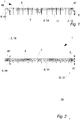
Fig. 2 illustrates liquid distributingsystem 1, as seen from the top. - In this embodiment of the invention the distributing
means 5 is completely self-controlling and can therefore function unmanned. However, in another embodiment the distributingmeans 5 could require an operator to control the operation of the distributingmeans 5 and the distributingmeans 5 could in such case be provided with a seat or an operator cabin. In another embodiment the distributingmeans 5 would be self-controlled when it crosses the field but it would require the control of an operator during start-up, shut-down and/or during negotiating turns and/or obstacles. -
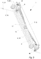
Fig. 3 illustrates a liquid distributing system, as seen from in perspective from the bottom. - The tap means 7 will be discussed more in relation with
figs. 18-22 but infig. 3 the tap means 7 is shown comprising a tap housing 10 stretching almost the entire width of the distributingmeans 5. - In this embodiment of the invention the tap housing 10 is formed by a flexible tarpaulin material to allow the distributing
means 5 and the tap housing 10 to be folded during road transport and/or to reduce the risk of hardened material build-up on the surfaces of the housing 10. However, in another embodiment the tap housing 10 could be formed in a more rigid material such as steel, plastic or fibre reinforced plastic. - In this embodiment of the invention the tap housing 10 is formed with a bottom surface sloping downwards towards a centrally arranged exit hole hereby forming a
liquid guide 17 for leading the tapped liquid to the delivery means 8. - In this embodiment the delivery means 8 of the distributing
means 5 comprises a central distributingpump 13 for pumping the liquid out through all the drag hoses 14. However, in another embodiment the tap means 7 or the delivery means 8 could comprise individual chambers which could be filled as the valves 11 of theliquid conduit 2 pass, where after the liquid could be delivered to the field by means of individual distributing pumps or simply by means of gravitational pull. - In a preferred embodiment of the invention the tap means 7 comprises one or two
flow blocking devices 16 as disclosed infigs. 18-21 and valve control means as disclosed infigs. 18-22 . -
Fig. 4 illustrates a liquid distributingsystem 1 distributing slurry on afield 3, as seen from the top, wherein the hatched area illustrates the areas of thefield 13 on which the distributingmeans 5 has distributed liquid so far. - In this embodiment stationary pressurizing means 4 are placed at the edge of the
field 3 and asupply hose 41 is rolled out in the headland of thefield 3 to connect the pressurizing means 4 with a mobileliquid conduit trolley 15 which in turn supplies liquid to the distributingmeans 5 by means of theliquid conduit 2. - However, in another embodiment of the invention the pressurizing means 4 could be mobile and e.g. be connected directly to the
liquid conduit 2, hereby avoiding the use of aliquid conduit trolley 15. - The distributing means 5 is traveling across the
field 3 in the longitudinal direction of theliquid conduit 2 and since the distributingmeans 5 comprises conduit displacing means 9 theliquid conduit 2 is displaced in a direction transverse to the longitudinal direction in accordance with the motion of the distributingmeans 5 in the longitudinal direction. Thus, as the distributingmeans 5 taps liquid from theliquid conduit 2 it also displaces theliquid conduit 2 transversely so that it is in position to be picked up by the distributingmeans 5 and tapped when the distributingmeans 5 does the next run across the field displaced but parallel to the previous run. - In another embodiment of the invention the
liquid conduit 2 could be pressurised from both sides i.e. from both ends of theconduits 2, 19 e.g. to compensate for pressure drop if thefield 3 was very long or to double the capacity. In such a case the pressurizing means 4 would be provided at both ends of the field and both headlands could comprise aliquid conduit trolley 15. -
Fig. 5 illustrates aliquid conduit trolley 15, as seen from the top. - The
liquid conduit trolley 15 can e.g. help the distributingmeans 5 in negotiating turns and it can in this embodiment reel up thesupply hose 41 on a supply hose coil 43 - as the distributingmeans 5 moves transversely (down towards the pressurizing means 4) - and buffering the liquid conduit 2 - as shown infigs. 6-9 - e.g. to compensate for any irregular (non-orthogonal) shape of thefield 3 using theliquid conduit coil 44. - To reduce the weight of the
liquid conduit trolley 15, aslittle supply hose 41 andliquid conduit 2 are in use as possible, in that the liquid-filledexcess hose 41 andconduit 2 will have to be rolled up on thededicated coils unused hose 41 andconduit 2 is in this embodiment therefore rolled up on separatespare coils 45 to be used if the necessary. - The following
figures 6-9 illustrates a liquid distributingsystem 1 wherein the distributingmeans 5 are negotiating a turn by the help of theliquid conduit trolley 15. - In the present embodiment the distributing
means 5 and theliquid conduit trolley 15 are self-controlled and the turning process is made without the aid of a human operator e.g. on the basis of input from sensors, cameras, GPS units or other. However in another embodiment the liquid distributingsystem 1 could require permanent human control or an operator could be summoned as the distributing means 5 approaches a turn (or at least the turn at the end of thefield 3 where the pressurizing means 4 and/or theliquid conduit trolley 15 is located) to control the turning process manually or semi-automatically. -
Fig. 6 illustrates a liquid distributingsystem 1 that have just reached one end of thefield 3, as seen from the top. -
Fig. 7 illustrates a liquid distributingsystem 1 at the start of a turning procedure, as seen from the top. - The turning process can obviously be performed in many ways, but in this embodiment of the invention the end of the distributing means 5 closest to the
liquid conduit trolley 15 will stay at a substantially constant distance from theliquid conduit trolley 15 as theliquid conduit trolley 15 travels along the edge of thefield 3 while the other end of the distributingmeans 5 moves away from the edge of thefield 3 to allow the other end and theliquid conduit trolley 15 to pass it. -
Fig. 8 illustrates a liquid distributingsystem 1 around the middle of a turning procedure, as seen from the top. - As soon as the
liquid conduit trolley 15 has passed the distributingmeans 5, the distributing means 5 starts moving towards the edge of thefield 3 again. -
Fig. 9 illustrates a liquid distributingsystem 1 after a turning procedure, as seen from the top. - When the edge of the
field 3 has been reached, the distributingmeans 5 can start a new run across thefield 3. -
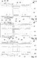
Fig. 10 illustrates a valve 11, as seen in perspective. - In this embodiment the valve 11 comprises a
cylindrical valve housing 23 with a slidable tap-aperture cover 20 arranged on the outside of thevalve housing 23. However in another embodiment the tap-aperture cover 20 could be arranged on the inside of thevalve housing 23. - In this embodiment of the invention the
valve housing 23 and most of the parts of the valve 11 is made from metal such as aluminium, an aluminium alloy, steel, stainless steel or another metal. However, in another embodiment of the invention thevalve housing 23 and most of the other valve parts may be made from hard rigid plastic or another natural or synthetic material. -
Fig. 11 illustrates a valve 11, as seen from the end. - In this embodiment of the invention the tap-
aperture cover 20 is covering the tap-apertures 21 and the position fixation means 25 are therefore disengaged and forced at least partly into the cavity inside the valve 11. -
Fig. 12 illustrates a cross section through the middle of a valve 11 in a closed state, as seen from the side. - In this embodiment of the invention the valve 11 comprises a number of tap-
apertures 21 distributed evenly around the centre of thevalve housing 23. The fluid flowing through the inside of the valve 11 can hereby be tapped through the tap-apertures 21 when the valve 11 is in an open state. - The tap-
apertures 21 are covered by a tap-aperture cover 20 in the form of a ring that can slide along the outside surface of thevalve housing 23. In this embodiment of the invention the tap-aperture cover 20 can selectively slide in both axial directions of the valve 11, so that the valve 11 can be changed from the present closed state to an open state no matter which axial direction the tap-aperture cover 20 is pushed in. To ensure that the valve 11 remains in a closed state when not affected by external forces, the valve 11 is also provided with spring means 22 arranged on either sides of the tap-aperture cover 20. - However, in another embodiment of the invention the tap-
aperture cover 20 would only be able to be pushed in one axial direction and the valve 11 would therefore only comprise one spring means 22. - In the present illustration the tap-
aperture cover 20 has just been pushed as indicated by the arrow to start an opening process of the valve 11. -
Fig. 13 illustrates a cross section through the middle of a valve 11 approaching an open state, as seen from the side. The tap apertures 21 are at this time half uncovered and pressurised liquid or gas will start to be pressed out of thetap apertures 21. -
Fig. 14 illustrates a cross section through the middle of a valve 11 locked in an open state, as seen from the side. - In this embodiment of the invention the valve 11 also comprises locking means 24 ensuring than when the tap-
aperture cover 20 is pushed almost to an open state of the valve 11 as shown infig. 14 the lock spring means 27 will push position fixation means 25 out through position fixation meansapertures 26 in thevalve housing 23 to prevent the compressed spring means 22 from pushing the tap-aperture cover 20 back to a closed state of the valve 11. Hereby the valve 11 is provided with a self-retaining function ensuring that the valve 11 remains in the open state until the locking means 24 are actively released. -
Fig. 15 illustrates a cross section through the middle of a valve 11 in an open state while the locking means 24 is being released, as seen from the side andfig. 16 illustrates a cross section through the middle of a valve 11 in an open state after the locking means 24 has been released, as seen from the side. - In this embodiment of the invention a
release ring 42 of the locking means 11 is temporarily pushed backwards as indicated by the arrow whereby an upper part of the locking means is pushed forward by a spring arranged on the outside of the tap-aperture cover 20 so that this upper part pushes the position fixation means 25 a bit down through the position fixation meansapertures 26 and so that the tap-aperture cover 20 may move towards the tap-apertures 21 and at the same time press the position fixation means 25 the rest of the way down. -
Fig. 17 illustrates a cross section through the middle of a valve 11 approaching a closed state, as seen from the side. As disclosed the tap-aperture cover 20 is now retaining the position fixation means 25 in the position fixation meansapertures 26 so that the spring means 22 may push the tap-aperture cover 20 all the way to the middle position of the valve 11 to close the tap-apertures 21. - The tap-
aperture cover 20 will now again remain in a closed state until it is mechanically pushed to either sides. -
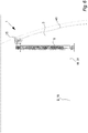
Fig. 18 illustrates a fluid distribution system 30 comprising a flexible hose 18 with a valve 11 approaching aflow blocking device 16, as seen from the side. - The flexible hose 18 of the fluid distribution system 30 illustrated in
figs. 18-22 could in a preferred embodiment of the invention be the same as the previously describedliquid conduit 2 or fluid conduit 19 and theflow blocking device 16 and the valve control means 12 illustrated infigs. 18-22 could in a preferred embodiment of the invention be arranged on the previously described distributingmeans 5 e.g. inside the tap housing 10. - If the fluid or
liquid conduit 2, 19 was pressurised from both ends with different fluids e.g. if slurry was provided from one end of the fluid orliquid conduit 2, 19 and water was provided from the other end of the fluid orliquid conduit 2, 19, the slurry could e.g. be sprayed out on relatively large crops where after water could be sprayed on the same crops to wash the slurry down to the soil - e.g. to relieve smell problems and enhance sorption of nutrients - all in one go and continuously as the distributingmeans 5 moves across thefield 3. In such a case aflow blocking device 16 could also be provided at the middle of the tap housing 10 to separate the two fluids in the fluid orliquid conduit 2, 19 to form a dual tap housing 10. - In another embodiment this double fluid technique could be used to irrigate and distribute pesticides or other at the same time or if the fluid distribution system 30 was used in a different configuration (i.e. other than for agricultural use) the two different fluids could be any combination of known fluids such as soap-water, paint, liquid food products, CO2 or other.
- In this embodiment of the invention both ends of the valve 11 is provided with hose connection means 28 for connecting a
hose part 29 to either ends of the valve 11. However, in another embodiment of the invention the hose 18 could be throughgoing. -
Fig. 19 illustrates a valve 11 passing afirst flow blocker 32, as seen from the side. - As the valve 11 passes the
first flow blocker 32, thesecond flow blocker 33 will remain in a compressing state so that the pressurised content in thehose 2, 18, 19 will in principle never pass thesecond flow blocker 33 if not desired. - In this embodiment of the invention both the
first flow blocker 32 and thesecond flow blocker 33 are formed as two wheels 35 compressing theconduit 2, 19 from opposite sides. In this case theouter diameter 36 of the wheels 35 is bigger than theouter diameter 37 of theconduit 2, 19 to ensure that the wheels 35 inherently will be guided out and over a rigid incompressible portion of theconduits 2, 18, 19 such as a valve 11. In another embodiment theflow blockers hose 2, 18, 19 from only one side against a fixed fence and in such a case the wheels 35 would have anouter diameter 36 that is more than twice as big as theouter diameter 37 of theconduit 2, 18, 19. - In this embodiment of the invention the
first flow blocker 32 and thesecond flow blocker 33 each comprises guide means 39 (not shown) for guiding the radial movement (radial in relation to thehose 2, 18, 19) of theflow blockers flow blockers flow blockers flow blockers - In an embodiment of the invention the
first flow blocker 32 and/or thesecond flow blocker 33 would also comprise position displacement means 40 (not shown) e.g. in the form of an electrical linear actuator, a pneumatic cylinder or an hydraulic cylinder for selectively opening of closing theflow blockers first flow blocker 32 and/or thesecond flow blocker 33 could also be at least partly manually operated. -
Fig. 20 illustrates a valve 11 passing valve control means 12, as seen from the side. - As soon as the valve 11 has passed the
first flow blocker 32, the flexible hose 18 is compressed again by the wheels 35 and the valve continues through the valve control means 12 in which therelease ring 42 is engaged by the valve control means 12 so that the valve 11 changes from an open state to an closed state. - To ensure that the
conduit 2, 18, 19 is emptied as efficiently as possible theflow blocking device 16 and the valve control means 12 is tilted in an upwards angle as shown infigs 18-21 to allow the valve 11 to drain after the pressure has been relieved - when it has passed the first flow blocker 32 - and until the valve is closed by the valve control means 12. -
Fig. 21 illustrates a valve 11 passing asecond flow blocker 33, as seen from the side. - The valve 11 will now pass through the
second flow blocker 33 while thefirst flow blocker 32 remain engaged and as soon as the valve 11 has passed thesecond flow blocker 33 thesecond flow blocker 33 will again compress thehose 2, 18, 19. -
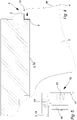
Fig. 22 illustrates cross section of a valve 11 engaging valve control means 12, as seen from the side. - The valve 11 and particularly the valve control means 12 can obviously be designed in many ways but since the valve 11 is cylindrical it is also advantageous to form the valve control means 12 with a cylindrical housing through which the valve 11 can pass while being switched. In this embodiment the valve control means 12 comprises a number of levers and arm that temporarily engages the desired parts of the valve 11 as it passes through the valve control means 12.
- In an embodiment of the invention the distributing means 5 - or another device tapping fluid from the
conduits 2, 29 - would most likely comprise two valve control means 12 e.g. arranged at either ends of the tap housing 10 so that the valve 11 can be opened by the valve control means 12 as soon as it enters the tap housing 10 and the closed again before it leaves the tap housing 10. - If the fluid or
liquid conduit 2, 19 always passes the same way through the tap housing 10 theflow blocking device 16 would only have to be arranged around the valve control means 12 at the end where the valve 11 leaves the tap housing 10, but in most cases it would be preferable if theconduits 2, 19 could travel in both axial directions through the tap housing 10 and then aflow blocking device 16 would have to be arranged at both valve control means 12. Or in an embodiment two valve control means 12 could be arranged between thefirst flow blocker 32 and thesecond flow blocker 33 of the sameflow blocking device 16. - The invention has been exemplified above with reference to specific examples of liquid distributing
system 1, valves 11, valve control means 12,flow blocking devices 16 and other. However, it should be understood that the invention is not limited to the particular examples described above but may be designed and altered in a multitude of varieties within the scope of the invention as specified in the claims. -
- 1. Liquid distributing system
- 2. Liquid conduit
- 3. Field
- 4. Pressurising means
- 5. Distributing means
- 6. Drive means
- 7. Tap means
- 8. Delivery means
- 9. Conduit displacing means
- 10. Tap housing
- 11. Valve
- 12. Valve control means
- 13. Distributing pump
- 14. Drag hose
- 15. Liquid conduit trolley
- 16. Flow blocking device
- 17. Liquid guide
- 18. Flexible hose
- 19. Fluid conduit
- 20. Tap-aperture covers
- 21. Tap-apertures
- 22. Spring means
- 23. Valve housing
- 24. Locking means
- 25. Position fixation means
- 26. Position fixation means aperture
- 27. Lock spring means
- 28. Hose connection means
- 29. Hose parts
- 30. Fluid distribution system
- 31. Rigid incompressible portion
- 32. First flow blocker
- 33. Second flow blocker
- 34. Blocking means
- 35. Wheel
- 36. Outer diameter of wheel
- 37. Outer diameter of hose
- 38. Blocking spring means
- 39. Guide means
- 40. Position displacement means
- 41. Supply hose
- 42. Release ring
- 43. Supply hose coil
- 44. Liquid conduit coil
- 45. Spare coil
- 46. Conduit pickup means
- 47. Conduit replacing means
- 48. Guide wheel
Claims (14)
- A liquid distributing system (1) for distributing liquids such as water or slurry on a field (3), said system (1) comprising,
a liquid conduit (2) for being placed in a longitudinal direction on said field (3),
pressurising means (4) for pressurising a liquid in said liquid conduit (2),
distributing means (5) comprising drive means (6) for moving said distributing means (5) in said longitudinal direction, wherein said distributing means (5) comprises tap means (7) for tapping liquid from said liquid conduit (2) and delivery means (8) for distributing said liquid to said field (3),
said distributing means (5) further comprises conduit displacing means (9) for displacing said liquid conduit (2) in a direction transverse to said longitudinal direction on said field (3).
characterised in that
said liquid conduit (2) comprises valves (11) and wherein said tap means (7) comprises valve control means (12) for controlling said valves (11). - A liquid distributing system (1) according to claim 1, wherein said conduit displacing means (9) comprises means for displacing said liquid conduit (2) in accordance with said motion of said distributing means (5) in said longitudinal direction.
- A liquid distributing system (1) according to claim 1 or 2, wherein said tap means (7) comprises a tap housing (10) substantially surrounding said tap means (7), wherein said tap housing (10) comprises a liquid guide (17) for leading said liquid to said delivery means (8).
- A liquid distributing system (1) according to any of the preceding claims, wherein said delivery means (8) comprises a distributing pump (13) mounted on said distributing means (5).
- A liquid distributing system (1) according to any of the preceding claims, wherein said delivery means (8) comprises a plurality of drag hoses (14) for delivering said liquid at or on the soil.
- A liquid distributing system (1) according to any of the preceding claims, wherein said liquid distributing system (1) further comprises a liquid conduit trolley (15) for managing said liquid conduit (2) and wherein said liquid conduit trolley (15) is coupled to one end of said liquid conduit (2).
- A liquid distributing system (1) according to any of the preceding claims, wherein said tap means (7) comprises a flow blocking device (16) for substantially emptying said liquid conduit (2) as it passes said tap means (7).
- A liquid distributing system (1) according to any of the preceding claims, wherein said conduit displacing means (9) comprises conduit pickup means (46) including means for picking said liquid conduit (2) up of said field (3) and leading it to said tap means (7).
- A liquid distributing system (1) according to any of the preceding claims, wherein said conduit displacing means (9) comprises conduit replacing means (47) including means for leading said liquid conduit (2) from said tap means (7) and back down onto said field (3).
- A liquid distributing system (1) according to claims 8 and 9, wherein said conduit pickup means (46) is arranged separate from said conduit replacing means (47).
- A liquid distributing system (1) according to claims 8 and 9, wherein said conduit pickup means (46) and said conduit replacing means (47) are arranged on opposite sides of said tap means (7).
- A method for distributing liquid on a field (3) by means of a liquid distributing system (1) according to any of the preceding claims, said method comprising the steps of:• placing a liquid conduit (2) comprising valves (11) on said field (3),• pressurising a liquid in said liquid conduit (2),• moving distributing means (5) along said liquid conduit (2) while at least periodically tapping said liquid from said liquid conduit (2) by controlling said valves (11) by means of valve control means (12) of said distributing means (5) and distributing it to said field (3),• displacing said liquid conduit (2) on said field (3) in a direction transverse to said liquid conduit (2) by means of conduit displacing means (9) of said distributing means (5).
- A method according to claim 12, wherein said liquid conduit (2) is picked up from said field (3), tapped and replaced on said field (3) in a continuous sequential process.
- Use of a liquid distributing system (1) according to any of claims 1-11 for distributing slurry to a field (3).
Priority Applications (1)
| Application Number | Priority Date | Filing Date | Title |
|---|---|---|---|
| PL13728951T PL2858479T3 (en) | 2012-06-11 | 2013-06-11 | A liquid distributing system and a method for distributing liquid on a field |
Applications Claiming Priority (2)
| Application Number | Priority Date | Filing Date | Title |
|---|---|---|---|
| DKPA201270315 | 2012-06-11 | ||
| PCT/DK2013/050188 WO2013185774A2 (en) | 2012-06-11 | 2013-06-11 | A liquid distributing system and a method for distributing liquid on a field |
Publications (2)
| Publication Number | Publication Date |
|---|---|
| EP2858479A2 EP2858479A2 (en) | 2015-04-15 |
| EP2858479B1 true EP2858479B1 (en) | 2020-04-08 |
Family
ID=48626235
Family Applications (1)
| Application Number | Title | Priority Date | Filing Date |
|---|---|---|---|
| EP13728951.8A Active EP2858479B1 (en) | 2012-06-11 | 2013-06-11 | A liquid distributing system and a method for distributing liquid on a field |
Country Status (4)
| Country | Link |
|---|---|
| EP (1) | EP2858479B1 (en) |
| DK (1) | DK2858479T3 (en) |
| PL (1) | PL2858479T3 (en) |
| WO (1) | WO2013185774A2 (en) |
Cited By (1)
| Publication number | Priority date | Publication date | Assignee | Title |
|---|---|---|---|---|
| WO2025053751A1 (en) * | 2023-09-07 | 2025-03-13 | Agxeed Holding B.V. | A drag hose system for distributing a fluid composition from a supply over a piece of farmland |
Family Cites Families (6)
| Publication number | Priority date | Publication date | Assignee | Title |
|---|---|---|---|---|
| US2931579A (en) * | 1957-12-27 | 1960-04-05 | Clarence W Ruddell | Automatic irrigation system |
| US4877189A (en) * | 1987-05-18 | 1989-10-31 | Williams Christopher G | Irrigation system |
| DE10311957A1 (en) * | 2003-03-18 | 2004-09-30 | Wolfgang Strehle Service Gmbh | Method for delivery of fluids to a specified ground area involves use of equipment comprising a hose drum carrier unit and a fluid distributer unit which are towed separately |
| US7140563B2 (en) * | 2004-07-16 | 2006-11-28 | Nelson Irrigation Corporation | Linear-feed irrigation apparatus and related method |
| NL2000121C2 (en) * | 2006-07-03 | 2008-01-07 | Veenhuis Machines | Device and method for fertilizing soil. |
| US8256692B2 (en) * | 2009-10-21 | 2012-09-04 | Bazooka Farmstar, Inc. | Positioning apparatus for sludge distributing hose |
-
2013
- 2013-06-11 WO PCT/DK2013/050188 patent/WO2013185774A2/en not_active Ceased
- 2013-06-11 DK DK13728951.8T patent/DK2858479T3/en active
- 2013-06-11 EP EP13728951.8A patent/EP2858479B1/en active Active
- 2013-06-11 PL PL13728951T patent/PL2858479T3/en unknown
Non-Patent Citations (1)
| Title |
|---|
| None * |
Cited By (1)
| Publication number | Priority date | Publication date | Assignee | Title |
|---|---|---|---|---|
| WO2025053751A1 (en) * | 2023-09-07 | 2025-03-13 | Agxeed Holding B.V. | A drag hose system for distributing a fluid composition from a supply over a piece of farmland |
Also Published As
| Publication number | Publication date |
|---|---|
| WO2013185774A3 (en) | 2014-04-10 |
| PL2858479T3 (en) | 2020-08-24 |
| WO2013185774A2 (en) | 2013-12-19 |
| DK2858479T3 (en) | 2020-07-13 |
| EP2858479A2 (en) | 2015-04-15 |
Similar Documents
| Publication | Publication Date | Title |
|---|---|---|
| US7744012B2 (en) | Liquid manure spreading apparatus | |
| US7472659B2 (en) | Planting apparatus and method | |
| US3942722A (en) | Ground treatment apparatus | |
| AU2008301161A1 (en) | Sectional meter shut-off and agricultural implement having sectional meter shut-off | |
| US11083131B2 (en) | Method and apparatus for applying liquid nutrients between parallel rows of standing crops | |
| US10189673B2 (en) | Method and apparatus for applying liquid nutrients between parallel rows of standing crops | |
| US3235009A (en) | Traveling irrigation sprinkler and method of irrigation sprinkling | |
| US3739985A (en) | Irrigation equipment for tractor | |
| DE102017128675A1 (en) | irrigation system | |
| US10219429B2 (en) | Method and apparatus for applying liquid nutrients between parallel rows of standing crops | |
| US20150196001A1 (en) | Irrigation Systems | |
| US3608827A (en) | Linearly movable irrigation system | |
| WO2013185774A2 (en) | A liquid distributing system and a method for distributing liquid on a field | |
| CA2995611A1 (en) | Hose reel | |
| US10631461B1 (en) | Device and system for extracting and densifying agricultural plastics | |
| KR200490489Y1 (en) | Greenhouse Automatic Sprinkler Device | |
| KR102259602B1 (en) | Automatic agricultural chemical spraying apparatus | |
| KR101920690B1 (en) | Devices for supplying fluids to crops | |
| US20230263089A1 (en) | Systems, methods and apparatuses for liquid manure spreading | |
| WO2008004864A1 (en) | Device and method for manuring land | |
| BE1006380A3 (en) | Trap air lines automatic machines spreading manure or injection or other fertilizer. | |
| US20230114783A1 (en) | Applicator | |
| WO2025053751A1 (en) | A drag hose system for distributing a fluid composition from a supply over a piece of farmland | |
| KR200214246Y1 (en) | A cropdusting system | |
| CA3012528C (en) | Method and apparatus for applying liquid nutrients between parallel rows of standing crops |
Legal Events
| Date | Code | Title | Description |
|---|---|---|---|
| PUAI | Public reference made under article 153(3) epc to a published international application that has entered the european phase |
Free format text: ORIGINAL CODE: 0009012 |
|
| 17P | Request for examination filed |
Effective date: 20150108 |
|
| AK | Designated contracting states |
Kind code of ref document: A2 Designated state(s): AL AT BE BG CH CY CZ DE DK EE ES FI FR GB GR HR HU IE IS IT LI LT LU LV MC MK MT NL NO PL PT RO RS SE SI SK SM TR |
|
| AX | Request for extension of the european patent |
Extension state: BA ME |
|
| DAX | Request for extension of the european patent (deleted) | ||
| STAA | Information on the status of an ep patent application or granted ep patent |
Free format text: STATUS: EXAMINATION IS IN PROGRESS |
|
| 17Q | First examination report despatched |
Effective date: 20181119 |
|
| GRAP | Despatch of communication of intention to grant a patent |
Free format text: ORIGINAL CODE: EPIDOSNIGR1 |
|
| STAA | Information on the status of an ep patent application or granted ep patent |
Free format text: STATUS: GRANT OF PATENT IS INTENDED |
|
| INTG | Intention to grant announced |
Effective date: 20191104 |
|
| GRAS | Grant fee paid |
Free format text: ORIGINAL CODE: EPIDOSNIGR3 |
|
| GRAA | (expected) grant |
Free format text: ORIGINAL CODE: 0009210 |
|
| STAA | Information on the status of an ep patent application or granted ep patent |
Free format text: STATUS: THE PATENT HAS BEEN GRANTED |
|
| AK | Designated contracting states |
Kind code of ref document: B1 Designated state(s): AL AT BE BG CH CY CZ DE DK EE ES FI FR GB GR HR HU IE IS IT LI LT LU LV MC MK MT NL NO PL PT RO RS SE SI SK SM TR |
|
| RIN1 | Information on inventor provided before grant (corrected) |
Inventor name: ANDERSEN, LARS SKOVLUND |
|
| REG | Reference to a national code |
Ref country code: CH Ref legal event code: EP Ref country code: AT Ref legal event code: REF Ref document number: 1253117 Country of ref document: AT Kind code of ref document: T Effective date: 20200415 |
|
| REG | Reference to a national code |
Ref country code: DE Ref legal event code: R096 Ref document number: 602013067670 Country of ref document: DE |
|
| REG | Reference to a national code |
Ref country code: IE Ref legal event code: FG4D |
|
| REG | Reference to a national code |
Ref country code: DK Ref legal event code: T3 Effective date: 20200707 |
|
| REG | Reference to a national code |
Ref country code: SE Ref legal event code: TRGR |
|
| REG | Reference to a national code |
Ref country code: NL Ref legal event code: FP |
|
| REG | Reference to a national code |
Ref country code: LT Ref legal event code: MG4D |
|
| PG25 | Lapsed in a contracting state [announced via postgrant information from national office to epo] |
Ref country code: LT Free format text: LAPSE BECAUSE OF FAILURE TO SUBMIT A TRANSLATION OF THE DESCRIPTION OR TO PAY THE FEE WITHIN THE PRESCRIBED TIME-LIMIT Effective date: 20200408 Ref country code: PT Free format text: LAPSE BECAUSE OF FAILURE TO SUBMIT A TRANSLATION OF THE DESCRIPTION OR TO PAY THE FEE WITHIN THE PRESCRIBED TIME-LIMIT Effective date: 20200817 Ref country code: FI Free format text: LAPSE BECAUSE OF FAILURE TO SUBMIT A TRANSLATION OF THE DESCRIPTION OR TO PAY THE FEE WITHIN THE PRESCRIBED TIME-LIMIT Effective date: 20200408 Ref country code: GR Free format text: LAPSE BECAUSE OF FAILURE TO SUBMIT A TRANSLATION OF THE DESCRIPTION OR TO PAY THE FEE WITHIN THE PRESCRIBED TIME-LIMIT Effective date: 20200709 Ref country code: IS Free format text: LAPSE BECAUSE OF FAILURE TO SUBMIT A TRANSLATION OF THE DESCRIPTION OR TO PAY THE FEE WITHIN THE PRESCRIBED TIME-LIMIT Effective date: 20200808 Ref country code: NO Free format text: LAPSE BECAUSE OF FAILURE TO SUBMIT A TRANSLATION OF THE DESCRIPTION OR TO PAY THE FEE WITHIN THE PRESCRIBED TIME-LIMIT Effective date: 20200708 |
|
| REG | Reference to a national code |
Ref country code: AT Ref legal event code: MK05 Ref document number: 1253117 Country of ref document: AT Kind code of ref document: T Effective date: 20200408 |
|
| PG25 | Lapsed in a contracting state [announced via postgrant information from national office to epo] |
Ref country code: RS Free format text: LAPSE BECAUSE OF FAILURE TO SUBMIT A TRANSLATION OF THE DESCRIPTION OR TO PAY THE FEE WITHIN THE PRESCRIBED TIME-LIMIT Effective date: 20200408 Ref country code: HR Free format text: LAPSE BECAUSE OF FAILURE TO SUBMIT A TRANSLATION OF THE DESCRIPTION OR TO PAY THE FEE WITHIN THE PRESCRIBED TIME-LIMIT Effective date: 20200408 Ref country code: BG Free format text: LAPSE BECAUSE OF FAILURE TO SUBMIT A TRANSLATION OF THE DESCRIPTION OR TO PAY THE FEE WITHIN THE PRESCRIBED TIME-LIMIT Effective date: 20200708 Ref country code: LV Free format text: LAPSE BECAUSE OF FAILURE TO SUBMIT A TRANSLATION OF THE DESCRIPTION OR TO PAY THE FEE WITHIN THE PRESCRIBED TIME-LIMIT Effective date: 20200408 |
|
| PG25 | Lapsed in a contracting state [announced via postgrant information from national office to epo] |
Ref country code: AL Free format text: LAPSE BECAUSE OF FAILURE TO SUBMIT A TRANSLATION OF THE DESCRIPTION OR TO PAY THE FEE WITHIN THE PRESCRIBED TIME-LIMIT Effective date: 20200408 |
|
| REG | Reference to a national code |
Ref country code: DE Ref legal event code: R097 Ref document number: 602013067670 Country of ref document: DE |
|
| PG25 | Lapsed in a contracting state [announced via postgrant information from national office to epo] |
Ref country code: IT Free format text: LAPSE BECAUSE OF FAILURE TO SUBMIT A TRANSLATION OF THE DESCRIPTION OR TO PAY THE FEE WITHIN THE PRESCRIBED TIME-LIMIT Effective date: 20200408 Ref country code: ES Free format text: LAPSE BECAUSE OF FAILURE TO SUBMIT A TRANSLATION OF THE DESCRIPTION OR TO PAY THE FEE WITHIN THE PRESCRIBED TIME-LIMIT Effective date: 20200408 Ref country code: RO Free format text: LAPSE BECAUSE OF FAILURE TO SUBMIT A TRANSLATION OF THE DESCRIPTION OR TO PAY THE FEE WITHIN THE PRESCRIBED TIME-LIMIT Effective date: 20200408 Ref country code: CZ Free format text: LAPSE BECAUSE OF FAILURE TO SUBMIT A TRANSLATION OF THE DESCRIPTION OR TO PAY THE FEE WITHIN THE PRESCRIBED TIME-LIMIT Effective date: 20200408 Ref country code: AT Free format text: LAPSE BECAUSE OF FAILURE TO SUBMIT A TRANSLATION OF THE DESCRIPTION OR TO PAY THE FEE WITHIN THE PRESCRIBED TIME-LIMIT Effective date: 20200408 Ref country code: EE Free format text: LAPSE BECAUSE OF FAILURE TO SUBMIT A TRANSLATION OF THE DESCRIPTION OR TO PAY THE FEE WITHIN THE PRESCRIBED TIME-LIMIT Effective date: 20200408 Ref country code: SM Free format text: LAPSE BECAUSE OF FAILURE TO SUBMIT A TRANSLATION OF THE DESCRIPTION OR TO PAY THE FEE WITHIN THE PRESCRIBED TIME-LIMIT Effective date: 20200408 Ref country code: MC Free format text: LAPSE BECAUSE OF FAILURE TO SUBMIT A TRANSLATION OF THE DESCRIPTION OR TO PAY THE FEE WITHIN THE PRESCRIBED TIME-LIMIT Effective date: 20200408 |
|
| REG | Reference to a national code |
Ref country code: CH Ref legal event code: PL |
|
| PLBE | No opposition filed within time limit |
Free format text: ORIGINAL CODE: 0009261 |
|
| STAA | Information on the status of an ep patent application or granted ep patent |
Free format text: STATUS: NO OPPOSITION FILED WITHIN TIME LIMIT |
|
| PG25 | Lapsed in a contracting state [announced via postgrant information from national office to epo] |
Ref country code: SK Free format text: LAPSE BECAUSE OF FAILURE TO SUBMIT A TRANSLATION OF THE DESCRIPTION OR TO PAY THE FEE WITHIN THE PRESCRIBED TIME-LIMIT Effective date: 20200408 |
|
| 26N | No opposition filed |
Effective date: 20210112 |
|
| PG25 | Lapsed in a contracting state [announced via postgrant information from national office to epo] |
Ref country code: LU Free format text: LAPSE BECAUSE OF NON-PAYMENT OF DUE FEES Effective date: 20200611 |
|
| REG | Reference to a national code |
Ref country code: BE Ref legal event code: MM Effective date: 20200630 |
|
| PG25 | Lapsed in a contracting state [announced via postgrant information from national office to epo] |
Ref country code: LI Free format text: LAPSE BECAUSE OF NON-PAYMENT OF DUE FEES Effective date: 20200630 Ref country code: CH Free format text: LAPSE BECAUSE OF NON-PAYMENT OF DUE FEES Effective date: 20200630 |
|
| PG25 | Lapsed in a contracting state [announced via postgrant information from national office to epo] |
Ref country code: BE Free format text: LAPSE BECAUSE OF NON-PAYMENT OF DUE FEES Effective date: 20200630 Ref country code: SI Free format text: LAPSE BECAUSE OF FAILURE TO SUBMIT A TRANSLATION OF THE DESCRIPTION OR TO PAY THE FEE WITHIN THE PRESCRIBED TIME-LIMIT Effective date: 20200408 |
|
| PG25 | Lapsed in a contracting state [announced via postgrant information from national office to epo] |
Ref country code: TR Free format text: LAPSE BECAUSE OF FAILURE TO SUBMIT A TRANSLATION OF THE DESCRIPTION OR TO PAY THE FEE WITHIN THE PRESCRIBED TIME-LIMIT Effective date: 20200408 Ref country code: MT Free format text: LAPSE BECAUSE OF FAILURE TO SUBMIT A TRANSLATION OF THE DESCRIPTION OR TO PAY THE FEE WITHIN THE PRESCRIBED TIME-LIMIT Effective date: 20200408 Ref country code: CY Free format text: LAPSE BECAUSE OF FAILURE TO SUBMIT A TRANSLATION OF THE DESCRIPTION OR TO PAY THE FEE WITHIN THE PRESCRIBED TIME-LIMIT Effective date: 20200408 |
|
| PG25 | Lapsed in a contracting state [announced via postgrant information from national office to epo] |
Ref country code: MK Free format text: LAPSE BECAUSE OF FAILURE TO SUBMIT A TRANSLATION OF THE DESCRIPTION OR TO PAY THE FEE WITHIN THE PRESCRIBED TIME-LIMIT Effective date: 20200408 |
|
| PGFP | Annual fee paid to national office [announced via postgrant information from national office to epo] |
Ref country code: PL Payment date: 20250606 Year of fee payment: 13 Ref country code: DE Payment date: 20250626 Year of fee payment: 13 |
|
| PGFP | Annual fee paid to national office [announced via postgrant information from national office to epo] |
Ref country code: GB Payment date: 20250617 Year of fee payment: 13 Ref country code: DK Payment date: 20250619 Year of fee payment: 13 |
|
| PGFP | Annual fee paid to national office [announced via postgrant information from national office to epo] |
Ref country code: NL Payment date: 20250624 Year of fee payment: 13 |
|
| PGFP | Annual fee paid to national office [announced via postgrant information from national office to epo] |
Ref country code: FR Payment date: 20250624 Year of fee payment: 13 |
|
| PGFP | Annual fee paid to national office [announced via postgrant information from national office to epo] |
Ref country code: IE Payment date: 20250617 Year of fee payment: 13 |
|
| PGFP | Annual fee paid to national office [announced via postgrant information from national office to epo] |
Ref country code: SE Payment date: 20250619 Year of fee payment: 13 |