EP2858294B1 - Feedback overhead reduction during crosstalk precoder initialization in DSL systems - Google Patents
Feedback overhead reduction during crosstalk precoder initialization in DSL systems Download PDFInfo
- Publication number
- EP2858294B1 EP2858294B1 EP14200354.0A EP14200354A EP2858294B1 EP 2858294 B1 EP2858294 B1 EP 2858294B1 EP 14200354 A EP14200354 A EP 14200354A EP 2858294 B1 EP2858294 B1 EP 2858294B1
- Authority
- EP
- European Patent Office
- Prior art keywords
- error
- bits
- error feedback
- feedback
- precoder
- Prior art date
- Legal status (The legal status is an assumption and is not a legal conclusion. Google has not performed a legal analysis and makes no representation as to the accuracy of the status listed.)
- Active
Links
- 230000009467 reduction Effects 0.000 title description 3
- 238000013139 quantization Methods 0.000 claims description 67
- 238000000034 method Methods 0.000 claims description 25
- 238000012549 training Methods 0.000 description 61
- 239000013598 vector Substances 0.000 description 20
- 230000007423 decrease Effects 0.000 description 17
- 230000006872 improvement Effects 0.000 description 15
- 239000011159 matrix material Substances 0.000 description 7
- 230000008569 process Effects 0.000 description 6
- 238000010586 diagram Methods 0.000 description 5
- 239000000969 carrier Substances 0.000 description 3
- 238000004891 communication Methods 0.000 description 3
- 238000005516 engineering process Methods 0.000 description 3
- 238000007726 management method Methods 0.000 description 3
- 230000011664 signaling Effects 0.000 description 3
- 101100129500 Caenorhabditis elegans max-2 gene Proteins 0.000 description 2
- 239000011230 binding agent Substances 0.000 description 2
- 101150012579 ADSL gene Proteins 0.000 description 1
- 102100020775 Adenylosuccinate lyase Human genes 0.000 description 1
- 108700040193 Adenylosuccinate lyases Proteins 0.000 description 1
- RYGMFSIKBFXOCR-UHFFFAOYSA-N Copper Chemical compound [Cu] RYGMFSIKBFXOCR-UHFFFAOYSA-N 0.000 description 1
- 240000004759 Inga spectabilis Species 0.000 description 1
- 230000003044 adaptive effect Effects 0.000 description 1
- 229910052802 copper Inorganic materials 0.000 description 1
- 239000010949 copper Substances 0.000 description 1
- 238000012937 correction Methods 0.000 description 1
- 238000013500 data storage Methods 0.000 description 1
- 230000001419 dependent effect Effects 0.000 description 1
- 230000006870 function Effects 0.000 description 1
- 238000012986 modification Methods 0.000 description 1
- 230000004048 modification Effects 0.000 description 1
- 238000012545 processing Methods 0.000 description 1
- 238000005070 sampling Methods 0.000 description 1
- 238000004088 simulation Methods 0.000 description 1
- 230000003595 spectral effect Effects 0.000 description 1
Images


Classifications
-
- H—ELECTRICITY
- H04—ELECTRIC COMMUNICATION TECHNIQUE
- H04B—TRANSMISSION
- H04B3/00—Line transmission systems
- H04B3/02—Details
- H04B3/32—Reducing cross-talk, e.g. by compensating
-
- H—ELECTRICITY
- H04—ELECTRIC COMMUNICATION TECHNIQUE
- H04B—TRANSMISSION
- H04B17/00—Monitoring; Testing
- H04B17/20—Monitoring; Testing of receivers
- H04B17/24—Monitoring; Testing of receivers with feedback of measurements to the transmitter
-
- H—ELECTRICITY
- H04—ELECTRIC COMMUNICATION TECHNIQUE
- H04L—TRANSMISSION OF DIGITAL INFORMATION, e.g. TELEGRAPHIC COMMUNICATION
- H04L25/00—Baseband systems
- H04L25/02—Details ; arrangements for supplying electrical power along data transmission lines
- H04L25/0202—Channel estimation
- H04L25/0224—Channel estimation using sounding signals
- H04L25/0226—Channel estimation using sounding signals sounding signals per se
-
- H—ELECTRICITY
- H04—ELECTRIC COMMUNICATION TECHNIQUE
- H04L—TRANSMISSION OF DIGITAL INFORMATION, e.g. TELEGRAPHIC COMMUNICATION
- H04L5/00—Arrangements affording multiple use of the transmission path
- H04L5/003—Arrangements for allocating sub-channels of the transmission path
- H04L5/0048—Allocation of pilot signals, i.e. of signals known to the receiver
-
- H—ELECTRICITY
- H04—ELECTRIC COMMUNICATION TECHNIQUE
- H04L—TRANSMISSION OF DIGITAL INFORMATION, e.g. TELEGRAPHIC COMMUNICATION
- H04L5/00—Arrangements affording multiple use of the transmission path
- H04L5/003—Arrangements for allocating sub-channels of the transmission path
- H04L5/0058—Allocation criteria
- H04L5/006—Quality of the received signal, e.g. BER, SNR, water filling
-
- H—ELECTRICITY
- H04—ELECTRIC COMMUNICATION TECHNIQUE
- H04M—TELEPHONIC COMMUNICATION
- H04M3/00—Automatic or semi-automatic exchanges
- H04M3/002—Applications of echo suppressors or cancellers in telephonic connections
-
- H—ELECTRICITY
- H04—ELECTRIC COMMUNICATION TECHNIQUE
- H04M—TELEPHONIC COMMUNICATION
- H04M3/00—Automatic or semi-automatic exchanges
- H04M3/22—Arrangements for supervision, monitoring or testing
- H04M3/26—Arrangements for supervision, monitoring or testing with means for applying test signals or for measuring
- H04M3/34—Testing for cross-talk
-
- H—ELECTRICITY
- H04—ELECTRIC COMMUNICATION TECHNIQUE
- H04M—TELEPHONIC COMMUNICATION
- H04M3/00—Automatic or semi-automatic exchanges
- H04M3/22—Arrangements for supervision, monitoring or testing
- H04M3/2209—Arrangements for supervision, monitoring or testing for lines also used for data transmission
-
- H—ELECTRICITY
- H04—ELECTRIC COMMUNICATION TECHNIQUE
- H04M—TELEPHONIC COMMUNICATION
- H04M3/00—Automatic or semi-automatic exchanges
- H04M3/22—Arrangements for supervision, monitoring or testing
- H04M3/26—Arrangements for supervision, monitoring or testing with means for applying test signals or for measuring
- H04M3/28—Automatic routine testing ; Fault testing; Installation testing; Test methods, test equipment or test arrangements therefor
- H04M3/30—Automatic routine testing ; Fault testing; Installation testing; Test methods, test equipment or test arrangements therefor for subscriber's lines, for the local loop
- H04M3/302—Automatic routine testing ; Fault testing; Installation testing; Test methods, test equipment or test arrangements therefor for subscriber's lines, for the local loop using modulation techniques for copper pairs
- H04M3/304—Automatic routine testing ; Fault testing; Installation testing; Test methods, test equipment or test arrangements therefor for subscriber's lines, for the local loop using modulation techniques for copper pairs and using xDSL modems
Description
- The present invention relates to Digital subscriber line (DSL) technologies, and more particularly, to a method and an apparatus for reducing feedback overhead during crosstalk precoder initialization of a DSL system.
- Digital subscriber line (DSL) technologies can provide large bandwidth for digital communications over existing subscriber lines. When transmitting data over the subscriber lines, crosstalk interference can occur between the transmitted signals over adjacent twisted-pair phone lines, for example in a same or nearby bundle of lines. Crosstalk limits the performance of some DSL technologies, such as very high bit rate DSL 2 (VDSL2). The crosstalk in the subscriber lines can be eliminated or reduced using a crosstalk precoder, such as in a modem. The precoder may be used to modify and transmit signals from an exchange site downstream to a plurality of customer premise equipments (CPEs). The signals may be pre-distorted in a determined manner such that the pre-distortion in the signals and the crosstalk in the lines cancel out. Consequently, non-distorted signals that are substantially free of crosstalk may be received at the other end.
- The precoder is trained or initialized using feedback signals from the CPEs, which may indicate the errors in the received signals at the CPEs. A sequence of pilot symbols are transmitted downstream to a VDSL transceiver remote unit (VTU-R) at the CPE, which returns corresponding error feedback signals to a VDSL transceiver office unit (VTU-O) at the exchange. The error feedback signals are used to train the precoder to adjust the pre-distorted signals until reaching convergence. The error feedback signals are provided from the CPEs to the exchange via a back channel and typically require a substantial data rate, e.g. for a plurality of subscriber lines. If the data rate cannot be met by the network standards, the feedback is provided to the precoder at a lower rate, such as using a subset of the tones in the pilot symbols in the subscriber lines. Using a subset of the tones to transmit a feedback signal may increase the initialization time of the precoder, lead to slower convergence of the precoder output, and reduce performance.
- In some systems, to reduce the initialization time of the precoder, a sampling of the error feedback signals may be provided, e.g. using fewer frequencies in the error's frequency range. For example, the error feedback signal from a CPE may correspond to every n-th sub-carrier signal from a plurality ofN sub-carriers, where N is the quantity of sub-carriers. The remaining portion of the signal, e.g. corresponding to the remaining frequencies or sub-carriers, may be interpolated from the received sampled feedback signal. However, using a sample of the error feedback signal to obtain a complete error feedback signal may reduce accuracy and performance. In other systems, the error feedback may be represented using fewer quantization bits, which may lead to slower error convergence and reduce performance.
-
WO2008024967 A2 discloses a system and method for off-diagonal MIMO precoders for generating precoded signals to increasing system performance for plurality of users in an xDSL system. - In one embodiment, the disclosure includes an apparatus comprising a receiver coupled to a DSL between an exchange site and a CPE and configured to send a feedback error message to train a crosstalk precoder coupled to the exchange site, wherein the feedback error message comprises
- a first field for carrying a plurality of error components, wherein the error components correspond to a plurality of tones in a received pilot symbol, and a second field for carrying information which indicates a quantity of bits per error component.
- In yet another embodiment, the disclosure includes a method comprising
receiving, by a first transceiver, a feedback error message from a second transceiver, wherein the second transceiver coupled to a digital subscriber line, DSL, between an exchange site and a customer premise equipment, CPE, wherein the feedback error message comprises a first field for carrying a plurality of error components, wherein the error components correspond to a plurality of tones in a received pilot symbol, and a second field for carrying information which indicates a quantity of bits per error component. - These and other features will be more clearly understood from the following detailed description taken in conjunction with the accompanying drawings and claims.
- For a more complete understanding of this disclosure, reference is now made to the following brief description, taken in connection with the accompanying drawings and detailed description, wherein like reference numerals represent like parts.
-
FIG. 1 is a schematic diagram of an embodiment of a DSL system. -
FIG. 2 is a chart of an embodiment of a maximum error feedback during a precoder training time. -
FIG. 3 is a chart of another embodiment of a maximum error feedback during a precoder training time. -
FIG. 4 is a chart of an embodiment of a convergence in quantity of error feedback bits. -
FIG. 5 is a chart of an embodiment of a signal to noise ratio (SNR) improvement. -
FIG. 6 is a chart of an embodiment of a data rate improvement. -
FIG. 7 is a chart of another embodiment of a data rate improvement. -
FIG. 8 is a schematic diagram of an embodiment of an error feedback message. -
FIG. 9 is a schematic diagram of another embodiment of an error feedback message. -
FIG. 10 is a schematic diagram of another embodiment of an error feedback message. -
FIG. 11 is a flowchart of an embodiment of an error feedback signaling method. -
FIG. 12 is a schematic diagram of one embodiment of a general-purpose computer system. - It should be understood at the outset that although an illustrative implementation of one or more embodiments are provided below, the disclosed systems and/or methods may be implemented using any number of techniques, whether currently known or in existence. The present invention is defined and limited only by the scope of appended claims 1-8.
- Disclosed herein is a system and method for reducing a crosstalk precoder initialization time and improving performance in a DSL network The precoder may be provided with an error feedback signal for each line, which may be represented using a determined quantity of bits. In a first embodiment, the quantity of bits may be determined based on a desired accuracy of the error feedback signal and the error range for the line. In another embodiment, the quantity of bits may be fixed and the quantization accuracy of the error feedback signal may be varied based on the error range for the line. Alternatively, both the quantity of bits and the quantization accuracy may be varied depending on the error range. During the initialization or training time of the crosstalk precoder, the range of error of the feedback signal may decrease and the output of the crosstalk precoder may decrease. As the output of the precoder decreases, the error feedback signal may be represented using fewer bits without substantially reducing accuracy or may be represented using higher quantization accuracy without substantially increasing the number of bits. Alternatively, the error feedback signal may be represented using both fewer bits and higher quantization accuracy. As such, the crosstalk precoder may be trained using lower data rates without sacrificing the convergence speed of the precoder and reducing system performance.
-
FIG. 1 illustrates one embodiment of aDSL system 100. TheDSL system 100 may be a VDSL or VDSL2 system, an ADSL or ADSL2 system, or any other DSL system. TheDSL system 100 may comprise an Exchange 102 and a plurality of customer premise equipments (CPEs) 104, which may be coupled to the Exchange 102 via a plurality ofsubscriber lines 106. At least some of thesubscriber lines 106 may be bundled in abinder 107. TheDSL system 100 may also comprise acrosstalk precoder 108, which may be coupled to thesubscriber lines 106 and positioned between the Exchange 102 and theCPEs 104. Additionally, theDSL system 100 may optionally comprise a network management system (NMS) 110 and a public switched telephone network (PSTN) 112, both of which may be coupled to the Exchange 102. In other embodiments, theDSL system 100 may be modified to include splitters, filters, management entities, and various other hardware, software, and functionality. - The NMS 110 may be a network management infrastructure that processes data exchanged with the Exchange 102 and may be coupled to one or more broadband networks, such as the Internet. The PSTN 112 may be a network that generates, processes, and receives voice or other voice-band signals. In an embodiment, the Exchange 102 may be a server located at a central office and may comprise switches and/or splitters, which may couple the
NMS 110, thePSTN 112, and thesubscriber lines 106. For instance, the splitter may be a 2:1 coupler that forwards data signals received from thesubscriber lines 106 to theNMS 110 and thePSTN 112, and forwards data signals received from theNMS 110 and thePSTN 112 to thesubscriber lines 106. Further, the splitter may optionally comprise one or more filters to help direct data signals between theNMS 110, thePSTN 112, and thesubscriber lines 106. Additionally, the Exchange 102 may comprise at least one DSL transmitter/receiver (transceiver), e.g. VTU-O, which may exchange signals between theNMS 110, thePSTN 112, and thesubscriber lines 106. The signals may be received and transmitted using the DSL transceiver, such as a modem. - In an embodiment, the DSL transceiver may comprise a forward error correction (FEC) codeword generator that generates FEC data. The DSL transceiver may also comprise an interleaver that interleaves the transmitted data across a plurality of tones in a pilot symbol (or sync symbol). For instance, the DSL transceiver may use a discrete multi-tone (DMT) line code that allocates a plurality of bits for each sub-carrier or tone in each symbol. The DMT may be adjusted to various channel conditions that may occur at each end of a subscriber line. In an embodiment, the DSL transceiver of the
Exchange 102 may be configured to transmit data at similar or different rates for eachsubscriber line 106. - In an embodiment, the
CPEs 104 may be located at the customer premises, where at least some of theCPEs 104 may be coupled to atelephone 114 and/or acomputer 116. Thetelephone 114 may be hardware, software, firmware, or combinations thereof that generates, processes, and receives voice or other voice-band signals. TheCPE 104 may comprise a switch and/or a splitter, which may couple thesubscriber lines 106 and thetelephone 114 and thecomputer 116. TheCPE 104 may also comprise a DSL transceiver, e.g. VTU-R, to exchange data between theCPE 104 and theExchange 102 via thesubscriber line 106. For instance, the splitter may be a 2:1 coupler that forwards data signals received from thesubscriber line 106 to thetelephone 114 and the DSL transceiver, and forwards data signals received from thetelephone 114 and the DSL transceiver to thesubscriber line 106. The splitter may optionally comprise one or more filters to help direct data signals to and from thetelephone 114 and the DSL transceiver. - The DSL transceiver, e.g. a modem, in the
CPE 104 may transmit and receive signals through the subscriber lines 106. For instance, the DSL transceiver may process the received signals to obtain the transmitted data from theExchange 102, and pass the received data to thetelephone 114, thecomputer 116, or both. TheCPEs 104 may be coupled to theExchange 102 directly via thesubscriber lines 106 and/or via the subscriber lines 106. For example any of theCPEs 104 may be coupled to asubscriber line 106 from theExchange 102. TheCPEs 104 may access theNMS 110, thePSTN 112, and/or other coupled networks via thesubscriber lines 106 deployed by theExchange 102. - In an embodiment, the
subscriber lines 106 may be telecommunications paths between theExchange 102 and theCPE 104 and/or between thecrosstalk precoder 108 and theCPEs 104, and may comprise one or more twisted-pairs of copper cable. Crosstalk interference may occur between the tones or signals transported through thesubscriber lines 106 that are deployed by theExchange 102, e.g. in thebinder 107. The crosstalk interference may be related to the power, frequency, and travel distance of the transmitted signals and may limit the communications performance in the network. For instance, when the power spectral density (PSD) of the transmitted signals increase, e.g. over a range of frequencies, the crosstalk between theadjacent subscriber lines 106 may increase and hence the data rates may decrease. The propagation of the signals in the downstream direction from theExchange 102 to theCPEs 104 may be represented by:
CPEs 104, H is a matrix that represents the crosstalk channels in the lines, x is a vector that represents the signals from theExchange 102, and z is a vector that represents random errors or noise. - In an embodiment, the
crosstalk precoder 108 may be configured to reduce or limit the crosstalk in the lines. Thecrosstalk precoder 108 may transmit pre-distorted signals in thesubscriber lines 106 to cancel or reduce crosstalk error in the lines. Thecrosstalk precoder 108 may receive a plurality of signals from the Exchange 102 (e.g. from a plurality of VTU-Os), add distortion to the signals, and thus transmit a plurality of corresponding pre-distorted signals to theCPEs 104 via the subscriber lines 106. The pre-distorted signals may be configured based on a plurality of error feedback signals from theCPEs 104. For instance, a plurality of VTU-Rs at theCPEs 104 may measure the errors for a plurality of received pilot symbols from theExchange 102, and transmit back to the Exchange 102 a plurality of corresponding error feedback signals. The VTU-Os at theExchange 102 may receive the error feedback signals, use the signals to identify the crosstalk channels in the lines, and initialize a precoding matrix for thecrosstalk precoder 108. The precoding matrix may be obtained based on an adaptive algorithm, such as a least mean square (LMS) algorithm or a recursive least square (RLS) algorithm. Thecrosstalk precoder 108 may use the precoding matrix to produce the pre-distorted signals for the lines. Cancelling the crosstalk using signal distortion may be represented by:
- The process of sending the pilot symbols (e.g. to the VTU-Rs) and receiving corresponding error feedback signals (at the VTU-Os) may be repeated over a period of time to improve the output of the
crosstalk precoder 108 and hence improve crosstalk cancelation. Such period of time may be referred to as the training or initialization time of thecrosstalk precoder 108. For instance, during the initialization time, a sequence of pilot symbols may be transmitted and accordingly a sequence of error feedback signals may be received (e.g. for each subscriber line 106) until the pre-distorted signals from thecrosstalk precoder 108 converge to a pattern or value. - A feedback channel, which may have a predetermined bandwidth, may be allocated to transport the error feedback signals from the
CPEs 104 to theExchange 102 or to thecrosstalk precoder 108. The error feedback signals may correspond to a plurality of pilot symbols, which may each comprise a plurality of tones. Each tone may be represented by a plurality of bits in the signal. The quantity of bits used may determine the quantization accuracy of the error range, e.g. as measured by the VTU-Rs at theCPEs 104. The quantization accuracy may be such that the full error range is represented by a fixed number of feedback bits. Additionally, the quantity of bits may determine the range of errors that may be measured. Typically, a substantially large bandwidth or data rate may be needed to provide accurate error feedback and minimize or limit the initialization time of thecrosstalk precoder 108. - For example, the error feedback signal may comprise about 48,000 bits for each pilot symbol that comprises about 3,000 tones, where the real component for each tone may be represented by about 16 bits. The total number of bits for each tone may comprise about eight bits for the real component of the tone and about eight bits for the imaginary component of the tone. Accordingly, if this error feedback signal is provided every about 64.25 milliseconds (ms), e.g. during the training time, the feedback channel may require at least about 747 kilobits-per-second (kbps). Such data rate may exceed the bandwidth limitations in some DSL systems. For example, in VDSL2, a feedback channel or a special operation channel (SOC) may support about 64 kbps, which may not be enough to transport about 48,000 bits for each pilot symbol. Typically, in this case, the error feedback signal may be provided using fewer bits to reduce the data rate in the feedback channel, which may also increase the training time and reduce performance, e.g. in terms of achievable data rates. In an embodiment, to reduce the training time and improve performance, the quantity of bits and/or the quantization accuracy in the error feedback signals may be adjusted without substantially loosing accuracy or increasing overhead, as described in detail below.
-
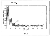
FIG. 2 illustrates an embodiment of amaximum error feedback 200 during a precoder training time, which may be obtained at an Exchange or a crosstalk precoder. Themaximum error feedback 200 may be represented by acurve 210. Thecurve 210 may comprise a plurality of received maximum error feedback values e max(i) for a plurality of transmitted pilot symbols i during the precoder training time. The received error feedback signal may be represented in complex format as:

FIG. 2 , the maximum error feedback value may decrease as the quantity of pilot symbols increases, e.g. as the training time increases. Additionally, the maximum error feedback value may converge to about a fixed value as the training time increases. -
FIG. 3 illustrates another embodiment of amaximum error feedback 300 during a precoder training time, which may be obtained at an Exchange or a crosstalk precoder. Themaximum error feedback 300 may be represented by acurve 310. Thecurve 310 may indicate a received maximum error feedback value e max(i) vs. the precoder training time (in seconds). Similar toFIG. 2 , the maximum error feedback value inFIG. 3 is found to decrease and converge as the training time increases. For example, e max(i) may be equal to about 0.16 at about the first second of training time and may decrease and converge to about 0.02 at about the tenth second of training time. - Typically, when a fixed quantity of bits is used to transmit the error feedback signal, the pilot symbols that have smaller error range and smaller maximum error feedback value may be represented with higher accuracy. Since the maximum error feedback may decrease as the training time increases (as shown in
FIG. 2 andFIG. 3 ), the quantization accuracy of the feedback error signal may increase as the training time increases when a fixed quantity of bits is used. For example, when about eight bits are used to transmit the error feedback signal, the quantization accuracy of the error feedback signal that has an error range between about -1 and about 1 may be equal to about 2-7 or about 0.0078. In comparison, using about the same quantity of bits, the quantization accuracy of the error feedback signal that has an error range between about -0.25 and about 0.25 may be substantially increased to about 2-9 or about 0.002. - If the quantity of quantization bits is reduced as the training time increases and the error range decreases, the quantization accuracy of the feedback error signal may remain about the same. For example, the quantization accuracy of the error feedback signal that has an error range between about -1 and about 1 may be equal to the quantization accuracy of the error feedback signal that has an error range between about -0.25 and about 0.25 when the quantity of quantization bits is reduced from about eight bits to about six bits. Reducing the quantity of quantization bits as the training time increases and the output of the crosstalk precoder converges may reduce overhead and bandwidth of the feedback channel. Additionally, as the quantity of used bits decrease, the training time may decrease and performance may improve.
- In an embodiment, a quantity of bits for representing error such that a full error range is preserved may be determined. The quantity of bits that may be used to represent the error feedback signal, Nr (i), may be determined based on a desired quantization accuracy, d, for the tones and the maximum error feedback in the pilot symbol e max(i), such as:

-
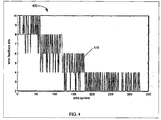
FIG. 4 illustrates an embodiment of a convergence in quantity oferror feedback bits 400 during a precoder training time. The error feedback bits may be sent from a CPE to an Exchange or a crosstalk precoder. The convergence in quantity oferror feedback bits 400 may be represented by acurve 410. Thecurve 410 may comprise a quantity of error feedback bits, Nr (i), for each of the transmitted pilot symbols i during the precoder training time. The quantity of error feedback bits may represent a plurality of error feedback signals, e.g. as received by a VTU-O in the Exchange. The quantity of error feedback bits Nr (i) may be determined based on a desired quantization accuracy, d, for the tones and the maximum error feedback in the pilot symbol e max(i), as shown in the equation above. Accordingly, the quantity of error feedback bits Nr (i) may be proportional to the maximum error feedback in the pilot symbol e max(i). The maximum error feedback in the pilot symbol e max(i) may be equal to about the maximum error feedback in the pilot symbol e max(i) inFIG. 2 . - In
FIG. 4 , the error feedback signal may be initially transmitted using about eight bits per error component and may have an error range between about -1 and about 1. The quantization accuracy d of the initial error feedback signal may be equal to about 2-7 or about 0.0078. The quantity of error feedback bits Nr (i) may then decrease as the quantity of pilot symbols increases, e.g. as the training time increases. The quantity of error feedback bits Nr (i) may converge to about four per error component as the training time increases. InFIG. 2 , it was shown that the maximum error feedback in the pilot symbol e max(i) may decrease and converge as the quantity of pilot symbols and the training time increase. Consequently, since the quantity of error feedback bits Nr (i) may be proportional to the maximum error feedback in the pilot symbol e max(i), the quantity of error feedback bits Nr (i) may also decrease and converge as the quantity of pilot symbols and the training time increase, as shown inFIG. 4 . The decrease in the quantity of error feedback bits Nr (i) may reduce the feedback data rate, increase precoder training time, and improve performance. - For example, at convergence, the quantity of total feedback bits in the transmitted pilot symbols may be equal to about 4.3x10⁶. This may be a reduction of about 71 percent in comparison to the case of training the precoder using a fixed quantity of bits at about eight bits per error component, where the quantity of total feedback bits may be of about 14.9x10⁶. Further, since the quantity of error feedback bits Nr (i) is calculated without substantially changing the quantization accuracy d of the initial error feedback signal, the decrease in the quantity of error feedback bits Nr (i) may not add substantial overhead in terms of accuracy for crosstalk reduction.
-
FIG. 5 illustrates an embodiment of aSNR improvement 500 during a precoder training time. TheSNR improvement 500 is shown for a plurality of pilot symbols received by an Exchange or a crosstalk precoder, e.g. as transmitted from the CPE. TheSNR improvements 500 may be represented by acurve 510. Thecurve 510 may comprise a SNR value for each of the transmitted pilot symbols i during the precoder training time. The pilot symbols may be transmitted by adjusting the quantity of error feedback bits, Nr (i), as shown incurve 410. As shown inFIG. 5 , the SNR value may increase and converge as the quantity of pilot symbols and the training time increase. Thecurve 510 may be compared to another curve 520, which may comprise the SNR values in an ideal precoder. The ideal precoder may eliminate the crosstalk in the line without substantial training time. As shown, the SNR value in thecurve 510 may reach about the same SNR value of the curve 520 at the convergence point, e.g. at about 400 transmitted pilot symbols. - The
curve 510 may also be compared to anothercurve 530, which may comprise the SNR values for the transmitted pilot symbols i using about eight bits per error component. The quantity of feedback bits incurve 530 may be fixed for all the transmitted pilot symbols. This fixed quantity of bits may be equal to the initial quantity of bits per error component incurve 510 and to about twice the quantity of bits at the convergence point ofcurve 510. The twocurves - In another embodiment, the quantity of error feedback bits may be kept fixed during the training time and the quantization accuracy, e.g. per error component, may be increased. As such, the quantization accuracy, d, may be adjusted based on the quantity of error feedback bits, Nr (i), and the maximum error feedback in the pilot symbols, e max(i), such as:

- In an embodiment, to adjust the quantization accuracy of the error feedback signals, an error vector (per error component) may be scaled to guarantee using substantially the full the error range. First, a scaling factor SQ (i) may be selected from a set of scaling factors, e.g. (1,2,..., 256). The scaling factor may be selected such that SQ (i). e max(i) ≤ 1, e.g. for a quantization range between about -1 and about 1, to avoid clipping the error feedback signal. The error components (e.g. real and imaginary components) may then be scaled by the scaling factor, such as:


e x ande y are the scaled error vectors. The quantization accuracy may be increased by scaling the error vectors before digitizing or representing the error feedback signals in bits. - For instance, the error feedback signal may be represented based on a quantization format proposed by the International Telecommunication Union (ITU) Telecommunication Standardization Sector (ITU-T) document C-91, which is incorporated herein by reference. Thus, the error feedback signal may be represented in complex format as:


- In an embodiment, the VTU-R at the CPE may indicate the used scaling factor SQ (i) to the VTU-O at the Exchange. The VTU-R may send an error feedback message (e.g. R-ERROR_FEEDBACK) that comprises the scaling factor SQ (i) to the VTU-O. The same scaling factor may be used for all the tones in a pilot symbol, and hence a single field in the error feedback message may be needed to indicate the scaling factor SQ (i). For instance, the error feedback message R-ERROR_FEEDBACK in Table 10-4 of the ITU-T standard G.vector, which is incorporated herein by reference, may be modified to include a field "Quantization Scaling Factor" (e.g. Field #3), as shown below.
Table 1: A Modified Version of Table 10-4 of the ITU-T Standard G.vector. Field Name Format 1 Message Descriptor Message Code 2 Frequency Band ID 1 byte 3 Quantization Scaling Factor 1 byte 4 Error Vector Nbytes bytes - When a LMS algorithm is used to obtain the precoding matrix and train the crosstalk precoder, the error in the pilot symbols and accordingly the error feedback signals may be reduced in an asymptotic manner, e.g. may converge to a level or value. The convergence level may be dependent on the level of the quantization noise in the error feedback signal. Scaling the error vector may reduce the quantization noise and increase the LMS step size, which may reduce the asymptotic error (or convergence level) and increase the quantization accuracy. Additionally, reducing the LMS step size may increase the convergence rate and reduce the precoder training time.
-
FIG. 6 illustrates an embodiment of adata rate improvement 600 during a precoder training time. Thedata rate improvement 600 is shown for simulated pilot symbols in a selected line. The selected line may be bonded with a plurality of other lines, including about 14 legacy lines and about 17 active vectored lines. Specifically, a second phase (e.g. R-P-VECTOR2) of crosstalk precoder initialization was simulated, where the precoder may learn to cancel crosstalk from the active lines into the selected line. According to the ITU-T document C-140 (which is incorporated herein by reference), the second phase may be the longest phase of crosstalk precoder initialization and therefore may substantially determine the total initialization time for the precoder. - The
data rate improvement 600 may be represented by acurve 610. Thecurve 610 may comprise a data rate value for each of the transmitted pilot symbols during the precoder training time. The pilot symbols may be transmitted by adjusting the error vector and hence the accuracy of the error feedback signals. The error vector was adjusted by selecting a scaling factor value from thevalues FIG. 6 , the data rate value may increase and converge as the training time increases. Thecurve 610 may be compared to anothercurve 620, which may comprise the data rate values in an ideal precoder, e.g. which may cancel the crosstalk in the line without substantial training time. The data rate value in thecurve 610 may reach about 140 megabits per second (Mbps) after about eight seconds, which may be substantially close to the data rate value of thecurve 620.Table 2 Parameter Value Loop type arrayed waveguide grating (AWG) 26 Number of lines Total = 32; 14 legacy + 18 vectored (17 busy, 1 joining) Length of orthogonal sequence 32 (duration = 2 seconds) Loop length 300 meters Symbol rate 4000 symbols/second Transmit power -60 decibel (dBm)/Hertz (Hz) Noise -135 dBm/Hz Bandplan 17a Far-end crosstalk (FEXT) model Alcatel-Lucent (NIPP-NAI 2008-010R1) Back channel Extended SOC channel with 4 or 8 bits per complex error sample Coding gain 2 dB SNR margin 6 dB Bit error rate (BER) 10-7 Valid scaling factors 1,2,4,8,16,32,64,128,256 - The
curve 610 may also be compared tocurves curve 630 was obtained using a LMS step size µ equal to about 0.01, and thecurve 640 was obtained using a LMS step size µ equal to about 0.02. The data rate value in thecurve 630 reaches about 140 Mbps after about 20 seconds. The improvement in the training time of thecurve 610 in comparison to thecurve 630 may be equal to about 60 percent Although thecurve 640 may reach convergence at about the same time as thecurve 610, the data rate value in thecurve 640 at convergence may be about 131 Mbps, which is substantially lower than thecurve 610 that has a data rate value at about 140 Mbps. - Adjusting the LMS step size and using conventional quantization (e.g. fixed error scaling) may improve the training time of the precoder at the expense of accuracy and achievable data rate, as shown in the
curves curve 610. Adjusting the scaling factor in the error feedback signals may guarantee that the error values occupy substantially the entire error range, which may improve the accuracy in representing the errors and hence increase the achievable data rate. Representing the error feedback signals more accurately may also cause faster convergence in the output of the precoder, e.g. using the LMS algorithm, and therefore reduce the training time. -
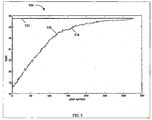
FIG. 7 illustrates another embodiment of adata rate improvement 700 during a precoder training time. Thedata rate improvement 700 is shown for simulated pilot symbols in a joining line, which may be configured substantially similar to the pilot symbols inFIG. 6 . However, inFIG. 7 , the quantity of bits used to represent the pilot symbols during the training time is fixed at about four bits. Thedata rate improvement 700 may be represented by acurve 710. Thecurve 710 may comprise a data rate value for each of the transmitted pilot symbols during the precoder training time. The pilot symbols may be transmitted by adjusting the error vector and hence the accuracy of the error feedback signals. The error vector was adjusted by selecting a scaling factor value from thevalues curve 710 was obtained using a LMS step size µ equal to about 0.01. As shown inFIG. 7 , the data rate value may increase and converge as the training time increases. Thecurve 710 may be compared to anothercurve 720, which may comprise the data rate values in an ideal precoder. The data rate value in thecurve 710 may reach about 143 Mbps after about 24 seconds, which may be substantially close to the data rate value of thecurve 720. - The
curve 710 may also be compared tocurves curve 730 was obtained using an LMS step size µ equal to about 0.01, and thecurve 740 was obtained using a smaller LMS step size µ equal to about 0.003. The data rate value in thecurve 730 may reach about 90 Mbps after about ten seconds, which shows a faster training time in comparison to thecurve 710. However, thecurve 730 may achieve a substantially lower data rate at convergence than thecurve 710. In comparison to thecurve 730, the data rate value in thecurve 740 may reach about 118 Mbps after about 50 seconds, which shows an improvement in achievable data rate at the expense of additional training time. Thus, thecurve 710 shows improvement in both training time and achievable data rate than thecurves -
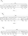
FIG. 8 illustrates an embodiment of anerror feedback message 800, which may be sent from the CPE to the Exchange. Theerror feedback message 800 may comprise a plurality of error feedback values 810, which may correspond to a plurality of tones in a pilot symbol. Eacherror feedback value 810 may comprise areal error component 812 and animaginary error component 814. For example, theerror feedback message 800 may comprise K real error components 812 (e.g. ex (1,i), ex (2,i), ..., ex (K,i)) and K imaginary error components 814 (e.g. ey (1,i), ey (2,i), ..., ey (K,i)) for K tones in the pilot symbol, where K is an integer. Additionally, theerror feedback message 800 may comprise a number ofbits 820 per error component The number ofbits 820 may indicate the quantity of quantization bits Nr (i) that is used to represent thereal error component 812 and similarly theimaginary component 814 for each tone. -
FIG. 9 illustrates another embodiment of anerror feedback message 900, which may be sent from the CPE to the Exchange. Theerror feedback message 900 may comprise a plurality of error feedback values 910, which may correspond to a plurality of tones in a pilot symbol. Eacherror feedback value 910 may comprise areal error component 912 and animaginary error component 914. For example, theerror feedback message 900 may comprise K real error components 912 (e.g. ex (1,i), ex (2,i), ..., ex (K,i)) and K imaginary error components 914 (e.g. ey (1,i), ey (2,i), ..., ey (K,i)) for K tones in the pilot symbol, where K is an integer. Additionally, theerror feedback message 900 may comprise aquantization accuracy 920. Thequantization accuracy 920 may indicate the quantization accuracy d of thereal error component 912 and similarly theimaginary component 914 for each tone. -
FIG. 10 illustrates another embodiment of anerror feedback message 1000, which may be sent from the CPE to the Exchange. Theerror feedback message 1000 may comprise a plurality of error feedback values 1010, which may correspond to a plurality of tones in a pilot symbol. Eacherror feedback value 1010 may comprise areal error component 1012 and animaginary error component 1014. For example, theerror feedback message 1000 may comprise K real error components 1012 (e.g. ex (1,i), ex (2,i), ..., ex (K,i)) and K imaginary error components 1014 (e.g. ey (1,i), ey (2,i), ..., ey (K,i)) for K tones in the pilot symbol, where K is an integer. Additionally, theerror feedback message 1000 may comprise a number ofbits 1020 per error component and aquantization accuracy 1030. The number ofbits 1020 and thequantization accuracy 1030 may indicate the quantity of quantization bits Nr (i) and the quantization accuracy d, respectively, for thereal error component 1012 and similarly theimaginary component 1014 for each tone. -
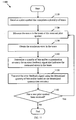
FIG. 11 illustrates an embodiment of an errorfeedback signaling method 1100, which may be used during a crosstalk precoder initialization or training time. The errorfeedback signaling method 1100 may be established between a CPE and an Exchange or a crosstalk precoder coupled to the Exchange. Themethod 1100 may begin atblock 1110, where a pilot symbol that comprises a plurality of tones may be received. For example, the pilot symbol may be transmitted by a VTU-O at the Exchange and received by a VTU-R at the CPE via a subscriber line. Next, atblock 1120, the errors in the tones of the received pilot symbol may be measured. For example, the VTU-R may measure the error in each tone, which may result from crosstalk in the subscriber line from adjacent or other subscriber lines. Atblock 1130, the maximum error in the tones may be obtained. For example, the maximum error in the plot symbol e max(i) may be the maximum error component in the tones, such as from a plurality of real and imaginary error components based on equation (4). - At
block 1140, a quantity of bits and/or a quantization accuracy may be determined for an error feedback signal that indicates the measured errors in the tones. For instance, the quantity of bits Nr (i) may be determined based on a predetermined accuracy d and the maximum error e max(i), e.g. using equation (5). As such, the quantity of bits for the error feedback signal may be reduced as the errors in the tones decrease to reduce the training time of the crosstalk precoder. Alternatively, the quantization accuracy d may be determined based on a fixed quantity of bits Nr (i) and the maximum error e max(i), e.g. using equation (6). Accordingly, the error vector for the error feedback signal may be scaled, e.g. using a scaling factor SQ (i) and equations (7a) and (7b). As such, the quantization accuracy for the error feedback signal may be increased to improve system performance by increasing the achievable data rate after training the crosstalk precoder. In other embodiments, both the quantity of bits and the quantization accuracy may be adjusted based on the maximum error e max(i) to achieve an acceptable or desired balance (or tradeoff) between the training time and the achievable data rate. - Next, at
bock 1150, the error feedback signal may be transmitted using the determined quantity of bits and/or based on the determined quantization accuracy. For example, the CPE may send an error feedback message to the Exchange, such us theerror feedback message 800, theerror feedback message 900, or theerror feedback message 1000. In some embodiments, the error feedback message may be configured similar to the R-ERROR_FEEDBACK message in Table 10-4 of the ITU-T standard G.vector and comprise a field "Quantization Scaling Factor" that indicates the quantization accuracy. Atblock 1160, themethod 1100 may determine if a next pilot symbol has been received. If the condition inblock 1160 is met, themethod 1100 may return to block 1120 to measure the errors in the next pilot symbol and transmit an error feedback signal accordingly. Otherwise, themethod 1100 may end. - The components described above may be operated in conjunction with any general-purpose network component, such as a computer or network component with sufficient processing power, memory resources, and network throughput capability to handle the necessary workload placed upon it
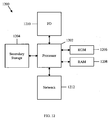
FIG. 12 illustrates a typical, general-purpose network component 1200 suitable for implementing one or more embodiments of the components disclosed herein. Thenetwork component 1200 may include a processor 1202 (which may be referred to as a central processor unit or CPU) that is in communication with any memory devices includingsecondary storage 1204, read only memory (ROM) 1206, random access memory (RAM) 1208, input/output (I/O)devices 1210, andnetwork connectivity devices 1212, or combinations thereof. Theprocessor 1202 may be implemented as one or more CPU chips, or may be part of one or more application specific integrated circuits (ASICs). - The
secondary storage 1204 is typically comprised of one or more disk drives or tape drives and is used for non-volatile storage of data and as an over-flow data storage device ifRAM 1208 is not large enough to hold all working data.Secondary storage 1204 may be used to store programs that are loaded intoRAM 1208 when such programs are selected for execution. TheROM 1206 is used to store instructions and perhaps data that are read during program execution.ROM 1206 is a non-volatile memory device that typically has a small memory capacity relative to the larger memory capacity ofsecondary storage 1204. TheRAM 1208 is used to store volatile data and perhaps to store instructions. Access to bothROM 1206 andRAM 1208 is typically faster than tosecondary storage 1204. - At least one embodiment is disclosed and variations, combinations, and/or modifications of the embodiment(s) and/or features of the embodiment(s) made by a person having ordinary skill in the art are within the scope of the disclosure. The present invention is defined and limited solely by the scope of appended claims 1-8. Where numerical ranges or limitations are expressly stated, such express ranges or limitations should be understood to include iterative ranges or limitations of like magnitude falling within the expressly stated ranges or limitations (e.g., from about 1 to about 10 includes, 2, 3,4, etc.; greater than 0.10 includes 0.11, 0.12, 0.13, etc.). For example, whenever a numerical range with a lower limit, Rl, and an upper limit, Ru, is disclosed, any number falling within the range is specifically disclosed. In particular, the following numbers within the range are specifically disclosed: R = Rl + k * (Ru - Rl), wherein k is a variable ranging from 1 percent to 100 percent with a 1 percent increment, i.e., k is 1 percent, 2 percent, 3 percent, 4 percent, 5 percent, ..., 50 percent, 51 percent, 52 percent, ..., 95 percent, 96 percent, 97 percent, 98 percent, 99 percent, or 100 percent Moreover, any numerical range defined by two R numbers as defined in the above is also specifically disclosed.
- In addition, techniques, systems, subsystems, and methods described and illustrated in the various embodiments as discrete or separate may be combined or integrated with other systems, modules, techniques, or methods without departing from the scope of the present disclosure. Other items shown or discussed as coupled or directly coupled or communicating with each other may be indirectly coupled or communicating through some interface, device, or intermediate component whether electrically, mechanically, or otherwise. The present invention is defined and limited only by the scope of appended claims 1-8.
Claims (8)
- An apparatus comprising:a transceiver coupled to a digital subscriber line, DSL, (106) between an exchange site (102) and a customer premise equipment, CPE, (104) and configured to send a feedback error message (800, 900, 1000) to train a crosstalk precoder (108) coupled to the exchange site (102),wherein the feedback error message (800, 900, 1000) comprisesa first field for carrying a plurality of error components (810, 910, 1010), wherein the error components correspond to a plurality of tones in a received pilot symbol, anda second field for carrying information (820, 1020) which indicates a quantity of bits per error component.
- The apparatus of claim 1, wherein the error components comprise a real error component (812, 912, 1012) and an imaginary error component (814, 914, 1014) for each one of the tones.
- The apparatus of claim 1 or 2, wherein the exchange site (102) comprises a very high bit rate DSL , VDSL, transceiver office unit, VTU-O, that is configured to transmit the pilot symbol to the CPE.
- The apparatus of claim 1 or 2, wherein the transceiver is configured to determine the quantity of bits per error component, the quantization accuracy per error component, or both, and transmit the error feedback message (800, 900, 1000) to the exchange site (102).
- The apparatus ofone of the claims 1 to 4, wherein the error components correspond to a level of crosstalk error in the DSL.
- The apparatus of claim 5, wherein the crosstalk precoder is trained based on the error feedback message and using a least mean square, LMS, algorithm.
- A method comprising:receiving, by a first transceiver, a feedback error message from a second transceiver, wherein the second transceiver coupled to a digital subscriber line, DSL, (106) between an exchange site (102) and a customer premise equipment, CPE, (104),wherein the feedback error message (800, 900, 1000) comprisesa first field for carrying a plurality of error components (810, 910, 1010), wherein the error components correspond to a plurality of tones in a received pilot symbol, anda second field for carrying information (820, 1020) which indicates a quantity of bits per error component.
- The method of claim 7, wherein the error components (810, 910,1010) comprise a real error component (812, 912,1012) and an imaginary error component (814, 914, 1014) for each one of the tones.
Priority Applications (3)
| Application Number | Priority Date | Filing Date | Title |
|---|---|---|---|
| EP16171613.9A EP3091688B1 (en) | 2009-01-30 | 2010-02-01 | Reduction of feedback overhead during the initialization of crosstalk precoders in dsl systems |
| PL16171613T PL3091688T3 (en) | 2009-01-30 | 2010-02-01 | Reduction of feedback overhead during the initialization of crosstalk precoders in dsl systems |
| EP18181017.7A EP3402116B1 (en) | 2009-01-30 | 2010-02-01 | Method and apparatus for reducing feedback overhead |
Applications Claiming Priority (4)
| Application Number | Priority Date | Filing Date | Title |
|---|---|---|---|
| US14888709P | 2009-01-30 | 2009-01-30 | |
| US14882709P | 2009-01-30 | 2009-01-30 | |
| US12/690,757 US8750492B2 (en) | 2009-01-30 | 2010-01-20 | Reducing the feedback overhead during crosstalk precoder initialization |
| EP10735481.3A EP2286574B1 (en) | 2009-01-30 | 2010-02-01 | Method and apparatus for reducing feedback overhead during crosstalk precoder initialization |
Related Parent Applications (2)
| Application Number | Title | Priority Date | Filing Date |
|---|---|---|---|
| EP10735481.3A Division-Into EP2286574B1 (en) | 2009-01-30 | 2010-02-01 | Method and apparatus for reducing feedback overhead during crosstalk precoder initialization |
| EP10735481.3A Division EP2286574B1 (en) | 2009-01-30 | 2010-02-01 | Method and apparatus for reducing feedback overhead during crosstalk precoder initialization |
Related Child Applications (3)
| Application Number | Title | Priority Date | Filing Date |
|---|---|---|---|
| EP18181017.7A Division EP3402116B1 (en) | 2009-01-30 | 2010-02-01 | Method and apparatus for reducing feedback overhead |
| EP16171613.9A Division EP3091688B1 (en) | 2009-01-30 | 2010-02-01 | Reduction of feedback overhead during the initialization of crosstalk precoders in dsl systems |
| EP16171613.9A Division-Into EP3091688B1 (en) | 2009-01-30 | 2010-02-01 | Reduction of feedback overhead during the initialization of crosstalk precoders in dsl systems |
Publications (2)
| Publication Number | Publication Date |
|---|---|
| EP2858294A1 EP2858294A1 (en) | 2015-04-08 |
| EP2858294B1 true EP2858294B1 (en) | 2016-08-24 |
Family
ID=42395105
Family Applications (4)
| Application Number | Title | Priority Date | Filing Date |
|---|---|---|---|
| EP16171613.9A Active EP3091688B1 (en) | 2009-01-30 | 2010-02-01 | Reduction of feedback overhead during the initialization of crosstalk precoders in dsl systems |
| EP10735481.3A Active EP2286574B1 (en) | 2009-01-30 | 2010-02-01 | Method and apparatus for reducing feedback overhead during crosstalk precoder initialization |
| EP18181017.7A Active EP3402116B1 (en) | 2009-01-30 | 2010-02-01 | Method and apparatus for reducing feedback overhead |
| EP14200354.0A Active EP2858294B1 (en) | 2009-01-30 | 2010-02-01 | Feedback overhead reduction during crosstalk precoder initialization in DSL systems |
Family Applications Before (3)
| Application Number | Title | Priority Date | Filing Date |
|---|---|---|---|
| EP16171613.9A Active EP3091688B1 (en) | 2009-01-30 | 2010-02-01 | Reduction of feedback overhead during the initialization of crosstalk precoders in dsl systems |
| EP10735481.3A Active EP2286574B1 (en) | 2009-01-30 | 2010-02-01 | Method and apparatus for reducing feedback overhead during crosstalk precoder initialization |
| EP18181017.7A Active EP3402116B1 (en) | 2009-01-30 | 2010-02-01 | Method and apparatus for reducing feedback overhead |
Country Status (7)
| Country | Link |
|---|---|
| US (3) | US8750492B2 (en) |
| EP (4) | EP3091688B1 (en) |
| CN (3) | CN104143998B (en) |
| ES (1) | ES2602959T3 (en) |
| PL (2) | PL3091688T3 (en) |
| PT (1) | PT2858294T (en) |
| WO (1) | WO2010085921A1 (en) |
Families Citing this family (22)
| Publication number | Priority date | Publication date | Assignee | Title |
|---|---|---|---|---|
| US8750492B2 (en) | 2009-01-30 | 2014-06-10 | Futurewei Technologies, Inc. | Reducing the feedback overhead during crosstalk precoder initialization |
| US8711760B2 (en) * | 2010-03-26 | 2014-04-29 | Intel Corporation | Method and apparatus to adjust received signal |
| US8537655B2 (en) * | 2011-01-28 | 2013-09-17 | Alcatel Lucent | Multiplicative updating of precoder or postcoder matrices for crosstalk control in a communication system |
| EP2681860B1 (en) | 2011-03-02 | 2016-02-24 | Adtran, Inc. | Systems and methods for bypassing failed line cards in multi-card vectoring groups |
| WO2012167537A1 (en) * | 2011-11-03 | 2012-12-13 | 华为技术有限公司 | Method, apparatus and system for reducing interference in digital subscriber line |
| EP2690805B1 (en) * | 2012-07-23 | 2020-05-27 | Lantiq Beteiligungs-GmbH & Co.KG | Spectrum management and timing optimization over multiple distribution points |
| US8989063B2 (en) * | 2012-07-25 | 2015-03-24 | Futurewei Technologies, Inc. | Time division multiple access far end crosstalk channel estimation |
| WO2014100991A1 (en) | 2012-12-26 | 2014-07-03 | 华为技术有限公司 | Method and device for line initialization |
| EP2779475B1 (en) * | 2013-03-14 | 2016-07-27 | Alcatel Lucent | Error feedback with detected constellation point |
| CN106464764B (en) * | 2013-05-05 | 2020-01-10 | 领特贝特林共有限责任两合公司 | Time sharing for low power modes |
| KR101911809B1 (en) * | 2013-05-13 | 2018-10-25 | 란티크 베테일리궁스-게엠베하 운트 코 카게 | Special operations channel in vectored systems |
| GB2528221B (en) * | 2013-06-18 | 2016-09-14 | Arris Entpr Inc | Quality check identifying source of service issue |
| CN106605370B (en) * | 2014-03-25 | 2021-05-11 | 领特贝特林共有限责任两合公司 | Apparatus and method for suppressing interference |
| CN110266430B (en) * | 2014-04-30 | 2021-07-30 | 中兴通讯股份有限公司 | Feedback information processing method, device and system |
| CN105306389B (en) * | 2014-06-25 | 2019-03-22 | 中兴通讯股份有限公司 | Data processing method and device |
| CN105591710B (en) * | 2014-10-20 | 2018-07-13 | 中国电信股份有限公司 | Methods, devices and systems for vectored DSL fast initialization |
| US10141976B2 (en) * | 2015-02-24 | 2018-11-27 | Lantiq Beteiligungs-GmbH & Co. KG | Crosstalk mitigation |
| CN107438987B (en) * | 2015-03-31 | 2020-10-23 | 英国电讯有限公司 | Method and system for transmitting data between transmitter and receiver, and transceiver |
| US9948371B2 (en) * | 2015-05-11 | 2018-04-17 | Futurewei Technologies, Inc. | Multi-user multiple-input and multiple-output for digital subscriber line |
| US11290150B2 (en) * | 2017-05-03 | 2022-03-29 | Assia Spe, Llc | Systems and methods for implementing high-speed waveguide transmission over wires |
| CN109600179B (en) * | 2017-09-30 | 2021-04-27 | 富士通株式会社 | Method and device for estimating linear crosstalk between channels and receiver |
| CN109728837B (en) * | 2017-10-30 | 2020-11-17 | 桐乡市定邦信息技术有限公司 | Method, device and system for counteracting crosstalk signals |
Family Cites Families (13)
| Publication number | Priority date | Publication date | Assignee | Title |
|---|---|---|---|---|
| US6532277B2 (en) * | 1999-11-12 | 2003-03-11 | Qwest Communications International Inc. | Method for controlling DSL transmission power |
| CN101123594B (en) * | 2006-08-08 | 2012-07-25 | 上海贝尔阿尔卡特股份有限公司 | System, device and method for MIMO base band processing |
| EP2055014B1 (en) * | 2006-08-25 | 2013-03-06 | Ikanos Technology Ltd. | Systems and methods for mimo precoding in an xdsl system |
| US20080123755A1 (en) * | 2006-09-18 | 2008-05-29 | Axel Clausen | Method and apparatus for data transmission |
| CN101232356A (en) * | 2007-01-24 | 2008-07-30 | 华为技术有限公司 | Precoding method, system and apparatus in MIMO system |
| US20080192852A1 (en) * | 2007-02-12 | 2008-08-14 | Mark Kent | Method and system for an alternating channel delta quantizer for 2x2 mimo pre-coders with finite rate channel state information feedback |
| US7843990B2 (en) | 2007-04-09 | 2010-11-30 | Alcatel-Lucent Usa Inc. | Determining a channel matrix by measuring interference |
| US8830812B2 (en) | 2007-08-31 | 2014-09-09 | Alcatel Lucent | Optimizing precoder settings using average SINR reports for groups of tones |
| US8300518B2 (en) * | 2008-04-01 | 2012-10-30 | Alcatel Lucent | Fast seamless joining of channels in a multi-channel communication system |
| EP2136477B1 (en) * | 2008-06-16 | 2011-08-03 | Alcatel Lucent | Device and associated method for crosstalk estimation |
| US8750492B2 (en) | 2009-01-30 | 2014-06-10 | Futurewei Technologies, Inc. | Reducing the feedback overhead during crosstalk precoder initialization |
| US8514687B2 (en) * | 2010-10-29 | 2013-08-20 | Alcatel Lucent | Efficient generation of compensated signals for crosstalk control in a communication system |
| US20120236915A1 (en) * | 2011-03-18 | 2012-09-20 | Nuzman Carl J | Crosstalk control methods and apparatus utilizing compressed representation of compensation coefficients |
-
2010
- 2010-01-20 US US12/690,757 patent/US8750492B2/en active Active
- 2010-02-01 CN CN201410394835.XA patent/CN104143998B/en active Active
- 2010-02-01 CN CN201410397923.5A patent/CN104253629B/en active Active
- 2010-02-01 PT PT142003540T patent/PT2858294T/en unknown
- 2010-02-01 EP EP16171613.9A patent/EP3091688B1/en active Active
- 2010-02-01 PL PL16171613T patent/PL3091688T3/en unknown
- 2010-02-01 EP EP10735481.3A patent/EP2286574B1/en active Active
- 2010-02-01 EP EP18181017.7A patent/EP3402116B1/en active Active
- 2010-02-01 EP EP14200354.0A patent/EP2858294B1/en active Active
- 2010-02-01 CN CN201080001758.7A patent/CN102217294B/en active Active
- 2010-02-01 ES ES14200354.0T patent/ES2602959T3/en active Active
- 2010-02-01 PL PL14200354T patent/PL2858294T3/en unknown
- 2010-02-01 WO PCT/CN2010/070445 patent/WO2010085921A1/en active Application Filing
-
2014
- 2014-04-28 US US14/263,149 patent/US9462116B2/en active Active
-
2016
- 2016-09-19 US US15/268,754 patent/US10063278B2/en active Active
Also Published As
| Publication number | Publication date |
|---|---|
| CN102217294A (en) | 2011-10-12 |
| CN104143998B (en) | 2016-07-27 |
| ES2602959T3 (en) | 2017-02-23 |
| US20140233722A1 (en) | 2014-08-21 |
| CN104143998A (en) | 2014-11-12 |
| CN104253629A (en) | 2014-12-31 |
| EP3402116A1 (en) | 2018-11-14 |
| WO2010085921A1 (en) | 2010-08-05 |
| PL2858294T3 (en) | 2017-03-31 |
| EP3091688A1 (en) | 2016-11-09 |
| EP2286574A4 (en) | 2011-11-09 |
| US20100195817A1 (en) | 2010-08-05 |
| US20170005700A1 (en) | 2017-01-05 |
| EP2286574B1 (en) | 2015-04-08 |
| EP2858294A1 (en) | 2015-04-08 |
| US9462116B2 (en) | 2016-10-04 |
| CN104253629B (en) | 2017-11-24 |
| EP2286574A1 (en) | 2011-02-23 |
| EP3402116B1 (en) | 2019-12-25 |
| PL3091688T3 (en) | 2019-03-29 |
| CN102217294B (en) | 2014-07-16 |
| US8750492B2 (en) | 2014-06-10 |
| PT2858294T (en) | 2016-10-13 |
| EP3091688B1 (en) | 2018-09-26 |
| US10063278B2 (en) | 2018-08-28 |
Similar Documents
| Publication | Publication Date | Title |
|---|---|---|
| US10063278B2 (en) | Reducing the feedback overhead during crosstalk precoder initialization | |
| EP2858255B1 (en) | Method for robust crosstalk precoder training in channels with impulse noise | |
| US8194767B2 (en) | Systems and methods for MIMO precoding in an xDSL system | |
| US8270523B2 (en) | Crosstalk control method and apparatus using a bandwidth-adaptive precoder interface | |
| US9985685B2 (en) | Power spectrum density optimization | |
| US20110007623A1 (en) | Method for Estimating the Strength of a Crosstalk Channel | |
| US8964884B2 (en) | Power control in linear precoder design for MIMO DSL transmission | |
| CN103004099B (en) | Method, apparatus and system for reducing interference in digital subscriber line | |
| EP2283639B1 (en) | Dynamic transmitter noise level adjustment for digital subscriber line systems | |
| US8406416B2 (en) | Configuring virtual noise parameters of very high-speed digital subscriber line | |
| US8811600B2 (en) | Optimizing the transmit power spectrum density (PSD) of a remotely deployed line to ensure spectral compatibility | |
| Strobel | Channel Modeling and Physical Layer Optimization in Copper Line Networks | |
| US8665932B2 (en) | Low complexity technique for digital subscriber line (DSL) power control |
Legal Events
| Date | Code | Title | Description |
|---|---|---|---|
| PUAI | Public reference made under article 153(3) epc to a published international application that has entered the european phase |
Free format text: ORIGINAL CODE: 0009012 |
|
| 17P | Request for examination filed |
Effective date: 20141225 |
|
| AC | Divisional application: reference to earlier application |
Ref document number: 2286574 Country of ref document: EP Kind code of ref document: P |
|
| AK | Designated contracting states |
Kind code of ref document: A1 Designated state(s): AT BE BG CH CY CZ DE DK EE ES FI FR GB GR HR HU IE IS IT LI LT LU LV MC MK MT NL NO PL PT RO SE SI SK SM TR |
|
| R17P | Request for examination filed (corrected) |
Effective date: 20151008 |
|
| RBV | Designated contracting states (corrected) |
Designated state(s): AT BE BG CH CY CZ DE DK EE ES FI FR GB GR HR HU IE IS IT LI LT LU LV MC MK MT NL NO PL PT RO SE SI SK SM TR |
|
| GRAP | Despatch of communication of intention to grant a patent |
Free format text: ORIGINAL CODE: EPIDOSNIGR1 |
|
| RIC1 | Information provided on ipc code assigned before grant |
Ipc: H04M 3/34 20060101ALI20160125BHEP Ipc: H04M 3/30 20060101ALI20160125BHEP Ipc: H04L 25/02 20060101ALI20160125BHEP Ipc: H04B 3/32 20060101ALI20160125BHEP Ipc: H04M 3/22 20060101ALI20160125BHEP Ipc: H04M 3/00 20060101ALI20160125BHEP Ipc: H04L 5/00 20060101AFI20160125BHEP |
|
| INTG | Intention to grant announced |
Effective date: 20160222 |
|
| GRAS | Grant fee paid |
Free format text: ORIGINAL CODE: EPIDOSNIGR3 |
|
| GRAA | (expected) grant |
Free format text: ORIGINAL CODE: 0009210 |
|
| AC | Divisional application: reference to earlier application |
Ref document number: 2286574 Country of ref document: EP Kind code of ref document: P |
|
| AK | Designated contracting states |
Kind code of ref document: B1 Designated state(s): AT BE BG CH CY CZ DE DK EE ES FI FR GB GR HR HU IE IS IT LI LT LU LV MC MK MT NL NO PL PT RO SE SI SK SM TR |
|
| REG | Reference to a national code |
Ref country code: GB Ref legal event code: FG4D |
|
| REG | Reference to a national code |
Ref country code: CH Ref legal event code: EP |
|
| REG | Reference to a national code |
Ref country code: AT Ref legal event code: REF Ref document number: 823920 Country of ref document: AT Kind code of ref document: T Effective date: 20160915 |
|
| REG | Reference to a national code |
Ref country code: IE Ref legal event code: FG4D |
|
| REG | Reference to a national code |
Ref country code: DE Ref legal event code: R096 Ref document number: 602010035918 Country of ref document: DE |
|
| REG | Reference to a national code |
Ref country code: PT Ref legal event code: SC4A Ref document number: 2858294 Country of ref document: PT Date of ref document: 20161013 Kind code of ref document: T Free format text: AVAILABILITY OF NATIONAL TRANSLATION Effective date: 20161006 |
|
| REG | Reference to a national code |
Ref country code: NL Ref legal event code: FP |
|
| REG | Reference to a national code |
Ref country code: SE Ref legal event code: TRGR |
|
| REG | Reference to a national code |
Ref country code: LT Ref legal event code: MG4D |
|
| REG | Reference to a national code |
Ref country code: FR Ref legal event code: PLFP Year of fee payment: 8 |
|
| REG | Reference to a national code |
Ref country code: AT Ref legal event code: MK05 Ref document number: 823920 Country of ref document: AT Kind code of ref document: T Effective date: 20160824 |
|
| PG25 | Lapsed in a contracting state [announced via postgrant information from national office to epo] |
Ref country code: LT Free format text: LAPSE BECAUSE OF FAILURE TO SUBMIT A TRANSLATION OF THE DESCRIPTION OR TO PAY THE FEE WITHIN THE PRESCRIBED TIME-LIMIT Effective date: 20160824 Ref country code: FI Free format text: LAPSE BECAUSE OF FAILURE TO SUBMIT A TRANSLATION OF THE DESCRIPTION OR TO PAY THE FEE WITHIN THE PRESCRIBED TIME-LIMIT Effective date: 20160824 Ref country code: NO Free format text: LAPSE BECAUSE OF FAILURE TO SUBMIT A TRANSLATION OF THE DESCRIPTION OR TO PAY THE FEE WITHIN THE PRESCRIBED TIME-LIMIT Effective date: 20161124 Ref country code: HR Free format text: LAPSE BECAUSE OF FAILURE TO SUBMIT A TRANSLATION OF THE DESCRIPTION OR TO PAY THE FEE WITHIN THE PRESCRIBED TIME-LIMIT Effective date: 20160824 |
|
| REG | Reference to a national code |
Ref country code: ES Ref legal event code: FG2A Ref document number: 2602959 Country of ref document: ES Kind code of ref document: T3 Effective date: 20170223 |
|
| PG25 | Lapsed in a contracting state [announced via postgrant information from national office to epo] |
Ref country code: AT Free format text: LAPSE BECAUSE OF FAILURE TO SUBMIT A TRANSLATION OF THE DESCRIPTION OR TO PAY THE FEE WITHIN THE PRESCRIBED TIME-LIMIT Effective date: 20160824 Ref country code: LV Free format text: LAPSE BECAUSE OF FAILURE TO SUBMIT A TRANSLATION OF THE DESCRIPTION OR TO PAY THE FEE WITHIN THE PRESCRIBED TIME-LIMIT Effective date: 20160824 |
|
| PG25 | Lapsed in a contracting state [announced via postgrant information from national office to epo] |
Ref country code: RO Free format text: LAPSE BECAUSE OF FAILURE TO SUBMIT A TRANSLATION OF THE DESCRIPTION OR TO PAY THE FEE WITHIN THE PRESCRIBED TIME-LIMIT Effective date: 20160824 Ref country code: EE Free format text: LAPSE BECAUSE OF FAILURE TO SUBMIT A TRANSLATION OF THE DESCRIPTION OR TO PAY THE FEE WITHIN THE PRESCRIBED TIME-LIMIT Effective date: 20160824 |
|
| REG | Reference to a national code |
Ref country code: DE Ref legal event code: R097 Ref document number: 602010035918 Country of ref document: DE |
|
| PG25 | Lapsed in a contracting state [announced via postgrant information from national office to epo] |
Ref country code: CZ Free format text: LAPSE BECAUSE OF FAILURE TO SUBMIT A TRANSLATION OF THE DESCRIPTION OR TO PAY THE FEE WITHIN THE PRESCRIBED TIME-LIMIT Effective date: 20160824 Ref country code: BG Free format text: LAPSE BECAUSE OF FAILURE TO SUBMIT A TRANSLATION OF THE DESCRIPTION OR TO PAY THE FEE WITHIN THE PRESCRIBED TIME-LIMIT Effective date: 20161124 Ref country code: SK Free format text: LAPSE BECAUSE OF FAILURE TO SUBMIT A TRANSLATION OF THE DESCRIPTION OR TO PAY THE FEE WITHIN THE PRESCRIBED TIME-LIMIT Effective date: 20160824 Ref country code: DK Free format text: LAPSE BECAUSE OF FAILURE TO SUBMIT A TRANSLATION OF THE DESCRIPTION OR TO PAY THE FEE WITHIN THE PRESCRIBED TIME-LIMIT Effective date: 20160824 Ref country code: SM Free format text: LAPSE BECAUSE OF FAILURE TO SUBMIT A TRANSLATION OF THE DESCRIPTION OR TO PAY THE FEE WITHIN THE PRESCRIBED TIME-LIMIT Effective date: 20160824 |
|
| PLBE | No opposition filed within time limit |
Free format text: ORIGINAL CODE: 0009261 |
|
| STAA | Information on the status of an ep patent application or granted ep patent |
Free format text: STATUS: NO OPPOSITION FILED WITHIN TIME LIMIT |
|
| REG | Reference to a national code |
Ref country code: GR Ref legal event code: EP Ref document number: 20160402955 Country of ref document: GR Effective date: 20170410 |
|
| 26N | No opposition filed |
Effective date: 20170526 |
|
| PG25 | Lapsed in a contracting state [announced via postgrant information from national office to epo] |
Ref country code: SI Free format text: LAPSE BECAUSE OF FAILURE TO SUBMIT A TRANSLATION OF THE DESCRIPTION OR TO PAY THE FEE WITHIN THE PRESCRIBED TIME-LIMIT Effective date: 20160824 |
|
| PG25 | Lapsed in a contracting state [announced via postgrant information from national office to epo] |
Ref country code: MC Free format text: LAPSE BECAUSE OF FAILURE TO SUBMIT A TRANSLATION OF THE DESCRIPTION OR TO PAY THE FEE WITHIN THE PRESCRIBED TIME-LIMIT Effective date: 20160824 |
|
| REG | Reference to a national code |
Ref country code: IE Ref legal event code: MM4A |
|
| PG25 | Lapsed in a contracting state [announced via postgrant information from national office to epo] |
Ref country code: LU Free format text: LAPSE BECAUSE OF NON-PAYMENT OF DUE FEES Effective date: 20170201 |
|
| REG | Reference to a national code |
Ref country code: FR Ref legal event code: PLFP Year of fee payment: 9 |
|
| PG25 | Lapsed in a contracting state [announced via postgrant information from national office to epo] |
Ref country code: IE Free format text: LAPSE BECAUSE OF NON-PAYMENT OF DUE FEES Effective date: 20170201 |
|
| PG25 | Lapsed in a contracting state [announced via postgrant information from national office to epo] |
Ref country code: MT Free format text: LAPSE BECAUSE OF NON-PAYMENT OF DUE FEES Effective date: 20170201 |
|
| PG25 | Lapsed in a contracting state [announced via postgrant information from national office to epo] |
Ref country code: HU Free format text: LAPSE BECAUSE OF FAILURE TO SUBMIT A TRANSLATION OF THE DESCRIPTION OR TO PAY THE FEE WITHIN THE PRESCRIBED TIME-LIMIT; INVALID AB INITIO Effective date: 20100201 |
|
| PG25 | Lapsed in a contracting state [announced via postgrant information from national office to epo] |
Ref country code: CY Free format text: LAPSE BECAUSE OF FAILURE TO SUBMIT A TRANSLATION OF THE DESCRIPTION OR TO PAY THE FEE WITHIN THE PRESCRIBED TIME-LIMIT Effective date: 20160824 |
|
| PG25 | Lapsed in a contracting state [announced via postgrant information from national office to epo] |
Ref country code: MK Free format text: LAPSE BECAUSE OF FAILURE TO SUBMIT A TRANSLATION OF THE DESCRIPTION OR TO PAY THE FEE WITHIN THE PRESCRIBED TIME-LIMIT Effective date: 20160824 |
|
| PG25 | Lapsed in a contracting state [announced via postgrant information from national office to epo] |
Ref country code: IS Free format text: LAPSE BECAUSE OF FAILURE TO SUBMIT A TRANSLATION OF THE DESCRIPTION OR TO PAY THE FEE WITHIN THE PRESCRIBED TIME-LIMIT Effective date: 20161224 |
|
| PGFP | Annual fee paid to national office [announced via postgrant information from national office to epo] |
Ref country code: GB Payment date: 20221230 Year of fee payment: 14 |
|
| PGFP | Annual fee paid to national office [announced via postgrant information from national office to epo] |
Ref country code: ES Payment date: 20230310 Year of fee payment: 14 Ref country code: CH Payment date: 20230307 Year of fee payment: 14 |
|
| PGFP | Annual fee paid to national office [announced via postgrant information from national office to epo] |
Ref country code: TR Payment date: 20230201 Year of fee payment: 14 Ref country code: SE Payment date: 20230110 Year of fee payment: 14 Ref country code: PT Payment date: 20230201 Year of fee payment: 14 Ref country code: PL Payment date: 20230113 Year of fee payment: 14 Ref country code: IT Payment date: 20230110 Year of fee payment: 14 Ref country code: GR Payment date: 20230112 Year of fee payment: 14 Ref country code: DE Payment date: 20221230 Year of fee payment: 14 Ref country code: BE Payment date: 20230117 Year of fee payment: 14 |
|
| P01 | Opt-out of the competence of the unified patent court (upc) registered |
Effective date: 20230524 |
|
| PGFP | Annual fee paid to national office [announced via postgrant information from national office to epo] |
Ref country code: NL Payment date: 20230113 Year of fee payment: 14 |
|
| PGFP | Annual fee paid to national office [announced via postgrant information from national office to epo] |
Ref country code: FR Payment date: 20231229 Year of fee payment: 15 |
|
| PGFP | Annual fee paid to national office [announced via postgrant information from national office to epo] |
Ref country code: NL Payment date: 20240108 Year of fee payment: 15 |
|
| PGFP | Annual fee paid to national office [announced via postgrant information from national office to epo] |
Ref country code: GR Payment date: 20240110 Year of fee payment: 15 |
|
| PGFP | Annual fee paid to national office [announced via postgrant information from national office to epo] |
Ref country code: ES Payment date: 20240305 Year of fee payment: 15 |