EP2858232A1 - Drive control device and power generation control method - Google Patents
Drive control device and power generation control method Download PDFInfo
- Publication number
- EP2858232A1 EP2858232A1 EP12854551.4A EP12854551A EP2858232A1 EP 2858232 A1 EP2858232 A1 EP 2858232A1 EP 12854551 A EP12854551 A EP 12854551A EP 2858232 A1 EP2858232 A1 EP 2858232A1
- Authority
- EP
- European Patent Office
- Prior art keywords
- threshold
- equal
- peak
- cycle
- case
- Prior art date
- Legal status (The legal status is an assumption and is not a legal conclusion. Google has not performed a legal analysis and makes no representation as to the accuracy of the status listed.)
- Granted
Links
Images






Classifications
-
- H—ELECTRICITY
- H02—GENERATION; CONVERSION OR DISTRIBUTION OF ELECTRIC POWER
- H02P—CONTROL OR REGULATION OF ELECTRIC MOTORS, ELECTRIC GENERATORS OR DYNAMO-ELECTRIC CONVERTERS; CONTROLLING TRANSFORMERS, REACTORS OR CHOKE COILS
- H02P9/00—Arrangements for controlling electric generators for the purpose of obtaining a desired output
- H02P9/008—Arrangements for controlling electric generators for the purpose of obtaining a desired output wherein the generator is controlled by the requirements of the prime mover
-
- F—MECHANICAL ENGINEERING; LIGHTING; HEATING; WEAPONS; BLASTING
- F02—COMBUSTION ENGINES; HOT-GAS OR COMBUSTION-PRODUCT ENGINE PLANTS
- F02D—CONTROLLING COMBUSTION ENGINES
- F02D29/00—Controlling engines, such controlling being peculiar to the devices driven thereby, the devices being other than parts or accessories essential to engine operation, e.g. controlling of engines by signals external thereto
- F02D29/06—Controlling engines, such controlling being peculiar to the devices driven thereby, the devices being other than parts or accessories essential to engine operation, e.g. controlling of engines by signals external thereto peculiar to engines driving electric generators
-
- F—MECHANICAL ENGINEERING; LIGHTING; HEATING; WEAPONS; BLASTING
- F02—COMBUSTION ENGINES; HOT-GAS OR COMBUSTION-PRODUCT ENGINE PLANTS
- F02D—CONTROLLING COMBUSTION ENGINES
- F02D41/00—Electrical control of supply of combustible mixture or its constituents
- F02D41/02—Circuit arrangements for generating control signals
- F02D41/04—Introducing corrections for particular operating conditions
- F02D41/045—Detection of accelerating or decelerating state
-
- F—MECHANICAL ENGINEERING; LIGHTING; HEATING; WEAPONS; BLASTING
- F02—COMBUSTION ENGINES; HOT-GAS OR COMBUSTION-PRODUCT ENGINE PLANTS
- F02D—CONTROLLING COMBUSTION ENGINES
- F02D41/00—Electrical control of supply of combustible mixture or its constituents
- F02D41/02—Circuit arrangements for generating control signals
- F02D41/04—Introducing corrections for particular operating conditions
- F02D41/10—Introducing corrections for particular operating conditions for acceleration
-
- H—ELECTRICITY
- H02—GENERATION; CONVERSION OR DISTRIBUTION OF ELECTRIC POWER
- H02P—CONTROL OR REGULATION OF ELECTRIC MOTORS, ELECTRIC GENERATORS OR DYNAMO-ELECTRIC CONVERTERS; CONTROLLING TRANSFORMERS, REACTORS OR CHOKE COILS
- H02P9/00—Arrangements for controlling electric generators for the purpose of obtaining a desired output
- H02P9/04—Control effected upon non-electric prime mover and dependent upon electric output value of the generator
-
- F—MECHANICAL ENGINEERING; LIGHTING; HEATING; WEAPONS; BLASTING
- F02—COMBUSTION ENGINES; HOT-GAS OR COMBUSTION-PRODUCT ENGINE PLANTS
- F02D—CONTROLLING COMBUSTION ENGINES
- F02D2200/00—Input parameters for engine control
- F02D2200/02—Input parameters for engine control the parameters being related to the engine
- F02D2200/10—Parameters related to the engine output, e.g. engine torque or engine speed
- F02D2200/101—Engine speed
-
- F—MECHANICAL ENGINEERING; LIGHTING; HEATING; WEAPONS; BLASTING
- F02—COMBUSTION ENGINES; HOT-GAS OR COMBUSTION-PRODUCT ENGINE PLANTS
- F02D—CONTROLLING COMBUSTION ENGINES
- F02D2200/00—Input parameters for engine control
- F02D2200/02—Input parameters for engine control the parameters being related to the engine
- F02D2200/10—Parameters related to the engine output, e.g. engine torque or engine speed
- F02D2200/1012—Engine speed gradient
-
- H—ELECTRICITY
- H02—GENERATION; CONVERSION OR DISTRIBUTION OF ELECTRIC POWER
- H02J—ELECTRIC POWER NETWORKS; CIRCUIT ARRANGEMENTS OR SYSTEMS FOR SUPPLYING OR DISTRIBUTING ELECTRIC POWER; SYSTEMS FOR STORING ELECTRIC ENERGY
- H02J7/00—Circuit arrangements for charging or discharging batteries or for supplying loads from batteries
- H02J7/14—Circuit arrangements for charging or discharging batteries or for supplying loads from batteries for charging batteries from dynamo-electric generators driven at varying speed, e.g. on vehicle
- H02J7/1446—Circuit arrangements for charging or discharging batteries or for supplying loads from batteries for charging batteries from dynamo-electric generators driven at varying speed, e.g. on vehicle in response to parameters of a vehicle
Definitions
- the present invention relates to a drive controlling apparatus and a power generation controlling method.
- a user operates the throttle to accelerate the engine.
- the time for the engine to accelerate is recognized based on the amount of the movement of the throttle caused by the operation, and the target voltage is changed according to the recognized time.
- the time to accelerate is recognized based on the amount of the movement of the throttle. Therefore, there is a problem that an additional sensor that detects the amount of the movement of the throttle is needed, and therefore the manufacturing cost of the motorcycle increases.
- a power generation controlling method is a power generation controlling method of controlling a generator connected to a four-stroke engine based on a result of measurement of an inverse of an rotation number of the four-stroke engine, comprising:
- the power generation controlling method may further comprise:
- the power generation controlling method in a case where it is judged in the first step that the peak is not equal to or lower than the first threshold and equal to or higher than the second threshold, it may be judged whether or not a peak of the inverse of the rotation number measured in a next cycle is located between the first threshold and the second threshold.
- the method in a case where it is judged in the second step that any of the peaks is not equal to or lower than the first threshold and equal to or higher than the second threshold, the method returns to the first step, and it may be judged whether or not a peak of the inverse of the rotation number measured in a next cycle is located between the first threshold and the second threshold.
- the method in a case where it may be judged in the third step that the first peak is equal to or lower than the second threshold, the method returns to the first step, and it is judged whether or not a peak of the inverse of the rotation number measured in a next cycle is located between the first threshold and the second threshold.
- the method in a case where it may be judged in the fourth step that the first peak is not equal to or higher than the third threshold, the method returns to the third step.
- the method in a case where it may be judged in the sixth step that the acceleration determination period has elapsed, the method returns to the first step, and it is judged whether or not a peak of the inverse of the rotation number measured in a next cycle is located between the first threshold and the second threshold.
- the method in a case where it may be judged in the seventh step that the second peak is not equal to or lower than the fourth threshold, the method returns to the sixth step, and it is judged again whether or not the acceleration determination period has elapsed.
- the method in a case where it may be judged in the tenth step that the third peak is equal to or higher than the fifth threshold, the method proceeds to the thirteenth step and starts counting of the restoration period.
- the method in a case where it may be judged in the eleventh step that the fourth peak is not equal to or lower than the sixth threshold and equal to or higher than the seventh threshold, the method returns to the tenth step, and it is judged whether or not a peak in a cycle following the fourth cycle is equal to or higher than the fifth threshold.
- the method in a case where it may be judged in the twelfth step that each of the peaks is not equal to or lower than the sixth threshold and equal to or higher than the seventh threshold, the method returns to the tenth step, and it is judged whether or not a peak in a cycle following the plurality of successive cycles following the fourth cycle is equal to or higher than the fifth threshold.
- the method in a case where it may be judged in the fifteenth step that the restoration period has not elapsed, the method returns to the fourteenth step, and the target voltage is gradually changed toward the normal state voltage.
- a power generation controlling method is a power generation controlling method of controlling a generator connected to a four-stroke engine based on a result of measurement of an inverse of an rotation number of the four-stroke engine, comprises:
- the power generation controlling method may further comprise:
- the method in a case where it may be judged in the eighth step that the acceleration determination period has not elapsed, the method returns to the seventh step, and it is judged whether or not the second peak of the inverse of the rotation number measured in a next cycle is equal to or higher than the third threshold.
- the power generation controlling method may further comprise:
- the method in a case where it may be judged in the tenth step that the second peak is not equal to or lower than the fourth threshold, the method returns to the seventh step, and it is judged whether or not a third peak of the inverse of the rotation number measured in a third cycle following the second cycle is equal to or higher than the third threshold.
- the peak of the inverse of the rotation number is measured in a compression stroke of a cycle of the four-stroke engine.
- a drive controlling apparatus is a drive controlling apparatus that controls driving of a four-stroke engine, performs:
- the drive controlling apparatus may further perform:
- the drive controlling apparatus can modify the first threshold and the second threshold.
- the drive controlling apparatus can modify the sixth threshold and the seventh threshold.
- a power generation controlling method takes advantage of the phenomenon that, when the operation of a four-stroke engine changes to an acceleration state, the amount of the intake air of the four-stroke engine changes, and the rotation number decreases immediately before the acceleration starts.
- each of the peaks of the inverses of the rotation numbers measured in a plurality of successive cycles of the four-stroke engine is equal to or lower than a first threshold and equal to or higher than a second threshold. If a first peak of the inverse of the rotation number measured in a first cycle following the plurality of successive cycles described above is not equal to or lower than the second threshold, it is judged whether or not the first peak is equal to or higher than a third threshold, which is higher than the first threshold.
- a target voltage of power generation by a generator a rotating shaft of which is connected to a crank shaft of the four-stroke engine is changed from a normal state voltage to an in-acceleration voltage, which is lower than the normal state voltage.
- the power generation controlling method according to this aspect of the present invention can reduce the manufacturing cost of a motorcycle.
- Figure 1 is a diagram showing an example of a configuration of a drive controlling system 1000 according to an embodiment 1, which is an aspect of the present invention.
- Figure 2 is a diagram showing an example of a relationship between each stroke (a crank angle) in one cycle of an engine 103 of the drive controlling system 1000 shown in Figure 1 and the pressure in a cylinder.
- the drive controlling system 1000 that controls driving of the engine includes a drive controlling apparatus (an engine control unit (ECU)) 100, a battery 101, a motor 102, an engine (an internal combustion engine) 103 and a sensor 104.
- ECU engine control unit
- the engine 103 is a four-stroke engine (sometimes expressed as a four-stroke engine 103 as required hereinafter). Therefore, as shown in Figure 2 , the state of the engine 103 transitions through an intake stroke, a compression stroke, a combustion stroke and an exhaust stroke. In addition, as shown in Figure 2 , the pressure in the cylinder of the engine 103 (that is, the resistance to the rotation of the crank) reaches a maximum at a top dead center.
- the motor 102 is configured to apply a torque to a crank shaft of the engine 103.
- the motor 102 is coupled to the crank shaft of the engine 103 in such a manner that the motor 102 can apply a torque to and receive a torque from the crank shaft. That is, the motor 102 is connected to the engine 103 and functions as both a electric motor and a generator (the motor 102 will be sometimes expressed as a generator 102 as required hereinafter).
- the sensor 104 is configured to detect the rotation number and the crank angle of the engine 103 and output a detection signal responsive to the result of the detection.
- the battery 101 is configured to supply a driving electric power to the motor 102 or be charged with an electric power regenerated by the motor 102.
- the drive controlling apparatus 100 is configured to control driving of the engine 103 by judging the state of the engine 103 based on the detection signal (that is, the rotation number and the crank angle of the engine 103 obtained from the detection signal). In particular, if there is a restart request for the engine 103, the drive controlling apparatus 100 drives the motor 102 to control the operation of the engine 103.
- the drive controlling apparatus 100 has a central processing unit (CPU) 100a, a read only memory (ROM) 100b and an electric power controlling circuit 100c, for example.
- CPU central processing unit
- ROM read only memory
- electric power controlling circuit 100c electric power controlling circuit
- the electric power controlling circuit 100c is configured to control the operation of the motor 102 that applies a torque to the engine 103.
- the ROM 100b is configured to store a map for controlling start or other operation of the engine 103 (i.e., for controlling the motor 102).
- the CPU 100a is configured to refer to the ROM 100c and control the electric power controlling circuit 100c to control the motor 102 based on the rotation number and the crank angle of the engine 103 detected by the sensor 101.
- Figure 3 is a diagram showing an example of a relationship between the inverse of the rotation number of the four-stroke engine 103 and time.
- the inverse of the rotation number of the four-stroke engine 103 is the duration of each stroke of the four-stroke engine 103, for example, the time between adjacent angles detected by an angle sensor including a Hall IC.
- the peak of the inverse of the rotation number that appears in the vicinity of a time "X" in Figure 3 is higher than the other peaks.
- an operation to open the throttle occurs in the vicinity of the time "X.” If the operation to open the throttle occurs, the amount of the air flowing into the engine cylinder increases, and the pressure in compression increases. That is, in the vicinity of the time "X" in which the throttle is opened, the operation of the four-stroke engine changes into an acceleration state, and the amount of the intake air of the four-stroke engine changes. As a result, the rotation number decreases (the peak of the inverse of the rotation number becomes higher than a predetermined value) immediately before the acceleration starts.
- the time at which the peak of the inverse of the rotation number becomes higher than the predetermined value is judged as a state where the user opens the throttle to achieve acceleration. Based on the judgment, the time to reduce the load on the engine is set. In this way, the acceleration state can be judged and the target voltage can be changed based on the information on the rotation number of the four-stroke engine without using the information on the operation of the throttle.
- the drive controlling apparatus 100 measures the peak of the inverse of the rotation number in the compression stroke of a cycle of the four-stroke engine 103. That is, the peak of the inverse of the rotation number corresponds to the vicinity of the top dead center of the compression stroke.
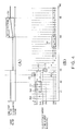
- FIG. 4(A) is a diagram showing an example of a variation of the target voltage.
- Figure 4(B) is a diagram showing an example of a variation of the peak value in each cycle. In Figure 4(B) , open circles are plots of the value of the peak of the inverse of the rotation number.
- Figure 5 is a flowchart showing an example of the power generation controlling method according to the embodiment 1 performed by the drive controlling apparatus 100 shown in Figure 1 .
- a stroke (1) in Figure 4 corresponds to a first step S1 and a second step S2 in Figure 5 .
- a stroke (2) in Figure 4 corresponds to a third step S3 and a fourth step S4 in Figure 5 .
- a stroke (3) in Figure 4 corresponds to a fifth step S5, a sixth step S6, a seventh step S7, an eighth step S8 and a ninth step S9 in Figure 5 .
- a stroke (4) in Figure 4 corresponds to a tenth step S10, an eleventh step S11 and a twelfth step S12 in Figure 5 .
- a stroke (5) in Figure 4 corresponds to a thirteenth step S13, a fourteenth step S14 and a fifteenth step S15 in Figure 5 .
- the drive controlling apparatus 100 judges whether or not the peak of the inverse of the rotation number measured in one cycle of the four-stroke engine 103 is equal to or lower than a first threshold Th1 and equal to or greater than a second threshold Th2, which is lower than the first threshold TH1 (the first step S1).
- the drive controlling apparatus 100 determines whether or not the peak falls within a first judged-to-be-stable range A1.
- the drive controlling apparatus 100 judges in the first step S1 that the peak is not equal to or lower than the first threshold TH1 and equal to or higher than the second threshold TH2, the drive controlling apparatus 100 judges that the rotation of the engine 103 does not fall within the stable range (the first judged-to-be-stable range A1), and judges whether or not the peak of the inverse of the rotation number measured in the next cycle is located between the first threshold TH1 and the second threshold TH2.
- the drive controlling apparatus 100 judges whether or not the peak of the inverse of the rotation number measured in each of the cycle and a plurality of successive cycles following the cycle is equal to or lower than the first threshold TH1 and equal to or higher than the second threshold TH2 (the second step S2).
- the drive controlling apparatus 100 judges whether or not each of the peaks falls within the first judged-to-be-stable range A1. If the state where the throttle is closed continues, the rotation number of the engine 103 is stable at an idling rotation number.
- the drive controlling apparatus 100 judges in the second step S2 that any of the peaks is not equal to or lower than the first threshold TH1 and equal to or higher than the second threshold TH2, the drive controlling apparatus 100 judges that the rotation of the four-stroke engine 103 does not continuously fall within the stable range and returns to the first step S1, in which the drive controlling apparatus 100 judges whether or not the peak of the inverse of the rotation number measured in the next cycle is located between the first threshold TH1 and the second threshold TH2.
- the drive controlling apparatus 100 judges in the second step S2 that each peak is equal to or lower than the first threshold TH1 and equal to or higher than the second threshold TH2, the drive controlling apparatus 100 judges whether or not a first peak of the inverse of the rotation number measured in a first cycle following the plurality of successive cycles is equal to or lower than the second threshold TH2 (the third step S3).
- the drive controlling apparatus 100 judges in the third step S3 that the first peak is equal to or lower than the second threshold TH2, the drive controlling apparatus 100 judges that the amount of the intake air in the intake stroke of the first cycle is low and returns to the first step S1, in which the drive controlling apparatus 100 judges whether or not the peak of the inverse of the rotation number measured in the next cycle is located between the first threshold TH1 and the second threshold TH2.
- the drive controlling apparatus 100 judges whether or not the first peak is equal to or higher than a third threshold TH3, which is higher than the first threshold TH1 (the fourth step S4).
- the drive controlling apparatus 100 judges in the fourth step S4 that the first peak is not equal to or higher than the third threshold TH3, the drive controlling apparatus 100 judges that the rotation of the four-stroke engine 103 is stable and returns to the third step S3.
- the drive controlling apparatus 100 judges that the first peak is equal to or higher than the third threshold TH3
- the drive controlling apparatus 100 starts counting of an acceleration determination period (the fifth step S5). That is, the drive controlling apparatus 100 judges that the amount of the intake air in the intake stroke is large and acceleration is yet to start, and starts counting of the acceleration determination period.
- the drive controlling apparatus 100 judges whether or not the acceleration determination period has elapsed (the sixth step S6).
- the drive controlling apparatus 100 judges in the sixth step S6 that the acceleration determination period has elapsed, the drive controlling apparatus 100 returns to the first step S1, in which the drive controlling apparatus 100 judges whether or not the peak of the inverse of the rotation number measured in the next cycle is located between the first threshold TH1 and the second threshold TH2.
- the drive controlling apparatus 100 judges whether or not a second peak of the inverse of the rotation number measured in a second cycle following the first cycle is equal to or lower than a fourth threshold TH4, which is lower than the second threshold TH2 (the seventh step S7).
- the drive controlling apparatus 100 judges in the seventh step S7 that the second peak is not equal to or lower than the fourth threshold TH4 (that is, no acceleration is occurring), the drive controlling apparatus 100 returns to the sixth step S6, in which the drive controlling apparatus 100 judges again whether or not the acceleration determination period has elapsed.
- the drive controlling apparatus 100 changes the target voltage of the power generation by the generator 102 a rotating shaft of which is connected to the crank shaft of the four-stroke engine 103 from a normal state voltage to an in-acceleration voltage, which is lower than the normal state voltage (the eighth step S8).
- the drive controlling apparatus 100 designates the second peak as a fifth threshold TH5 (the ninth step S9).
- the engine 103 is controlled to output power.
- the load on the engine 103 is desirably abruptly lightened, and therefore, the target voltage can be instantaneously changed from the normal state voltage to the in-acceleration voltage.
- the drive controlling apparatus 100 judges whether or not a third peak of the inverse of the rotation number measured in a third cycle following the second cycle is lower than the fifth threshold TH5 (the tenth step S10).
- the drive controlling apparatus 100 judges whether or not a fourth peak of the inverse of the rotation number measured in a fourth cycle following the third cycle is equal to or lower than a sixth threshold TH6, which is lower than the fifth threshold TH5, and equal to or higher than a seventh threshold TH7, which is lower than the sixth threshold TH6 (that is, whether the fourth peak falls within a second judged-to-be-stable range A2) (the eleventh step S11).
- the drive controlling apparatus 100 judges in the eleventh step S11 that the fourth peak is not equal to or lower than the sixth threshold TH6 and equal to or higher than the seventh threshold TH7, the drive controlling apparatus 100 returns to the tenth step S10, in which the drive controlling apparatus 100 judges whether or not the peak in a cycle following the fourth cycle (the next cycle following the fourth cycle, for example) is equal to or higher than the fifth threshold TH5. In this case, the peak in that following cycle is treated as the third peak described above.
- the drive controlling apparatus 100 judges whether or not each of the peaks of the inverses of the rotation numbers measured in a plurality of successive cycles following the fourth cycle is equal to or lower than the sixth threshold TH7 and equal to or higher than the seventh threshold TH7 (that is, whether the peak falls within the second judged-to-be-stable range A2) (the twelfth step S12).
- the drive controlling apparatus 100 judges in the twelfth step S12 that each peak is not equal to or lower than the sixth threshold TH6 and equal to or higher than the seventh threshold TH7, the drive controlling apparatus 100 returns to the tenth step S10, in which the drive controlling apparatus 100 judges whether or not the peak in a cycle following the plurality of successive cycles following the fourth cycle (the next cycle following the plurality of cycles, for example) is equal to or higher than the fifth threshold TH5. In this case, the peak in that following cycle is treated as the third peak described above.
- the drive controlling apparatus 100 judges in the twelfth step S12 that each peak is equal to or lower than the sixth threshold TH6 and equal to or higher than the seventh threshold TH7, the drive controlling apparatus 100 starts counting of a restoration period (the thirteenth step S13).
- the drive controlling apparatus 100 judges in the tenth step S10 described above that the third peak is equal to or higher than the fifth threshold TH5, the drive controlling apparatus 100 proceeds to the thirteenth step S13, in which the drive controlling apparatus 100 starts counting of the restoration period.
- the drive controlling apparatus 100 After starting counting of the restoration period in the thirteenth step S13, the drive controlling apparatus 100 gradually changes the target voltage from the in-acceleration voltage to the normal state voltage (the fourteenth step S14).
- the drive controlling apparatus 100 judges whether or not the restoration period has elapsed. If the restoration period has elapsed, the drive controlling apparatus 100 stops the change of the target voltage (the fifteenth step S15).
- the drive controlling apparatus 100 judges in the fifteenth step S15 that the restoration period has not elapsed, the drive controlling apparatus 100 returns to the fourteenth step S14, in which the drive controlling apparatus 100 gradually changes the target voltage toward the normal state voltage.
- the engine 103 In the case where the target voltage is to be increased in this way, the engine 103 is trying to make the rotation number stable. Thus, if the load on the engine 103 abruptly increases, the rotation number may drop. Therefore, the target voltage is gradually restored to the normal state voltage, and upon completion of the restoration, the drive controlling apparatus 100 waits for the rotation number to be stable and performs monitoring again.
- the power generation controlling method takes advantage of the phenomenon that, when the operation of the four-stroke engine changes to the acceleration state, the amount of the intake air of the four-stroke engine changes, and the rotation number decreases immediately before the acceleration starts.
- each of the peaks of the inverses of the rotation numbers measured in a plurality of successive cycles of the four-stroke engine is equal to or lower than the first threshold and equal to or higher than the second threshold. If the first peak of the inverse of the rotation number measured in the first cycle following the plurality of successive cycles is not equal to or lower than the second threshold, it is judged whether or not the first peak is equal to or higher than the third threshold, which is higher than the first threshold.
- the target voltage of the power generation by the generator, the rotating shaft of which is connected to the crank shaft of the four-stroke engine is changed from the normal state voltage to the in-acceleration voltage, which is lower than the normal state voltage.
- the power generation controlling method according to this embodiment can reduce the manufacturing cost of a motorcycle.
- the power generation controlling method according to the embodiment 2 is performed by the drive controlling apparatus 100 of the drive controlling system 1000 shown in Figure 1 , as with the power generation controlling method according to the embodiment 1.
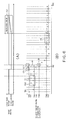
- Figure 6(A) is a diagram showing an example of a variation of the target voltage.
- Figure 6(B) is a diagram showing an example of a variation of the peak value in each cycle.
- open circles are plots of the value of the peak of the inverse of the rotation number.
- Figure 7 is a flowchart showing an example of the power generation controlling method according to the embodiment 2 performed by the drive controlling apparatus 100 shown in Figure 1 .
- the same reference numerals as those in Figure 5 denote the same steps as those in Figs 5 .
- a stroke (1) in Figure 6 corresponds to the first step S1 and the second step S2 in Figure 7 .
- a stroke (2) in Figure 6 corresponds to the third step S3, the fourth step S4 and a fifth step S205 in Figure 5 .
- Strokes (3) and (3') in Figure 6 correspond to a sixth step S206, a seventh step S207, an eighth step S208, a ninth step S209 and a tenth step S210 in Figure 7 .
- a stroke (4) in Figure 6 corresponds to an eleventh step S211, a twelfth step S212 and a thirteenth step S213 in Figure 7 .
- a stroke (5) in Figure 6 corresponds to a fourteenth step S214, a fifteenth step S215 and a sixteenth step S216 in Figure 7 .
- the drive controlling apparatus 100 performs the first step S1, the second step S2, the third step S3 and the fourth step S4.
- the drive controlling apparatus 100 judges in the fourth step S4 that the first peak is equal to or higher than the third threshold TH3, the drive controlling apparatus 100 changes the target voltage from the normal state voltage to the in-acceleration voltage (the fifth step S205).
- the drive controlling apparatus 100 After changing the target voltage from the normal state voltage to the in-acceleration voltage, the drive controlling apparatus 100 starts counting of the acceleration determination period (the sixth step S206).
- the drive controlling apparatus 100 judges whether or not the second peak of the inverse of the rotation number measured in the second cycle following the first cycle is equal to or higher than the third threshold TH3 (the seventh step S207).
- the drive controlling apparatus 100 judges whether or not the acceleration determination period has elapsed (the eighth step S208).
- the drive controlling apparatus 100 judges in the eighth step S208 that the acceleration determination period has not elapsed, the drive controlling apparatus 100 returns to the seventh step S207, in which the drive controlling apparatus 100 judges whether or not the second peak of the inverse of the rotation number measured in the next cycle is equal to or higher than the third threshold TH3.
- the drive controlling apparatus 100 judges in the eighth step S208 that the acceleration determination period has elapsed, the drive controlling apparatus 100 changes the target voltage from the in-acceleration voltage to the normal state voltage (the ninth step S209).
- the drive controlling apparatus 100 judges in the seventh step S207 described above that the second peak is not equal to or higher than the third threshold TH3, the drive controlling apparatus 100 judges whether or not the second peak is equal to or lower than the fourth threshold TH4 (the tenth step S210).
- the drive controlling apparatus 100 judges in the tenth step S210 that the second peak is not equal to or lower than the fourth threshold TH4, the drive controlling apparatus 100 returns to the seventh step S207, in which the drive controlling apparatus 100 judges whether or not the third peak of the inverse of the rotation number measured in the third cycle following the second cycle is equal to or higher than the third threshold TH3.
- the drive controlling apparatus 100 judges whether or not the third peak of the inverse of the rotation number measured in the third cycle following the second cycle is lower than the fifth threshold TH5 (the eleventh step S211).
- the drive controlling apparatus 100 judges whether or not the fourth peak of the inverse of the rotation number measured in the fourth cycle following the third cycle is equal to or lower than the sixth threshold TH6, which is lower than the fifth threshold TH5, and equal to or higher than the seventh threshold TH7, which is lower than the sixth threshold TH6 (that is, whether the fourth peak falls within the second judged-to-be-stable range A2) (the twelfth step S212).
- the drive controlling apparatus 100 judges in the twelfth step S212 that the fourth peak is not equal to or lower than the sixth threshold TH6 and equal to or higher than the seventh threshold TH7, the drive controlling apparatus 100 returns to the eleventh step S211, in which the drive controlling apparatus 100 judges whether or not the peak in a cycle following the fourth cycle (the next cycle following the fourth cycle, for example) is equal to or higher than the fifth threshold TH5. In this case, the peak in that following cycle is treated as the third peak described above.
- the drive controlling apparatus 100 judges whether or not each peak of the inverses of the rotation numbers measured in a plurality of successive cycles following the fourth cycle is equal to or lower than the sixth threshold TH6 and equal to or higher than the seventh threshold TH7 (that is, whether the peak falls within the second judged-to-be-stable range A2) (the thirteenth step S213).
- the drive controlling apparatus 100 judges in the thirteenth step S213 that each peak is not equal to or lower than the sixth threshold TH6 and equal to or higher than the seventh threshold TH7, the drive controlling apparatus 100 returns to the eleventh step S211, in which the drive controlling apparatus 100 judges whether or not the peak in a cycle following the plurality of successive cycles following the fourth cycle (the next cycle following the plurality of cycles, for example) is equal to or higher than the fifth threshold TH5. In this case, the peak in that following cycle is treated as the third peak described above.
- the drive controlling apparatus 100 judges in the thirteenth step S213 that each peak is equal to or lower than the sixth threshold TH6 and equal to or higher than the seventh threshold TH7, the drive controlling apparatus 100 starts counting of the restoration period (the fourteenth step S214).
- the drive controlling apparatus 100 judges in the eleventh step S211 described above that the third peak is equal to or higher than the fifth threshold TH5, the drive controlling apparatus 100 proceeds to the fourteenth step S214, in which the drive controlling apparatus 100 starts counting of the restoration period.
- the drive controlling apparatus 100 After starting counting of the restoration period in the fourteenth step S214, the drive controlling apparatus 100 gradually changes the target voltage from the in-acceleration voltage to the normal state voltage (the fifteenth step S215).
- the drive controlling apparatus 100 judges whether or not the restoration period has elapsed. If the restoration period has elapsed, the drive controlling apparatus 100 stops the change of the target voltage (the sixteenth step S216).
- the drive controlling apparatus 100 judges in the sixteenth step S216 that the restoration period has not elapsed, the drive controlling apparatus 100 returns to the fifteenth step S215, in which the drive controlling apparatus 100 gradually changes the target voltage toward the normal state voltage.
- the engine 103 In the case where the target voltage is to be increased in this way, the engine 103 is trying to make the rotation number stable. Thus, if the load on the engine 103 abruptly increases, the rotation number may drop. Therefore, the target voltage is gradually restored to the normal state voltage, and upon completion of the restoration, the drive controlling apparatus 100 waits for the rotation number to be stable and performs monitoring again.
- the power generation controlling method takes advantage of the phenomenon that, when the operation of the four-stroke engine changes to the acceleration state, the amount of the intake air of the four-stroke engine changes, and the rotation number decreases immediately before the acceleration starts.
- the acceleration state can be judged and the target voltage can be changed based on the information on the rotation number of the four-stroke engine without using the information on the operation of the throttle.
- the power generation controlling method according to this embodiment can reduce the manufacturing cost of a motorcycle.
- Figure 1 shows the engine 103 and the motor 102 integrated with each other, the engine 103 and the motor 102 can be separate units.
- the embodiments show cases where the motor 102 functions as both a electric motor and a generator.
- the drive controlling apparatus 100 can modify the first threshold TH1 and the second threshold TH2.
- the drive controlling apparatus 100 performs the power generation controlling methods described above using the set first threshold TH1 and second threshold TH2.
- the first judged-to-be-stable range A1 can be set depending on the required operating conditions of the engine or the like.
- the drive controlling apparatus 100 can modify the sixth threshold TH6 and the seventh threshold TH7 depending on the required operating conditions of the engine.
- the drive controlling apparatus 100 performs the power generation controlling methods described above using the set sixth threshold TH6 and seventh threshold TH7.
- the second judged-to-be-stable range A2 can be set depending on the required operating conditions of the engine or the like.
Landscapes
- Engineering & Computer Science (AREA)
- Chemical & Material Sciences (AREA)
- Combustion & Propulsion (AREA)
- Mechanical Engineering (AREA)
- General Engineering & Computer Science (AREA)
- Power Engineering (AREA)
- Control Of Eletrric Generators (AREA)
- Control Of Vehicle Engines Or Engines For Specific Uses (AREA)
- Combined Controls Of Internal Combustion Engines (AREA)
Abstract
Description
- The present invention relates to a drive controlling apparatus and a power generation controlling method.
- There is a conventional technique of reducing a target voltage based on information on the operation of a throttle, for example, in order to reduce the load on the engine of a motorcycle during acceleration (see J270445B, for example). As the target voltage decreases, the amount of the electric power generated by a motor (generator) connected to the engine (i.e., the amount of the electricity with which a battery is charged) decreases, and therefore, the load on the engine decreases. Thus, the acceleration performance of the engine can be prevented from deteriorating.
- For example, a user operates the throttle to accelerate the engine. According to the conventional technique described above, the time for the engine to accelerate is recognized based on the amount of the movement of the throttle caused by the operation, and the target voltage is changed according to the recognized time.
- According to the conventional technique described above, the time to accelerate is recognized based on the amount of the movement of the throttle. Therefore, there is a problem that an additional sensor that detects the amount of the movement of the throttle is needed, and therefore the manufacturing cost of the motorcycle increases.
- A power generation controlling method according to an embodiment being one aspect of the present invention is a power generation controlling method of controlling a generator connected to a four-stroke engine based on a result of measurement of an inverse of an rotation number of the four-stroke engine, comprising:
- a first step of judging whether or not a peak of the inverse of the rotation number measured in a cycle of the four-stroke engine is equal to or lower than a first threshold and equal to or higher than a second threshold, the second threshold being lower than the first threshold;
- a second step of, in a case where the peak is equal to or lower than the first threshold and equal to or higher than the second threshold, judging whether or not each of peaks of the inverses of the rotation numbers measured in a plurality of successive cycles following the cycle is equal to or lower than the first threshold and equal to or higher than the second threshold;
- a third step of, in a case where it is judged in the second step that each of the peaks is equal to or lower than the first threshold and equal to or higher than the second threshold, judging whether or not a first peak of the inverse of the rotation number measured in a first cycle following the plurality of successive cycles is equal to or lower than the second threshold;
- a fourth step of, in a case where the first peak is not equal to or lower than the second threshold, judging whether or not the first peak is equal to or higher than a third threshold, the third threshold being higher than the first threshold;
- a fifth step of starting counting of an acceleration determination period after judging that the first peak is equal to or higher than the third threshold;
- a sixth step of judging whether or not the acceleration determination period has elapsed;
- a seventh step of, in a case where the acceleration determination period has not elapsed, judging whether or not a second peak of the inverse of the rotation number measured in a second cycle following the first cycle is equal to or lower than a fourth threshold, the fourth threshold being lower than the second threshold;
- an eighth step of, in a case where the second peak is equal to or lower than the fourth threshold, changing a target voltage of power generation by the generator a rotating shaft of which is connected to a crank shaft of the four-stroke engine from a normal state voltage to an in-acceleration voltage, the in-acceleration voltage being lower than the normal state voltage; and
- a ninth step of, in a case where the second peak is equal to or lower than the fourth threshold, designating the second peak as a fifth threshold.
- In the power generation controlling method, the power generation controlling method may further comprise:
- a tenth step of, after changing the target voltage from the normal state voltage to the in-acceleration voltage, judging whether or not a third peak of the inverse of the rotation number measured in a third cycle following the second cycle is lower than the fifth threshold;
- an eleventh step of, in a case where the third peak is not equal to or higher than the fifth threshold, judging whether or not a fourth peak of the inverse of the rotation number measured in a fourth cycle following the third cycle is equal to or lower than a sixth threshold and equal to or higher than a seventh threshold, the sixth threshold being lower than the fifth threshold, and the seventh threshold being lower than the sixth threshold;
- a twelfth step of, in a case where the fourth peak is equal to or lower than the sixth threshold and equal to or higher than the seventh threshold, judging whether or not each of peaks of the inverses of the rotation numbers measured in a plurality of successive cycles following the fourth cycle is equal to or lower than the sixth threshold and equal to or higher than the seventh threshold;
- a thirteenth step of starts counting of a restoration period after it is judged in the twelfth step that each of the peaks is equal to or lower than the sixth threshold and equal to or higher than the seventh threshold;
- a fourteenth step of gradually changing the target voltage from the in-acceleration voltage to the normal state voltage after starting counting of the restoration period; and
- a fifteenth step of judging whether or not the restoration period has elapsed and stopping the change of the target voltage in a case where the restoration period has elapsed.
- In the power generation controlling method, in a case where it is judged in the first step that the peak is not equal to or lower than the first threshold and equal to or higher than the second threshold, it may be judged whether or not a peak of the inverse of the rotation number measured in a next cycle is located between the first threshold and the second threshold.
- In the power generation controlling method, in a case where it is judged in the second step that any of the peaks is not equal to or lower than the first threshold and equal to or higher than the second threshold, the method returns to the first step, and it may be judged whether or not a peak of the inverse of the rotation number measured in a next cycle is located between the first threshold and the second threshold.
- In the power generation controlling method, in a case where it may be judged in the third step that the first peak is equal to or lower than the second threshold, the method returns to the first step, and it is judged whether or not a peak of the inverse of the rotation number measured in a next cycle is located between the first threshold and the second threshold.
- In the power generation controlling method, in a case where it may be judged in the fourth step that the first peak is not equal to or higher than the third threshold, the method returns to the third step.
- In the power generation controlling method, in a case where it may be judged in the sixth step that the acceleration determination period has elapsed, the method returns to the first step, and it is judged whether or not a peak of the inverse of the rotation number measured in a next cycle is located between the first threshold and the second threshold.
- In the power generation controlling method, in a case where it may be judged in the seventh step that the second peak is not equal to or lower than the fourth threshold, the method returns to the sixth step, and it is judged again whether or not the acceleration determination period has elapsed.
- In the power generation controlling method, in a case where it may be judged in the tenth step that the third peak is equal to or higher than the fifth threshold, the method proceeds to the thirteenth step and starts counting of the restoration period.
- In the power generation controlling method, in a case where it may be judged in the eleventh step that the fourth peak is not equal to or lower than the sixth threshold and equal to or higher than the seventh threshold, the method returns to the tenth step, and it is judged whether or not a peak in a cycle following the fourth cycle is equal to or higher than the fifth threshold.
- In the power generation controlling method, in a case where it may be judged in the twelfth step that each of the peaks is not equal to or lower than the sixth threshold and equal to or higher than the seventh threshold, the method returns to the tenth step, and it is judged whether or not a peak in a cycle following the plurality of successive cycles following the fourth cycle is equal to or higher than the fifth threshold.
- In the power generation controlling method, in a case where it may be judged in the fifteenth step that the restoration period has not elapsed, the method returns to the fourteenth step, and the target voltage is gradually changed toward the normal state voltage.
- A power generation controlling method according to an embodiment being one aspect of the present invention is a power generation controlling method of controlling a generator connected to a four-stroke engine based on a result of measurement of an inverse of an rotation number of the four-stroke engine, comprises:
- a first step of judging whether or not a peak of the inverse of the rotation number measured in a cycle of the four-stroke engine is equal to or lower than a first threshold and equal to or higher than a second threshold, the second threshold being lower than the first threshold;
- a second step of, in a case where the peak is equal to or lower than the first threshold and equal to or higher than the second threshold, judging whether or not each of peaks of the inverses of the rotation numbers measured in a plurality of successive cycles following the cycle is equal to or lower than the first threshold and equal to or higher than the second threshold;
- a third step of, in a case where it is judged in the second step that each of the peaks is equal to or lower than the first threshold and equal to or higher than the second threshold, judging whether or not a first peak of the inverse of the rotation number measured in a first cycle following the plurality of successive cycles is equal to or lower than the second threshold;
- a fourth step of, in a case where the first peak is not equal to or lower than the second threshold, judging whether or not the first peak is equal to or higher than a third threshold, the third threshold being higher than the first threshold;
- a fifth step of, in a case where the first peak is equal to or higher than the third threshold, changing a target voltage of power generation by a motor a rotating shaft of which is connected to a crank shaft of the four-stroke engine from a normal state voltage to an in-acceleration voltage, the in-acceleration voltage being lower than the normal state voltage.
- In the power generation controlling method, the power generation controlling method may further comprise:
- a sixth step of starting counting of an acceleration determination period after changing the target voltage from the normal state voltage to the in-acceleration voltage;
- a seventh step of judging whether or not a second peak of the inverse of the rotation number measured in a second cycle following the first cycle is equal to or higher than the third threshold;
- an eighth step of, in a case where the second peak is equal to or higher than the third threshold, judging whether or not the acceleration determination period has elapsed; and
- a ninth step of, in a case where it is judged in the eighth step that the acceleration determination period has elapsed, changing the target voltage from the in-acceleration voltage to the normal state voltage.
- In the power generation controlling method, in a case where it may be judged in the eighth step that the acceleration determination period has not elapsed, the method returns to the seventh step, and it is judged whether or not the second peak of the inverse of the rotation number measured in a next cycle is equal to or higher than the third threshold.
- In the power generation controlling method, the power generation controlling method may further comprise:
- a tenth step of, in a case where it is judged in the seventh step that the second peak is not equal to or higher than the third threshold, judging whether or not the second peak is equal to or lower than the fourth threshold.
- In the power generation controlling method, in a case where it may be judged in the tenth step that the second peak is not equal to or lower than the fourth threshold, the method returns to the seventh step, and it is judged whether or not a third peak of the inverse of the rotation number measured in a third cycle following the second cycle is equal to or higher than the third threshold.
- In the power generation controlling method, the peak of the inverse of the rotation number is measured in a compression stroke of a cycle of the four-stroke engine.
- A drive controlling apparatus according to an embodiment being one aspect of the invention is a drive controlling apparatus that controls driving of a four-stroke engine, performs:
- a first step of judging whether or not a peak of an inverse of an rotation number measured in a cycle of the four-stroke engine is equal to or lower than a first threshold and equal to or higher than a second threshold, the second threshold being lower than the first threshold;
- a second step of, in a case where the peak is equal to or lower than the first threshold and equal to or higher than the second threshold, judging whether or not each of peaks of the inverses of the rotation numbers measured in a plurality of successive cycles following the cycle is equal to or lower than the first threshold and equal to or higher than the second threshold;
- a third step of, in a case where it is judged in the second step that each of the peaks is equal to or lower than the first threshold and equal to or higher than the second threshold, judging whether or not a first peak of the inverse of the rotation number measured in a first cycle following the plurality of successive cycles is equal to or lower than the second threshold;
- a fourth step of, in a case where the first peak is not equal to or lower than the second threshold, judging whether or not the first peak is equal to or higher than a third threshold, the third threshold being higher than the first threshold;
- a fifth step of starting counting of an acceleration determination period after judging that the first peak is equal to or higher than the third threshold;
- a sixth step of judging whether or not the acceleration determination period has elapsed;
- a seventh step of, in a case where the acceleration determination period has not elapsed, judging whether or not a second peak of the inverse of the rotation number measured in a second cycle following the first cycle is equal to or lower than a fourth threshold, the fourth threshold being lower than the second threshold;
- an eighth step of, in a case where the second peak is equal to or lower than the fourth threshold, changing a target voltage of power generation by the generator a rotating shaft of which is connected to a crank shaft of the four-stroke engine from a normal state voltage to an in-acceleration voltage, the in-acceleration voltage being lower than the normal state voltage; and
- a ninth step of, in a case where the second peak is equal to or lower than the fourth threshold, designating the second peak as a fifth threshold.
- In the drive controlling apparatus, the drive controlling apparatus may further perform:
- a tenth step of, after changing the target voltage from the normal state voltage to the in-acceleration voltage, judging whether or not a third peak of the inverse of the rotation number measured in a third cycle following the second cycle is lower than the fifth threshold;
- an eleventh step of, in a case where the third peak is not equal to or higher than the fifth threshold, judging whether or not a fourth peak of the inverse of the rotation number measured in a fourth cycle following the third cycle is equal to or lower than a sixth threshold and equal to or higher than a seventh threshold, the sixth threshold being lower than the fifth threshold, and the seventh threshold being lower than the sixth threshold;
- a twelfth step of, in a case where the fourth peak is equal to or lower than the sixth threshold and equal to or higher than the seventh threshold, judging whether or not each of peaks of the inverses of the rotation numbers measured in a plurality of successive cycles following the fourth cycle is equal to or lower than the sixth threshold and equal to or higher than the seventh threshold;
- a thirteenth step of starts counting of a restoration period after it is judged in the twelfth step that each of the peaks is equal to or lower than the sixth threshold and equal to or higher than the seventh threshold;
- a fourteenth step of gradually changing the target voltage from the in-acceleration voltage to the normal state voltage after starting counting of the restoration period; and
- a fifteenth step of judging whether or not the restoration period has elapsed and stopping the change of the target voltage in a case where the restoration period has elapsed.
- In the drive controlling apparatus, the drive controlling apparatus can modify the first threshold and the second threshold.
- In the drive controlling apparatus, the drive controlling apparatus can modify the sixth threshold and the seventh threshold.
- A power generation controlling method according to an aspect of the present invention takes advantage of the phenomenon that, when the operation of a four-stroke engine changes to an acceleration state, the amount of the intake air of the four-stroke engine changes, and the rotation number decreases immediately before the acceleration starts.
- Specifically, it is judged whether or not each of the peaks of the inverses of the rotation numbers measured in a plurality of successive cycles of the four-stroke engine is equal to or lower than a first threshold and equal to or higher than a second threshold. If a first peak of the inverse of the rotation number measured in a first cycle following the plurality of successive cycles described above is not equal to or lower than the second threshold, it is judged whether or not the first peak is equal to or higher than a third threshold, which is higher than the first threshold.
- In this way, it is possible to detect a decrease of the rotation number of the engine caused by an increase of the amount of the intake air of the four-stroke engine in acceleration.
- Furthermore, if a second peak of the inverse of the rotation number measured in a second cycle following the first cycle is equal to or lower than a fourth threshold, a target voltage of power generation by a generator a rotating shaft of which is connected to a crank shaft of the four-stroke engine is changed from a normal state voltage to an in-acceleration voltage, which is lower than the normal state voltage.
- In this way, it is possible to change the target voltage by judging the acceleration state based on information on the rotation number of the four-stroke engine without using information on the operation of a throttle.
- That is, the power generation controlling method according to this aspect of the present invention can reduce the manufacturing cost of a motorcycle.
-
- [
FIG. 1] Figure 1 is a diagram showing an example of a configuration of adrive controlling system 1000 according to anembodiment 1, which is an aspect of the present invention. - [
FIG. 2] Figure 2 is a diagram showing an example of a relationship between each stroke (a crank angle) in one cycle of anengine 103 of thedrive controlling system 1000 shown inFigure 1 and the pressure in a cylinder. - [
FIG. 3] Figure 3 is a diagram showing an example of a relationship between the inverse of the rotation number of the four-stroke engine 103 and time. - [
FIG. 4] Figure 4(A) is a diagram showing an example of a variation of the target voltage.Figure 4(B) is a diagram showing an example of a variation of the peak value in each cycle. - [
FIG. 5] Figure 5 is a flowchart showing an example of the power generation controlling method according to theembodiment 1 performed by thedrive controlling apparatus 100 shown inFigure 1 . - [
FIG. 6] Figure 6(A) is a diagram showing an example of a variation of the target voltage.Figure 6(B) is a diagram showing an example of a variation of the peak value in each cycle. - [
FIG. 7] Figure 7 is a flowchart showing an example of the power generation controlling method according to theembodiment 2 performed by thedrive controlling apparatus 100 shown inFigure 1 . - In the following, embodiments of the present invention will be described with reference to the drawings.
-
Figure 1 is a diagram showing an example of a configuration of adrive controlling system 1000 according to anembodiment 1, which is an aspect of the present invention.Figure 2 is a diagram showing an example of a relationship between each stroke (a crank angle) in one cycle of anengine 103 of thedrive controlling system 1000 shown inFigure 1 and the pressure in a cylinder. - As shown in
Figure 1 , thedrive controlling system 1000 that controls driving of the engine includes a drive controlling apparatus (an engine control unit (ECU)) 100, abattery 101, amotor 102, an engine (an internal combustion engine) 103 and asensor 104. - The
engine 103 is a four-stroke engine (sometimes expressed as a four-stroke engine 103 as required hereinafter). Therefore, as shown inFigure 2 , the state of theengine 103 transitions through an intake stroke, a compression stroke, a combustion stroke and an exhaust stroke. In addition, as shown inFigure 2 , the pressure in the cylinder of the engine 103 (that is, the resistance to the rotation of the crank) reaches a maximum at a top dead center. - The
motor 102 is configured to apply a torque to a crank shaft of theengine 103. In this example, themotor 102 is coupled to the crank shaft of theengine 103 in such a manner that themotor 102 can apply a torque to and receive a torque from the crank shaft. That is, themotor 102 is connected to theengine 103 and functions as both a electric motor and a generator (themotor 102 will be sometimes expressed as agenerator 102 as required hereinafter). - The
sensor 104 is configured to detect the rotation number and the crank angle of theengine 103 and output a detection signal responsive to the result of the detection. - The
battery 101 is configured to supply a driving electric power to themotor 102 or be charged with an electric power regenerated by themotor 102. - The
drive controlling apparatus 100 is configured to control driving of theengine 103 by judging the state of theengine 103 based on the detection signal (that is, the rotation number and the crank angle of theengine 103 obtained from the detection signal). In particular, if there is a restart request for theengine 103, thedrive controlling apparatus 100 drives themotor 102 to control the operation of theengine 103. - The
drive controlling apparatus 100 has a central processing unit (CPU) 100a, a read only memory (ROM) 100b and an electricpower controlling circuit 100c, for example. - The electric
power controlling circuit 100c is configured to control the operation of themotor 102 that applies a torque to theengine 103. - The
ROM 100b is configured to store a map for controlling start or other operation of the engine 103 (i.e., for controlling the motor 102). - The
CPU 100a is configured to refer to theROM 100c and control the electricpower controlling circuit 100c to control themotor 102 based on the rotation number and the crank angle of theengine 103 detected by thesensor 101. -
Figure 3 is a diagram showing an example of a relationship between the inverse of the rotation number of the four-stroke engine 103 and time. The inverse of the rotation number of the four-stroke engine 103 is the duration of each stroke of the four-stroke engine 103, for example, the time between adjacent angles detected by an angle sensor including a Hall IC. - As shown in
Figure 3 , a peak of the inverse of the rotation number appears in the compression stroke of each cycle (shown by a circle inFigure 3 ). - In particular, the peak of the inverse of the rotation number that appears in the vicinity of a time "X" in
Figure 3 is higher than the other peaks. In the vicinity of the time "X," an operation to open the throttle occurs. If the operation to open the throttle occurs, the amount of the air flowing into the engine cylinder increases, and the pressure in compression increases. That is, in the vicinity of the time "X" in which the throttle is opened, the operation of the four-stroke engine changes into an acceleration state, and the amount of the intake air of the four-stroke engine changes. As a result, the rotation number decreases (the peak of the inverse of the rotation number becomes higher than a predetermined value) immediately before the acceleration starts. - The time at which the peak of the inverse of the rotation number becomes higher than the predetermined value is judged as a state where the user opens the throttle to achieve acceleration. Based on the judgment, the time to reduce the load on the engine is set. In this way, the acceleration state can be judged and the target voltage can be changed based on the information on the rotation number of the four-stroke engine without using the information on the operation of the throttle.
- It is to be noted that the
drive controlling apparatus 100 measures the peak of the inverse of the rotation number in the compression stroke of a cycle of the four-stroke engine 103. That is, the peak of the inverse of the rotation number corresponds to the vicinity of the top dead center of the compression stroke. - Next, provided the phenomenon described above, an example of a power generation controlling method performed by the
drive controlling apparatus 100 of thedrive controlling system 1000 configured as described above will be described. The power generation controlling method performed by thedrive controlling apparatus 100 is to control thegenerator 102 connected to the four-stroke engine 103 based on the result of the measurement of the inverse of the rotation number of the four-stroke engine 103.
Figure 4(A) is a diagram showing an example of a variation of the target voltage.Figure 4(B) is a diagram showing an example of a variation of the peak value in each cycle. InFigure 4(B) , open circles are plots of the value of the peak of the inverse of the rotation number.Figure 5 is a flowchart showing an example of the power generation controlling method according to theembodiment 1 performed by thedrive controlling apparatus 100 shown inFigure 1 . A stroke (1) inFigure 4 corresponds to a first step S1 and a second step S2 inFigure 5 . A stroke (2) inFigure 4 corresponds to a third step S3 and a fourth step S4 inFigure 5 . A stroke (3) inFigure 4 corresponds to a fifth step S5, a sixth step S6, a seventh step S7, an eighth step S8 and a ninth step S9 inFigure 5 . A stroke (4) inFigure 4 corresponds to a tenth step S10, an eleventh step S11 and a twelfth step S12 inFigure 5 . A stroke (5) inFigure 4 corresponds to a thirteenth step S13, a fourteenth step S14 and a fifteenth step S15 inFigure 5 . - As shown in
Figure 5 , first, thedrive controlling apparatus 100 judges whether or not the peak of the inverse of the rotation number measured in one cycle of the four-stroke engine 103 is equal to or lower than a first threshold Th1 and equal to or greater than a second threshold Th2, which is lower than the first threshold TH1 (the first step S1). - In other words, the
drive controlling apparatus 100 determines whether or not the peak falls within a first judged-to-be-stable range A1. - If the
drive controlling apparatus 100 judges in the first step S1 that the peak is not equal to or lower than the first threshold TH1 and equal to or higher than the second threshold TH2, thedrive controlling apparatus 100 judges that the rotation of theengine 103 does not fall within the stable range (the first judged-to-be-stable range A1), and judges whether or not the peak of the inverse of the rotation number measured in the next cycle is located between the first threshold TH1 and the second threshold TH2. - On the other hand, if the peak is equal to or lower than the first threshold TH1 and equal to or higher than the second threshold TH2, the
drive controlling apparatus 100 judges whether or not the peak of the inverse of the rotation number measured in each of the cycle and a plurality of successive cycles following the cycle is equal to or lower than the first threshold TH1 and equal to or higher than the second threshold TH2 (the second step S2). - That is, the
drive controlling apparatus 100 judges whether or not each of the peaks falls within the first judged-to-be-stable range A1. If the state where the throttle is closed continues, the rotation number of theengine 103 is stable at an idling rotation number. - If the
drive controlling apparatus 100 judges in the second step S2 that any of the peaks is not equal to or lower than the first threshold TH1 and equal to or higher than the second threshold TH2, thedrive controlling apparatus 100 judges that the rotation of the four-stroke engine 103 does not continuously fall within the stable range and returns to the first step S1, in which thedrive controlling apparatus 100 judges whether or not the peak of the inverse of the rotation number measured in the next cycle is located between the first threshold TH1 and the second threshold TH2. - On the other hand, if the
drive controlling apparatus 100 judges in the second step S2 that each peak is equal to or lower than the first threshold TH1 and equal to or higher than the second threshold TH2, thedrive controlling apparatus 100 judges whether or not a first peak of the inverse of the rotation number measured in a first cycle following the plurality of successive cycles is equal to or lower than the second threshold TH2 (the third step S3). - On the other hand, if the
drive controlling apparatus 100 judges in the third step S3 that the first peak is equal to or lower than the second threshold TH2, thedrive controlling apparatus 100 judges that the amount of the intake air in the intake stroke of the first cycle is low and returns to the first step S1, in which thedrive controlling apparatus 100 judges whether or not the peak of the inverse of the rotation number measured in the next cycle is located between the first threshold TH1 and the second threshold TH2. - If the first peak is not equal to or lower than the second threshold TH2, the
drive controlling apparatus 100 judges whether or not the first peak is equal to or higher than a third threshold TH3, which is higher than the first threshold TH1 (the fourth step S4). - If the
drive controlling apparatus 100 judges in the fourth step S4 that the first peak is not equal to or higher than the third threshold TH3, thedrive controlling apparatus 100 judges that the rotation of the four-stroke engine 103 is stable and returns to the third step S3. - On the other hand, when the
drive controlling apparatus 100 judges that the first peak is equal to or higher than the third threshold TH3, thedrive controlling apparatus 100 starts counting of an acceleration determination period (the fifth step S5). That is, thedrive controlling apparatus 100 judges that the amount of the intake air in the intake stroke is large and acceleration is yet to start, and starts counting of the acceleration determination period. - Then, the
drive controlling apparatus 100 judges whether or not the acceleration determination period has elapsed (the sixth step S6). - If the
drive controlling apparatus 100 judges in the sixth step S6 that the acceleration determination period has elapsed, thedrive controlling apparatus 100 returns to the first step S1, in which thedrive controlling apparatus 100 judges whether or not the peak of the inverse of the rotation number measured in the next cycle is located between the first threshold TH1 and the second threshold TH2. - On the other hand, if the acceleration determination period has not elapsed (that is, during the acceleration determination period), the
drive controlling apparatus 100 judges whether or not a second peak of the inverse of the rotation number measured in a second cycle following the first cycle is equal to or lower than a fourth threshold TH4, which is lower than the second threshold TH2 (the seventh step S7). - If the
drive controlling apparatus 100 judges in the seventh step S7 that the second peak is not equal to or lower than the fourth threshold TH4 (that is, no acceleration is occurring), thedrive controlling apparatus 100 returns to the sixth step S6, in which thedrive controlling apparatus 100 judges again whether or not the acceleration determination period has elapsed. - On the other hand, if the second peak is equal to or lower than the fourth threshold TH4 (acceleration is occurring), the
drive controlling apparatus 100 changes the target voltage of the power generation by the generator 102 a rotating shaft of which is connected to the crank shaft of the four-stroke engine 103 from a normal state voltage to an in-acceleration voltage, which is lower than the normal state voltage (the eighth step S8). - Furthermore, if the second peak is equal to or lower than the fourth threshold TH4, the
drive controlling apparatus 100 designates the second peak as a fifth threshold TH5 (the ninth step S9). - It is to be noted that, in the case where the target voltage is to be reduced in this way, the
engine 103 is controlled to output power. Thus, the load on theengine 103 is desirably abruptly lightened, and therefore, the target voltage can be instantaneously changed from the normal state voltage to the in-acceleration voltage. - Then, after changing the target voltage from the normal state voltage to the in-acceleration voltage, the
drive controlling apparatus 100 judges whether or not a third peak of the inverse of the rotation number measured in a third cycle following the second cycle is lower than the fifth threshold TH5 (the tenth step S10). - Then, if the third peak is not equal to or higher than the fifth threshold TH5 (that is, acceleration is occurring), the
drive controlling apparatus 100 judges whether or not a fourth peak of the inverse of the rotation number measured in a fourth cycle following the third cycle is equal to or lower than a sixth threshold TH6, which is lower than the fifth threshold TH5, and equal to or higher than a seventh threshold TH7, which is lower than the sixth threshold TH6 (that is, whether the fourth peak falls within a second judged-to-be-stable range A2) (the eleventh step S11). - If the
drive controlling apparatus 100 judges in the eleventh step S11 that the fourth peak is not equal to or lower than the sixth threshold TH6 and equal to or higher than the seventh threshold TH7, thedrive controlling apparatus 100 returns to the tenth step S10, in which thedrive controlling apparatus 100 judges whether or not the peak in a cycle following the fourth cycle (the next cycle following the fourth cycle, for example) is equal to or higher than the fifth threshold TH5. In this case, the peak in that following cycle is treated as the third peak described above. - On the other hand, if the fourth peak is equal to or lower than the sixth threshold TH6 and equal to or higher than the seventh threshold TH7, the
drive controlling apparatus 100 judges whether or not each of the peaks of the inverses of the rotation numbers measured in a plurality of successive cycles following the fourth cycle is equal to or lower than the sixth threshold TH7 and equal to or higher than the seventh threshold TH7 (that is, whether the peak falls within the second judged-to-be-stable range A2) (the twelfth step S12). - If the
drive controlling apparatus 100 judges in the twelfth step S12 that each peak is not equal to or lower than the sixth threshold TH6 and equal to or higher than the seventh threshold TH7, thedrive controlling apparatus 100 returns to the tenth step S10, in which thedrive controlling apparatus 100 judges whether or not the peak in a cycle following the plurality of successive cycles following the fourth cycle (the next cycle following the plurality of cycles, for example) is equal to or higher than the fifth threshold TH5. In this case, the peak in that following cycle is treated as the third peak described above. - When the
drive controlling apparatus 100 judges in the twelfth step S12 that each peak is equal to or lower than the sixth threshold TH6 and equal to or higher than the seventh threshold TH7, thedrive controlling apparatus 100 starts counting of a restoration period (the thirteenth step S13). - It is to be noted that, if the
drive controlling apparatus 100 judges in the tenth step S10 described above that the third peak is equal to or higher than the fifth threshold TH5, thedrive controlling apparatus 100 proceeds to the thirteenth step S13, in which thedrive controlling apparatus 100 starts counting of the restoration period. - After starting counting of the restoration period in the thirteenth step S13, the
drive controlling apparatus 100 gradually changes the target voltage from the in-acceleration voltage to the normal state voltage (the fourteenth step S14). - Then, the
drive controlling apparatus 100 judges whether or not the restoration period has elapsed. If the restoration period has elapsed, thedrive controlling apparatus 100 stops the change of the target voltage (the fifteenth step S15). - On the other hand, if the
drive controlling apparatus 100 judges in the fifteenth step S15 that the restoration period has not elapsed, thedrive controlling apparatus 100 returns to the fourteenth step S14, in which thedrive controlling apparatus 100 gradually changes the target voltage toward the normal state voltage. - In the case where the target voltage is to be increased in this way, the
engine 103 is trying to make the rotation number stable. Thus, if the load on theengine 103 abruptly increases, the rotation number may drop. Therefore, the target voltage is gradually restored to the normal state voltage, and upon completion of the restoration, thedrive controlling apparatus 100 waits for the rotation number to be stable and performs monitoring again. - Through the steps described above, the operation of judging the acceleration state and changing the target voltage based on the information on the rotation number of the four-stroke engine without using the information on the operation of the throttle is completed.
- As described above, the power generation controlling method according to the
embodiment 1 takes advantage of the phenomenon that, when the operation of the four-stroke engine changes to the acceleration state, the amount of the intake air of the four-stroke engine changes, and the rotation number decreases immediately before the acceleration starts. - Specifically, it is judged whether or not each of the peaks of the inverses of the rotation numbers measured in a plurality of successive cycles of the four-stroke engine is equal to or lower than the first threshold and equal to or higher than the second threshold. If the first peak of the inverse of the rotation number measured in the first cycle following the plurality of successive cycles is not equal to or lower than the second threshold, it is judged whether or not the first peak is equal to or higher than the third threshold, which is higher than the first threshold.
- In this way, it is possible to detect a decrease of the rotation number of the engine caused by an increase of the amount of the intake air of the four-stroke engine in acceleration.
- Furthermore, if the second peak of the inverse of the rotation number measured in the second cycle following the first cycle is equal to or lower than the fourth threshold, the target voltage of the power generation by the generator, the rotating shaft of which is connected to the crank shaft of the four-stroke engine, is changed from the normal state voltage to the in-acceleration voltage, which is lower than the normal state voltage.
- In this way, it is possible to change the target voltage by judging the acceleration state based on the information on the rotation number of the four-stroke engine without using the information on the operation of the throttle.
- As described above, the power generation controlling method according to this embodiment can reduce the manufacturing cost of a motorcycle.
- In the
embodiment 1, an example of the power generation controlling method has been described. - In an
embodiment 2, another example of the power generation controlling method will be described. It is to be noted that the power generation controlling method according to theembodiment 2 is performed by thedrive controlling apparatus 100 of thedrive controlling system 1000 shown inFigure 1 , as with the power generation controlling method according to theembodiment 1. -
Figure 6(A) is a diagram showing an example of a variation of the target voltage.Figure 6(B) is a diagram showing an example of a variation of the peak value in each cycle. InFigure 6(B) , open circles are plots of the value of the peak of the inverse of the rotation number.Figure 7 is a flowchart showing an example of the power generation controlling method according to theembodiment 2 performed by thedrive controlling apparatus 100 shown inFigure 1 . InFigure 7 , the same reference numerals as those inFigure 5 denote the same steps as those inFigs 5 . A stroke (1) inFigure 6 corresponds to the first step S1 and the second step S2 inFigure 7 . A stroke (2) inFigure 6 corresponds to the third step S3, the fourth step S4 and a fifth step S205 inFigure 5 . Strokes (3) and (3') inFigure 6 correspond to a sixth step S206, a seventh step S207, an eighth step S208, a ninth step S209 and a tenth step S210 inFigure 7 . A stroke (4) inFigure 6 corresponds to an eleventh step S211, a twelfth step S212 and a thirteenth step S213 inFigure 7 . A stroke (5) inFigure 6 corresponds to a fourteenth step S214, a fifteenth step S215 and a sixteenth step S216 inFigure 7 . - As shown in
Figure 7 , as in the first embodiment, thedrive controlling apparatus 100 performs the first step S1, the second step S2, the third step S3 and the fourth step S4. - If the
drive controlling apparatus 100 judges in the fourth step S4 that the first peak is equal to or higher than the third threshold TH3, thedrive controlling apparatus 100 changes the target voltage from the normal state voltage to the in-acceleration voltage (the fifth step S205). - After changing the target voltage from the normal state voltage to the in-acceleration voltage, the
drive controlling apparatus 100 starts counting of the acceleration determination period (the sixth step S206). - Then, the
drive controlling apparatus 100 judges whether or not the second peak of the inverse of the rotation number measured in the second cycle following the first cycle is equal to or higher than the third threshold TH3 (the seventh step S207). - If the second peak is equal to or higher than the third threshold TH3, the
drive controlling apparatus 100 judges whether or not the acceleration determination period has elapsed (the eighth step S208). - If the
drive controlling apparatus 100 judges in the eighth step S208 that the acceleration determination period has not elapsed, thedrive controlling apparatus 100 returns to the seventh step S207, in which thedrive controlling apparatus 100 judges whether or not the second peak of the inverse of the rotation number measured in the next cycle is equal to or higher than the third threshold TH3. - On the other hand, if the
drive controlling apparatus 100 judges in the eighth step S208 that the acceleration determination period has elapsed, thedrive controlling apparatus 100 changes the target voltage from the in-acceleration voltage to the normal state voltage (the ninth step S209). - If the
drive controlling apparatus 100 judges in the seventh step S207 described above that the second peak is not equal to or higher than the third threshold TH3, thedrive controlling apparatus 100 judges whether or not the second peak is equal to or lower than the fourth threshold TH4 (the tenth step S210). - If the
drive controlling apparatus 100 judges in the tenth step S210 that the second peak is not equal to or lower than the fourth threshold TH4, thedrive controlling apparatus 100 returns to the seventh step S207, in which thedrive controlling apparatus 100 judges whether or not the third peak of the inverse of the rotation number measured in the third cycle following the second cycle is equal to or higher than the third threshold TH3. - Then, after changing the target voltage from the normal state voltage to the in-acceleration voltage, the
drive controlling apparatus 100 judges whether or not the third peak of the inverse of the rotation number measured in the third cycle following the second cycle is lower than the fifth threshold TH5 (the eleventh step S211). - If the third peak is not equal to or higher than the fifth threshold TH5 (acceleration is occurring), the
drive controlling apparatus 100 judges whether or not the fourth peak of the inverse of the rotation number measured in the fourth cycle following the third cycle is equal to or lower than the sixth threshold TH6, which is lower than the fifth threshold TH5, and equal to or higher than the seventh threshold TH7, which is lower than the sixth threshold TH6 (that is, whether the fourth peak falls within the second judged-to-be-stable range A2) (the twelfth step S212). - If the
drive controlling apparatus 100 judges in the twelfth step S212 that the fourth peak is not equal to or lower than the sixth threshold TH6 and equal to or higher than the seventh threshold TH7, thedrive controlling apparatus 100 returns to the eleventh step S211, in which thedrive controlling apparatus 100 judges whether or not the peak in a cycle following the fourth cycle (the next cycle following the fourth cycle, for example) is equal to or higher than the fifth threshold TH5. In this case, the peak in that following cycle is treated as the third peak described above. - On the other hand, if the fourth peak is equal to or lower than the sixth threshold TH6 and equal to or higher than the seventh threshold TH7, the
drive controlling apparatus 100 judges whether or not each peak of the inverses of the rotation numbers measured in a plurality of successive cycles following the fourth cycle is equal to or lower than the sixth threshold TH6 and equal to or higher than the seventh threshold TH7 (that is, whether the peak falls within the second judged-to-be-stable range A2) (the thirteenth step S213). - If the
drive controlling apparatus 100 judges in the thirteenth step S213 that each peak is not equal to or lower than the sixth threshold TH6 and equal to or higher than the seventh threshold TH7, thedrive controlling apparatus 100 returns to the eleventh step S211, in which thedrive controlling apparatus 100 judges whether or not the peak in a cycle following the plurality of successive cycles following the fourth cycle (the next cycle following the plurality of cycles, for example) is equal to or higher than the fifth threshold TH5. In this case, the peak in that following cycle is treated as the third peak described above. - When the
drive controlling apparatus 100 judges in the thirteenth step S213 that each peak is equal to or lower than the sixth threshold TH6 and equal to or higher than the seventh threshold TH7, thedrive controlling apparatus 100 starts counting of the restoration period (the fourteenth step S214). - It is to be noted that, if the
drive controlling apparatus 100 judges in the eleventh step S211 described above that the third peak is equal to or higher than the fifth threshold TH5, thedrive controlling apparatus 100 proceeds to the fourteenth step S214, in which thedrive controlling apparatus 100 starts counting of the restoration period. - After starting counting of the restoration period in the fourteenth step S214, the
drive controlling apparatus 100 gradually changes the target voltage from the in-acceleration voltage to the normal state voltage (the fifteenth step S215). - Then, the
drive controlling apparatus 100 judges whether or not the restoration period has elapsed. If the restoration period has elapsed, thedrive controlling apparatus 100 stops the change of the target voltage (the sixteenth step S216). - On the other hand, if the
drive controlling apparatus 100 judges in the sixteenth step S216 that the restoration period has not elapsed, thedrive controlling apparatus 100 returns to the fifteenth step S215, in which thedrive controlling apparatus 100 gradually changes the target voltage toward the normal state voltage. - In the case where the target voltage is to be increased in this way, the
engine 103 is trying to make the rotation number stable. Thus, if the load on theengine 103 abruptly increases, the rotation number may drop. Therefore, the target voltage is gradually restored to the normal state voltage, and upon completion of the restoration, thedrive controlling apparatus 100 waits for the rotation number to be stable and performs monitoring again. - Through the steps described above, the operation of judging the acceleration state and changing the target voltage based on the information on the rotation number of the four-stroke engine without using the information on the operation of the throttle is completed.
- That is, as with the power generation controlling method according to the
embodiment 2, as in theembodiment 1, the power generation controlling method takes advantage of the phenomenon that, when the operation of the four-stroke engine changes to the acceleration state, the amount of the intake air of the four-stroke engine changes, and the rotation number decreases immediately before the acceleration starts. As a result, as in theembodiment 1, the acceleration state can be judged and the target voltage can be changed based on the information on the rotation number of the four-stroke engine without using the information on the operation of the throttle. - As described above, as in the
embodiment 1, the power generation controlling method according to this embodiment can reduce the manufacturing cost of a motorcycle. - Although
Figure 1 shows theengine 103 and themotor 102 integrated with each other, theengine 103 and themotor 102 can be separate units. - The embodiments show cases where the
motor 102 functions as both a electric motor and a generator. - However, even if the
motor 102 is coupled to the crank shaft of theengine 103 so as to apply a torque thereto and functions only as a motor, the effects and advantages of the present invention can be achieved. In that case, another motor that functions as a generator is additionally provided. - It is to be noted that the
drive controlling apparatus 100 can modify the first threshold TH1 and the second threshold TH2. Thedrive controlling apparatus 100 performs the power generation controlling methods described above using the set first threshold TH1 and second threshold TH2. Thus, for example, the first judged-to-be-stable range A1 can be set depending on the required operating conditions of the engine or the like. - It is to be noted that the
drive controlling apparatus 100 can modify the sixth threshold TH6 and the seventh threshold TH7 depending on the required operating conditions of the engine. Thedrive controlling apparatus 100 performs the power generation controlling methods described above using the set sixth threshold TH6 and seventh threshold TH7. Thus, for example, the second judged-to-be-stable range A2 can be set depending on the required operating conditions of the engine or the like. - The embodiments described above are given for illustrative purposes, and the scope of the present invention is not limited thereto.
Claims (22)
- A power generation controlling method of controlling a generator connected to a four-stroke engine based on a result of measurement of an inverse of an rotation number of the four-stroke engine, comprising:a first step of judging whether or not a peak of the inverse of the rotation number measured in a cycle of the four-stroke engine is equal to or lower than a first threshold and equal to or higher than a second threshold, the second threshold being lower than the first threshold;a second step of, in a case where the peak is equal to or lower than the first threshold and equal to or higher than the second threshold, judging whether or not each of peaks of the inverses of the rotation numbers measured in a plurality of successive cycles following the cycle is equal to or lower than the first threshold and equal to or higher than the second threshold;a third step of, in a case where it is judged in the second step that each of the peaks is equal to or lower than the first threshold and equal to or higher than the second threshold, judging whether or not a first peak of the inverse of the rotation number measured in a first cycle following the plurality of successive cycles is equal to or lower than the second threshold;a fourth step of, in a case where the first peak is not equal to or lower than the second threshold, judging whether or not the first peak is equal to or higher than a third threshold, the third threshold being higher than the first threshold;a fifth step of starting counting of an acceleration determination period after judging that the first peak is equal to or higher than the third threshold;a sixth step of judging whether or not the acceleration determination period has elapsed;a seventh step of, in a case where the acceleration determination period has not elapsed, judging whether or not a second peak of the inverse of the rotation number measured in a second cycle following the first cycle is equal to or lower than a fourth threshold, the fourth threshold being lower than the second threshold;an eighth step of, in a case where the second peak is equal to or lower than the fourth threshold, changing a target voltage of power generation by the generator, a rotating shaft of which is connected to a crank shaft of the four-stroke engine, from a normal state voltage to an in-acceleration voltage, the in-acceleration voltage being lower than the normal state voltage; anda ninth step of, in a case where the second peak is equal to or lower than the fourth threshold, designating the second peak as a fifth threshold.
- The power generation controlling method according to claim 1, further comprising:a tenth step of, after changing the target voltage from the normal state voltage to the in-acceleration voltage, judging whether or not a third peak of the inverse of the rotation number measured in a third cycle following the second cycle is lower than the fifth threshold;an eleventh step of, in a case where the third peak is not equal to or higher than the fifth threshold, judging whether or not a fourth peak of the inverse of the rotation number measured in a fourth cycle following the third cycle is equal to or lower than a sixth threshold and equal to or higher than a seventh threshold, the sixth threshold being lower than the fifth threshold, and the seventh threshold being lower than the sixth threshold;a twelfth step of, in a case where the fourth peak is equal to or lower than the sixth threshold and equal to or higher than the seventh threshold, judging whether or not each of peaks of the inverses of the rotation numbers measured in a plurality of successive cycles following the fourth cycle is equal to or lower than the sixth threshold and equal to or higher than the seventh threshold;a thirteenth step of starts counting of a restoration period after it is judged in the twelfth step that each of the peaks is equal to or lower than the sixth threshold and equal to or higher than the seventh threshold;a fourteenth step of gradually changing the target voltage from the in-acceleration voltage to the normal state voltage after starting counting of the restoration period; anda fifteenth step of judging whether or not the restoration period has elapsed and stopping the change of the target voltage in a case where the restoration period has elapsed.
- The power generation controlling method according to claim 1, wherein in a case where it is judged in the first step that the peak is not equal to or lower than the first threshold and equal to or higher than the second threshold, it is judged whether or not a peak of the inverse of the rotation number measured in a next cycle is located between the first threshold and the second threshold.
- The power generation controlling method according to claim 1, wherein in a case where it is judged in the second step that any of the peaks is not equal to or lower than the first threshold and equal to or higher than the second threshold, the method returns to the first step, and it is judged whether or not a peak of the inverse of the rotation number measured in a next cycle is located between the first threshold and the second threshold.
- The power generation controlling method according to claim 1, wherein in a case where it is judged in the third step that the first peak is equal to or lower than the second threshold, the method returns to the first step, and it is judged whether or not a peak of the inverse of the rotation number measured in a next cycle is located between the first threshold and the second threshold.
- The power generation controlling method according to claim 1, wherein in a case where it is judged in the fourth step that the first peak is not equal to or higher than the third threshold, the method returns to the third step.
- The power generation controlling method according to claim 1, wherein in a case where it is judged in the sixth step that the acceleration determination period has elapsed, the method returns to the first step, and it is judged whether or not a peak of the inverse of the rotation number measured in a next cycle is located between the first threshold and the second threshold.
- The power generation controlling method according to claim 1, wherein in a case where it is judged in the seventh step that the second peak is not equal to or lower than the fourth threshold, the method returns to the sixth step, and it is judged again whether or not the acceleration determination period has elapsed.
- The power generation controlling method according to claim 2, wherein in a case where it is judged in the tenth step that the third peak is equal to or higher than the fifth threshold, the method proceeds to the thirteenth step and starts counting of the restoration period.
- The power generation controlling method according to claim 2, wherein in a case where it is judged in the eleventh step that the fourth peak is not equal to or lower than the sixth threshold and equal to or higher than the seventh threshold, the method returns to the tenth step, and it is judged whether or not a peak in a cycle following the fourth cycle is equal to or higher than the fifth threshold.
- The power generation controlling method according to claim 2, wherein in a case where it is judged in the twelfth step that each of the peaks is not equal to or lower than the sixth threshold and equal to or higher than the seventh threshold, the method returns to the tenth step, and it is judged whether or not a peak in a cycle following the plurality of successive cycles following the fourth cycle is equal to or higher than the fifth threshold.
- The power generation controlling method according to claim 2, wherein in a case where it is judged in the fifteenth step that the restoration period has not elapsed, the method returns to the fourteenth step, and the target voltage is gradually changed toward the normal state voltage.
- A power generation controlling method of controlling a generator connected to a four-stroke engine based on a result of measurement of an inverse of an rotation number of the four-stroke engine, comprising:a first step of judging whether or not a peak of the inverse of the rotation number measured in a cycle of the four-stroke engine is equal to or lower than a first threshold and equal to or higher than a second threshold, the second threshold being lower than the first threshold;a second step of, in a case where the peak is equal to or lower than the first threshold and equal to or higher than the second threshold, judging whether or not each of peaks of the inverses of the rotation numbers measured in a plurality of successive cycles following the cycle is equal to or lower than the first threshold and equal to or higher than the second threshold;a third step of, in a case where it is judged in the second step that each of the peaks is equal to or lower than the first threshold and equal to or higher than the second threshold, judging whether or not a first peak of the inverse of the rotation number measured in a first cycle following the plurality of successive cycles is equal to or lower than the second threshold;a fourth step of, in a case where the first peak is not equal to or lower than the second threshold, judging whether or not the first peak is equal to or higher than a third threshold, the third threshold being higher than the first threshold;a fifth step of, in a case where the first peak is equal to or higher than the third threshold, changing a target voltage of power generation by a motor, a rotating shaft of which is connected to a crank shaft of the four-stroke engine, from a normal state voltage to an in-acceleration voltage, the in-acceleration voltage being lower than the normal state voltage.
- The power generation controlling method according to claim 13, further comprising:a sixth step of starting counting of an acceleration determination period after changing the target voltage from the normal state voltage to the in-acceleration voltage;a seventh step of judging whether or not a second peak of the inverse of the rotation number measured in a second cycle following the first cycle is equal to or higher than the third threshold;an eighth step of, in a case where the second peak is equal to or higher than the third threshold, judging whether or not the acceleration determination period has elapsed; anda ninth step of, in a case where it is judged in the eighth step that the acceleration determination period has elapsed, changing the target voltage from the in-acceleration voltage to the normal state voltage.
- The power generation controlling method according to claim 14, wherein in a case where it is judged in the eighth step that the acceleration determination period has not elapsed, the method returns to the seventh step, and it is judged whether or not the second peak of the inverse of the rotation number measured in a next cycle is equal to or higher than the third threshold.
- The power generation controlling method according to claim 14, further comprising:a tenth step of, in a case where it is judged in the seventh step that the second peak is not equal to or higher than the third threshold, judging whether or not the second peak is equal to or lower than the fourth threshold.
- The power generation controlling method according to claim 16, wherein in a case where it is judged in the tenth step that the second peak is not equal to or lower than the fourth threshold, the method returns to the seventh step, and it is judged whether or not a third peak of the inverse of the rotation number measured in a third cycle following the second cycle is equal to or higher than the third threshold.
- The power generation controlling method according to any one of claims 1 to 17, wherein the peak of the inverse of the rotation number is measured in a compression stroke of a cycle of the four-stroke engine.
- A drive controlling apparatus that controls driving of a four-stroke engine, performing:a first step of judging whether or not a peak of an inverse of an rotation number measured in a cycle of the four-stroke engine is equal to or lower than a first threshold and equal to or higher than a second threshold, the second threshold being lower than the first threshold;a second step of, in a case where the peak is equal to or lower than the first threshold and equal to or higher than the second threshold, judging whether or not each of peaks of the inverses of the rotation numbers measured in a plurality of successive cycles following the cycle is equal to or lower than the first threshold and equal to or higher than the second threshold;a third step of, in a case where it is judged in the second step that each of the peaks is equal to or lower than the first threshold and equal to or higher than the second threshold, judging whether or not a first peak of the inverse of the rotation number measured in a first cycle following the plurality of successive cycles is equal to or lower than the second threshold;a fourth step of, in a case where the first peak is not equal to or lower than the second threshold, judging whether or not the first peak is equal to or higher than a third threshold, the third threshold being higher than the first threshold;a fifth step of starting counting of an acceleration determination period after judging that the first peak is equal to or higher than the third threshold;a sixth step of judging whether or not the acceleration determination period has elapsed;a seventh step of, in a case where the acceleration determination period has not elapsed, judging whether or not a second peak of the inverse of the rotation number measured in a second cycle following the first cycle is equal to or lower than a fourth threshold, the fourth threshold being lower than the second threshold;an eighth step of, in a case where the second peak is equal to or lower than the fourth threshold, changing a target voltage of power generation by the generator, a rotating shaft of which is connected to a crank shaft of the four-stroke engine, from a normal state voltage to an in-acceleration voltage, the in-acceleration voltage being lower than the normal state voltage; anda ninth step of, in a case where the second peak is equal to or lower than the fourth threshold, designating the second peak as a fifth threshold.
- The drive controlling apparatus according to claim 19, further performing:a tenth step of, after changing the target voltage from the normal state voltage to the in-acceleration voltage, judging whether or not a third peak of the inverse of the rotation number measured in a third cycle following the second cycle is lower than the fifth threshold;an eleventh step of, in a case where the third peak is not equal to or higher than the fifth threshold, judging whether or not a fourth peak of the inverse of the rotation number measured in a fourth cycle following the third cycle is equal to or lower than a sixth threshold and equal to or higher than a seventh threshold, the sixth threshold being lower than the fifth threshold, and the seventh threshold being lower than the sixth threshold;a twelfth step of, in a case where the fourth peak is equal to or lower than the sixth threshold and equal to or higher than the seventh threshold, judging whether or not each of peaks of the inverses of the rotation numbers measured in a plurality of successive cycles following the fourth cycle is equal to or lower than the sixth threshold and equal to or higher than the seventh threshold;a thirteenth step of starts counting of a restoration period after it is judged in the twelfth step that each of the peaks is equal to or lower than the sixth threshold and equal to or higher than the seventh threshold;a fourteenth step of gradually changing the target voltage from the in-acceleration voltage to the normal state voltage after starting counting of the restoration period; anda fifteenth step of judging whether or not the restoration period has elapsed and stopping the change of the target voltage in a case where the restoration period has elapsed.
- The drive controlling apparatus according to claim 19, wherein the drive controlling apparatus can modify the first threshold and the second threshold.
- The drive controlling apparatus according to claim 20, wherein the drive controlling apparatus can modify the sixth threshold and the seventh threshold.
Applications Claiming Priority (1)
| Application Number | Priority Date | Filing Date | Title |
|---|---|---|---|
| PCT/JP2012/063767 WO2013179388A1 (en) | 2012-05-29 | 2012-05-29 | Drive control device and power generation control method |
Publications (3)
| Publication Number | Publication Date |
|---|---|
| EP2858232A1 true EP2858232A1 (en) | 2015-04-08 |
| EP2858232A4 EP2858232A4 (en) | 2016-03-02 |
| EP2858232B1 EP2858232B1 (en) | 2018-08-22 |
Family
ID=49672642
Family Applications (1)
| Application Number | Title | Priority Date | Filing Date |
|---|---|---|---|
| EP12854551.4A Active EP2858232B1 (en) | 2012-05-29 | 2012-05-29 | Drive control device and power generation control method |
Country Status (6)
| Country | Link |
|---|---|
| US (1) | US8872483B2 (en) |
| EP (1) | EP2858232B1 (en) |
| JP (1) | JP5497239B1 (en) |
| CN (1) | CN103582998B (en) |
| TW (1) | TWI477058B (en) |
| WO (1) | WO2013179388A1 (en) |
Families Citing this family (1)
| Publication number | Priority date | Publication date | Assignee | Title |
|---|---|---|---|---|
| TWI740751B (en) * | 2020-12-21 | 2021-09-21 | 台達電子工業股份有限公司 | Generator control suitable for integrated starter generator and method of generator starting the same |
Family Cites Families (16)
| Publication number | Priority date | Publication date | Assignee | Title |
|---|---|---|---|---|
| US4645991A (en) * | 1981-03-22 | 1987-02-24 | Itsuki Ban | Apparatus for removing torque ripples in direct-current motors |
| US5054451A (en) * | 1988-03-25 | 1991-10-08 | Toyota Jidosha Kabushiki Kaisha | Control apparatus for internal combustion |
| DE4307907A1 (en) * | 1993-03-12 | 1994-05-05 | Daimler Benz Ag | Control of generator in car - has voltage controlled between maximum and minimum values, dependent on battery state and duration of acceleration |
| JPH07274412A (en) * | 1994-03-31 | 1995-10-20 | Suzuki Motor Corp | Vehicle generator control device |
| JP3700305B2 (en) * | 1996-04-19 | 2005-09-28 | 松下電器産業株式会社 | Brushless motor driving device and motor rotor position detecting device |
| JP4194005B2 (en) * | 1998-12-28 | 2008-12-10 | 本田技研工業株式会社 | Vehicle equipped with engine stop / start control device |
| JP4270445B2 (en) | 2003-10-17 | 2009-06-03 | 本田技研工業株式会社 | Output generator for synchronous generator |
| JP4552899B2 (en) * | 2006-06-06 | 2010-09-29 | 株式会社デンソー | Fuel injection control device |
| JP4764785B2 (en) * | 2006-08-23 | 2011-09-07 | ルネサスエレクトロニクス株式会社 | Control device for synchronous motor |
| US8097969B2 (en) * | 2008-09-16 | 2012-01-17 | GM Global Technology Operations LLC | Method to estimate the output current of an automotive generator (alternator) |
| JP5292262B2 (en) * | 2009-11-24 | 2013-09-18 | 株式会社ケーヒン | Engine acceleration / deceleration state discrimination device |
| JP2011195065A (en) * | 2010-03-22 | 2011-10-06 | Denso Corp | Vehicular control device |
| EP2617983B1 (en) * | 2010-09-16 | 2024-02-14 | Shindengen Electric Manufacturing Co., Ltd. | Engine control method and engine control unit |
| US9074529B2 (en) * | 2012-06-26 | 2015-07-07 | Shindengen Electric Manufacturing Co., Ltd. | Drive controlling apparatus and drive controlling method |
| JP5542884B2 (en) * | 2012-08-30 | 2014-07-09 | 三菱電機株式会社 | In-vehicle engine controller |
| JP5751234B2 (en) * | 2012-10-16 | 2015-07-22 | 株式会社デンソー | AC motor control device |
-
2012
- 2012-05-29 JP JP2013500682A patent/JP5497239B1/en active Active
- 2012-05-29 WO PCT/JP2012/063767 patent/WO2013179388A1/en not_active Ceased
- 2012-05-29 CN CN201280003657.2A patent/CN103582998B/en active Active
- 2012-05-29 EP EP12854551.4A patent/EP2858232B1/en active Active
- 2012-05-29 US US13/981,901 patent/US8872483B2/en active Active
-
2013
- 2013-04-22 TW TW102114185A patent/TWI477058B/en active
Also Published As
| Publication number | Publication date |
|---|---|
| TW201414181A (en) | 2014-04-01 |
| EP2858232A4 (en) | 2016-03-02 |
| WO2013179388A1 (en) | 2013-12-05 |
| US20130335040A1 (en) | 2013-12-19 |
| JPWO2013179388A1 (en) | 2016-01-14 |
| JP5497239B1 (en) | 2014-05-21 |
| US8872483B2 (en) | 2014-10-28 |
| CN103582998A (en) | 2014-02-12 |
| EP2858232B1 (en) | 2018-08-22 |
| CN103582998B (en) | 2015-08-19 |
| TWI477058B (en) | 2015-03-11 |
Similar Documents
| Publication | Publication Date | Title |
|---|---|---|
| CN102859181B (en) | Drive controller, drive control system, and drive control method | |
| US9074529B2 (en) | Drive controlling apparatus and drive controlling method | |
| CN105510828B (en) | A kind of vehicle startup system durability test device and its application method | |
| US20090085352A1 (en) | Power generation control device | |
| CN103576670B (en) | For diagnosing diagnostic system and the method for the device of vehicle | |
| CN113606048A (en) | Engine rotation control method and device and motorcycle | |
| CN106499532B (en) | A method for quick starting of an engine | |
| JP5569032B2 (en) | Vehicle abnormality detection device | |
| CN119261593A (en) | Extended-range powertrain, shutdown method and vehicle for realizing sensorless start | |
| CN101399460B (en) | Power generation control device | |
| EP2858232B1 (en) | Drive control device and power generation control method | |
| CN106401832A (en) | Method for controlling starting of engine by integrated starter and generator | |
| US11280307B2 (en) | Engine drive system | |
| CN103899465A (en) | Control Method for Reducing Engine Starting Torque | |
| US20160375776A1 (en) | Range extender and charging control method, power generation equipment and control method for power generation equipment | |
| CN118481848A (en) | Cylinder sequence judging method of V-shaped double-ECU hybrid engine, electronic equipment and vehicle | |
| US7717102B2 (en) | Reverse engine rotation detection system | |
| CN112523864A (en) | Diagnosis method and device for engine crankshaft position sensor and storage medium | |
| JP2017206046A (en) | Charge state estimation device | |
| JP5637742B2 (en) | Method for controlling generator of internal combustion engine | |
| CN105781845A (en) | Integrated starting power generation control device and control method | |
| JP4663796B2 (en) | Control device for electric supercharger drive circuit | |
| JPWO2001038728A1 (en) | Starting device for internal combustion engine, starting control device for internal combustion engine, and crank angle detection device for internal combustion engine |
Legal Events
| Date | Code | Title | Description |
|---|---|---|---|
| PUAI | Public reference made under article 153(3) epc to a published international application that has entered the european phase |
Free format text: ORIGINAL CODE: 0009012 |
|
| 17P | Request for examination filed |
Effective date: 20130626 |
|
| AK | Designated contracting states |
Kind code of ref document: A1 Designated state(s): AL AT BE BG CH CY CZ DE DK EE ES FI FR GB GR HR HU IE IS IT LI LT LU LV MC MK MT NL NO PL PT RO RS SE SI SK SM TR |
|
| AX | Request for extension of the european patent |
Extension state: BA ME |
|
| DAX | Request for extension of the european patent (deleted) | ||
| RA4 | Supplementary search report drawn up and despatched (corrected) |
Effective date: 20160201 |
|
| RIC1 | Information provided on ipc code assigned before grant |
Ipc: H02P 9/00 20060101ALI20160126BHEP Ipc: H02J 7/14 20060101ALI20160126BHEP Ipc: F02D 45/00 20060101ALI20160126BHEP Ipc: H02P 9/04 20060101AFI20160126BHEP Ipc: F02D 41/04 20060101ALI20160126BHEP Ipc: F02D 29/06 20060101ALI20160126BHEP Ipc: F02D 41/10 20060101ALI20160126BHEP |
|
| GRAP | Despatch of communication of intention to grant a patent |
Free format text: ORIGINAL CODE: EPIDOSNIGR1 |
|
| STAA | Information on the status of an ep patent application or granted ep patent |
Free format text: STATUS: GRANT OF PATENT IS INTENDED |
|
| RIC1 | Information provided on ipc code assigned before grant |
Ipc: H02P 9/04 20060101AFI20180301BHEP Ipc: F02D 29/06 20060101ALI20180301BHEP Ipc: H02J 7/14 20060101ALI20180301BHEP Ipc: F02D 45/00 20060101ALI20180301BHEP Ipc: H02P 9/00 20060101ALI20180301BHEP Ipc: F02D 41/10 20060101ALI20180301BHEP Ipc: F02D 41/04 20060101ALI20180301BHEP |
|
| INTG | Intention to grant announced |
Effective date: 20180320 |
|
| GRAS | Grant fee paid |
Free format text: ORIGINAL CODE: EPIDOSNIGR3 |
|
| GRAA | (expected) grant |
Free format text: ORIGINAL CODE: 0009210 |
|
| STAA | Information on the status of an ep patent application or granted ep patent |
Free format text: STATUS: THE PATENT HAS BEEN GRANTED |
|
| AK | Designated contracting states |
Kind code of ref document: B1 Designated state(s): AL AT BE BG CH CY CZ DE DK EE ES FI FR GB GR HR HU IE IS IT LI LT LU LV MC MK MT NL NO PL PT RO RS SE SI SK SM TR |
|
| REG | Reference to a national code |
Ref country code: GB Ref legal event code: FG4D |
|
| REG | Reference to a national code |
Ref country code: CH Ref legal event code: EP |
|
| REG | Reference to a national code |
Ref country code: AT Ref legal event code: REF Ref document number: 1033635 Country of ref document: AT Kind code of ref document: T Effective date: 20180915 |
|
| REG | Reference to a national code |
Ref country code: IE Ref legal event code: FG4D |
|
| REG | Reference to a national code |
Ref country code: DE Ref legal event code: R096 Ref document number: 602012050248 Country of ref document: DE |
|
| REG | Reference to a national code |
Ref country code: NL Ref legal event code: MP Effective date: 20180822 |
|
| REG | Reference to a national code |
Ref country code: LT Ref legal event code: MG4D |
|
| PG25 | Lapsed in a contracting state [announced via postgrant information from national office to epo] |
Ref country code: NL Free format text: LAPSE BECAUSE OF FAILURE TO SUBMIT A TRANSLATION OF THE DESCRIPTION OR TO PAY THE FEE WITHIN THE PRESCRIBED TIME-LIMIT Effective date: 20180822 Ref country code: RS Free format text: LAPSE BECAUSE OF FAILURE TO SUBMIT A TRANSLATION OF THE DESCRIPTION OR TO PAY THE FEE WITHIN THE PRESCRIBED TIME-LIMIT Effective date: 20180822 Ref country code: IS Free format text: LAPSE BECAUSE OF FAILURE TO SUBMIT A TRANSLATION OF THE DESCRIPTION OR TO PAY THE FEE WITHIN THE PRESCRIBED TIME-LIMIT Effective date: 20181222 Ref country code: SE Free format text: LAPSE BECAUSE OF FAILURE TO SUBMIT A TRANSLATION OF THE DESCRIPTION OR TO PAY THE FEE WITHIN THE PRESCRIBED TIME-LIMIT Effective date: 20180822 Ref country code: BG Free format text: LAPSE BECAUSE OF FAILURE TO SUBMIT A TRANSLATION OF THE DESCRIPTION OR TO PAY THE FEE WITHIN THE PRESCRIBED TIME-LIMIT Effective date: 20181122 Ref country code: LT Free format text: LAPSE BECAUSE OF FAILURE TO SUBMIT A TRANSLATION OF THE DESCRIPTION OR TO PAY THE FEE WITHIN THE PRESCRIBED TIME-LIMIT Effective date: 20180822 Ref country code: GR Free format text: LAPSE BECAUSE OF FAILURE TO SUBMIT A TRANSLATION OF THE DESCRIPTION OR TO PAY THE FEE WITHIN THE PRESCRIBED TIME-LIMIT Effective date: 20181123 Ref country code: FI Free format text: LAPSE BECAUSE OF FAILURE TO SUBMIT A TRANSLATION OF THE DESCRIPTION OR TO PAY THE FEE WITHIN THE PRESCRIBED TIME-LIMIT Effective date: 20180822 Ref country code: NO Free format text: LAPSE BECAUSE OF FAILURE TO SUBMIT A TRANSLATION OF THE DESCRIPTION OR TO PAY THE FEE WITHIN THE PRESCRIBED TIME-LIMIT Effective date: 20181122 |
|
| REG | Reference to a national code |
Ref country code: AT Ref legal event code: MK05 Ref document number: 1033635 Country of ref document: AT Kind code of ref document: T Effective date: 20180822 |
|
| PG25 | Lapsed in a contracting state [announced via postgrant information from national office to epo] |
Ref country code: HR Free format text: LAPSE BECAUSE OF FAILURE TO SUBMIT A TRANSLATION OF THE DESCRIPTION OR TO PAY THE FEE WITHIN THE PRESCRIBED TIME-LIMIT Effective date: 20180822 Ref country code: LV Free format text: LAPSE BECAUSE OF FAILURE TO SUBMIT A TRANSLATION OF THE DESCRIPTION OR TO PAY THE FEE WITHIN THE PRESCRIBED TIME-LIMIT Effective date: 20180822 Ref country code: AL Free format text: LAPSE BECAUSE OF FAILURE TO SUBMIT A TRANSLATION OF THE DESCRIPTION OR TO PAY THE FEE WITHIN THE PRESCRIBED TIME-LIMIT Effective date: 20180822 |
|
| PG25 | Lapsed in a contracting state [announced via postgrant information from national office to epo] |
Ref country code: RO Free format text: LAPSE BECAUSE OF FAILURE TO SUBMIT A TRANSLATION OF THE DESCRIPTION OR TO PAY THE FEE WITHIN THE PRESCRIBED TIME-LIMIT Effective date: 20180822 Ref country code: EE Free format text: LAPSE BECAUSE OF FAILURE TO SUBMIT A TRANSLATION OF THE DESCRIPTION OR TO PAY THE FEE WITHIN THE PRESCRIBED TIME-LIMIT Effective date: 20180822 Ref country code: CZ Free format text: LAPSE BECAUSE OF FAILURE TO SUBMIT A TRANSLATION OF THE DESCRIPTION OR TO PAY THE FEE WITHIN THE PRESCRIBED TIME-LIMIT Effective date: 20180822 Ref country code: AT Free format text: LAPSE BECAUSE OF FAILURE TO SUBMIT A TRANSLATION OF THE DESCRIPTION OR TO PAY THE FEE WITHIN THE PRESCRIBED TIME-LIMIT Effective date: 20180822 Ref country code: ES Free format text: LAPSE BECAUSE OF FAILURE TO SUBMIT A TRANSLATION OF THE DESCRIPTION OR TO PAY THE FEE WITHIN THE PRESCRIBED TIME-LIMIT Effective date: 20180822 Ref country code: PL Free format text: LAPSE BECAUSE OF FAILURE TO SUBMIT A TRANSLATION OF THE DESCRIPTION OR TO PAY THE FEE WITHIN THE PRESCRIBED TIME-LIMIT Effective date: 20180822 |
|
| REG | Reference to a national code |
Ref country code: DE Ref legal event code: R097 Ref document number: 602012050248 Country of ref document: DE |
|
| PG25 | Lapsed in a contracting state [announced via postgrant information from national office to epo] |
Ref country code: SK Free format text: LAPSE BECAUSE OF FAILURE TO SUBMIT A TRANSLATION OF THE DESCRIPTION OR TO PAY THE FEE WITHIN THE PRESCRIBED TIME-LIMIT Effective date: 20180822 Ref country code: SM Free format text: LAPSE BECAUSE OF FAILURE TO SUBMIT A TRANSLATION OF THE DESCRIPTION OR TO PAY THE FEE WITHIN THE PRESCRIBED TIME-LIMIT Effective date: 20180822 Ref country code: DK Free format text: LAPSE BECAUSE OF FAILURE TO SUBMIT A TRANSLATION OF THE DESCRIPTION OR TO PAY THE FEE WITHIN THE PRESCRIBED TIME-LIMIT Effective date: 20180822 |
|
| PLBE | No opposition filed within time limit |
Free format text: ORIGINAL CODE: 0009261 |
|
| STAA | Information on the status of an ep patent application or granted ep patent |
Free format text: STATUS: NO OPPOSITION FILED WITHIN TIME LIMIT |
|
| 26N | No opposition filed |
Effective date: 20190523 |
|
| PG25 | Lapsed in a contracting state [announced via postgrant information from national office to epo] |
Ref country code: SI Free format text: LAPSE BECAUSE OF FAILURE TO SUBMIT A TRANSLATION OF THE DESCRIPTION OR TO PAY THE FEE WITHIN THE PRESCRIBED TIME-LIMIT Effective date: 20180822 |
|
| REG | Reference to a national code |
Ref country code: CH Ref legal event code: PL |
|
| PG25 | Lapsed in a contracting state [announced via postgrant information from national office to epo] |
Ref country code: LI Free format text: LAPSE BECAUSE OF NON-PAYMENT OF DUE FEES Effective date: 20190531 Ref country code: CH Free format text: LAPSE BECAUSE OF NON-PAYMENT OF DUE FEES Effective date: 20190531 Ref country code: MC Free format text: LAPSE BECAUSE OF FAILURE TO SUBMIT A TRANSLATION OF THE DESCRIPTION OR TO PAY THE FEE WITHIN THE PRESCRIBED TIME-LIMIT Effective date: 20180822 |
|
| REG | Reference to a national code |
Ref country code: BE Ref legal event code: MM Effective date: 20190531 |
|
| PG25 | Lapsed in a contracting state [announced via postgrant information from national office to epo] |
Ref country code: LU Free format text: LAPSE BECAUSE OF NON-PAYMENT OF DUE FEES Effective date: 20190529 |
|
| PG25 | Lapsed in a contracting state [announced via postgrant information from national office to epo] |
Ref country code: TR Free format text: LAPSE BECAUSE OF FAILURE TO SUBMIT A TRANSLATION OF THE DESCRIPTION OR TO PAY THE FEE WITHIN THE PRESCRIBED TIME-LIMIT Effective date: 20180822 |
|
| PG25 | Lapsed in a contracting state [announced via postgrant information from national office to epo] |
Ref country code: IE Free format text: LAPSE BECAUSE OF NON-PAYMENT OF DUE FEES Effective date: 20190529 |
|
| PG25 | Lapsed in a contracting state [announced via postgrant information from national office to epo] |
Ref country code: BE Free format text: LAPSE BECAUSE OF NON-PAYMENT OF DUE FEES Effective date: 20190531 |
|
| PG25 | Lapsed in a contracting state [announced via postgrant information from national office to epo] |
Ref country code: PT Free format text: LAPSE BECAUSE OF FAILURE TO SUBMIT A TRANSLATION OF THE DESCRIPTION OR TO PAY THE FEE WITHIN THE PRESCRIBED TIME-LIMIT Effective date: 20181222 Ref country code: FR Free format text: LAPSE BECAUSE OF NON-PAYMENT OF DUE FEES Effective date: 20190531 |
|
| PG25 | Lapsed in a contracting state [announced via postgrant information from national office to epo] |
Ref country code: CY Free format text: LAPSE BECAUSE OF FAILURE TO SUBMIT A TRANSLATION OF THE DESCRIPTION OR TO PAY THE FEE WITHIN THE PRESCRIBED TIME-LIMIT Effective date: 20180822 |
|
| PG25 | Lapsed in a contracting state [announced via postgrant information from national office to epo] |
Ref country code: MT Free format text: LAPSE BECAUSE OF FAILURE TO SUBMIT A TRANSLATION OF THE DESCRIPTION OR TO PAY THE FEE WITHIN THE PRESCRIBED TIME-LIMIT Effective date: 20180822 Ref country code: HU Free format text: LAPSE BECAUSE OF FAILURE TO SUBMIT A TRANSLATION OF THE DESCRIPTION OR TO PAY THE FEE WITHIN THE PRESCRIBED TIME-LIMIT; INVALID AB INITIO Effective date: 20120529 |
|
| PG25 | Lapsed in a contracting state [announced via postgrant information from national office to epo] |
Ref country code: MK Free format text: LAPSE BECAUSE OF FAILURE TO SUBMIT A TRANSLATION OF THE DESCRIPTION OR TO PAY THE FEE WITHIN THE PRESCRIBED TIME-LIMIT Effective date: 20180822 |
|
| PGFP | Annual fee paid to national office [announced via postgrant information from national office to epo] |
Ref country code: DE Payment date: 20250521 Year of fee payment: 14 |
|
| PGFP | Annual fee paid to national office [announced via postgrant information from national office to epo] |
Ref country code: GB Payment date: 20250521 Year of fee payment: 14 |
|
| PGFP | Annual fee paid to national office [announced via postgrant information from national office to epo] |
Ref country code: IT Payment date: 20250527 Year of fee payment: 14 |