EP2858207A1 - Recharging an aircraft battery - Google Patents
Recharging an aircraft battery Download PDFInfo
- Publication number
- EP2858207A1 EP2858207A1 EP13382387.2A EP13382387A EP2858207A1 EP 2858207 A1 EP2858207 A1 EP 2858207A1 EP 13382387 A EP13382387 A EP 13382387A EP 2858207 A1 EP2858207 A1 EP 2858207A1
- Authority
- EP
- European Patent Office
- Prior art keywords
- positive
- tile
- negative
- tiles
- aircraft
- Prior art date
- Legal status (The legal status is an assumption and is not a legal conclusion. Google has not performed a legal analysis and makes no representation as to the accuracy of the status listed.)
- Granted
Links
Images





Classifications
-
- B—PERFORMING OPERATIONS; TRANSPORTING
- B60—VEHICLES IN GENERAL
- B60L—PROPULSION OF ELECTRICALLY-PROPELLED VEHICLES; SUPPLYING ELECTRIC POWER FOR AUXILIARY EQUIPMENT OF ELECTRICALLY-PROPELLED VEHICLES; ELECTRODYNAMIC BRAKE SYSTEMS FOR VEHICLES IN GENERAL; MAGNETIC SUSPENSION OR LEVITATION FOR VEHICLES; MONITORING OPERATING VARIABLES OF ELECTRICALLY-PROPELLED VEHICLES; ELECTRIC SAFETY DEVICES FOR ELECTRICALLY-PROPELLED VEHICLES
- B60L53/00—Methods of charging batteries, specially adapted for electric vehicles; Charging stations or on-board charging equipment therefor; Exchange of energy storage elements in electric vehicles
- B60L53/30—Constructional details of charging stations
- B60L53/35—Means for automatic or assisted adjustment of the relative position of charging devices and vehicles
-
- H—ELECTRICITY
- H02—GENERATION; CONVERSION OR DISTRIBUTION OF ELECTRIC POWER
- H02J—ELECTRIC POWER NETWORKS; CIRCUIT ARRANGEMENTS OR SYSTEMS FOR SUPPLYING OR DISTRIBUTING ELECTRIC POWER; SYSTEMS FOR STORING ELECTRIC ENERGY
- H02J7/00—Circuit arrangements for charging or discharging batteries or for supplying loads from batteries
-
- H—ELECTRICITY
- H02—GENERATION; CONVERSION OR DISTRIBUTION OF ELECTRIC POWER
- H02J—ELECTRIC POWER NETWORKS; CIRCUIT ARRANGEMENTS OR SYSTEMS FOR SUPPLYING OR DISTRIBUTING ELECTRIC POWER; SYSTEMS FOR STORING ELECTRIC ENERGY
- H02J7/00—Circuit arrangements for charging or discharging batteries or for supplying loads from batteries
- H02J7/40—Circuit arrangements for charging or discharging batteries or for supplying loads from batteries characterised by the exchange of charge or discharge related data
- H02J7/47—Arrangements for checking compatibility or authentication between one component, e.g. a battery or a battery charger, and another component, e.g. a power source
-
- Y—GENERAL TAGGING OF NEW TECHNOLOGICAL DEVELOPMENTS; GENERAL TAGGING OF CROSS-SECTIONAL TECHNOLOGIES SPANNING OVER SEVERAL SECTIONS OF THE IPC; TECHNICAL SUBJECTS COVERED BY FORMER USPC CROSS-REFERENCE ART COLLECTIONS [XRACs] AND DIGESTS
- Y02—TECHNOLOGIES OR APPLICATIONS FOR MITIGATION OR ADAPTATION AGAINST CLIMATE CHANGE
- Y02T—CLIMATE CHANGE MITIGATION TECHNOLOGIES RELATED TO TRANSPORTATION
- Y02T10/00—Road transport of goods or passengers
- Y02T10/60—Other road transportation technologies with climate change mitigation effect
- Y02T10/70—Energy storage systems for electromobility, e.g. batteries
-
- Y—GENERAL TAGGING OF NEW TECHNOLOGICAL DEVELOPMENTS; GENERAL TAGGING OF CROSS-SECTIONAL TECHNOLOGIES SPANNING OVER SEVERAL SECTIONS OF THE IPC; TECHNICAL SUBJECTS COVERED BY FORMER USPC CROSS-REFERENCE ART COLLECTIONS [XRACs] AND DIGESTS
- Y02—TECHNOLOGIES OR APPLICATIONS FOR MITIGATION OR ADAPTATION AGAINST CLIMATE CHANGE
- Y02T—CLIMATE CHANGE MITIGATION TECHNOLOGIES RELATED TO TRANSPORTATION
- Y02T10/00—Road transport of goods or passengers
- Y02T10/60—Other road transportation technologies with climate change mitigation effect
- Y02T10/7072—Electromobility specific charging systems or methods for batteries, ultracapacitors, supercapacitors or double-layer capacitors
-
- Y—GENERAL TAGGING OF NEW TECHNOLOGICAL DEVELOPMENTS; GENERAL TAGGING OF CROSS-SECTIONAL TECHNOLOGIES SPANNING OVER SEVERAL SECTIONS OF THE IPC; TECHNICAL SUBJECTS COVERED BY FORMER USPC CROSS-REFERENCE ART COLLECTIONS [XRACs] AND DIGESTS
- Y02—TECHNOLOGIES OR APPLICATIONS FOR MITIGATION OR ADAPTATION AGAINST CLIMATE CHANGE
- Y02T—CLIMATE CHANGE MITIGATION TECHNOLOGIES RELATED TO TRANSPORTATION
- Y02T90/00—Enabling technologies or technologies with a potential or indirect contribution to GHG emissions mitigation
- Y02T90/10—Technologies relating to charging of electric vehicles
- Y02T90/12—Electric charging stations
Definitions
- the present invention relates to an aircraft recharging pad and a method of recharging an aircraft.
- the present invention has particular application to the autonomous recharging of unmanned air vehicles.
- the present invention relates to recharging an aircraft battery.
- the battery may be provided in any type of aircraft, including rotorcraft and fixed-wing craft, and manned and unmanned aircraft.
- the present invention brings particular benefit to the field of unmanned air vehicles, particularly small unmanned air vehicles with limited battery life.
- Quadrotors have become popular for such applications.
- These small unmanned air vehicles are rotorcraft that use four rotors mounted from a central body that carries surveillance equipment such as cameras (visible and/or infrared) and often computer memory to store still images or video collected.
- the battery operating time is a limiting factor for small unmanned air vehicles where a full charge of the battery may provide only 15 to 20 minutes flight time. This places undesirable restrictions on the types of missions the unmanned air vehicles may perform, and imposes a critical limitation for many surveillance applications.
- the problem of short battery life has been tackled from a battery design perspective, with improved battery design aimed at increasing battery life and/or reducing charging times.
- Other work has been performed on improving energy consumption of the unmanned air vehicles.
- the present invention may make use of such advances, such as using the latest generation of lithium polymer batteries, but the present invention is directed at an alternative approach to improving the utility of unmanned air vehicles. It will be appreciated that the present invention may bring the same benefit of improved recharging of a battery to other aircraft.
- the present invention resides in an aircraft recharging station.
- the station comprises a parking surface disposed for an aircraft provided with a rechargeable battery to rest thereon.
- the parking surface comprises conductive tiles.
- An electrical connection circuit is provided that is configured to allow selectively an electrical connection between an electrical power supply and any two of any of the tiles. That is, from all the tiles, the electrical connection circuit can select any pair for connection to the power supply.
- the aircraft recharging station further comprises a controller arranged to determine the configuration of the aircraft on the parking surface to allow recharging of the battery by the power supply.
- the controller does this by repeatedly connecting pairs of the tiles to the power supply to provide a positive tile and a negative tile.
- the controller then tests the electrical circuit condition of the circuit connected to the power supply.
- the controller sets the tiles and tests the electrical circuit condition repeatedly until the correct circuit condition is determined, thereby indicating that the battery may be recharged.
- the tiles are each provided with an electrical connector and each tile is insulated from the adjacent tiles.
- the power supply may comprise a positive terminal and a negative terminal.
- the electrical connection circuit may be configured to allow selectively an electrical connection between the positive power supply terminal and the electrical connector of any of the conducting tiles and to allow selectively an electrical connection between the negative power supply terminal and the electrical connector of any of the conducting tiles.
- the battery of the aircraft may be connected to a positive recharging terminal and a negative recharging terminal that are both arranged to be in contact with one or more of the conductive tiles when the aircraft is resting on the parking surface.
- the position of the recharging terminals may be such that they contact the ground surface when the aircraft lands.
- the recharging terminals may be positioned such that they must be extended to contact the ground surface, for example when the aircraft has come to rest on the recharging station such that the recharging terminals then contact two of the conductive tiles.
- the controller is arranged to determine the configuration of the aircraft using one or more setting steps and one or more testing steps, wherein a corresponding testing step is performed after each setting step.
- the setting step may comprise the controller using the electrical connection circuit to connect the positive power supply terminal to the electrical connector of one of the conductive tiles thereby making that tile the positive tile, and to use the electrical connection circuit to connect the negative power supply terminal to the electrical connector of another of the conductive tiles thereby making that the negative tile.
- the testing step may comprise the controller determining the electrical circuit condition between the positive and negative power supply terminals. Then, the controller may be arranged to repeat the setting step and the testing step as necessary until the correct circuit condition is determined, thereby indicating that the power supply is correctly connected to the positive and negative recharging terminals of the aircraft via the current positive and negative tiles.
- the present invention resides in an aircraft recharging station for recharging an aircraft comprising a rechargeable battery connected to a positive recharging terminal and to a negative recharging terminal that both contact one or more of the conductive tiles when the aircraft is resting on the parking surface.
- the aircraft may be arranged such that the positive and negative recharging terminals always contact the ground surface when the aircraft rests on the ground surface, or the positive and negative recharging terminals may be selectively deployed to contact the ground surface.
- the battery may be a lithium polymer battery.
- the aircraft recharging station comprises a parking surface disposed for the aircraft to rest on, either because the aircraft lands on the parking surface or because the aircraft lands elsewhere and taxis to the parking surface.
- the parking surface comprises an array of conductive tiles each provided with an electrical connector. Hence, when the aircraft rests on the parking surface, the positive and negative recharging terminals may contact some of the conductive tiles.
- Each conductive tile is insulated from the other conductive tiles.
- the tiles may comprise metal or semi-conductor, and the conductor may be plate-like or may be a grid.
- the outer surface of the tiles may be conductive. Alternatively, inductive charging of the aircraft may be performed in which case the outer surface of the tiles may be an insulator.
- the aircraft recharging station further comprises an electrical power supply with a positive terminal and a negative terminal.
- An electrical connection circuit is provided that is configured to allow selectively an electrical connection between the positive power supply terminal and the electrical connector of any of the conducting tiles, and also to allow selectively an electrical connection between the negative power supply terminal and the electrical connector of any of the conducting tiles.
- any of the tiles may be connected to the positive terminal of the power supply and any of the tiles may be connected to the negative terminal of the power supply.
- an open circuit exists when an aircraft is not present on the parking surface. This open circuit may be closed correctly by the aircraft if the aircraft is positioned on the parking surface with its positive recharging terminal contacting the tile connected to the positive power supply terminal and with its negative recharging terminal contacting the tile connected to the negative power supply terminal.
- the aircraft does not need to be positioned in a particular way to ensure coincidence of the recharging terminals to the correctly-connected tiles.
- appropriate tiles may be connected to the power supply to correspond to the orientation with which the aircraft is parked on the parking surface.
- the recharging station further comprises a controller arranged to determine the configuration of an aircraft on the parking surface to allow recharging of the aircraft by the power supply.
- the controller may be a suitably-programmed computer or an application-specific integrated circuit, hardware such as an electronic circuit arranged to operate in the required manner, or any other well-known equivalent.
- the controller is arranged to determine the configuration of the aircraft on the parking surface using one or more setting steps and one or more testing steps, wherein a testing step is performed after each setting step.
- the controller uses the electrical connection circuit to connect the positive power supply terminal to the electrical connector of one of the conductive tiles thereby making that tile a positive tile, and to use the electrical connection circuit to connect the negative power supply terminal to the electrical connector of another of the conductive tiles thereby making that tile a negative tile.
- the controller determines the electrical circuit condition between the positive and negative power supply terminals.
- the setting step and the testing step are repeated as necessary until the correct circuit condition is determined, thereby indicating that the power supply is correctly connected to the positive and negative recharging terminals of the aircraft via the currently-set positive and negative tiles.
- the controller selects a different tile to be the positive tile or selects a different tile to be the negative tile or selects different tiles to be the positive and negative tiles.
- the controller may be arranged to determine the electrical circuit condition between the positive and negative power supply terminals by determining whether an open circuit condition exists. This will be the case if one (or both) of the positive and negative recharging terminals of the aircraft is not contacting the positive or negative tiles. Such a circuit condition will be determined to be an incorrect circuit condition by the controller, and so the controller will proceed to the next setting step.
- the controller may determine that a short circuit condition exists (from the aircraft's perspective). This indicates that the positive and negative recharging terminals of the aircraft are in contact with the same tile (either the positive or negative tile), hence creating a short circuit. This again corresponds to an incorrect circuit condition. Rather than the controller proceeding to the next setting step, the controller may be arranged to report this configuration such that remedial action may be taken, such as repositioning the aircraft in an attempt to position the positive and negative recharging terminals over different tiles.
- the controller may determine that a closed circuit exists, indicating that the positive and negative recharging terminals are in contact with the positive and negative tiles. In some embodiments, the controller is arranged merely to report this as a correct circuit condition. In other embodiments, the controller is arranged to determine the polarity of the closed circuit. An incorrect circuit condition is determined by the controller if the wrong polarity is found, because the positive recharging terminal is in contact with the negative tile and the negative recharging terminal is in contact with the positive tile. In this case, the controller is arranged to proceed to the next setting step. A correct circuit condition is determined by the controller if the correct polarity is found, corresponding to the positive and negative recharging terminals being in contact with the positive and negative tiles respectively.
- the controller is arranged to determine the configuration of an aircraft on the parking surface iteratively using an inner loop and an outer loop.
- the outer loop may comprise the controller repeatedly setting the positive tile by using the electrical connection circuit to connect the positive power supply terminal to the electrical connector of each of the conductive tiles in turn, thereby potentially looping through all the tiles if the last tile set was in fact the tile under the positive recharging terminal of the aircraft.
- the inner loop may comprise after each time the controller has set the positive tile, the controller repeatedly setting the negative tile by using the electrical connection circuit to connect the negative power supply terminal to the electrical connector of each of the conductive tiles other than the positive tile in turn thereby looping through all of the tiles other than the positive tile.
- the controller may be arranged to repeat iterations of the outer loop and the inner loop until the correct circuit condition is determined.
- the negative tile may be set in the outer loop and the positive tile may be set in the inner loop.
- the outer loop may comprise the controller repeatedly setting either the positive tile or the negative tile by using the electrical connection circuit to connect the positive or negative power supply terminal respectively to the electrical connector of each of the conductive tiles in turn thereby potentially looping through all the tiles.
- the inner loop may comprise, after each time the controller has set the positive or negative tile, the controller repeatedly setting the other of the positive or negative tile by using the electrical connection circuit to connect the other of the positive or negative power supply terminal to the electrical connector of each of the conductive tiles other than the already-set positive or negative tile in turn thereby looping through all of the tiles other than the already-set tile.
- the controller may be arranged to repeat iterations of the outer loop and the inner loop until the correct circuit condition is determined.
- the parking surface may comprise an array of tiles arranged to fill the parking surface. That is to say, substantially no separation is left between tiles. In practice, a small separation must be left to ensure electrical isolation between the tiles. For example, narrow insulating strips may be used to provide a small separation between the tiles.
- the tiles may be regular or irregular shapes, although preferably shapes are chosen that may be tiled to leave no gaps.
- the tiles may be congruent and arranged in a repeating pattern. For example, the tiles may be triangular, square, rectangular or hexagonal in shape.
- the inner loop may comprise, after each time the controller has set the positive or negative tile in the outer loop, the controller repeatedly setting the other of the positive and negative tile by using the electrical connection circuit to connect the other of the positive or negative power supply terminal to the electrical connector of each of the conductive tiles adjacent to the already-set tile in turn, thereby potentially looping through all of the adjacent tiles.
- the inner loop may comprise, after each time the controller has set the positive tile in the outer loop, the controller repeatedly setting the negative tile by using the electrical connection circuit to connect the negative power supply terminal to the electrical connector of each of the conductive tiles adjacent to the positive tile in turn, thereby potentially looping through all of the adjacent tiles.
- the present invention also resides in the combination of an aircraft and any of the aircraft recharging stations described above subject to the parking surface comprising an array of congruent, square tiles.
- the aircraft comprises a positive recharging terminal that contacts the ground when the aircraft is resting on the ground and a negative recharging terminal that contacts the ground when the aircraft is resting on the ground.
- the battery may be a lithium polymer battery.
- the positive recharging terminal may be separated from the negative recharging terminal by a distance greater than the length of a diagonal across a tile of the parking surface but less than twice the width of a tile of the parking surface.
- Such an arrangement is advantageous when the controller is operable to perform the inner loop by setting only tiles adjacent the tile already-set in the outer loop, as described above. This is because the separation of the positive and negative recharging terminals ensures that they must contact adjacent tiles no matter how the aircraft is positioned on the parking surface.
- landing feet or landing wheels may form the positive and negative recharging terminals of the aircraft.
- the aircraft may be any type of aircraft.
- the aircraft may be manned or unmanned, fixed wing or rotorcraft.
- the present invention resides in a method of recharging a rechargeable battery of an aircraft using a recharging station.
- the method may be computer-implemented.
- the recharging station comprises a parking surface disposed for the aircraft to park thereon, and the parking surface comprises conductive tiles.
- the method comprises determining the configuration of the aircraft on the parking surface by repeatedly connecting pairs of the tiles to an electrical power supply of the recharging station to provide a positive tile and a negative tile.
- the electrical circuit condition of the circuit connected to the power supply after each connection is made is then tested until the correct circuit condition is determined, thereby indicating that the battery may be recharged.
- the battery is then recharged using the power supply as correctly connected to the aircraft via the positive and negative tiles.
- the rechargeable battery may be connected to a positive recharging terminal and to a negative recharging terminal that are both arranged to contact the at least one of the conductive tiles when the aircraft is resting on the parking surface.
- the conductive tiles may be insulated from each other and the power supply, and the power supply may be provided with a positive terminal and a negative terminal.
- the method may comprise repeatedly connecting the positive terminal to a tile to provide the positive tile and connecting the negative terminal to a tile to provide the negative tile.
- Determining the configuration of the aircraft on the parking surface may comprise using one or more setting steps and one or more testing steps, such that a testing step is performed after each setting step.
- the setting step may comprise connecting the positive power supply terminal to one of the tiles thereby making that tile the positive tile, and connecting the negative power supply terminal to another of the conductive tiles thereby making that the negative tile.
- the testing step may comprise determining the electrical circuit condition between the positive and negative power supply terminals. The setting step and the testing step may be repeated as necessary until the correct circuit condition is determined, thereby indicating that the power supply is correctly connected to the positive and negative recharging terminals of the aircraft via the current positive and negative tiles.
- the present invention resides in a method of recharging an aircraft using a recharging station.
- the method may be computer-implemented.
- the aircraft comprises a rechargeable battery connected to a positive recharging terminal that contacts the ground surface when the aircraft is resting on the ground surface and to a negative recharging terminal that contacts the ground when the aircraft is resting on the ground.
- the battery may be a lithium polymer battery.
- the aircraft recharging station comprises a parking surface disposed for an aircraft to rest thereon, the parking surface comprising an array of conductive tiles that are insulated from each other and a power supply with a positive terminal and a negative terminal.
- Each conductive tile is insulated from the other conductive tiles.
- the tiles may comprise metal or a semi-conductor, and the conductor may be plate-like or may be a grid.
- the outer surface of the tiles may be conductive.
- inductive charging of the aircraft may be performed in which case the outer surface of the tiles may be insulating.
- the method comprises determining the configuration of the aircraft on the parking surface using one or more setting steps and one or more testing steps, wherein a testing step is performed after each setting step.
- the setting step comprises connecting the positive power supply terminal to one of the conductive tiles thereby making that tile a positive tile, and connecting the negative power supply terminal to another of the conductive tiles thereby making that tile a negative tile.
- the testing step comprises determining the electrical circuit condition between the positive and negative power supply terminals.
- the setting step and the testing step are repeated as necessary until the correct circuit condition is determined, thereby indicating that the power supply is correctly connected to the positive and negative recharging terminals of the aircraft via the current positive and negative tiles.
- the method further comprises recharging the battery of the aircraft using the power supply as correctly connected to the aircraft via the current positive and negative tiles.
- the method may comprise determining the electrical circuit condition between the positive and negative power supply terminals by determining whether an open circuit condition exists. This will be the case if either (or both) of the positive and negative recharging terminals of the aircraft is not contacting the positive or negative tiles. Such a circuit condition will be determined to be an incorrect circuit condition, and so the method will proceed to the next setting step.
- the method may comprise determining that a short circuit condition exists. This indicates that the positive and negative recharging terminals of the aircraft are in contact with the same tile (either the positive or negative tile). This again corresponds to an incorrect circuit condition. Rather than the method proceeding to the next setting step, the method may comprise reporting this configuration such that remedial action may be taken, such as repositioning the aircraft in an attempt to position the positive and negative recharging terminals over different tiles.
- the method may comprise determining that a closed circuit exists, indicating that the positive and negative recharging terminals are in contact with the positive and negative tiles. In some embodiments, this is merely reported as a correct circuit condition. In other embodiments, the polarity of the closed circuit is checked. An incorrect circuit condition is determined if the wrong polarity is found, because the positive recharging terminal is in contact with the negative tile and the negative recharging terminal is in contact with the positive tile. In this case, the method may proceed to the next setting step. A correct circuit condition is determined if the correct polarity is found, corresponding to the positive and negative recharging terminals being in contact with the positive and negative tiles respectively.
- the method may comprise determining the configuration of the aircraft on the parking surface iteratively using an inner loop and an outer loop.
- the outer loop may comprise repeatedly setting either the positive or negative tile by connecting the positive or negative power supply terminal respectively to each of the conductive tiles in turn, thereby potentially looping through all the tiles.
- the inner loop comprises, after each time the positive or negative tile is set, repeatedly setting the other of the positive and negative tile by connecting the other of the positive and negative power supply terminal to each of the conductive tiles other than the already-set tile in turn, thereby looping through all of the tiles other than the already-set tile.
- the method may comprise repeating iterations of the outer loop and the inner loop until the correct circuit condition is determined.
- the inner loop comprises, after each time the positive or negative tile is set in the outer loop, repeatedly setting the other of the positive and negative tile by connecting the other of the positive and negative power supply terminal to each of the conductive tiles adjacent to the already-set tile in turn thereby looping through all of the adjacent tiles. This may be done by selecting the adjacent tiles in turn in a clockwise or anti-clockwise direction.
- the method may comprise setting the positive or negative tile repeatedly by selecting the next positive or negative tile from one of the adjacent tiles of the previously-set positive or negative tile. This may be done in an ordered sequence.
- the outer loop may comprise setting the positive tile using the positive power supply terminal, and the inner loop then comprises setting the negative tile using the negative power supply terminal by selecting in turn the tiles adjacent to the positive tile.
- the outer loop may comprise setting the negative tile using the negative power supply terminal, and the inner loop then comprises setting the positive tile using the positive power supply terminal by selecting in turn the tiles adjacent to the negative tile.
- Figures 1 and 2 show simplified representations of an aircraft recharging station 10 for recharging unmanned air vehicles like the rotorcraft 200 shown in the figures.
- the rotorcraft 200 comprises a main body 210 from which are mounted four shielded rotors 201 to 204 on four support arms 205 to 208. When on the ground, the rotorcraft 200 is supported on four feet 211 to 214 that are attached to the body 210 by legs.
- the body 210 of the rotorcraft 200 houses various components that allow the rotorcraft 200 to operate. These include a computer processor that may be programmed to co-ordinate operation of the rotorcraft 200. For example, the processor may be programmed with mission plans and may then execute the mission plans by causing the rotorcraft 200 to fly according to the flight plan defined in the mission plan.
- the processor may control each of the four rotors 201 to 204 independently to move the rotorcraft 200 in all directions.
- each of the rotors 201 to 204 is powered by an electric motor (not shown), although a single electric motor may power all the rotors 201 to 204 (for example, via gears to alter the power delivered to each rotor).
- a rechargeable lithium-polymer battery 220 (or other type of electrical storage device), also housed within the body 210 as can be seen through the break-away section of Figure 1 . Even where the rotors 201 to 205 are not powered by electric motors, the rotorcraft 200 may still require a battery 220 to provide electrical power, for example to power the processor.
- One of the feet 211 is provided on its underside with an electrical terminal 221 that forms a positive connection to the battery 220.
- Another of the feet 212 is provided on its underside with an electrical terminal 222 that forms a negative connection to the battery 220.
- the feet (211, 212) are configured to mate electrically with a corresponding electrical terminal (221, 222).
- the remaining feet, 213 and 214 do not comprise electrical terminals on their underside.
- the feet 211 to 214 may be of a relatively large size to provide stability and to prevent sliding of the rotorcraft 200 when on the recharging station 10 or on the ground.
- the positive terminal 221 and the negative terminal 222 may have a much smaller size when compared to the feet 211 and 212 that support them. The reason for this will be explained below.
- the recharging station 10 comprises a parking surface corresponding to a landing pad 110 formed, in this embodiment, of an array of square tiles 101 to 125.
- the rotorcraft 200 may land directly on the landing pad 110.
- the recharging station further comprises a power supply 170 and a controller 190.
- the controller 190 is connected to the power supply 170 via connection 192 such that the controller 190 can control operation of the power supply 170.
- the controller 190 is also connected to the landing pad 100 via a cable 191 that is received in a socket 133 of the landing pad 100. This allows the controller 190 to control operation of the landing pad 100 as will be described in more detail below.
- the power supply 170 is provided with positive and negative outputs that are connected to a positive connection 131 and a negative connection 132 of the landing pad 100 respectively via cables 171 and 172.
- the landing pad 100 has an array of twenty-five congruent square tiles 101 to 125 arranged to form a regular five by five grid with five rows and five columns.
- Each tile 101 to 125 is electrically conductive, and is separated from adjacent tiles with insulating strips 130 that extend between the rows and columns.
- each tile may include a highly conductive surface, such as a metal layer, metal alloy, or metal coating, and the insulating strips may be made of non-conducting materials such as rubber or plastic. Because the landing pad may be exposed to adverse weather, the tiles may be composed of a corrosion-resistant material, such as gold or thin stainless steel.
- each tile 101 to 125 is provided with an electrical connector to provide a secure electrical connection for each tile 101 to 125 to a switching circuit.
- the switching circuit is also connected to the positive connection 131 and the negative connection 132, and to the controller 190 via socket 133.
- the switching circuit provides an electrical connection circuit: the controller 190 is configured to control the switching circuit such that each tile 101 to 125 may be connected to either the positive connection 131 or the negative connection 132. In this way, the controller 190 may select any combination of two tiles 101 to 125 to be connected to the positive connection 131 and the negative connection 132 of the power supply 170 thereby forming positive and negative tiles on the landing pad 100.
- These positive and negative tiles may be used to recharge the battery 220 of the rotorcraft 200 when the tiles are in contact with the positive terminal 221 and the negative terminal 222 of the rotorcraft 200.
- the rotorcraft 200 does not have to land on the landing pad 100 in a predetermined configuration.
- the rotorcraft 200 may land on the landing pad 100 in any orientation, and the controller 190 will determine the configuration and arrange the electrical connections to the tiles 101 to 125 of the landing pad 100 accordingly.
- the separation of the positive terminal 221 and the negative terminal 222 of the rotorcraft 200 is chosen to be greater than the maximum extent of each tile 101 to 125, i.e. the separation of the terminals 221 and 222 is greater than the length of a diagonal across a tile 101 to 125. This ensures that the rotorcraft 200 cannot land on the landing pad 100 with both terminals 221 and 222 resting on the same tile 101 to 125.
- the larger size of the feet 211 to 214 may mean one or more feet 211 to 214 overlap tiles 101 to 125, the small size of the positive terminal 221 and the negative terminal 222 means that the chances of either terminal 221 or 225 extending across adjacent tiles 101 to 125 is very small.
- the above-described separation of the terminals 221 and 222 still ensures that a single tile 101 to 125 may not be in contact with both the rotorcraft's positive and negative terminals 221 and 222 simultaneously.
- a terminal 221 or 222 extends across two or more tiles 101 to 125, any single or any combination of the contacting tiles 101 to 125 may be used as the positive or negative tile to connect the overlapping terminal 221 or 222 to the power supply 170.
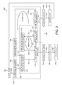
- a method 300 of determining the configuration of the rotorcraft 200 will now be described with reference to Figure 3 , and as further illustrated by Figures 4A-4C , 5A-5H , to 6A-6F.
- the method 300 begins at step 302 when the rotorcraft 200 lands on the landing pad 100.
- the rotorcraft 200 may locate the landing pad 100 in any conventional way.
- a landing event may be detected using any known method, for example using pressure sensitive switches, video monitoring, audio monitoring, and one or more radiation beams such as the breaking of a light beam.
- the method 300 then continues along line 303 to enter an outer loop 304 within which an inner loop 306 resides.
- the method proceeds to step 308, where the controller 190 configures the switching circuit such that a first tile 101 is connected to the positive connection 131 and becomes a positive tile.
- the first tile selected is the tile 101 in the lower left hand corner of the landing pad 100.
- the method 300 continues along line 309 to enter the inner loop 306 and proceeds to step 310.
- the controller 190 configures the switching circuit such that a first tile 102 is connected to the negative connection 132 and becomes a negative tile.
- the first tile selected as the negative tile is the tile to the right of the centre of the positive tile.
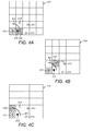
- Figure 4A shows this arrangement schematically.
- Figures 4A to 4C each show the landing pad 100 and the feet 211 to 214 of the rotorcraft 200 where the feet rest on the tiles 102, 103, 107 and 108 of the landing pad 100.
- Figure 4A shows tile 101 set as the positive tile and tile 102 set as the negative tile.
- the method 300 then proceeds along line 311 to step 312 where the circuit condition is tested.
- This line 311 to step 312 sees the controller 190 test the circuit formed between the positive and negative terminals of the power supply 170.
- a pass or fail condition is achieved or detected depending on the following.
- a pass condition is achieved when the positive tile and the negative tile are correctly located beneath the positive terminal 221 and the negative terminal 222 respectively of the rotorcraft 200. In this case, a complete circuit is formed and the controller 190 will register a closed circuit having the correct polarity. If the controller 190 determines a pass condition at step 312, the method continues along line 313 to step 314 where recharging of the battery 220 begins.
- a third fail condition corresponds to a short circuit caused by both the positive terminal 221 and the negative terminal 222 of the rotorcraft 200 resting on either the positive tile or the negative tile, such that the controller 190 determines a short circuit.
- the method may continue along path 328 to step 324 where the failed operation may be reported, and the rotorcraft 200 may then be prompted to take off at step 332 and attempt a further landing on the landing pad 100 at step 302.
- tile 102 beneath the negative terminal 222 is correctly set as the negative tile, but tile 101 that is set as the positive tile is not the tile beneath the positive terminal 221.
- the controller 190 determines a fail condition at step 312, and the method 300 continues around the inner loop 306 by proceeding to step 316 via line 315.
- the controller 190 maintains the connection to the positive tile, but reassigns the negative tile by moving the electrical connection from the power supply 170 from one tile 101 to 125 to the next.
- the separation of the positive terminal 221 and the negative terminal 222 of the rotorcraft 200 is chosen to be less than twice the width of each square tile 101 to 125 such that the positive and negative terminals 221 and 222 must reside on adjacent tiles 101 to 125.
- the controller 190 may simply reassign the negative tile to be each of the tiles adjacent the positive tile in turn.
- the controller 190 connects in turn each adjacent tile to the negative connection 132 in an anti-clockwise sequence.
- the controller 190 selects tiles 102, 107 and 106 in turn as the negative tile as indicated by arrow 401 in Figures 4A to 4C .
- the above explanation describes how the first positive tile is set at step 308, the first negative tile is set at step 310, the circuit condition test at step 312 is failed, and the method proceeds to step 316 where a further test is performed.
- the method at step 316 tests to see if all adjacent tiles have been set as the negative tile. Assuming this not to be the case, the method 300 continues along line 317 to step 318 where the controller 190 assigns the next adjacent tile (tile 107) as the negative tile. The method 300 then continues along line 319 back to step 312 where the circuit condition is again tested.
- the inner loop 306 sees further iterations of steps 316, 318 and 312 such that the controller 190 assigns in turn each of the adjacent tiles as the negative tile all the while the circuit condition test is failed at step 312. Eventually all tiles 102, 107 and 106 adjacent the positive tile 101 will be set as the negative tile. When the test step 312 is failed with the last tile 106 assigned as the negative tile, the outcome of test step 316 will indicate that the last tile in the negative tile sequence has been assigned. Thus, the method 300 exits the inner loop 306 via path 321 to allow a further iteration of the outer loop 304.
- each iteration of the outer loop 304 sees the controller 190 assign another tile 101 to 125 as the positive tile. This is performed by the method 300 progressing along line 321 to step 322 where an initial check is made to ensure that not all tiles 101 to 125 have already been assigned as the positive tile. That is, if step 322 determines that the last tile in the positive tile sequence is assigned as the positive tile, then all tile combinations have been tested without the configuration of the rotorcraft 200 having been determined. In this case, the method 300 exits the outer loop 325 by continuing along line 323 to step 324 where the controller 190 generates a report that the operation failed.
- the method 300 may then continue along line 330 to step 332 where a command is issued to the rotorcraft 200 to take off.
- the rotorcraft 200 duly takes off and lands once more on the landing pad 110, i.e. the method returns along line 334 to step 302 and another attempt is made to charge the battery 220 of the rotorcraft 200.
- Changing the orientation of the rotorcraft 200 on the landing pad 110 will increase the chances of the further charging attempt to be successful.
- the mere act of taking off, gaining a few feet in altitude and landing again will be enough to cause the rotorcraft 200 to adopt a different orientation on the landing pad 110, for example because of the effect of the wind on the rotorcraft 200.
- the rotorcraft 200 may be controlled to ensure it adopts a different orientation, for example by rotating the rotorcraft about a vertical axis, by any well known means.
- step 322 the description above was for the case that all tiles had been assigned as the positive tile.
- step 322 only the first tile 101 has been set as the positive tile so far, such that the outcome of test 322 is no (the last tile in the positive tile sequence is not assigned as the positive tile).
- the method 300 continues along line 325 to step 326 where the controller assigns the next tile as the positive tile.
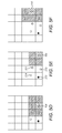
- the controller follows a sequence through the tiles 101 to 125 row by row, alternating from travelling from left to right to travelling from right to left, as shown in Figure 5A by the arrows 501.
- Figures 5A to 5H show schematically how the positive tiles are assigned in the outer loop 304, and also show all the negative tiles assigned during the iterations of each inner loop 306 for each iteration of the outer loop 304.
- the method 300 continues along line 327 to reenter the inner loop 306 by returning to step 310 where the controller 190 assigns the first tile as the negative tile.
- the first available tile according to the usual anti-clockwise sequence is assigned as the negative tile (tile 110).
- the inner loop 306 iterates with the controller 190 reassigning in turn the negative tile to the adjacent tiles 103, 108, 107, 106 and 101 all the while test step 312 indicates a fail condition.
- This is shown schematically in Figure 5B where all tiles 103, 108, 107, 106 and 101 are shown as assigned as the negative tile.
- each tile 101 to 125 may be, in principle, assigned in turn to be the positive tile. This is indicated in Figures 5a to 5h where it can be seen that the positive tile is reassigned to tiles 101, 102, 103, 104, 105, 110, 109 and then to tile 108.
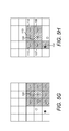
- Tile 108 is the tile upon which the positive terminal 221 of foot 211 rests. So, returning to method 300, the method will have proceeded to step 326 where the controller 190 has connected tile 108 to the positive connection 131 such that tile 108 is assigned as the positive tile. The method then joins the inner loop 306 once more at step 310 where the controller 190 first assigns tile 109 as the negative tile. This will result in test step 312 producing a fail condition, and so the inner loop 306 iterates through tiles 114, 113, 112 and 107 being assigned by the controller 190 as the negative tile as indicated in Figures 6A to 6E . In each iteration, test step 312 produces a fail condition.
- step 318 sees the controller assign tile 102 as the negative tile.
- the rotorcraft 200 has positive terminal 221 resting on tile 108 that is assigned to be the positive tile and negative terminal 222 resting on tile 102 that is assigned to be the negative tile, as indicated in Figure 6F .
- the controller 190 performs step 312
- a pass condition is obtained and the method 300 proceeds along line 313 to step 314 where, as described above, the battery 220 of the rotorcraft 200 is recharged, as indicated by line 336.
- step 338 a determination that the battery 220 is recharged is made, the determination of which is known in the art.
- the method proceeds along line 340 to step 342 where the rotorcraft 200 is instructed to or cleared for take off.
- the rotorcraft 200 may remain on the landing pad 100 for a period of time, or may depart as soon as the battery 220 is sufficiently recharged.
- the rotorcraft 200 may be landed on the landing pad 100 (this may be performed autonomously by the rotorcraft 200), and the recharging system 10 then autonomously determines the orientation of the rotorcraft 200 and configures the electrical connection of the appropriate tiles 101 to 125 to the power supply 170 to allow the battery 220 to be recharged.
- the rotorcraft 200 may take off to recommence its mission or to begin a new mission.
- a mission plan may include schedule stops at conveniently located recharging stations 10.
- the embodiments described above relate to an unmanned quadrotor, as an exemplary embodiment of rotorcraft 200.
- the invention may be practised with other rotorcraft and other aircraft including fixed wing aircraft.
- the aircraft may be manned or unmanned.
- the recharging station 10 may be used to recharge a variety of types of aircraft that visit the recharging station 10, and not just a single type. Additional power supplies may be provided such that a landing pad 100 may accommodate and recharge more than a single aircraft.
- the rotorcraft 200 described above are provided with four shielded rotors 201 to 204.
- Other configurations are possible, such as having from three to six rotors, and such as having unshielded rotors.
- the rotorcraft 200 described above are provided with feet 211 to 214 to provide support when the rotorcraft 200 is on the ground. Although embodiments with four feet have been described, other arrangements are possible such as three to six support legs and feet.
- the feet 211 to 214 provide a convenient means for housing the terminals 221 and 222.
- a pair of the feet 211, 212 is configured to mate electrically with a corresponding electrical terminal 221, 222 while the remaining feet 213 and 214 do not comprise electrical terminals on their underside.
- at least two and up to the entirety of the feet 211 to 214 may each include an associated electrical terminal, and may each be used as primary or redundant connections.
- the terminals 221 and 222 may be provided using conductive wheels or an extending member to contact the landing pad once in position on the parking pad.
- the separation of the positive and negative terminals 221 and 222 is greater than the diagonal distance across a square tile 101 to 125, but less than twice the width of a tile 101 to 125. This ensures that the two terminals 221 and 222 will contact adjacent tiles 101 to 125, thereby reducing the time required for the controller 190 to determine the configuration of the rotorcraft 200 because only adjacent tiles 101 to 125 need be set as the negative tile during the inner loop 306. Where this arrangement is not used, for example because a different type of aircraft positions itself on the landing pad 100, a fuller determination of the aircraft configuration may be performed by the controller 190. To test all combinations of tiles 101 to 125 as positive and negative tiles, the inner loop 306 may see a sequence where all tiles 101 to 125 other than the positive tile are set as the negative tile.
- the controller 190 may perform a further test at step 312 where the circuit condition is tested.
- the controller 190 may look for a closed circuit but also react if an incorrect polarity is determined. This situation corresponds to the tile 108 beneath the positive terminal 221 being set as the negative tile and the tile 102 beneath the negative terminal 222 being set as the positive tile. If this situation is found, the controller 190 may simply exit the inner loop 306 and the outer loop 308 and proceed to swap the tiles' connections to the positive and negative connections 131 and 132 such that the correct polarity is ensured. The method may then continue to step 314 where the rotorcraft 200 is recharged.
- the above methods may be modified such that the controller sets the negative tile in the outer loop 304 and sets the positive tile in the inner loop 306.
- the exemplary landing pad 100 described above has an array of twenty-five congruent square tiles 101 to 125 arranged to form a regular five by five grid with five rows and five columns. Other grid patterns and sizes are possible. Also, as noted above, the tiles 101 to 125 need not be square. Other polygons that tile readily may be chosen, such as triangles, squares, rectangles and hexagons. Irregular polygons and tiles with curved sides may be used. Tiles may have more than a single size and/or more than a single shape. For example, tiling maybe achieved using octagons and squares. Regular side-by side arrangements may be used, such as the array shown in the figures, although other arrangements such as a herringbone arrangement of rectangular tiles may be used.
Landscapes
- Engineering & Computer Science (AREA)
- Power Engineering (AREA)
- Transportation (AREA)
- Mechanical Engineering (AREA)
- Charge And Discharge Circuits For Batteries Or The Like (AREA)
Abstract
Description
- The present invention relates to an aircraft recharging pad and a method of recharging an aircraft. The present invention has particular application to the autonomous recharging of unmanned air vehicles.
- In its broadest sense, the present invention relates to recharging an aircraft battery. The battery may be provided in any type of aircraft, including rotorcraft and fixed-wing craft, and manned and unmanned aircraft. However, the present invention brings particular benefit to the field of unmanned air vehicles, particularly small unmanned air vehicles with limited battery life.
- There exists a problem with the battery life of relatively small unmanned air vehicles, for example those used in surveillance applications such as by the military, and police and fire fighting services. Quadrotors have become popular for such applications. These small unmanned air vehicles are rotorcraft that use four rotors mounted from a central body that carries surveillance equipment such as cameras (visible and/or infrared) and often computer memory to store still images or video collected.
- The battery operating time is a limiting factor for small unmanned air vehicles where a full charge of the battery may provide only 15 to 20 minutes flight time. This places undesirable restrictions on the types of missions the unmanned air vehicles may perform, and imposes a critical limitation for many surveillance applications.
- In the past, the problem of short battery life has been tackled from a battery design perspective, with improved battery design aimed at increasing battery life and/or reducing charging times. Other work has been performed on improving energy consumption of the unmanned air vehicles. The present invention may make use of such advances, such as using the latest generation of lithium polymer batteries, but the present invention is directed at an alternative approach to improving the utility of unmanned air vehicles. It will be appreciated that the present invention may bring the same benefit of improved recharging of a battery to other aircraft.
- Against this background and according to a first aspect, the present invention resides in an aircraft recharging station. The station comprises a parking surface disposed for an aircraft provided with a rechargeable battery to rest thereon. The parking surface comprises conductive tiles. An electrical connection circuit is provided that is configured to allow selectively an electrical connection between an electrical power supply and any two of any of the tiles. That is, from all the tiles, the electrical connection circuit can select any pair for connection to the power supply.
- The aircraft recharging station further comprises a controller arranged to determine the configuration of the aircraft on the parking surface to allow recharging of the battery by the power supply. The controller does this by repeatedly connecting pairs of the tiles to the power supply to provide a positive tile and a negative tile. The controller then tests the electrical circuit condition of the circuit connected to the power supply. The controller sets the tiles and tests the electrical circuit condition repeatedly until the correct circuit condition is determined, thereby indicating that the battery may be recharged.
- Optionally, the tiles are each provided with an electrical connector and each tile is insulated from the adjacent tiles. The power supply may comprise a positive terminal and a negative terminal. The electrical connection circuit may be configured to allow selectively an electrical connection between the positive power supply terminal and the electrical connector of any of the conducting tiles and to allow selectively an electrical connection between the negative power supply terminal and the electrical connector of any of the conducting tiles.
- The battery of the aircraft may be connected to a positive recharging terminal and a negative recharging terminal that are both arranged to be in contact with one or more of the conductive tiles when the aircraft is resting on the parking surface. For example, the position of the recharging terminals may be such that they contact the ground surface when the aircraft lands. Alternatively, the recharging terminals may be positioned such that they must be extended to contact the ground surface, for example when the aircraft has come to rest on the recharging station such that the recharging terminals then contact two of the conductive tiles.
- Optionally, the controller is arranged to determine the configuration of the aircraft using one or more setting steps and one or more testing steps, wherein a corresponding testing step is performed after each setting step. The setting step may comprise the controller using the electrical connection circuit to connect the positive power supply terminal to the electrical connector of one of the conductive tiles thereby making that tile the positive tile, and to use the electrical connection circuit to connect the negative power supply terminal to the electrical connector of another of the conductive tiles thereby making that the negative tile. The testing step may comprise the controller determining the electrical circuit condition between the positive and negative power supply terminals. Then, the controller may be arranged to repeat the setting step and the testing step as necessary until the correct circuit condition is determined, thereby indicating that the power supply is correctly connected to the positive and negative recharging terminals of the aircraft via the current positive and negative tiles.
- From a second aspect, the present invention resides in an aircraft recharging station for recharging an aircraft comprising a rechargeable battery connected to a positive recharging terminal and to a negative recharging terminal that both contact one or more of the conductive tiles when the aircraft is resting on the parking surface. The aircraft may be arranged such that the positive and negative recharging terminals always contact the ground surface when the aircraft rests on the ground surface, or the positive and negative recharging terminals may be selectively deployed to contact the ground surface. The battery may be a lithium polymer battery.
- The aircraft recharging station comprises a parking surface disposed for the aircraft to rest on, either because the aircraft lands on the parking surface or because the aircraft lands elsewhere and taxis to the parking surface. The parking surface comprises an array of conductive tiles each provided with an electrical connector. Hence, when the aircraft rests on the parking surface, the positive and negative recharging terminals may contact some of the conductive tiles. Each conductive tile is insulated from the other conductive tiles. The tiles may comprise metal or semi-conductor, and the conductor may be plate-like or may be a grid. The outer surface of the tiles may be conductive. Alternatively, inductive charging of the aircraft may be performed in which case the outer surface of the tiles may be an insulator.
- The aircraft recharging station further comprises an electrical power supply with a positive terminal and a negative terminal. An electrical connection circuit is provided that is configured to allow selectively an electrical connection between the positive power supply terminal and the electrical connector of any of the conducting tiles, and also to allow selectively an electrical connection between the negative power supply terminal and the electrical connector of any of the conducting tiles. Hence, any of the tiles may be connected to the positive terminal of the power supply and any of the tiles may be connected to the negative terminal of the power supply. However, as the tiles are insulated from each other, an open circuit exists when an aircraft is not present on the parking surface. This open circuit may be closed correctly by the aircraft if the aircraft is positioned on the parking surface with its positive recharging terminal contacting the tile connected to the positive power supply terminal and with its negative recharging terminal contacting the tile connected to the negative power supply terminal.
- Advantageously, the aircraft does not need to be positioned in a particular way to ensure coincidence of the recharging terminals to the correctly-connected tiles. Instead, appropriate tiles may be connected to the power supply to correspond to the orientation with which the aircraft is parked on the parking surface. The recharging station further comprises a controller arranged to determine the configuration of an aircraft on the parking surface to allow recharging of the aircraft by the power supply. The controller may be a suitably-programmed computer or an application-specific integrated circuit, hardware such as an electronic circuit arranged to operate in the required manner, or any other well-known equivalent.
- The controller is arranged to determine the configuration of the aircraft on the parking surface using one or more setting steps and one or more testing steps, wherein a testing step is performed after each setting step. In the setting step, the controller uses the electrical connection circuit to connect the positive power supply terminal to the electrical connector of one of the conductive tiles thereby making that tile a positive tile, and to use the electrical connection circuit to connect the negative power supply terminal to the electrical connector of another of the conductive tiles thereby making that tile a negative tile. In the testing step, the controller determines the electrical circuit condition between the positive and negative power supply terminals. The setting step and the testing step are repeated as necessary until the correct circuit condition is determined, thereby indicating that the power supply is correctly connected to the positive and negative recharging terminals of the aircraft via the currently-set positive and negative tiles. At each setting step, the controller selects a different tile to be the positive tile or selects a different tile to be the negative tile or selects different tiles to be the positive and negative tiles.
- The controller may be arranged to determine the electrical circuit condition between the positive and negative power supply terminals by determining whether an open circuit condition exists. This will be the case if one (or both) of the positive and negative recharging terminals of the aircraft is not contacting the positive or negative tiles. Such a circuit condition will be determined to be an incorrect circuit condition by the controller, and so the controller will proceed to the next setting step.
- The controller may determine that a short circuit condition exists (from the aircraft's perspective). This indicates that the positive and negative recharging terminals of the aircraft are in contact with the same tile (either the positive or negative tile), hence creating a short circuit. This again corresponds to an incorrect circuit condition. Rather than the controller proceeding to the next setting step, the controller may be arranged to report this configuration such that remedial action may be taken, such as repositioning the aircraft in an attempt to position the positive and negative recharging terminals over different tiles.
- The controller may determine that a closed circuit exists, indicating that the positive and negative recharging terminals are in contact with the positive and negative tiles. In some embodiments, the controller is arranged merely to report this as a correct circuit condition. In other embodiments, the controller is arranged to determine the polarity of the closed circuit. An incorrect circuit condition is determined by the controller if the wrong polarity is found, because the positive recharging terminal is in contact with the negative tile and the negative recharging terminal is in contact with the positive tile. In this case, the controller is arranged to proceed to the next setting step. A correct circuit condition is determined by the controller if the correct polarity is found, corresponding to the positive and negative recharging terminals being in contact with the positive and negative tiles respectively.
- Further advantageous but optional features will now be described. These optional features may be used with the aircraft recharging station according to either the first or second aspects of the present invention as have been described above.
- Optionally, the controller is arranged to determine the configuration of an aircraft on the parking surface iteratively using an inner loop and an outer loop. The outer loop may comprise the controller repeatedly setting the positive tile by using the electrical connection circuit to connect the positive power supply terminal to the electrical connector of each of the conductive tiles in turn, thereby potentially looping through all the tiles if the last tile set was in fact the tile under the positive recharging terminal of the aircraft. The inner loop may comprise after each time the controller has set the positive tile, the controller repeatedly setting the negative tile by using the electrical connection circuit to connect the negative power supply terminal to the electrical connector of each of the conductive tiles other than the positive tile in turn thereby looping through all of the tiles other than the positive tile. The controller may be arranged to repeat iterations of the outer loop and the inner loop until the correct circuit condition is determined.
- Rather than setting the positive tile in the outer loop and the negative tile in the inner loop, the negative tile may be set in the outer loop and the positive tile may be set in the inner loop. Thus, more generally, the outer loop may comprise the controller repeatedly setting either the positive tile or the negative tile by using the electrical connection circuit to connect the positive or negative power supply terminal respectively to the electrical connector of each of the conductive tiles in turn thereby potentially looping through all the tiles. The inner loop may comprise, after each time the controller has set the positive or negative tile, the controller repeatedly setting the other of the positive or negative tile by using the electrical connection circuit to connect the other of the positive or negative power supply terminal to the electrical connector of each of the conductive tiles other than the already-set positive or negative tile in turn thereby looping through all of the tiles other than the already-set tile. The controller may be arranged to repeat iterations of the outer loop and the inner loop until the correct circuit condition is determined.
- The parking surface may comprise an array of tiles arranged to fill the parking surface. That is to say, substantially no separation is left between tiles. In practice, a small separation must be left to ensure electrical isolation between the tiles. For example, narrow insulating strips may be used to provide a small separation between the tiles. The tiles may be regular or irregular shapes, although preferably shapes are chosen that may be tiled to leave no gaps. The tiles may be congruent and arranged in a repeating pattern. For example, the tiles may be triangular, square, rectangular or hexagonal in shape.
- In certain embodiments, the inner loop may comprise, after each time the controller has set the positive or negative tile in the outer loop, the controller repeatedly setting the other of the positive and negative tile by using the electrical connection circuit to connect the other of the positive or negative power supply terminal to the electrical connector of each of the conductive tiles adjacent to the already-set tile in turn, thereby potentially looping through all of the adjacent tiles. For example, when the positive tile is set in the outer loop, the inner loop may comprise, after each time the controller has set the positive tile in the outer loop, the controller repeatedly setting the negative tile by using the electrical connection circuit to connect the negative power supply terminal to the electrical connector of each of the conductive tiles adjacent to the positive tile in turn, thereby potentially looping through all of the adjacent tiles.
- The present invention also resides in the combination of an aircraft and any of the aircraft recharging stations described above subject to the parking surface comprising an array of congruent, square tiles. The aircraft comprises a positive recharging terminal that contacts the ground when the aircraft is resting on the ground and a negative recharging terminal that contacts the ground when the aircraft is resting on the ground. The battery may be a lithium polymer battery. The positive recharging terminal may be separated from the negative recharging terminal by a distance greater than the length of a diagonal across a tile of the parking surface but less than twice the width of a tile of the parking surface. Such an arrangement is advantageous when the controller is operable to perform the inner loop by setting only tiles adjacent the tile already-set in the outer loop, as described above. This is because the separation of the positive and negative recharging terminals ensures that they must contact adjacent tiles no matter how the aircraft is positioned on the parking surface.
- On the aircraft, landing feet or landing wheels may form the positive and negative recharging terminals of the aircraft. The aircraft may be any type of aircraft. For example, the aircraft may be manned or unmanned, fixed wing or rotorcraft.
- From a third aspect, the present invention resides in a method of recharging a rechargeable battery of an aircraft using a recharging station. The method may be computer-implemented.
- The recharging station comprises a parking surface disposed for the aircraft to park thereon, and the parking surface comprises conductive tiles.
- The method comprises determining the configuration of the aircraft on the parking surface by repeatedly connecting pairs of the tiles to an electrical power supply of the recharging station to provide a positive tile and a negative tile. The electrical circuit condition of the circuit connected to the power supply after each connection is made is then tested until the correct circuit condition is determined, thereby indicating that the battery may be recharged. The battery is then recharged using the power supply as correctly connected to the aircraft via the positive and negative tiles.
- The rechargeable battery may be connected to a positive recharging terminal and to a negative recharging terminal that are both arranged to contact the at least one of the conductive tiles when the aircraft is resting on the parking surface.
- The conductive tiles may be insulated from each other and the power supply, and the power supply may be provided with a positive terminal and a negative terminal.
- The method may comprise repeatedly connecting the positive terminal to a tile to provide the positive tile and connecting the negative terminal to a tile to provide the negative tile.
- Determining the configuration of the aircraft on the parking surface may comprise using one or more setting steps and one or more testing steps, such that a testing step is performed after each setting step. The setting step may comprise connecting the positive power supply terminal to one of the tiles thereby making that tile the positive tile, and connecting the negative power supply terminal to another of the conductive tiles thereby making that the negative tile. The testing step may comprise determining the electrical circuit condition between the positive and negative power supply terminals. The setting step and the testing step may be repeated as necessary until the correct circuit condition is determined, thereby indicating that the power supply is correctly connected to the positive and negative recharging terminals of the aircraft via the current positive and negative tiles.
- From a fourth aspect, the present invention resides in a method of recharging an aircraft using a recharging station. The method may be computer-implemented.
- The aircraft comprises a rechargeable battery connected to a positive recharging terminal that contacts the ground surface when the aircraft is resting on the ground surface and to a negative recharging terminal that contacts the ground when the aircraft is resting on the ground. The battery may be a lithium polymer battery.
- The aircraft recharging station comprises a parking surface disposed for an aircraft to rest thereon, the parking surface comprising an array of conductive tiles that are insulated from each other and a power supply with a positive terminal and a negative terminal. Each conductive tile is insulated from the other conductive tiles. The tiles may comprise metal or a semi-conductor, and the conductor may be plate-like or may be a grid. The outer surface of the tiles may be conductive. Alternatively, inductive charging of the aircraft may be performed in which case the outer surface of the tiles may be insulating.
- The method comprises determining the configuration of the aircraft on the parking surface using one or more setting steps and one or more testing steps, wherein a testing step is performed after each setting step. The setting step comprises connecting the positive power supply terminal to one of the conductive tiles thereby making that tile a positive tile, and connecting the negative power supply terminal to another of the conductive tiles thereby making that tile a negative tile. The testing step comprises determining the electrical circuit condition between the positive and negative power supply terminals. The setting step and the testing step are repeated as necessary until the correct circuit condition is determined, thereby indicating that the power supply is correctly connected to the positive and negative recharging terminals of the aircraft via the current positive and negative tiles. The method further comprises recharging the battery of the aircraft using the power supply as correctly connected to the aircraft via the current positive and negative tiles.
- Further advantageous but optional features will now be described. These optional features may be used with either the method according to the third aspect or the present invention or according to the fourth aspect of the present invention as have been described above.
- The method may comprise determining the electrical circuit condition between the positive and negative power supply terminals by determining whether an open circuit condition exists. This will be the case if either (or both) of the positive and negative recharging terminals of the aircraft is not contacting the positive or negative tiles. Such a circuit condition will be determined to be an incorrect circuit condition, and so the method will proceed to the next setting step.
- The method may comprise determining that a short circuit condition exists. This indicates that the positive and negative recharging terminals of the aircraft are in contact with the same tile (either the positive or negative tile). This again corresponds to an incorrect circuit condition. Rather than the method proceeding to the next setting step, the method may comprise reporting this configuration such that remedial action may be taken, such as repositioning the aircraft in an attempt to position the positive and negative recharging terminals over different tiles.
- The method may comprise determining that a closed circuit exists, indicating that the positive and negative recharging terminals are in contact with the positive and negative tiles. In some embodiments, this is merely reported as a correct circuit condition. In other embodiments, the polarity of the closed circuit is checked. An incorrect circuit condition is determined if the wrong polarity is found, because the positive recharging terminal is in contact with the negative tile and the negative recharging terminal is in contact with the positive tile. In this case, the method may proceed to the next setting step. A correct circuit condition is determined if the correct polarity is found, corresponding to the positive and negative recharging terminals being in contact with the positive and negative tiles respectively.
- The method may comprise determining the configuration of the aircraft on the parking surface iteratively using an inner loop and an outer loop. The outer loop may comprise repeatedly setting either the positive or negative tile by connecting the positive or negative power supply terminal respectively to each of the conductive tiles in turn, thereby potentially looping through all the tiles. The inner loop comprises, after each time the positive or negative tile is set, repeatedly setting the other of the positive and negative tile by connecting the other of the positive and negative power supply terminal to each of the conductive tiles other than the already-set tile in turn, thereby looping through all of the tiles other than the already-set tile. The method may comprise repeating iterations of the outer loop and the inner loop until the correct circuit condition is determined.
- Optionally, the inner loop comprises, after each time the positive or negative tile is set in the outer loop, repeatedly setting the other of the positive and negative tile by connecting the other of the positive and negative power supply terminal to each of the conductive tiles adjacent to the already-set tile in turn thereby looping through all of the adjacent tiles. This may be done by selecting the adjacent tiles in turn in a clockwise or anti-clockwise direction. In the outer loop, the method may comprise setting the positive or negative tile repeatedly by selecting the next positive or negative tile from one of the adjacent tiles of the previously-set positive or negative tile. This may be done in an ordered sequence.
- The outer loop may comprise setting the positive tile using the positive power supply terminal, and the inner loop then comprises setting the negative tile using the negative power supply terminal by selecting in turn the tiles adjacent to the positive tile. Alternatively, the outer loop may comprise setting the negative tile using the negative power supply terminal, and the inner loop then comprises setting the positive tile using the positive power supply terminal by selecting in turn the tiles adjacent to the negative tile.
- In order that the present invention may be more readily understood, preferred embodiments will now be described, by way of example only, with reference to the accompanying drawings in which:
-
Figure 1 is simplified representation of an unmanned rotorcraft stationed on a recharging pad during recharging at a recharging station, shown in perspective; -
Figure 2 corresponds toFigure 1 , but shown as a plan view; -
Figure 3 is a schematic representation of how the arrangement ofFigures 1 and2 may be used to recharge a battery of the rotorcraft; -
Figures 4A to 4C shows schematically the recharging pad and the landing feet of the rotorcraft ofFigures 1 and2 , and illustrates an inner loop of a sequence used to determine the configuration of the rotorcraft; -
Figures 5A to 5H shows schematically the recharging pad and the landing feet of the rotorcraft ofFigures 1 and2 , and illustrates an outer loop of a sequence used to determine the configuration of the rotorcraft; and -
Figures 6A to 6F shows schematically the recharging pad and the landing feet of the rotorcraft ofFigures 1 and2 , and illustrates an inner loop of a sequence used to determine the configuration of the rotorcraft, including the final step when the configuration is determined. - There follows a description of certain exemplary embodiments of the present invention. While these embodiments fall within the scope of the appended claims, they incorporate some features that may be varied without departing from the scope of the claims. Examples of variations that may be made are provided at the end of the detailed description of the invention.
-
Figures 1 and2 show simplified representations of anaircraft recharging station 10 for recharging unmanned air vehicles like therotorcraft 200 shown in the figures. In this example, therotorcraft 200 comprises amain body 210 from which are mounted four shieldedrotors 201 to 204 on foursupport arms 205 to 208. When on the ground, therotorcraft 200 is supported on fourfeet 211 to 214 that are attached to thebody 210 by legs. - Although not shown in the figure, the
body 210 of therotorcraft 200 houses various components that allow therotorcraft 200 to operate. These include a computer processor that may be programmed to co-ordinate operation of therotorcraft 200. For example, the processor may be programmed with mission plans and may then execute the mission plans by causing therotorcraft 200 to fly according to the flight plan defined in the mission plan. The processor may control each of the fourrotors 201 to 204 independently to move therotorcraft 200 in all directions. In this embodiment, each of therotors 201 to 204 is powered by an electric motor (not shown), although a single electric motor may power all therotors 201 to 204 (for example, via gears to alter the power delivered to each rotor). - Electrical power is supplied to the motors from a rechargeable lithium-polymer battery 220 (or other type of electrical storage device), also housed within the
body 210 as can be seen through the break-away section ofFigure 1 . Even where therotors 201 to 205 are not powered by electric motors, therotorcraft 200 may still require abattery 220 to provide electrical power, for example to power the processor. - One of the
feet 211 is provided on its underside with anelectrical terminal 221 that forms a positive connection to thebattery 220. Another of thefeet 212 is provided on its underside with anelectrical terminal 222 that forms a negative connection to thebattery 220. As described, the feet (211, 212) are configured to mate electrically with a corresponding electrical terminal (221, 222). In this embodiment, the remaining feet, 213 and 214, do not comprise electrical terminals on their underside. - As shown in the figures, the
feet 211 to 214 may be of a relatively large size to provide stability and to prevent sliding of therotorcraft 200 when on the rechargingstation 10 or on the ground. Thepositive terminal 221 and thenegative terminal 222 may have a much smaller size when compared to thefeet - The recharging
station 10 comprises a parking surface corresponding to alanding pad 110 formed, in this embodiment, of an array ofsquare tiles 101 to 125. Therotorcraft 200 may land directly on thelanding pad 110. The recharging station further comprises apower supply 170 and acontroller 190. - The
controller 190 is connected to thepower supply 170 viaconnection 192 such that thecontroller 190 can control operation of thepower supply 170. Thecontroller 190 is also connected to thelanding pad 100 via acable 191 that is received in asocket 133 of thelanding pad 100. This allows thecontroller 190 to control operation of thelanding pad 100 as will be described in more detail below. Thepower supply 170 is provided with positive and negative outputs that are connected to apositive connection 131 and anegative connection 132 of thelanding pad 100 respectively viacables - In this embodiment, the
landing pad 100 has an array of twenty-five congruentsquare tiles 101 to 125 arranged to form a regular five by five grid with five rows and five columns. Eachtile 101 to 125 is electrically conductive, and is separated from adjacent tiles with insulatingstrips 130 that extend between the rows and columns. For example, each tile may include a highly conductive surface, such as a metal layer, metal alloy, or metal coating, and the insulating strips may be made of non-conducting materials such as rubber or plastic. Because the landing pad may be exposed to adverse weather, the tiles may be composed of a corrosion-resistant material, such as gold or thin stainless steel. - The underside of each
tile 101 to 125 is provided with an electrical connector to provide a secure electrical connection for eachtile 101 to 125 to a switching circuit. The switching circuit is also connected to thepositive connection 131 and thenegative connection 132, and to thecontroller 190 viasocket 133. The switching circuit provides an electrical connection circuit: thecontroller 190 is configured to control the switching circuit such that eachtile 101 to 125 may be connected to either thepositive connection 131 or thenegative connection 132. In this way, thecontroller 190 may select any combination of twotiles 101 to 125 to be connected to thepositive connection 131 and thenegative connection 132 of thepower supply 170 thereby forming positive and negative tiles on thelanding pad 100. - These positive and negative tiles may be used to recharge the
battery 220 of therotorcraft 200 when the tiles are in contact with thepositive terminal 221 and thenegative terminal 222 of therotorcraft 200. However, advantageously, therotorcraft 200 does not have to land on thelanding pad 100 in a predetermined configuration. Therotorcraft 200 may land on thelanding pad 100 in any orientation, and thecontroller 190 will determine the configuration and arrange the electrical connections to thetiles 101 to 125 of thelanding pad 100 accordingly. - In this embodiment, the separation of the
positive terminal 221 and thenegative terminal 222 of therotorcraft 200 is chosen to be greater than the maximum extent of eachtile 101 to 125, i.e. the separation of theterminals tile 101 to 125. This ensures that therotorcraft 200 cannot land on thelanding pad 100 with bothterminals same tile 101 to 125. Although the larger size of thefeet 211 to 214 may mean one ormore feet 211 to 214overlap tiles 101 to 125, the small size of thepositive terminal 221 and thenegative terminal 222 means that the chances of either terminal 221 or 225 extending acrossadjacent tiles 101 to 125 is very small. In any event, the above-described separation of theterminals single tile 101 to 125 may not be in contact with both the rotorcraft's positive andnegative terminals more tiles 101 to 125, any single or any combination of the contactingtiles 101 to 125 may be used as the positive or negative tile to connect the overlappingterminal power supply 170. - A
method 300 of determining the configuration of therotorcraft 200 will now be described with reference toFigure 3 , and as further illustrated byFigures 4A-4C ,5A-5H , to6A-6F. Themethod 300 begins atstep 302 when therotorcraft 200 lands on thelanding pad 100. Therotorcraft 200 may locate thelanding pad 100 in any conventional way. A landing event may be detected using any known method, for example using pressure sensitive switches, video monitoring, audio monitoring, and one or more radiation beams such as the breaking of a light beam. - The
method 300 then continues alongline 303 to enter an outer loop 304 within which aninner loop 306 resides. The method proceeds to step 308, where thecontroller 190 configures the switching circuit such that afirst tile 101 is connected to thepositive connection 131 and becomes a positive tile. In this embodiment, the first tile selected is thetile 101 in the lower left hand corner of thelanding pad 100. - With the first positive tile selected at
step 308, themethod 300 continues alongline 309 to enter theinner loop 306 and proceeds to step 310. Atstep 310, thecontroller 190 configures the switching circuit such that afirst tile 102 is connected to thenegative connection 132 and becomes a negative tile. In this embodiment, the first tile selected as the negative tile is the tile to the right of the centre of the positive tile. -
Figure 4A shows this arrangement schematically.Figures 4A to 4C each show thelanding pad 100 and thefeet 211 to 214 of therotorcraft 200 where the feet rest on thetiles landing pad 100.Figure 4A showstile 101 set as the positive tile andtile 102 set as the negative tile. - The
method 300 then proceeds alongline 311 to step 312 where the circuit condition is tested. Thisline 311 to step 312 sees thecontroller 190 test the circuit formed between the positive and negative terminals of thepower supply 170. A pass or fail condition is achieved or detected depending on the following. - A pass condition is achieved when the positive tile and the negative tile are correctly located beneath the
positive terminal 221 and thenegative terminal 222 respectively of therotorcraft 200. In this case, a complete circuit is formed and thecontroller 190 will register a closed circuit having the correct polarity. If thecontroller 190 determines a pass condition atstep 312, the method continues alongline 313 to step 314 where recharging of thebattery 220 begins. - On the other hand, a fail condition is achieved in either of the following arrangements:
- (i) the positive tile is located beneath the
negative terminal 222 and the negative tile is located beneath thepositive terminal 221 such that a complete circuit is formed, and thecontroller 190 will determine a closed circuit but having an incorrect polarity; or - (ii) a connection fails to be made, either because one of the positive or negative tiles is set in a position that does not coincide with one of the
terminals terminals controller 190 will determine an open circuit. - In embodiments where
rotorcraft 200 has positive andnegative terminals tile 101 to 125, it is possible for a third fail condition. This fail condition corresponds to a short circuit caused by both thepositive terminal 221 and thenegative terminal 222 of therotorcraft 200 resting on either the positive tile or the negative tile, such that thecontroller 190 determines a short circuit. When a short circuit is detected because the positive andnegative terminals rotorcraft 200 are connected directly together, the method may continue alongpath 328 to step 324 where the failed operation may be reported, and therotorcraft 200 may then be prompted to take off atstep 332 and attempt a further landing on thelanding pad 100 atstep 302. - In the present case shown in
Figure 4A ,tile 102 beneath thenegative terminal 222 is correctly set as the negative tile, buttile 101 that is set as the positive tile is not the tile beneath thepositive terminal 221. Hence, thecontroller 190 determines a fail condition atstep 312, and themethod 300 continues around theinner loop 306 by proceeding to step 316 vialine 315. In theinner loop 306, thecontroller 190 maintains the connection to the positive tile, but reassigns the negative tile by moving the electrical connection from thepower supply 170 from onetile 101 to 125 to the next. In this embodiment, the separation of thepositive terminal 221 and thenegative terminal 222 of therotorcraft 200 is chosen to be less than twice the width of eachsquare tile 101 to 125 such that the positive andnegative terminals adjacent tiles 101 to 125. With this arrangement, thecontroller 190 may simply reassign the negative tile to be each of the tiles adjacent the positive tile in turn. Thecontroller 190 connects in turn each adjacent tile to thenegative connection 132 in an anti-clockwise sequence. Hence, in the present case wheretile 101 is selected as the positive tile, thecontroller 190 selectstiles arrow 401 inFigures 4A to 4C . - So returning to the
method 300, the above explanation describes how the first positive tile is set atstep 308, the first negative tile is set atstep 310, the circuit condition test atstep 312 is failed, and the method proceeds to step 316 where a further test is performed. The method atstep 316 tests to see if all adjacent tiles have been set as the negative tile. Assuming this not to be the case, themethod 300 continues alongline 317 to step 318 where thecontroller 190 assigns the next adjacent tile (tile 107) as the negative tile. Themethod 300 then continues alongline 319 back to step 312 where the circuit condition is again tested. - As will be appreciated, the
inner loop 306 sees further iterations ofsteps controller 190 assigns in turn each of the adjacent tiles as the negative tile all the while the circuit condition test is failed atstep 312. Eventually alltiles positive tile 101 will be set as the negative tile. When thetest step 312 is failed with thelast tile 106 assigned as the negative tile, the outcome oftest step 316 will indicate that the last tile in the negative tile sequence has been assigned. Thus, themethod 300 exits theinner loop 306 viapath 321 to allow a further iteration of the outer loop 304. - Each iteration of the outer loop 304 sees the
controller 190 assign anothertile 101 to 125 as the positive tile. This is performed by themethod 300 progressing alongline 321 to step 322 where an initial check is made to ensure that not alltiles 101 to 125 have already been assigned as the positive tile. That is, ifstep 322 determines that the last tile in the positive tile sequence is assigned as the positive tile, then all tile combinations have been tested without the configuration of therotorcraft 200 having been determined. In this case, themethod 300 exits theouter loop 325 by continuing alongline 323 to step 324 where thecontroller 190 generates a report that the operation failed. - Optionally, and as shown in
Figure 3 , themethod 300 may then continue alongline 330 to step 332 where a command is issued to therotorcraft 200 to take off. Therotorcraft 200 duly takes off and lands once more on thelanding pad 110, i.e. the method returns alongline 334 to step 302 and another attempt is made to charge thebattery 220 of therotorcraft 200. Changing the orientation of therotorcraft 200 on thelanding pad 110 will increase the chances of the further charging attempt to be successful. Often, the mere act of taking off, gaining a few feet in altitude and landing again will be enough to cause therotorcraft 200 to adopt a different orientation on thelanding pad 110, for example because of the effect of the wind on therotorcraft 200. Of course, therotorcraft 200 may be controlled to ensure it adopts a different orientation, for example by rotating the rotorcraft about a vertical axis, by any well known means. - Returning to step 322, the description above was for the case that all tiles had been assigned as the positive tile. Returning to the previous description, only the
first tile 101 has been set as the positive tile so far, such that the outcome oftest 322 is no (the last tile in the positive tile sequence is not assigned as the positive tile). In this case, themethod 300 continues alongline 325 to step 326 where the controller assigns the next tile as the positive tile. - In this embodiment, the controller follows a sequence through the
tiles 101 to 125 row by row, alternating from travelling from left to right to travelling from right to left, as shown inFigure 5A by thearrows 501.Figures 5A to 5H show schematically how the positive tiles are assigned in the outer loop 304, and also show all the negative tiles assigned during the iterations of eachinner loop 306 for each iteration of the outer loop 304. As can be seen inFigures 5A to 5H , tiles are selected according to thesequence 101 => 102 => 103 => 104 => 105 => 110 => 109 => 108 => 107 => 106 => 111 => 112 => 113 => 114 => 115 => 120 => 119 => 118 => 117 => 116 => 121 => 122 => 123 => 124 => 125. - With the
next tile 102 assigned as the positive tile atstep 326, themethod 300 continues along line 327 to reenter theinner loop 306 by returning to step 310 where thecontroller 190 assigns the first tile as the negative tile. This will be tile 103 remembering that the first tile assigned is the tile to the right of the centre of thepositive tile 102. For some positive tiles, liketile 105 being assigned as the positive tile as shown inFigure 5E , there is no tile to the right of centre: in this case, the first available tile according to the usual anti-clockwise sequence is assigned as the negative tile (tile 110). - With
tile 102 assigned as the positive tile, theinner loop 306 iterates with thecontroller 190 reassigning in turn the negative tile to theadjacent tiles while test step 312 indicates a fail condition. This is shown schematically inFigure 5B where alltiles - Each time the
inner loop 306 completes withouttest step 312 producing a pass condition, the outer loop 304 iterates such that eachtile 101 to 125 may be, in principle, assigned in turn to be the positive tile. This is indicated inFigures 5a to 5h where it can be seen that the positive tile is reassigned totiles -
Tile 108 is the tile upon which thepositive terminal 221 offoot 211 rests. So, returning tomethod 300, the method will have proceeded to step 326 where thecontroller 190 has connectedtile 108 to thepositive connection 131 such thattile 108 is assigned as the positive tile. The method then joins theinner loop 306 once more atstep 310 where thecontroller 190 first assignstile 109 as the negative tile. This will result intest step 312 producing a fail condition, and so theinner loop 306 iterates throughtiles controller 190 as the negative tile as indicated inFigures 6A to 6E . In each iteration,test step 312 produces a fail condition. However, eventually step 318 sees the controller assigntile 102 as the negative tile. Now, therotorcraft 200 haspositive terminal 221 resting ontile 108 that is assigned to be the positive tile andnegative terminal 222 resting ontile 102 that is assigned to be the negative tile, as indicated inFigure 6F . Thus, when thecontroller 190 performsstep 312, a pass condition is obtained and themethod 300 proceeds alongline 313 to step 314 where, as described above, thebattery 220 of therotorcraft 200 is recharged, as indicated byline 336. Atstep 338, a determination that thebattery 220 is recharged is made, the determination of which is known in the art. The method proceeds alongline 340 to step 342 where therotorcraft 200 is instructed to or cleared for take off. Therotorcraft 200 may remain on thelanding pad 100 for a period of time, or may depart as soon as thebattery 220 is sufficiently recharged. - Thus, an autonomous method of recharging the
battery 220 is realised. Therotorcraft 200 may be landed on the landing pad 100 (this may be performed autonomously by the rotorcraft 200), and therecharging system 10 then autonomously determines the orientation of therotorcraft 200 and configures the electrical connection of theappropriate tiles 101 to 125 to thepower supply 170 to allow thebattery 220 to be recharged. Once thebattery 220 is recharged, therotorcraft 200 may take off to recommence its mission or to begin a new mission. For example, a mission plan may include schedule stops at conveniently located rechargingstations 10. - The person skilled in the art will appreciate that variations may be made to the above described embodiments without departing from the scope of the invention defined by the appended claims.
- For example, the embodiments described above relate to an unmanned quadrotor, as an exemplary embodiment of
rotorcraft 200. However, the invention may be practised with other rotorcraft and other aircraft including fixed wing aircraft. The aircraft may be manned or unmanned. The rechargingstation 10 may be used to recharge a variety of types of aircraft that visit the rechargingstation 10, and not just a single type. Additional power supplies may be provided such that alanding pad 100 may accommodate and recharge more than a single aircraft. - The
rotorcraft 200 described above are provided with four shieldedrotors 201 to 204. Other configurations are possible, such as having from three to six rotors, and such as having unshielded rotors. - The
rotorcraft 200 described above are provided withfeet 211 to 214 to provide support when therotorcraft 200 is on the ground. Although embodiments with four feet have been described, other arrangements are possible such as three to six support legs and feet. Thefeet 211 to 214 provide a convenient means for housing theterminals feet electrical terminal feet feet 211 to 214 may each include an associated electrical terminal, and may each be used as primary or redundant connections. Where wheeled arrangements are used on aircraft, theterminals - An advantageous embodiment is described above where the separation of the positive and
negative terminals square tile 101 to 125, but less than twice the width of atile 101 to 125. This ensures that the twoterminals adjacent tiles 101 to 125, thereby reducing the time required for thecontroller 190 to determine the configuration of therotorcraft 200 because onlyadjacent tiles 101 to 125 need be set as the negative tile during theinner loop 306. Where this arrangement is not used, for example because a different type of aircraft positions itself on thelanding pad 100, a fuller determination of the aircraft configuration may be performed by thecontroller 190. To test all combinations oftiles 101 to 125 as positive and negative tiles, theinner loop 306 may see a sequence where alltiles 101 to 125 other than the positive tile are set as the negative tile. - The
controller 190 may perform a further test atstep 312 where the circuit condition is tested. Thecontroller 190 may look for a closed circuit but also react if an incorrect polarity is determined. This situation corresponds to thetile 108 beneath thepositive terminal 221 being set as the negative tile and thetile 102 beneath thenegative terminal 222 being set as the positive tile. If this situation is found, thecontroller 190 may simply exit theinner loop 306 and theouter loop 308 and proceed to swap the tiles' connections to the positive andnegative connections rotorcraft 200 is recharged. - The above methods may be modified such that the controller sets the negative tile in the outer loop 304 and sets the positive tile in the
inner loop 306. - The
exemplary landing pad 100 described above has an array of twenty-five congruentsquare tiles 101 to 125 arranged to form a regular five by five grid with five rows and five columns. Other grid patterns and sizes are possible. Also, as noted above, thetiles 101 to 125 need not be square. Other polygons that tile readily may be chosen, such as triangles, squares, rectangles and hexagons. Irregular polygons and tiles with curved sides may be used. Tiles may have more than a single size and/or more than a single shape. For example, tiling maybe achieved using octagons and squares. Regular side-by side arrangements may be used, such as the array shown in the figures, although other arrangements such as a herringbone arrangement of rectangular tiles may be used.
Claims (15)
- An aircraft recharging station comprising:a parking surface disposed for an aircraft provided with a rechargeable battery to rest thereon, the parking surface comprising conductive tiles;an electrical connection circuit configured to allow selectively an electrical connection between an electrical power supply and any two of any of the tiles;a controller arranged to determine the configuration of the aircraft on the parking surface to allow recharging of the battery by the power supply by repeatedly connecting pairs of the tiles to the power supply to provide a positive tile and a negative tile and testing an electrical circuit condition of the circuit connected to the power supply until the correct circuit condition is determined, thereby indicating that the battery may be recharged.
- The aircraft recharging station of claim 1, wherein:the tiles are each provided with an electrical connector and each tile is insulated from the adjacent tiles;the electrical power supply comprises a positive terminal and a negative terminal;the electrical connection circuit is configured to allow selectively an electrical connection between the electrical power supply and any two of any of the tiles by allowing selectively an electrical connection between the positive power supply terminal and the electrical connector of any of the conducting tiles and to allow selectively an electrical connection between the negative power supply terminal and the electrical connector of any of the conducting tiles.
- The aircraft recharging station of claim 2, for recharging the battery of the aircraft that is connected to a positive recharging terminal and a negative recharging terminal that are both arranged to be in contact with one or more of the conductive tiles when the aircraft is resting on the parking surface.
- The aircraft recharging station of claim 3, wherein:the controller is arranged to determine the configuration of the aircraft using one or more setting steps and one or more testing steps, wherein a corresponding testing step is performed after each setting step,wherein:the setting step comprises the controller using the electrical connection circuit to connect the positive power supply terminal to the electrical connector of one of the conductive tiles thereby making that tile the positive tile, and to use the electrical connection circuit to connect the negative power supply terminal to the electrical connector of another of the conductive tiles thereby making that the negative tile, andthe testing step comprises the controller determining the electrical circuit condition between the positive and negative power supply terminals, andthe controller is arranged to repeat the setting step and the testing step as necessary until the correct circuit condition is determined, thereby indicating that the power supply is correctly connected to the positive and negative recharging terminals of the aircraft via the current positive and negative tiles.
- The aircraft recharging station of claim 4, wherein the controller is arranged to determine the configuration of an aircraft on the parking surface iteratively using an inner loop and an outer loop, wherein
the outer loop comprises the controller repeatedly setting either the positive tile or the negative tile by using the electrical connection circuit to connect either the positive power supply terminal or the negative power supply terminal respectively to the electrical connector of each of the conductive tiles in turn thereby looping through all the tiles;
the inner loop comprises after each time the controller has set the positive or negative tile, the controller repeatedly setting the other of the positive or negative tile by using the electrical connection circuit to connect the other of the positive or negative power supply terminal to the electrical connector of each of the conductive tiles other than the already-set tile in turn thereby looping through all of the tiles other than the already-set tile; and
iterations of the outer loop and the inner loop are repeated until the correct circuit condition is determined. - The aircraft recharging station of any preceding claim, wherein the parking surface comprises an array of the tiles that are arranged to fill the parking surface.
- The aircraft recharging station of claim 6, wherein:the conductive tiles are congruent and arranged in a repeating pattern and, optionally,the controller is arranged such that the inner loop comprises, after each time the controller has set the positive or negative tile, the controller repeatedly sets the other of the positive and negative tile by using the electrical connection circuit to connect the other of the positive or negative power supply terminal to the electrical connector of each of the tiles adjacent to the already-set tile in turn thereby looping through all of the adjacent tiles.
- The combination of an aircraft and an aircraft recharging station, comprising:the recharging station of claim 7, wherein the tiles are squares; andan aircraft comprising a rechargeable battery connected to a positive recharging terminal and a negative recharging terminal that are both arranged to be in contact with one or more of the conductive tiles when the aircraft is resting on the parking surface,wherein the positive recharging terminal is separated from the negative recharging terminal by a distance greater than the length of a longest span across a tile of the parking surface but less than twice the width of a tile of the parking surface.
- The combination of claim 8, wherein landing feet or landing wheels form the positive and negative recharging terminals of the aircraft.
- A method of recharging a rechargeable battery of an aircraft using a recharging station comprising a parking surface disposed for the aircraft to park thereon, the parking surface comprising conductive tiles;
the method comprising:determining the configuration of the aircraft on the parking surface by repeatedly connecting pairs of the tiles to an electrical power supply of the recharging station to provide a positive tile and a negative tile and testing an electrical circuit condition of the circuit connected to the power supply until the correct circuit condition is determined, thereby indicating that the battery may be recharged; andrecharging the battery using the power supply as correctly connected to the aircraft via the positive and negative tiles. - The method of claim 10, wherein:the rechargeable battery is connected to a positive recharging terminal and to a negative recharging terminal that are both arranged to be in contact with one or more of the conductive tiles when the aircraft is resting on the parking surface when the aircraft is resting on the ground;the conductive tiles are insulated from each other and the power supply, and the power supply is provided with a positive terminal and a negative terminal; andthe method comprises repeatedly connecting pairs of the tiles to the power supply of the recharging station comprises connecting the positive terminal to a tile to provide the positive tile and connecting the negative terminal to a tile to provide the negative tile.
- The method of claim 11, wherein:determining the configuration of the aircraft on the parking surface comprises:using one or more setting steps and one or more testing steps, such that a testing step is performed after each setting step, and
the setting step comprises connecting the positive power supply terminal to one of the tiles thereby making that tile the positive tile, and connecting the negative power supply terminal to another of the conductive tiles thereby making that the negative tile, and
the testing step comprises determining the electrical circuit condition between the positive and negative power supply terminals; andrepeating the setting step and the testing step as necessary until the correct circuit condition is determined, thereby indicating that the power supply is correctly connected to the positive and negative recharging terminals of the aircraft via the current positive and negative tiles. - The method of claim 12, comprising determining the configuration of the aircraft on the parking surface iteratively using an inner loop and an outer loop, wherein
the outer loop comprises repeatedly setting either the positive tile or the negative tile by connecting the positive or negative power supply terminal respectively to each of the tiles in turn thereby looping through all the tiles;
the inner loop comprises, after each time the positive or negative tile is set, repeatedly setting the other of the positive and negative tile by connecting the other of the positive and negative power supply terminal to each of the tiles other than the already-set tile in turn thereby looping through all of the tiles other than the already-set tile; and
repeating iterations of the outer loop and the inner loop until the correct circuit condition is determined. - The method of claim 13, wherein the inner loop comprises, after each time the positive or negative tile is set in the outer loop, repeatedly setting the other of the positive and negative tile by connecting the other of the positive and negative power supply terminal to each of the conductive tiles adjacent to the already-set tile in turn thereby looping through all of the adjacent tiles.
- The method of claim 14 comprising:in the inner loop, setting the adjacent tiles as the other of the positive and negative tile by selecting the adjacent tiles in turn in a clockwise or anti-clockwise direction; and/orin the outer loop, setting the positive or negative tile repeatedly by selecting the next positive or negative tile from one of the adjacent tiles of the previously-set positive or negative tile.
Priority Applications (2)
| Application Number | Priority Date | Filing Date | Title |
|---|---|---|---|
| EP13382387.2A EP2858207B1 (en) | 2013-10-03 | 2013-10-03 | Recharging an aircraft battery |
| US14/461,761 US9643507B2 (en) | 2013-10-03 | 2014-08-18 | Recharging an aircraft battery |
Applications Claiming Priority (1)
| Application Number | Priority Date | Filing Date | Title |
|---|---|---|---|
| EP13382387.2A EP2858207B1 (en) | 2013-10-03 | 2013-10-03 | Recharging an aircraft battery |
Publications (2)
| Publication Number | Publication Date |
|---|---|
| EP2858207A1 true EP2858207A1 (en) | 2015-04-08 |
| EP2858207B1 EP2858207B1 (en) | 2018-07-11 |
Family
ID=49293570
Family Applications (1)
| Application Number | Title | Priority Date | Filing Date |
|---|---|---|---|
| EP13382387.2A Not-in-force EP2858207B1 (en) | 2013-10-03 | 2013-10-03 | Recharging an aircraft battery |
Country Status (2)
| Country | Link |
|---|---|
| US (1) | US9643507B2 (en) |
| EP (1) | EP2858207B1 (en) |
Cited By (8)
| Publication number | Priority date | Publication date | Assignee | Title |
|---|---|---|---|---|
| CN104909322A (en) * | 2015-05-10 | 2015-09-16 | 浙江空行飞行器技术有限公司 | Supply device of unmanned aerial vehicle |
| GB2529021A (en) * | 2014-05-30 | 2016-02-10 | Geola Technologies Ltd | Charging and re-provisioning station for electric and hybrid unmanned aerial vehicles. |
| GB2553604A (en) * | 2016-09-13 | 2018-03-14 | Al Lami Haider | A drone and drone recharging and storage station |
| CN108657430A (en) * | 2018-05-29 | 2018-10-16 | 马鞍山安慧智电子科技有限公司 | A kind of collapsible unmanned plane based on contact charging |
| CN108820237A (en) * | 2018-05-31 | 2018-11-16 | 智飞智能装备科技东台有限公司 | A kind of photovoltaic charged base station for unmanned plane |
| CN111094131A (en) * | 2017-07-19 | 2020-05-01 | Wing航空有限责任公司 | System for charging aircraft |
| CN111343609A (en) * | 2020-02-28 | 2020-06-26 | 西南电子技术研究所(中国电子科技集团公司第十研究所) | Unmanned aerial vehicle measurement and control chain power and rate combined control method |
| EP4139763A4 (en) * | 2021-02-01 | 2023-10-18 | Sagar Defence Engineering Private Limited | METHOD AND SYSTEM FOR DETERMINING THE POSITION OF A DRONE CASE FOR STABILIZED LANDING AND STARTING A DRONE |
Families Citing this family (39)
| Publication number | Priority date | Publication date | Assignee | Title |
|---|---|---|---|---|
| US9629220B2 (en) * | 2013-08-05 | 2017-04-18 | Peter Panopoulos | Sensor-based controllable LED lighting system with repositionable components and method |
| KR101571161B1 (en) * | 2015-01-13 | 2015-11-23 | 국방기술품질원 | Unmanned aerial vehicle, Charging station and Automatic charging system for Unmanned aerial vehicle comprising the same |
| US9902504B2 (en) * | 2015-02-04 | 2018-02-27 | Toyota Motor Engineering & Manufacturing North America, Inc. | Systems and methods for docking and charging unmanned aerial vehicles |
| US9828093B2 (en) * | 2015-05-27 | 2017-11-28 | First Principles, Inc. | System for recharging remotely controlled aerial vehicle, charging station and rechargeable remotely controlled aerial vehicle, and method of use thereof |
| US10633115B2 (en) * | 2015-08-17 | 2020-04-28 | Skyyfish, LLC | Autonomous system for unmanned aerial vehicle landing, charging and takeoff |
| US10790699B2 (en) * | 2015-09-24 | 2020-09-29 | Apple Inc. | Configurable wireless transmitter device |
| US10663529B1 (en) | 2015-09-25 | 2020-05-26 | Amazon Technologies, Inc. | Automatic battery charging |
| US10651685B1 (en) | 2015-09-30 | 2020-05-12 | Apple Inc. | Selective activation of a wireless transmitter device |
| WO2017057911A1 (en) * | 2015-10-01 | 2017-04-06 | 엘지이노텍 주식회사 | Wireless charging system for unmanned aerial vehicle, and method for operating same |
| WO2017062418A1 (en) | 2015-10-05 | 2017-04-13 | Asylon, Inc. | Methods and apparatus for reconfigurable power exchange for multiple uav types |
| US10532663B2 (en) | 2015-11-13 | 2020-01-14 | Nio Usa, Inc. | Electric vehicle overhead charging system and method of use |
| US20170136887A1 (en) * | 2015-11-13 | 2017-05-18 | NextEv USA, Inc. | Electric vehicle aerial vehicle charging system and method of use |
| US20170136881A1 (en) * | 2015-11-13 | 2017-05-18 | NextEv USA, Inc. | Vehicle to vehicle charging system and method of use |
| US10632852B2 (en) | 2015-11-13 | 2020-04-28 | Nio Usa, Inc. | Electric vehicle optical charging system and method of use |
| CN105416597A (en) * | 2015-12-07 | 2016-03-23 | 上海云犀智能系统有限公司 | Automatic charging device for unmanned aerial vehicle and unmanned aerial vehicle |
| US10734840B2 (en) | 2016-08-26 | 2020-08-04 | Apple Inc. | Shared power converter for a wireless transmitter device |
| US10112728B2 (en) * | 2016-09-09 | 2018-10-30 | Michael Steward Evans | Drone charging stations |
| US10427780B2 (en) * | 2016-10-20 | 2019-10-01 | Bell Helicopter Textron Inc. | Electric cold flow tipjet rotorcraft |
| CN106787231B (en) * | 2016-12-30 | 2023-09-22 | 伽行科技(北京)有限公司 | An automatic charging device for drones and a charging method thereof |
| US10594160B2 (en) | 2017-01-11 | 2020-03-17 | Apple Inc. | Noise mitigation in wireless power systems |
| DE102018112472A1 (en) * | 2017-10-17 | 2019-04-18 | easE-Link GmbH | Ground contact unit for a vehicle battery charging system and method for switching a contact area of a ground contact unit |
| US10953984B2 (en) | 2017-12-20 | 2021-03-23 | Wing Aviation Llc | Methods and systems for using an unmanned aerial vehicle (UAV) dedicated to deployment of operational infrastructure |
| US10894601B2 (en) | 2017-12-20 | 2021-01-19 | Wing Aviation Llc | Methods and systems for self-deployment of operational infrastructure by an unmanned aerial vehicle (UAV) |
| US11124314B2 (en) | 2018-04-12 | 2021-09-21 | The Boeing Company | Systems and methods for transferring electric power to an aircraft during flight |
| EP3738891A1 (en) | 2019-05-17 | 2020-11-18 | Fuvex Civil, SL | Landing platform for unmanned aerial vehicles |
| CN110816327B (en) * | 2019-10-18 | 2023-04-14 | 西北工业大学 | A Contact UAV Autonomous Charging System |
| US11005301B1 (en) | 2020-01-10 | 2021-05-11 | The Boeing Company | System and method for encrypted resonant inductive power transfer |
| WO2021188274A1 (en) | 2020-03-16 | 2021-09-23 | Asylon, Inc. | Automated alert system using unmanned aerial vehicles |
| CA3191056A1 (en) * | 2020-05-18 | 2021-11-25 | Chirag Shah | Method and system to ascertain location of drone box for landing and charging drones |
| CN111762040B (en) * | 2020-06-07 | 2023-08-18 | 中国葛洲坝集团第一工程有限公司 | Near-field relay unmanned aerial vehicle dangerous rock monitoring system and method |
| US11679875B2 (en) * | 2020-12-03 | 2023-06-20 | Saudi Arabian Oil Company | Mechanism for docking a magnetic crawler into a UAV |
| KR102598609B1 (en) * | 2021-03-11 | 2023-11-07 | 주식회사 이스온 | Charging system for drone |
| US11273724B1 (en) * | 2021-06-29 | 2022-03-15 | Beta Air, Llc | Recharging station for electric aircrafts and a method of its use |
| US11618331B1 (en) * | 2021-10-31 | 2023-04-04 | Beta Air, Llc | Proximity detection systems and methods for facilitating charging of electric aircraft |
| EP4293866A1 (en) * | 2022-06-16 | 2023-12-20 | GEOSTAT Aerospace & Technology Inc. | Apparatus and methods for providing charging power to an external device |
| US12344411B1 (en) * | 2024-04-03 | 2025-07-01 | Hoodman Corporation | Foldable launch and landing pad for drones |
| US12545447B1 (en) * | 2024-06-07 | 2026-02-10 | Amazon Technologies, Inc. | Aerial vehicle landing pad with sensors |
| US20260048877A1 (en) * | 2024-08-15 | 2026-02-19 | Skydio, Inc. | Base Station For An Unmanned Aerial Vehicle Including A Rotatable Roof Assembly |
| US20260048865A1 (en) * | 2024-08-15 | 2026-02-19 | Skydio, Inc. | Method of docking an unmanned aerial vehicle with a base station |
Citations (2)
| Publication number | Priority date | Publication date | Assignee | Title |
|---|---|---|---|---|
| KR20100050652A (en) * | 2008-11-06 | 2010-05-14 | 한국과학기술원 | Extensible system and method for recharging remote control mobile unit automatically |
| KR20100104113A (en) * | 2009-03-16 | 2010-09-29 | (주)두일 | Electric proof tile |
Family Cites Families (1)
| Publication number | Priority date | Publication date | Assignee | Title |
|---|---|---|---|---|
| CA2391252C (en) * | 2002-06-25 | 2010-08-10 | 21St Century Airships Inc. | Airship and method of operation |
-
2013
- 2013-10-03 EP EP13382387.2A patent/EP2858207B1/en not_active Not-in-force
-
2014
- 2014-08-18 US US14/461,761 patent/US9643507B2/en not_active Expired - Fee Related
Patent Citations (2)
| Publication number | Priority date | Publication date | Assignee | Title |
|---|---|---|---|---|
| KR20100050652A (en) * | 2008-11-06 | 2010-05-14 | 한국과학기술원 | Extensible system and method for recharging remote control mobile unit automatically |
| KR20100104113A (en) * | 2009-03-16 | 2010-09-29 | (주)두일 | Electric proof tile |
Cited By (14)
| Publication number | Priority date | Publication date | Assignee | Title |
|---|---|---|---|---|
| GB2529021A (en) * | 2014-05-30 | 2016-02-10 | Geola Technologies Ltd | Charging and re-provisioning station for electric and hybrid unmanned aerial vehicles. |
| GB2529021B (en) * | 2014-05-30 | 2016-11-02 | Neva Aerospace Ltd | Charging and re-provisioning station for electric and hybrid unmanned aerial vehicles. |
| GB2540052A (en) * | 2014-05-30 | 2017-01-04 | Neva Aerospace Ltd | Charging and re-provisioning station for electric and hybrid unmanned aerial vechicles |
| GB2540052B (en) * | 2014-05-30 | 2017-07-19 | Neva Aerospace Ltd | Charging and re-provisioning station for electric and hybrid unmanned aerial vechicles |
| CN104909322A (en) * | 2015-05-10 | 2015-09-16 | 浙江空行飞行器技术有限公司 | Supply device of unmanned aerial vehicle |
| GB2553604B (en) * | 2016-09-13 | 2019-06-12 | Haider Al Lami | Aerodynamically fully actuated drone (Sauceron) and drone chassis aerodynamic supporting trusses (Lings) |
| GB2553604A (en) * | 2016-09-13 | 2018-03-14 | Al Lami Haider | A drone and drone recharging and storage station |
| CN111094131A (en) * | 2017-07-19 | 2020-05-01 | Wing航空有限责任公司 | System for charging aircraft |
| CN111094131B (en) * | 2017-07-19 | 2023-06-16 | Wing航空有限责任公司 | System for charging an aircraft |
| CN108657430A (en) * | 2018-05-29 | 2018-10-16 | 马鞍山安慧智电子科技有限公司 | A kind of collapsible unmanned plane based on contact charging |
| CN108820237A (en) * | 2018-05-31 | 2018-11-16 | 智飞智能装备科技东台有限公司 | A kind of photovoltaic charged base station for unmanned plane |
| CN111343609A (en) * | 2020-02-28 | 2020-06-26 | 西南电子技术研究所(中国电子科技集团公司第十研究所) | Unmanned aerial vehicle measurement and control chain power and rate combined control method |
| CN111343609B (en) * | 2020-02-28 | 2022-09-02 | 西南电子技术研究所(中国电子科技集团公司第十研究所) | Unmanned aerial vehicle measurement and control chain power and rate combined control method |
| EP4139763A4 (en) * | 2021-02-01 | 2023-10-18 | Sagar Defence Engineering Private Limited | METHOD AND SYSTEM FOR DETERMINING THE POSITION OF A DRONE CASE FOR STABILIZED LANDING AND STARTING A DRONE |
Also Published As
| Publication number | Publication date |
|---|---|
| US9643507B2 (en) | 2017-05-09 |
| EP2858207B1 (en) | 2018-07-11 |
| US20150097530A1 (en) | 2015-04-09 |
Similar Documents
| Publication | Publication Date | Title |
|---|---|---|
| EP2858207B1 (en) | Recharging an aircraft battery | |
| US20260048841A1 (en) | Systems and methods for charging, transporting, and operating flying machines | |
| KR102084303B1 (en) | Drone recharging system and dron station with the same | |
| ES2956269T3 (en) | Landing platform for unmanned aerial vehicles | |
| KR101571161B1 (en) | Unmanned aerial vehicle, Charging station and Automatic charging system for Unmanned aerial vehicle comprising the same | |
| KR101851596B1 (en) | unmanned aerial vehicle and charging station for unmanned aerial vehicle | |
| US9828093B2 (en) | System for recharging remotely controlled aerial vehicle, charging station and rechargeable remotely controlled aerial vehicle, and method of use thereof | |
| EP3734792B1 (en) | Battery management system | |
| KR101883196B1 (en) | Vertical takeoff and landing drone and docking station | |
| CN110753662A (en) | Small satellites capable of flying in formation and formations of several small satellites | |
| CN106985695A (en) | A kind of charging system for electric automobile for being applicable to polytype multi-storied garage | |
| RU2593207C1 (en) | Method for charging accumulator batteries of unmanned aerial vehicles | |
| CN111404239B (en) | A porous charging panel of antiskid for unmanned aerial vehicle descending charges | |
| JP2020178463A (en) | Manufacturing method of power receiving antenna, sky mobile body, wireless power transmission system and power receiving antenna | |
| KR20200140032A (en) | Charging system for drone | |
| CN110816327A (en) | Contact unmanned aerial vehicle autonomous charging system | |
| Fetisov et al. | Charging stations with open contact pads for maintenance of aerial robots | |
| KR20180039032A (en) | unmanned aerial vehicle and charging station for unmanned aerial vehicle | |
| KR101902875B1 (en) | unmanned aerial vehicle and charging station for unmanned aerial vehicle | |
| US20170244263A1 (en) | Automated electrical charger for autonomous platforms | |
| RU228885U1 (en) | Transportable deployable platform for recharging batteries of aerial robots | |
| CN111267653A (en) | Rotor unmanned aerial vehicle charging device, charging system and charging method thereof | |
| CN116280351A (en) | A kind of unmanned aerial vehicle charging hangar and unmanned aerial vehicle | |
| Ben-Moshe | Power Line Charging Mechanism for Drones. Drones 2021, 5, 108 | |
| RU2657866C1 (en) | Battery charging system of unmanned aerial vehicle |
Legal Events
| Date | Code | Title | Description |
|---|---|---|---|
| PUAI | Public reference made under article 153(3) epc to a published international application that has entered the european phase |
Free format text: ORIGINAL CODE: 0009012 |
|
| 17P | Request for examination filed |
Effective date: 20131003 |
|
| AK | Designated contracting states |
Kind code of ref document: A1 Designated state(s): AL AT BE BG CH CY CZ DE DK EE ES FI FR GB GR HR HU IE IS IT LI LT LU LV MC MK MT NL NO PL PT RO RS SE SI SK SM TR |
|
| AX | Request for extension of the european patent |
Extension state: BA ME |
|
| 17Q | First examination report despatched |
Effective date: 20151223 |
|
| GRAP | Despatch of communication of intention to grant a patent |
Free format text: ORIGINAL CODE: EPIDOSNIGR1 |
|
| INTG | Intention to grant announced |
Effective date: 20180130 |
|
| GRAS | Grant fee paid |
Free format text: ORIGINAL CODE: EPIDOSNIGR3 |
|
| GRAA | (expected) grant |
Free format text: ORIGINAL CODE: 0009210 |
|
| AK | Designated contracting states |
Kind code of ref document: B1 Designated state(s): AL AT BE BG CH CY CZ DE DK EE ES FI FR GB GR HR HU IE IS IT LI LT LU LV MC MK MT NL NO PL PT RO RS SE SI SK SM TR |
|
| REG | Reference to a national code |
Ref country code: GB Ref legal event code: FG4D |
|
| REG | Reference to a national code |
Ref country code: CH Ref legal event code: EP |
|
| REG | Reference to a national code |
Ref country code: AT Ref legal event code: REF Ref document number: 1017931 Country of ref document: AT Kind code of ref document: T Effective date: 20180715 |
|
| REG | Reference to a national code |
Ref country code: IE Ref legal event code: FG4D |
|
| REG | Reference to a national code |
Ref country code: DE Ref legal event code: R096 Ref document number: 602013040043 Country of ref document: DE |
|
| REG | Reference to a national code |
Ref country code: FR Ref legal event code: PLFP Year of fee payment: 6 |
|
| REG | Reference to a national code |
Ref country code: NL Ref legal event code: MP Effective date: 20180711 |
|
| REG | Reference to a national code |
Ref country code: LT Ref legal event code: MG4D |
|
| REG | Reference to a national code |
Ref country code: AT Ref legal event code: MK05 Ref document number: 1017931 Country of ref document: AT Kind code of ref document: T Effective date: 20180711 |
|
| PG25 | Lapsed in a contracting state [announced via postgrant information from national office to epo] |
Ref country code: NL Free format text: LAPSE BECAUSE OF FAILURE TO SUBMIT A TRANSLATION OF THE DESCRIPTION OR TO PAY THE FEE WITHIN THE PRESCRIBED TIME-LIMIT Effective date: 20180711 |
|
| PG25 | Lapsed in a contracting state [announced via postgrant information from national office to epo] |
Ref country code: FI Free format text: LAPSE BECAUSE OF FAILURE TO SUBMIT A TRANSLATION OF THE DESCRIPTION OR TO PAY THE FEE WITHIN THE PRESCRIBED TIME-LIMIT Effective date: 20180711 Ref country code: RS Free format text: LAPSE BECAUSE OF FAILURE TO SUBMIT A TRANSLATION OF THE DESCRIPTION OR TO PAY THE FEE WITHIN THE PRESCRIBED TIME-LIMIT Effective date: 20180711 Ref country code: AT Free format text: LAPSE BECAUSE OF FAILURE TO SUBMIT A TRANSLATION OF THE DESCRIPTION OR TO PAY THE FEE WITHIN THE PRESCRIBED TIME-LIMIT Effective date: 20180711 Ref country code: IS Free format text: LAPSE BECAUSE OF FAILURE TO SUBMIT A TRANSLATION OF THE DESCRIPTION OR TO PAY THE FEE WITHIN THE PRESCRIBED TIME-LIMIT Effective date: 20181111 Ref country code: NO Free format text: LAPSE BECAUSE OF FAILURE TO SUBMIT A TRANSLATION OF THE DESCRIPTION OR TO PAY THE FEE WITHIN THE PRESCRIBED TIME-LIMIT Effective date: 20181011 Ref country code: BG Free format text: LAPSE BECAUSE OF FAILURE TO SUBMIT A TRANSLATION OF THE DESCRIPTION OR TO PAY THE FEE WITHIN THE PRESCRIBED TIME-LIMIT Effective date: 20181011 Ref country code: SE Free format text: LAPSE BECAUSE OF FAILURE TO SUBMIT A TRANSLATION OF THE DESCRIPTION OR TO PAY THE FEE WITHIN THE PRESCRIBED TIME-LIMIT Effective date: 20180711 Ref country code: PL Free format text: LAPSE BECAUSE OF FAILURE TO SUBMIT A TRANSLATION OF THE DESCRIPTION OR TO PAY THE FEE WITHIN THE PRESCRIBED TIME-LIMIT Effective date: 20180711 Ref country code: LT Free format text: LAPSE BECAUSE OF FAILURE TO SUBMIT A TRANSLATION OF THE DESCRIPTION OR TO PAY THE FEE WITHIN THE PRESCRIBED TIME-LIMIT Effective date: 20180711 |
|
| PG25 | Lapsed in a contracting state [announced via postgrant information from national office to epo] |
Ref country code: ES Free format text: LAPSE BECAUSE OF FAILURE TO SUBMIT A TRANSLATION OF THE DESCRIPTION OR TO PAY THE FEE WITHIN THE PRESCRIBED TIME-LIMIT Effective date: 20180711 Ref country code: AL Free format text: LAPSE BECAUSE OF FAILURE TO SUBMIT A TRANSLATION OF THE DESCRIPTION OR TO PAY THE FEE WITHIN THE PRESCRIBED TIME-LIMIT Effective date: 20180711 Ref country code: LV Free format text: LAPSE BECAUSE OF FAILURE TO SUBMIT A TRANSLATION OF THE DESCRIPTION OR TO PAY THE FEE WITHIN THE PRESCRIBED TIME-LIMIT Effective date: 20180711 Ref country code: HR Free format text: LAPSE BECAUSE OF FAILURE TO SUBMIT A TRANSLATION OF THE DESCRIPTION OR TO PAY THE FEE WITHIN THE PRESCRIBED TIME-LIMIT Effective date: 20180711 |
|
| REG | Reference to a national code |
Ref country code: DE Ref legal event code: R097 Ref document number: 602013040043 Country of ref document: DE |
|
| PG25 | Lapsed in a contracting state [announced via postgrant information from national office to epo] |
Ref country code: CZ Free format text: LAPSE BECAUSE OF FAILURE TO SUBMIT A TRANSLATION OF THE DESCRIPTION OR TO PAY THE FEE WITHIN THE PRESCRIBED TIME-LIMIT Effective date: 20180711 Ref country code: RO Free format text: LAPSE BECAUSE OF FAILURE TO SUBMIT A TRANSLATION OF THE DESCRIPTION OR TO PAY THE FEE WITHIN THE PRESCRIBED TIME-LIMIT Effective date: 20180711 Ref country code: IT Free format text: LAPSE BECAUSE OF FAILURE TO SUBMIT A TRANSLATION OF THE DESCRIPTION OR TO PAY THE FEE WITHIN THE PRESCRIBED TIME-LIMIT Effective date: 20180711 Ref country code: EE Free format text: LAPSE BECAUSE OF FAILURE TO SUBMIT A TRANSLATION OF THE DESCRIPTION OR TO PAY THE FEE WITHIN THE PRESCRIBED TIME-LIMIT Effective date: 20180711 |
|
| PLBE | No opposition filed within time limit |
Free format text: ORIGINAL CODE: 0009261 |
|
| STAA | Information on the status of an ep patent application or granted ep patent |
Free format text: STATUS: NO OPPOSITION FILED WITHIN TIME LIMIT |
|
| PG25 | Lapsed in a contracting state [announced via postgrant information from national office to epo] |
Ref country code: DK Free format text: LAPSE BECAUSE OF FAILURE TO SUBMIT A TRANSLATION OF THE DESCRIPTION OR TO PAY THE FEE WITHIN THE PRESCRIBED TIME-LIMIT Effective date: 20180711 Ref country code: SM Free format text: LAPSE BECAUSE OF FAILURE TO SUBMIT A TRANSLATION OF THE DESCRIPTION OR TO PAY THE FEE WITHIN THE PRESCRIBED TIME-LIMIT Effective date: 20180711 Ref country code: SK Free format text: LAPSE BECAUSE OF FAILURE TO SUBMIT A TRANSLATION OF THE DESCRIPTION OR TO PAY THE FEE WITHIN THE PRESCRIBED TIME-LIMIT Effective date: 20180711 |
|
| REG | Reference to a national code |
Ref country code: CH Ref legal event code: PL |
|
| 26N | No opposition filed |
Effective date: 20190412 |
|
| REG | Reference to a national code |
Ref country code: BE Ref legal event code: MM Effective date: 20181031 |
|
| PG25 | Lapsed in a contracting state [announced via postgrant information from national office to epo] |
Ref country code: MC Free format text: LAPSE BECAUSE OF FAILURE TO SUBMIT A TRANSLATION OF THE DESCRIPTION OR TO PAY THE FEE WITHIN THE PRESCRIBED TIME-LIMIT Effective date: 20180711 Ref country code: LU Free format text: LAPSE BECAUSE OF NON-PAYMENT OF DUE FEES Effective date: 20181003 |
|
| REG | Reference to a national code |
Ref country code: IE Ref legal event code: MM4A |
|
| PG25 | Lapsed in a contracting state [announced via postgrant information from national office to epo] |
Ref country code: CH Free format text: LAPSE BECAUSE OF NON-PAYMENT OF DUE FEES Effective date: 20181031 Ref country code: LI Free format text: LAPSE BECAUSE OF NON-PAYMENT OF DUE FEES Effective date: 20181031 Ref country code: SI Free format text: LAPSE BECAUSE OF FAILURE TO SUBMIT A TRANSLATION OF THE DESCRIPTION OR TO PAY THE FEE WITHIN THE PRESCRIBED TIME-LIMIT Effective date: 20180711 Ref country code: BE Free format text: LAPSE BECAUSE OF NON-PAYMENT OF DUE FEES Effective date: 20181031 |
|
| PG25 | Lapsed in a contracting state [announced via postgrant information from national office to epo] |
Ref country code: IE Free format text: LAPSE BECAUSE OF NON-PAYMENT OF DUE FEES Effective date: 20181003 |
|
| REG | Reference to a national code |
Ref country code: DE Ref legal event code: R082 Ref document number: 602013040043 Country of ref document: DE Representative=s name: MAIER, LL.M., MICHAEL C., DE Ref country code: DE Ref legal event code: R082 Ref document number: 602013040043 Country of ref document: DE Representative=s name: BOULT WADE TENNANT LLP, DE |
|
| PG25 | Lapsed in a contracting state [announced via postgrant information from national office to epo] |
Ref country code: MT Free format text: LAPSE BECAUSE OF NON-PAYMENT OF DUE FEES Effective date: 20181003 |
|
| REG | Reference to a national code |
Ref country code: DE Ref legal event code: R082 Ref document number: 602013040043 Country of ref document: DE Representative=s name: BOULT WADE TENNANT LLP, DE |
|
| PG25 | Lapsed in a contracting state [announced via postgrant information from national office to epo] |
Ref country code: TR Free format text: LAPSE BECAUSE OF FAILURE TO SUBMIT A TRANSLATION OF THE DESCRIPTION OR TO PAY THE FEE WITHIN THE PRESCRIBED TIME-LIMIT Effective date: 20180711 |
|
| PG25 | Lapsed in a contracting state [announced via postgrant information from national office to epo] |
Ref country code: HU Free format text: LAPSE BECAUSE OF FAILURE TO SUBMIT A TRANSLATION OF THE DESCRIPTION OR TO PAY THE FEE WITHIN THE PRESCRIBED TIME-LIMIT; INVALID AB INITIO Effective date: 20131003 Ref country code: PT Free format text: LAPSE BECAUSE OF FAILURE TO SUBMIT A TRANSLATION OF THE DESCRIPTION OR TO PAY THE FEE WITHIN THE PRESCRIBED TIME-LIMIT Effective date: 20180711 |
|
| PG25 | Lapsed in a contracting state [announced via postgrant information from national office to epo] |
Ref country code: GR Free format text: LAPSE BECAUSE OF FAILURE TO SUBMIT A TRANSLATION OF THE DESCRIPTION OR TO PAY THE FEE WITHIN THE PRESCRIBED TIME-LIMIT Effective date: 20180711 Ref country code: CY Free format text: LAPSE BECAUSE OF FAILURE TO SUBMIT A TRANSLATION OF THE DESCRIPTION OR TO PAY THE FEE WITHIN THE PRESCRIBED TIME-LIMIT Effective date: 20180711 Ref country code: MK Free format text: LAPSE BECAUSE OF NON-PAYMENT OF DUE FEES Effective date: 20180711 |
|
| P01 | Opt-out of the competence of the unified patent court (upc) registered |
Effective date: 20230516 |
|
| PGFP | Annual fee paid to national office [announced via postgrant information from national office to epo] |
Ref country code: GB Payment date: 20231027 Year of fee payment: 11 |
|
| PGFP | Annual fee paid to national office [announced via postgrant information from national office to epo] |
Ref country code: FR Payment date: 20231025 Year of fee payment: 11 Ref country code: DE Payment date: 20231027 Year of fee payment: 11 |
|
| REG | Reference to a national code |
Ref country code: DE Ref legal event code: R119 Ref document number: 602013040043 Country of ref document: DE |
|
| GBPC | Gb: european patent ceased through non-payment of renewal fee |
Effective date: 20241003 |
|
| PG25 | Lapsed in a contracting state [announced via postgrant information from national office to epo] |
Ref country code: DE Free format text: LAPSE BECAUSE OF NON-PAYMENT OF DUE FEES Effective date: 20250501 |
|
| PG25 | Lapsed in a contracting state [announced via postgrant information from national office to epo] |
Ref country code: GB Free format text: LAPSE BECAUSE OF NON-PAYMENT OF DUE FEES Effective date: 20241003 |
|
| PG25 | Lapsed in a contracting state [announced via postgrant information from national office to epo] |
Ref country code: FR Free format text: LAPSE BECAUSE OF NON-PAYMENT OF DUE FEES Effective date: 20241031 |