EP2857746A1 - Advanced ultra supercritical steam generator - Google Patents
Advanced ultra supercritical steam generator Download PDFInfo
- Publication number
- EP2857746A1 EP2857746A1 EP14187421.4A EP14187421A EP2857746A1 EP 2857746 A1 EP2857746 A1 EP 2857746A1 EP 14187421 A EP14187421 A EP 14187421A EP 2857746 A1 EP2857746 A1 EP 2857746A1
- Authority
- EP
- European Patent Office
- Prior art keywords
- enclosure
- steam
- steam generator
- convection pass
- flue gas
- Prior art date
- Legal status (The legal status is an assumption and is not a legal conclusion. Google has not performed a legal analysis and makes no representation as to the accuracy of the status listed.)
- Granted
Links
- UGFAIRIUMAVXCW-UHFFFAOYSA-N Carbon monoxide Chemical compound [O+]#[C-] UGFAIRIUMAVXCW-UHFFFAOYSA-N 0.000 claims abstract description 79
- 239000003546 flue gas Substances 0.000 claims abstract description 74
- XLYOFNOQVPJJNP-UHFFFAOYSA-N water Substances O XLYOFNOQVPJJNP-UHFFFAOYSA-N 0.000 claims description 52
- 239000007789 gas Substances 0.000 claims description 51
- 239000012530 fluid Substances 0.000 claims description 19
- 239000002893 slag Substances 0.000 claims description 12
- 230000001172 regenerating effect Effects 0.000 claims description 9
- 239000011819 refractory material Substances 0.000 claims description 5
- 238000004140 cleaning Methods 0.000 claims description 4
- 239000012809 cooling fluid Substances 0.000 claims description 3
- 230000005611 electricity Effects 0.000 abstract description 4
- 239000002956 ash Substances 0.000 description 12
- 238000002485 combustion reaction Methods 0.000 description 10
- 238000010438 heat treatment Methods 0.000 description 8
- 239000003245 coal Substances 0.000 description 7
- 239000000203 mixture Substances 0.000 description 5
- 238000012546 transfer Methods 0.000 description 4
- CURLTUGMZLYLDI-UHFFFAOYSA-N Carbon dioxide Chemical compound O=C=O CURLTUGMZLYLDI-UHFFFAOYSA-N 0.000 description 3
- 239000011449 brick Substances 0.000 description 3
- 238000001816 cooling Methods 0.000 description 3
- 238000013461 design Methods 0.000 description 3
- 239000000446 fuel Substances 0.000 description 3
- 239000007788 liquid Substances 0.000 description 3
- 239000000463 material Substances 0.000 description 3
- 238000000034 method Methods 0.000 description 3
- 230000004048 modification Effects 0.000 description 3
- 238000012986 modification Methods 0.000 description 3
- 239000007787 solid Substances 0.000 description 3
- 238000011144 upstream manufacturing Methods 0.000 description 3
- VYPSYNLAJGMNEJ-UHFFFAOYSA-N Silicium dioxide Chemical compound O=[Si]=O VYPSYNLAJGMNEJ-UHFFFAOYSA-N 0.000 description 2
- 229910000831 Steel Inorganic materials 0.000 description 2
- 230000004075 alteration Effects 0.000 description 2
- 239000006227 byproduct Substances 0.000 description 2
- 229910002092 carbon dioxide Inorganic materials 0.000 description 2
- 239000001569 carbon dioxide Substances 0.000 description 2
- 229910002091 carbon monoxide Inorganic materials 0.000 description 2
- 230000006870 function Effects 0.000 description 2
- 229930195733 hydrocarbon Natural products 0.000 description 2
- 150000002430 hydrocarbons Chemical class 0.000 description 2
- 238000012423 maintenance Methods 0.000 description 2
- 239000012528 membrane Substances 0.000 description 2
- VNWKTOKETHGBQD-UHFFFAOYSA-N methane Chemical compound C VNWKTOKETHGBQD-UHFFFAOYSA-N 0.000 description 2
- 239000002245 particle Substances 0.000 description 2
- 230000008569 process Effects 0.000 description 2
- 229920006395 saturated elastomer Polymers 0.000 description 2
- 239000010959 steel Substances 0.000 description 2
- 239000000126 substance Substances 0.000 description 2
- OKTJSMMVPCPJKN-UHFFFAOYSA-N Carbon Chemical compound [C] OKTJSMMVPCPJKN-UHFFFAOYSA-N 0.000 description 1
- 229910000990 Ni alloy Inorganic materials 0.000 description 1
- 238000010521 absorption reaction Methods 0.000 description 1
- 239000002253 acid Substances 0.000 description 1
- 229910052785 arsenic Inorganic materials 0.000 description 1
- RQNWIZPPADIBDY-UHFFFAOYSA-N arsenic atom Chemical compound [As] RQNWIZPPADIBDY-UHFFFAOYSA-N 0.000 description 1
- QVGXLLKOCUKJST-UHFFFAOYSA-N atomic oxygen Chemical compound [O] QVGXLLKOCUKJST-UHFFFAOYSA-N 0.000 description 1
- 230000015572 biosynthetic process Effects 0.000 description 1
- 238000009835 boiling Methods 0.000 description 1
- 229910052799 carbon Inorganic materials 0.000 description 1
- 238000010531 catalytic reduction reaction Methods 0.000 description 1
- 239000000919 ceramic Substances 0.000 description 1
- 230000008859 change Effects 0.000 description 1
- 239000000567 combustion gas Substances 0.000 description 1
- 150000001875 compounds Chemical class 0.000 description 1
- 239000012141 concentrate Substances 0.000 description 1
- 239000002826 coolant Substances 0.000 description 1
- 230000001419 dependent effect Effects 0.000 description 1
- 238000006477 desulfuration reaction Methods 0.000 description 1
- 230000023556 desulfurization Effects 0.000 description 1
- 238000010586 diagram Methods 0.000 description 1
- 239000002283 diesel fuel Substances 0.000 description 1
- 239000012717 electrostatic precipitator Substances 0.000 description 1
- 238000005516 engineering process Methods 0.000 description 1
- 238000010304 firing Methods 0.000 description 1
- 239000010881 fly ash Substances 0.000 description 1
- 230000004927 fusion Effects 0.000 description 1
- 230000005484 gravity Effects 0.000 description 1
- 238000009413 insulation Methods 0.000 description 1
- 239000000395 magnesium oxide Substances 0.000 description 1
- CPLXHLVBOLITMK-UHFFFAOYSA-N magnesium oxide Inorganic materials [Mg]=O CPLXHLVBOLITMK-UHFFFAOYSA-N 0.000 description 1
- AXZKOIWUVFPNLO-UHFFFAOYSA-N magnesium;oxygen(2-) Chemical compound [O-2].[Mg+2] AXZKOIWUVFPNLO-UHFFFAOYSA-N 0.000 description 1
- 238000000691 measurement method Methods 0.000 description 1
- 230000005499 meniscus Effects 0.000 description 1
- QSHDDOUJBYECFT-UHFFFAOYSA-N mercury Chemical compound [Hg] QSHDDOUJBYECFT-UHFFFAOYSA-N 0.000 description 1
- 229910052753 mercury Inorganic materials 0.000 description 1
- 229910052751 metal Inorganic materials 0.000 description 1
- 239000002184 metal Substances 0.000 description 1
- 150000002739 metals Chemical class 0.000 description 1
- 239000003607 modifier Substances 0.000 description 1
- 239000003345 natural gas Substances 0.000 description 1
- TWNQGVIAIRXVLR-UHFFFAOYSA-N oxo(oxoalumanyloxy)alumane Chemical compound O=[Al]O[Al]=O TWNQGVIAIRXVLR-UHFFFAOYSA-N 0.000 description 1
- 229910052760 oxygen Inorganic materials 0.000 description 1
- 239000001301 oxygen Substances 0.000 description 1
- 238000010248 power generation Methods 0.000 description 1
- 239000000047 product Substances 0.000 description 1
- 230000009467 reduction Effects 0.000 description 1
- 238000006722 reduction reaction Methods 0.000 description 1
- 230000000630 rising effect Effects 0.000 description 1
- 238000007789 sealing Methods 0.000 description 1
- 230000009919 sequestration Effects 0.000 description 1
- 239000000377 silicon dioxide Substances 0.000 description 1
- 230000003068 static effect Effects 0.000 description 1
- 238000005496 tempering Methods 0.000 description 1
Images


Classifications
-
- F—MECHANICAL ENGINEERING; LIGHTING; HEATING; WEAPONS; BLASTING
- F23—COMBUSTION APPARATUS; COMBUSTION PROCESSES
- F23B—METHODS OR APPARATUS FOR COMBUSTION USING ONLY SOLID FUEL
- F23B7/00—Combustion techniques; Other solid-fuel combustion apparatus
- F23B7/002—Combustion techniques; Other solid-fuel combustion apparatus characterised by gas flow arrangements
- F23B7/005—Combustion techniques; Other solid-fuel combustion apparatus characterised by gas flow arrangements with downdraught through fuel bed and grate
-
- F—MECHANICAL ENGINEERING; LIGHTING; HEATING; WEAPONS; BLASTING
- F22—STEAM GENERATION
- F22B—METHODS OF STEAM GENERATION; STEAM BOILERS
- F22B21/00—Water-tube boilers of vertical or steeply-inclined type, i.e. the water-tube sets being arranged vertically or substantially vertically
- F22B21/34—Water-tube boilers of vertical or steeply-inclined type, i.e. the water-tube sets being arranged vertically or substantially vertically built-up from water tubes grouped in panel form surrounding the combustion chamber, i.e. radiation boilers
- F22B21/348—Radiation boilers with a burner at the top
-
- F—MECHANICAL ENGINEERING; LIGHTING; HEATING; WEAPONS; BLASTING
- F22—STEAM GENERATION
- F22B—METHODS OF STEAM GENERATION; STEAM BOILERS
- F22B29/00—Steam boilers of forced-flow type
- F22B29/06—Steam boilers of forced-flow type of once-through type, i.e. built-up from tubes receiving water at one end and delivering superheated steam at the other end of the tubes
- F22B29/067—Steam boilers of forced-flow type of once-through type, i.e. built-up from tubes receiving water at one end and delivering superheated steam at the other end of the tubes operating at critical or supercritical pressure
-
- F—MECHANICAL ENGINEERING; LIGHTING; HEATING; WEAPONS; BLASTING
- F22—STEAM GENERATION
- F22B—METHODS OF STEAM GENERATION; STEAM BOILERS
- F22B35/00—Control systems for steam boilers
- F22B35/002—Control by recirculating flue gases
-
- F—MECHANICAL ENGINEERING; LIGHTING; HEATING; WEAPONS; BLASTING
- F22—STEAM GENERATION
- F22B—METHODS OF STEAM GENERATION; STEAM BOILERS
- F22B37/00—Component parts or details of steam boilers
- F22B37/02—Component parts or details of steam boilers applicable to more than one kind or type of steam boiler
- F22B37/10—Water tubes; Accessories therefor
- F22B37/14—Supply mains, e.g. rising mains, down-comers, in connection with water tubes
- F22B37/146—Tube arrangements for ash hoppers and grates and for combustion chambers of the cyclone or similar type out of the flues
-
- F—MECHANICAL ENGINEERING; LIGHTING; HEATING; WEAPONS; BLASTING
- F22—STEAM GENERATION
- F22G—SUPERHEATING OF STEAM
- F22G5/00—Controlling superheat temperature
- F22G5/06—Controlling superheat temperature by recirculating flue gases
-
- F—MECHANICAL ENGINEERING; LIGHTING; HEATING; WEAPONS; BLASTING
- F23—COMBUSTION APPARATUS; COMBUSTION PROCESSES
- F23B—METHODS OR APPARATUS FOR COMBUSTION USING ONLY SOLID FUEL
- F23B7/00—Combustion techniques; Other solid-fuel combustion apparatus
- F23B7/002—Combustion techniques; Other solid-fuel combustion apparatus characterised by gas flow arrangements
- F23B7/007—Combustion techniques; Other solid-fuel combustion apparatus characterised by gas flow arrangements with fluegas recirculation to combustion chamber
Definitions
- the present disclosure relates to steam generating systems which can be used in combination with carbon capture sequestration (CCS) technology for use in coal-fired power generation.
- CCS carbon capture sequestration
- the fuels used in the furnace include a wide range of solid, liquid, and gaseous substances, including coal, natural gas, and diesel oil. Combustion transforms the fuel into a large number of chemical compounds. Water and carbon dioxide (CO 2 ) are the products of complete combustion. Incomplete combustion reactions may result in undesirable byproducts that can include particulates (e.g. fly ash, slag), acid gases such as SOx or NOx, metals such as mercury or arsenic, carbon monoxide (CO), and hydrocarbons (HC).
- particulates e.g. fly ash, slag
- acid gases such as SOx or NOx
- metals such as mercury or arsenic
- CO carbon monoxide
- HC hydrocarbons
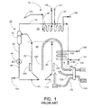
- FIG 1 illustrates the steam-water flow system and the gas flow system for a conventional once-through two pass Carolina-style boiler 10 with a furnace 20 capable of operating at subcritical to supercritical pressure.
- the boiler 10 includes fluid cooled membrane tube enclosure walls typically made up of water/steam conveying tubes 30 separated from one another by a steel membrane (not visible) to achieve a gas-tight enclosure.
- the tubes 30 are referred to herein as water tubes for brevity and simplicity.
- the steam generator operates with a variable pressure profile versus load (subcritical to supercritical pressure).
- the water enters the economizer through inlet 141 and absorbs heat, then travels from economizer outlet 142 to inlet 143 at the base of the furnace.
- a lower bottle (not shown) may be present to distribute this water.
- the water then travels up through the furnace wall tubes 30. As the water travels through these water tubes 30, the water cools the tubes exposed to high-temperature flue gas in the combustion chamber 60 and absorbs energy from the flue gas to become a steam-water mixture at subcritical pressure (and remains a single phase fluid if at supercritical pressure conditions).
- the fluid is discharged into the vertical steam separators 42, where the steam-water mixture is separated, when subcritical, into wet steam (i.e., saturated steam) and water. Any water can exit via downcomer 50 and pass from outlet 144 to the economizer inlet 141.
- the vertical separators act as conveying pipes with all the entering steam leaving from the top outlets.
- the steam is used to cool the flue gas in the convection pass path 70 of the furnace through steam tubes or roof tubes 75 leading from the vertical separator.
- the steam then passes from outlet 149 to inlet 145 and is fed through superheater heating surface 80, then sent to the high pressure steam turbine (reference number 146 ).
- Steam returning from the high pressure steam turbine passes through the reheater heating surface 90 to absorbing additional energy from the flue gas, and can then be sent to a second intermediate-pressure or low-pressure steam turbine (reference number 148 ).
- the steam sent to the turbines is generally dry steam (100% steam, no water).
- the steam from the superheater 80 heating surfaces can be sent to a high pressure (HP) turbine, then from the reheater 90 heating surface to the intermediate pressure (IP) and low pressure (LP) steam turbine stages (not shown).
- Feedwater conveyed through economizer 100 may also be used to absorb energy from the flue gas before the flue gas exits the boiler; the heated feedwater is then sent to the furnace enclosure tubes 30, or can be sent through superheater 80 and reheater 90.
- air for combustion can be supplied to the furnace 20 through several means.
- a fan 102 supplies air 104 to a regenerative air heater 106.
- the heated air is then sent as secondary air 108 to windboxes for distribution to individual burners and as primary air 110 to the coal pulverizer 112, where coal is dried and pulverized.
- the primary air (now carrying coal particles) 116 is then sent to the burners 120 and mixed with the secondary air 108 for combustion and formation of flue gas 130 in the combustion chamber 60.
- the flue gas flows upwardly through the furnace combustion chamber 60 and then follows the convection pass path 70 to flue gas exhaust 160 past superheater 80, reheater 90, and economizer 100.
- the flue gas can then be passed through the regenerative air heater 106 (to heat the incoming air 104 ) and pollution control equipment 114 and, if desired, recycled through the furnace 20.
- the flue gas exits the boiler 10 through the flue gas exhaust 160.
- Figure 1 also illustrates the start up equipment of the steam-water flow system.
- a vertical steam separator 42 is used instead of a conventional horizontal steam drum of a subcritical natural circulation boiler.
- a boiler circulation pump 44 and shut-off valve 46 are also present in the downcomer 50 to augment the flow in the furnace enclosure walls 30 and the economizer 100 during start-up.
- the boiler circulation pump is stopped at the load where 100% dry steam is entering the vertical steam separator from the furnace enclosure.
- the vertical steam separator remains in service and a static column of water remains in the downcomer 50.
- the steam outlet terminals of a Carolina style boiler are located at the top of the boiler, generally at a relatively high elevation from grade of about 200 feet.
- the steam is then carried to a steam turbine via steam leads (i.e. pipes).
- the steam leads are made from a nickel alloy for 700°C steam temperatures, which is very expensive. Due to the location of the steam outlet terminals at the top of the boiler, the length of the steam leads can be very great. It would be desirable to be able to reduce the length of the steam leads from the steam outlet terminals of the boiler to the steam turbine where the steam is used to generate electricity.
- the present disclosure relates to a boiler system which can be used in conjunction with a steam turbine to generate electricity.
- the steam outlet terminals of the boiler are located at the base of the boiler, instead of at the top of the boiler. This reduces the needed length of the steam leads, in turn reducing the cost and improving the economics of the overall system.
- a steam generator comprising: a downdraft furnace enclosure formed from walls made of water or steam cooled tubes, and wherein the furnace walls define a top end and a bottom gas outlet; a convection pass enclosure including a bottom gas inlet and horizontal tube banks located above the bottom gas inlet; a hopper tunnel connecting the bottom gas outlet of the downdraft furnace enclosure to the bottom gas inlet of the convection pass enclosure; and a steam outlet terminal located at the base of the steam generator.
- the bottom gas outlet of the downdraft furnace enclosure may include an outwardly-extending throat that extends into a porthole of the bottom gas inlet of the convection pass enclosure.
- the top end of the downdraft furnace enclosure may include a gas inlet for receiving flue gas from an associated furnace.
- the steam generator may further comprise a windbox and burners at the top end of the downdraft furnace enclosure for generating flue gas.
- the flue gas exiting the convection pass enclosure may be recirculated to the top end of the downdraft furnace enclosure, to a base of the downdraft furnace enclosure, and/or to a base of the convection pass enclosure.
- the flue gas exiting the convection pass enclosure may pass through a particulate cleaning device and then be recirculated to the top end of the downdraft furnace enclosure, a base of the downdraft furnace enclosure, or a base of the convection pass enclosure.
- the hopper tunnel may be lined with a refractory material.
- the hopper tunnel can include a submerged chain conveyor for removing ash and slag.
- the submerged chain conveyor may travel in-line with the flue gas flow, or may travel transverse to the flue gas flow.
- the hopper tunnel can be formed from steam or water-cooled tube panels. Water trough seals may be present between the downdraft furnace enclosure, the hopper tunnel, and the convection pass enclosure.
- the fluid in the tubes of the downdraft furnace enclosure can flow counter-current to flue gas flow.
- the convection pass enclosure is sometimes formed from enclosure walls made of steam or water cooled tubes, wherein the cooling fluid in the tubes of the convection pass enclosure flow co-current to flue gas flow.
- the horizontal tube banks in the convection pass enclosure may include superheaters, reheaters, and economizers.
- the steam generator may further comprise an upper horizontal pass enclosure connected to a top end of the convection pass enclosure and a down pass, the upper horizontal pass and the down pass containing additional tube banks.
- waterside refers to any area of the boiler that is exposed to water or steam.
- airside refers to an area of the boiler that is exposed to direct heat from the furnace, or in other words the combustion gas from the furnace.
- the terms “upper” and “lower” are relative to each other in location, i.e. an upper component is located at a higher elevation than a lower component in a given orientation.
- the terms “inlet” and “outlet” are relative to a fluid flowing through them with respect to a given structure, e.g. a fluid flows through the inlet into the structure and flows through the outlet out of the structure.
- upstream and downstream are relative to the direction in which a fluid flows through various components, i.e. the flow fluids through an upstream component prior to flowing through the downstream component.
- first vertical structure and a second vertical structure are not necessarily parallel to each other.
- top and bottom or base are used to refer to surfaces where the top is always higher than the bottom/base relative to an absolute reference, i.e. the surface of the earth.
- above and below are used to refer to the location of two structures relative to an absolute reference. For example, when the first component is located above a second component, this means the first component will always be higher than the second component relative to the surface of the earth.
- upwards” and “downwards” are also relative to an absolute reference; an upwards flow is always against the gravity of the earth.
- the term “supercritical” refers to a fluid that is at a temperature above its critical temperature or at a pressure above its critical pressure or both.
- the critical temperature of water is 374.15 °C
- the critical pressure of water is 3200.1 psia (22.1 MPa).
- a fluid at a temperature that is above its boiling point at a given pressure but is below its critical pressure is considered to be “superheated” but “subcritical”.
- a superheated fluid can be cooled (i.e. transfer energy) without changing its phase.
- wet steam refers to a saturated steam/water mixture (i.e., steam with less than 100% quality where quality is percent steam content by mass).
- dry steam refers to steam having a quality equal to greater than 100% (i.e., no liquid water is present).
- Supercritical water or steam will have no visible bubble interface or meniscus forming during a heating or cooling process due to zero surface tension on reaching the critical point temperature.
- the fluid continues to act like a single phase flow while converting from water to steam or steam to water, and is a non-equilibrium thermodynamic condition where rapid changes in density, viscosity and thermal conductivity can occur.
- the steam outlet terminals are at the top center of the structure.
- the top of the structure is relatively high, about 200 to 250 feet.
- Such a height is necessary for the furnace to have a volume sufficient for the coal particles to be completely combusted, for the water tubes to absorb the heat energy, and to lower the flue gas temperature below the ash fusion temperature (minimizing slagging and fouling in the various tube banks).
- the present disclosure relates to such a steam generator written.
- the steam generator of the present disclosure is an advanced ultra supercritical steam generator, which can produce an outlet steam pressure of 25 MPa (3625 psia) or higher, including 29 MPa (4200 psia) or higher; and an outlet steam temperature of 570°C (1058°F) or higher, including 730°C (1346°F) or higher.
- the advanced ultra supercritical once through steam generator of the present disclosure does not have fairly uniform enclosure wall temperatures near saturation.
- the conventional once through supercritical steam generator must be carefully designed to have fairly narrow differences and very similar geometry, thermo hydraulic flow characteristics and heat absorption conditions on all of the welded enclosure wall tubes. The present design thus permits the joining of a series of separate enclosures along the gas flow path which can operate at different material temperatures.
- FIG. 2 is a side perspective view of a first example embodiment of a steam generator 200 of the present disclosure.
- the steam generator generally includes three structures: a downdraft furnace enclosure 210, a hopper tunnel 270, and a convection pass enclosure 230.
- the downdraft furnace enclosure is shown here on the left.
- the downdraft furnace enclosure 210 is formed from walls 216 made of water or steam cooled tubes, which may be arranged vertically or spirally.
- the furnace enclosure walls 216 define a top end 212 and a bottom end 214. The top end and the bottom end are at opposite ends of the furnace walls.
- a windbox 218 and burners 220 are located near the top end of the furnace.
- the burners may be arranged in the roof (i.e. the top end) or at the top of the furnace walls. Burners may be located on all four walls, opposed on two of the walls, or near the corners of the four walls.
- air and coal are fed into the top end 212 by the windbox or roof vestibule 218, and combusted using the burners 220 to generate hot flue gas 202.
- Oxy-combustion i.e. using oxygen-enriched recirculated gas
- the windbox also generates an air flow that causes the flue gas to flow downwards due to mechanical draft fans (rather than rising as would naturally occur; the downdraft is aided by the wall cooling the flue gas).
- a bottom gas outlet 222 is present at the bottom end 214, through which the hot flue gas exits the furnace enclosure 210.
- the flue gas flows through a hopper tunnel 270 located at the base of the furnace enclosure.
- the hopper tunnel 270 fluidly connects the bottom gas outlet 222 of the downdraft furnace enclosure with a bottom gas inlet 236 of the convection pass enclosure.
- the hopper tunnel also flexibly seals the bottom gas outlet and the bottom gas inlet.
- the flue gas may have a temperature of about 500°F to about 2500°F.
- the flue gas 202 then flows upwards through the convection pass enclosure 230 past horizontally arranged tube banks that act as superheater 240, reheater 242, and/or economizer 244 surfaces. These surfaces capture additional energy from the flue gas.
- the flue gas may have a temperature of about 240°F to about 825°F.
- the convection pass enclosure 230 itself also has a top end 232 and a bottom end 234 .
- the flue gas may pass through a regenerative air heater to transfer some of the remaining heat energy to incoming air.
- the flue gas may also be sent to pollution control units to remove undesired byproducts.
- the flue gas can pass through a selective catalytic reduction (SCR) unit to remove NOx, a flue gas desulfurization (FGD) unit to remove SOx, and/or a particulate cleaning device (e.g. a baghouse or electrostatic precipitator).
- SCR selective catalytic reduction
- FGD flue gas desulfurization
- a particulate cleaning device e.g. a baghouse or electrostatic precipitator.
- the pollution control units and the regenerative air heater are placed in an order suitable for optimum pollution reduction.
- the SCR unit is placed upstream of the regenerative air heater.
- the flue gas exiting the convection pass enclosure may be recirculated to the windbox or vestibule 218 at the top of the furnace enclosure, a practice generally referred to as gas recirculation.
- the flue gas exiting the convection pass enclosure can also be recirculated to the base 252 of the downdraft furnace enclosure for steam temperature control and/or to the base 254 of the convection pass enclosure and used to control the flue gas temperature, which is generally referred to as gas tempering.
- the steam generator may include any of these recirculation paths, or may include all three recirculation paths.
- relatively cold water from the economizer outlet enters the steam generator at the base of the furnace walls 216, and flows through the water tubes, becoming a steam/water mixture by absorbing the heat energy in the flue gas.
- This water flows counter-current to the flue gas flow (i.e. the water flows upwards while the flue gas flows downwards).
- the steam/water mixture is collected in outlet headers and sent to vertical steam separators 260 and separated into wet steam and water.
- the steam is sent to the convection pass enclosure 230 through the superheater 240 then to the steam turbine, and then returns from the steam turbine to pass through the reheater 242 tube banks in the convection pass enclosure.
- the convection pass enclosure is also formed from enclosure walls made of water or steam cooled tubes, which can also capture energy.
- the fluid flow in the enclosure walls of the convection pass enclosure is co-current to the flue gas flow (i.e. both flow upwards).
- the downdraft furnace enclosure is water-cooled at lower loads and becomes steam cooled near the outlet at higher loads, while the convection pass enclosure is steam-cooled.
- the supercritical steam and/or reheat steam exits at one or more steam outlet terminals located at the base 264 of the convection pass enclosure, which is part of the steam generator.
- the reheat steam outlet terminal is labeled with reference numeral 261, while the supercritical steam outlet terminal is labeled with reference number 262, and either or both of these outlet terminals may be present.
- the term "base” refers here to the bottom one-third of the steam generator's height. For example, if the steam generator has a height of about 60 feet, then the steam outlet terminal(s) is at a height of at about 20 feet. It should be recognized that the furnace enclosure and the convection pass enclosure may be of different heights.
- the steam leads for main steam and hot reheat piping needed to operate an advanced ultra supercritical steam generator at 700°C (1292°F) are as much as four (4) times the cost of material by mass for the steam leads needed to operate a steam generator at 600°C (1112°F). It can thus be advantageous to use the present design to lower the steam outlet terminal rather than incur the cost of such piping.
- the tube banks in the convection pass enclosure should be drainable. Internal deposits are generally dispersed along the tube rows, so as not to concentrate in the lower bends of pendant sections. At the connection to the enclosure walls, expansion water seals or gas tight expansion joints (not shown) are present between the enclosure walls and the tube banks.
- the hopper tunnel 270 flexibly connects the downdraft furnace enclosure 210 to the convection pass enclosure 230.
- the hopper tunnel is desirably adiabatic.
- the hopper tunnel 270 includes one or more ash and slag outlets connected to submerged chain conveyor(s) 274. It is contemplated that ash and slag fall into the submerged chain conveyor(s) and are disposed of.
- the chain conveyor can either be in-line with the flue gas flow, or can be transverse to the flue gas flow. As illustrated here, the chain conveyor is in-line.
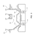
- FIG 3 is an alternative embodiment of the hopper tunnel 270, in which the chain conveyors are transverse to the flue gas flow 202.
- Two submerged chain conveyors 474 are visible in the hopper tunnel 270 under the downdraft furnace enclosure 210 and the convection pass enclosure 230.
- the base 412 of the downdraft furnace enclosure and the base 432 of the convection pass enclosure are sloped to guide the ash/slag into the submerged chain conveyors.
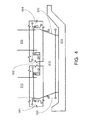
- FIG 4 is another embodiment of the hopper tunnel.
- the hopper tunnel is also formed from steam or water-cooled tube panels.
- the tube panels 500 forming the sides of the hopper tunnel are bottom-supported, while the roof 502 of the hopper tunnel is top-supported using the side walls of the hopper tunnel.
- Water trough seals or nonmetallic seals 504 can be made between the hopper tunnel 270, the downdraft furnace enclosure 210, and the convection pass enclosure 230.
- the chain conveyor 274 is illustrated as forming the closure of the hopper tunnel.
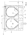
- FIGS 5-7 are various views illustrating another possible variation on the structure of the hopper tunnel 270.
- the downdraft furnace enclosure 210 is on the left, and the convection pass enclosure 230 is on the right.
- the bottom of the hopper tunnel contains two submerged chain conveyors 474.
- the base 412 of the downdraft furnace enclosure is sloped to guide the ash/slag into the conveyors.
- a vertical wall 292 is located in the hopper tunnel between the two conveyors.
- the base 294 of the vertical wall is sloped laterally in both directions to guide the ash/slag into the conveyors.
- Arches 296 are present in the center of the hopper tunnel, and can be used to support the top tube panels 502 of the hopper tunnel.
- the vertical wall may have any desired length.
- Water trough seals 504 between the hopper tunnel, the downdraft furnace enclosure, and the convection pass enclosure are also visible. It is contemplated that ground level would be at the level of the water trough seals.
- the tunnel itself can be out of concrete, refractory, and dirt. Water cooling tube circuits can be placed in the walls and/or arches of the tunnel.
- the base 294 of the vertical walls are sloped to create a funnel for the ash/slag, with the resulting opening 480 having a width 482 that is less than the width 484 of the submerged chain conveyor 486 .
- the maintenance position for the conveyor is depicted here 488. It is contemplated that as needed for maintenance or other purposes, the conveyors can be switched out.
- the hopper tunnel 270 must be able to handle the transfer of very hot flue gas.
- the hopper tunnel may be lined with a refractory material 276, which is chemically and physically stable at high temperatures.
- suitable refractory materials include refractory brick containing aluminum oxide, silica, or magnesium oxide, or ceramic tiles. Such materials can withstand temperatures of 2800°F to 3000°F.
- the hopper tunnel has a width 282, refractory brick 276 located around the entire periphery of the tunnel, and insulation 278 surrounding the brick, and having the appropriate dimensions.
- the upper portion of the hopper tunnel has a height 284, and the lower portion of the hopper tunnel has a height 286.
- a mechanical transport system 280 e.g. a submerged chain conveyor that moves the ash out of the hopper tunnel.
- Figure 8 is a side view of an embodiment of the downdraft inverted tower steam generator and steam turbine.
- the downdraft furnace enclosure 1010 is on the left, and the convection pass enclosure 1030 is on the right.
- the steam turbine 1100 is on the far right.
- the solid lines 1122 represent the steam leads that carry the supercritical steam and/or reheat steam to the steam turbine.
- the dotted rectangles 1128 represent reheaters / superheaters.
- the rectangles 1156 represent economizers.
- the rectangle 1134 represents a separate low pressure steam generator to produce auxiliary steam for utility purposes.
- the hopper tunnel 270 is also shown here. Again, the base 412 is sloped longitudinally to direct ash/slag into the conveyors 474.
- FIGS 9-12 are various drawings showing another embodiment of a steam generator.
- This embodiment contains the downdraft furnace enclosure 1010, hopper tunnel 1070, and convection pass enclosure 1030, and also contains additional down pass 1092.
- Figure 9 is a perspective view of the exterior of the steam generator.
- the downdraft furnace enclosure 1010 is on the far left, and the convection pass enclosure 1030 is in the center.
- the hopper tunnel 1070 is the triangular structure linking the base of the convection pass enclosure 1030 with the base of the downdraft furnace enclosure 1010.
- the down pass 1092 is the structure on the far right.
- the rectangle at the bottom of the hopper tunnel represents the chain conveyor 1074 that removes ash/slag.
- the solid lines 1122 represent the steam outlet piping.
- the circles 1126 represent burner openings at the top of the downdraft furnace enclosure.
- Reference numeral 1120 is the structure connecting the convection pass enclosure 1030 with the down pass 1092 .
- Figure 10 is a side view (along an imaginary ⁇ -axis) of the steam generator and the steam turbine.
- the dotted rectangles 1128 represent the horizontal tube banks that serve as reheaters / superheaters, and provide the outlet steam terminals near the base of the steam generator/convection pass enclosure.
- the dashed lines 1122 represent the steam leads that carry the supercritical steam and/or reheat steam to the steam turbine.
- the steam turbine 1100 is contained in a building marked by reference numeral 1130 . It should be noted that the steam turbine is located on elevation 1132, relative to the steam generator.
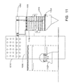
- Figure 11 is a front view (along an imaginary x-axis) of the steam generator and the steam turbine.
- the convection pass enclosure 1030 is not fully visible here, because it is behind the building containing the steam turbine.
- the additional down pass 1092 is seen on the right.
- the dotted rectangles 1128 represent the reheaters / superheaters.
- the stippled rectangles 1156 represent horizontal tube banks that serve as economizers.
- the solid black rectangle 1134 represents a separate low pressure steam generator to produce auxiliary steam for utility purposes such as sootblowing. Using a lower temperature coolant helps reduce flue gas temperature and does not use super-elevated high temperature high pressure steam for lower level services.
- the striped rectangle 1136 represents a space for future heating surfaces to be installed (e.g. for modifications during the service life of the steam generator).
- the steam turbine is marked as reference numeral 1100 .
- Figure 12 is a plan view (i.e. from the top) of the steam generator 1000 and steam turbine 1100 .
- the lines 1122 illustrate the steam leads that feed the steam turbine.
- the steam leads run from the steam outlet terminals 1062 on the convection pass enclosure 1030 to multiple locations on the steam turbine.
- Figure 13 is a side view (along an imaginary x-axis) of another embodiment of a modified tower steam generator and the steam turbine.
- the dotted rectangles 1128 represent reheaters / superheaters.
- the stippled rectangles 1156 represent economizers.
- the solid black rectangle 1134 represents a separate low pressure steam generator to produce auxiliary steam for utility purposes.
- the striped rectangle 1136 represents future heating surfaces.
- the secondary air duct 1140 leading from the regenerative air heater 1142 is also shown here.
- the dashed lines 1122 are the steam leads that feed the steam turbine 1100 with supercritical steam and/or reheat steam.
- the solid lines 1148 are feedwater and cold reheat steam lines from the feedwater heaters and the steam turbine.
- Figure 14 is a plan view (i.e. from the top) showing additional details of the modified tower steam generator.
- the lines 1158 in the middle represent convection heating surface.
- the two circles 1144 on the right-hand side represent regenerative air heaters.
- the nine hexagonal shaped structures 1152 represent coal pulverizers.
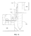
- Figure 15 is a side view (along an imaginary x-axis) of the modified tower steam generator having a base elevation difference compared to the steam turbine 1100 , which reduces steam line length.
- the structure 1154 in the center represents the furnace enclosure.
- the convection pass enclosure 1155 is above the furnace enclosure.
- the rectangle 1156 on the right represents the additional down pass downstream of the convection pass enclosure.
- the lines 1122 are the steam leads that feed the steam turbine 1100 with supercritical steam and/or reheat steam.
- the black lines 1148 are feedwater and cold reheat steam lines from the feedwater heaters and steam turbine. It should be noted that the black lines are run from the steam turbine to the horizontal convection pass enclosure, which is not completely visible here. Again, please note that the steam turbine is located on elevation 1132.
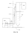
- Figure 16 is similar to Figure 15 , except the steam turbine 1100 is located at the same elevation 1133 as the steam generator.
- convection pass enclosure is depicted in the various Figures as having a single gas path. It is also contemplated that the convection pass enclosure can include parallel gas paths, where one gas path can be used for steam temperature control using gas biasing.
- FIG 17 is a side view showing another embodiment of the downdraft inverted tower steam generator.
- This embodiment also includes a downdraft furnace enclosure 1010, a convection pass enclosure 1030, and a hopper tunnel 1070.
- a bottom gas outlet is present at the bottom end of the downdraft furnace enclosure, and a bottom gas inlet is present at the bottom end of the convection pass enclosure.
- the upper portion of the hopper tunnel is formed by the bottom ends of the downdraft furnace enclosure 1010 and the convection pass enclosure 1030 .
- the bottom gas outlet 1022 of the downdraft furnace enclosure 1010 includes an outwardly extending nozzle that constricts in diameter as it extends from the walls 1016 of the flue tunnel to form a throat 1026 .
- the bottom gas inlet 1036 of the convection pass enclosure 1030 includes an inward-facing porthole 1038 . It is contemplated that the throat 1026 of the bottom gas outlet extends into the porthole 1038 of the bottom gas inlet to form a passageway through which the flue gas (arrow 1002 ) can flow from the downdraft furnace enclosure into the convection pass enclosure. It should be noted that the walls of the flue tunnel ( 1016 ) and the convection pass enclosure ( 1035 ) are not welded together. However, the flat vertical faces of the two enclosures are placed closely together to permit the use of flexible gas-tight sealing toggle connections. In addition, stanchion bracing (not shown) may be used to control the relative movement of the two enclosures that may occur.
- the downdraft furnace enclosure 1010 and the convection pass enclosure 1030 include an opening into the lower portion of the hopper tunnel, where the submerged chain conveyor 274 is located.
- the various banks (reheat, superheat, economizer) in the convection pass enclosure 1030 are not illustrated here.
- a supercritical steam generator that includes a downdraft furnace enclosure, a hopper tunnel, and a convection pass enclosure, with the hopper tunnel joining the downdraft furnace enclosure and convection pass enclosure together. Flue gas passes down through the downdraft furnace enclosure through the hopper tunnel and up through the convection pass enclosure.
- This structure permits the outlet steam terminals, which provide access to the resultant supercritical steam and/or reheat steam, to be located at a base of the steam generator rather than at the top of the steam generator as with conventional boilers. This reduces the length of the steam leads from the steam generator to a steam turbine that produces electricity using the supercritical steam.
Abstract
Description
- The present disclosure relates to steam generating systems which can be used in combination with carbon capture sequestration (CCS) technology for use in coal-fired power generation.
- During combustion, the chemical energy in a fuel is converted to thermal heat inside the furnace of a boiler. The thermal heat is captured through heat-absorbing surfaces in the boiler to produce steam. The fuels used in the furnace include a wide range of solid, liquid, and gaseous substances, including coal, natural gas, and diesel oil. Combustion transforms the fuel into a large number of chemical compounds. Water and carbon dioxide (CO2) are the products of complete combustion. Incomplete combustion reactions may result in undesirable byproducts that can include particulates (e.g. fly ash, slag), acid gases such as SOx or NOx, metals such as mercury or arsenic, carbon monoxide (CO), and hydrocarbons (HC).
-
Figure 1 illustrates the steam-water flow system and the gas flow system for a conventional once-through two pass Carolina-style boiler 10 with afurnace 20 capable of operating at subcritical to supercritical pressure. As is known, theboiler 10 includes fluid cooled membrane tube enclosure walls typically made up of water/steam conveying tubes 30 separated from one another by a steel membrane (not visible) to achieve a gas-tight enclosure. Thetubes 30 are referred to herein as water tubes for brevity and simplicity. - The steam generator operates with a variable pressure profile versus load (subcritical to supercritical pressure). The water enters the economizer through
inlet 141 and absorbs heat, then travels fromeconomizer outlet 142 toinlet 143 at the base of the furnace. A lower bottle (not shown) may be present to distribute this water. The water then travels up through thefurnace wall tubes 30. As the water travels through thesewater tubes 30, the water cools the tubes exposed to high-temperature flue gas in thecombustion chamber 60 and absorbs energy from the flue gas to become a steam-water mixture at subcritical pressure (and remains a single phase fluid if at supercritical pressure conditions). The fluid is discharged into thevertical steam separators 42, where the steam-water mixture is separated, when subcritical, into wet steam (i.e., saturated steam) and water. Any water can exit viadowncomer 50 and pass fromoutlet 144 to theeconomizer inlet 141. When the fluid is supercritical, the vertical separators act as conveying pipes with all the entering steam leaving from the top outlets. The steam is used to cool the flue gas in theconvection pass path 70 of the furnace through steam tubes orroof tubes 75 leading from the vertical separator. The steam then passes fromoutlet 149 toinlet 145 and is fed throughsuperheater heating surface 80, then sent to the high pressure steam turbine (reference number 146). Steam returning from the high pressure steam turbine (reference number 147) passes through thereheater heating surface 90 to absorbing additional energy from the flue gas, and can then be sent to a second intermediate-pressure or low-pressure steam turbine (reference number 148). The steam sent to the turbines is generally dry steam (100% steam, no water). The steam from thesuperheater 80 heating surfaces can be sent to a high pressure (HP) turbine, then from thereheater 90 heating surface to the intermediate pressure (IP) and low pressure (LP) steam turbine stages (not shown). Feedwater conveyed througheconomizer 100 may also be used to absorb energy from the flue gas before the flue gas exits the boiler; the heated feedwater is then sent to thefurnace enclosure tubes 30, or can be sent throughsuperheater 80 andreheater 90. - Referring to the gas flow system, air for combustion can be supplied to the
furnace 20 through several means. Typically, afan 102 suppliesair 104 to aregenerative air heater 106. The heated air is then sent assecondary air 108 to windboxes for distribution to individual burners and asprimary air 110 to thecoal pulverizer 112, where coal is dried and pulverized. The primary air (now carrying coal particles) 116 is then sent to theburners 120 and mixed with thesecondary air 108 for combustion and formation offlue gas 130 in thecombustion chamber 60. The flue gas flows upwardly through thefurnace combustion chamber 60 and then follows theconvection pass path 70 toflue gas exhaust 160 pastsuperheater 80,reheater 90, andeconomizer 100. The flue gas can then be passed through the regenerative air heater 106 (to heat the incoming air 104) andpollution control equipment 114 and, if desired, recycled through thefurnace 20. The flue gas exits theboiler 10 through theflue gas exhaust 160. -
Figure 1 also illustrates the start up equipment of the steam-water flow system. When the steam is supercritical, avertical steam separator 42 is used instead of a conventional horizontal steam drum of a subcritical natural circulation boiler. Aboiler circulation pump 44 and shut-offvalve 46 are also present in thedowncomer 50 to augment the flow in thefurnace enclosure walls 30 and theeconomizer 100 during start-up. The boiler circulation pump is stopped at the load where 100% dry steam is entering the vertical steam separator from the furnace enclosure. The vertical steam separator remains in service and a static column of water remains in thedowncomer 50. - As illustrated here, the steam outlet terminals of a Carolina style boiler are located at the top of the boiler, generally at a relatively high elevation from grade of about 200 feet. The steam is then carried to a steam turbine via steam leads (i.e. pipes). The steam leads are made from a nickel alloy for 700°C steam temperatures, which is very expensive. Due to the location of the steam outlet terminals at the top of the boiler, the length of the steam leads can be very great. It would be desirable to be able to reduce the length of the steam leads from the steam outlet terminals of the boiler to the steam turbine where the steam is used to generate electricity.
- Particular aspects and embodiments are set out in the appended independent and dependent claims.
- The present disclosure relates to a boiler system which can be used in conjunction with a steam turbine to generate electricity. The steam outlet terminals of the boiler are located at the base of the boiler, instead of at the top of the boiler. This reduces the needed length of the steam leads, in turn reducing the cost and improving the economics of the overall system.
- Disclosed in various embodiments herein is a steam generator, comprising: a downdraft furnace enclosure formed from walls made of water or steam cooled tubes, and wherein the furnace walls define a top end and a bottom gas outlet; a convection pass enclosure including a bottom gas inlet and horizontal tube banks located above the bottom gas inlet; a hopper tunnel connecting the bottom gas outlet of the downdraft furnace enclosure to the bottom gas inlet of the convection pass enclosure; and a steam outlet terminal located at the base of the steam generator.
- The bottom gas outlet of the downdraft furnace enclosure may include an outwardly-extending throat that extends into a porthole of the bottom gas inlet of the convection pass enclosure.
- The top end of the downdraft furnace enclosure may include a gas inlet for receiving flue gas from an associated furnace.
- The steam generator may further comprise a windbox and burners at the top end of the downdraft furnace enclosure for generating flue gas.
- The flue gas exiting the convection pass enclosure may be recirculated to the top end of the downdraft furnace enclosure, to a base of the downdraft furnace enclosure, and/or to a base of the convection pass enclosure.
- The flue gas exiting the convection pass enclosure may pass through a particulate cleaning device and then be recirculated to the top end of the downdraft furnace enclosure, a base of the downdraft furnace enclosure, or a base of the convection pass enclosure.
- The hopper tunnel may be lined with a refractory material. The hopper tunnel can include a submerged chain conveyor for removing ash and slag. The submerged chain conveyor may travel in-line with the flue gas flow, or may travel transverse to the flue gas flow.
- Alternatively, the hopper tunnel can be formed from steam or water-cooled tube panels. Water trough seals may be present between the downdraft furnace enclosure, the hopper tunnel, and the convection pass enclosure.
- The fluid in the tubes of the downdraft furnace enclosure can flow counter-current to flue gas flow.
- The convection pass enclosure is sometimes formed from enclosure walls made of steam or water cooled tubes, wherein the cooling fluid in the tubes of the convection pass enclosure flow co-current to flue gas flow.
- The horizontal tube banks in the convection pass enclosure may include superheaters, reheaters, and economizers.
- The steam generator may further comprise an upper horizontal pass enclosure connected to a top end of the convection pass enclosure and a down pass, the upper horizontal pass and the down pass containing additional tube banks.
- These and other non-limiting characteristics are more particularly described below.
- The following is a brief description of the drawings, which are presented for the purposes of illustrating the example embodiments disclosed herein and not for the purposes of limiting the same.
-
Figure 1 is a schematic diagram illustrating a conventional two-pass (Babcock and Wilcox Carolina-style) subcritical or supercritical once through type steam generator -
Figure 2 is a side perspective view of a first example embodiment of a once through steam generator of the present disclosure, wherein the inverted tower downdraft furnace enclosure includes the burners that generate the flue gas. -
Figure 3 is a cross-sectional view of one possible design for the hopper tunnel, with conveyors traveling transverse to the flue gas flow. The hopper tunnel is an in-ground refractory lined, concrete and steel arch way to transfer the flue gas flow. -
Figure 4 is another embodiment of the hopper tunnel, being formed from steam or water-cooled tube panels. -
Figure 5 is a perspective view showing a variation of the hopper tunnel having a vertical wall. -
Figure 6 is a front view of the hopper tunnel ofFigure 5 . -
Figure 7 is a side view of the hopper tunnel ofFigure 5 . -
Figure 8 is a side view of another example embodiment of a downdraft inverted tower steam generator of the present disclosure, showing the steam turbine in relation to the steam generator. -
Figure 9 is a perspective view of another embodiment of a downdraft inverted tower steam generator and the steam turbine piping. -
Figure 10 is a side view (along an imaginary γ-axis) of the steam generator ofFigure 9 . -
Figure 11 is a front view (along an imaginary x-axis) of the steam generator ofFigure 9 . -
Figure 12 is a plan view (i.e. from the top) of the steam generator ofFigure 9 . -
Figure 13 is a side view showing the steam turbine at the same grade as the modified tower steam generator (i.e. in the conventionally expected relative position). -
Figure 14 is a plan view (i.e. from the top) showing additional details of the modified tower steam generator ofFigure 13 . -
Figure 15 is a side view of an embodiment where the modified tower steam generator has a base elevation difference compared to the steam turbine. -
Figure 16 is a side view of an embodiment where the modified tower steam generator has the same base elevation as the steam turbine. -
Figure 17 is a side view of another example embodiment of a steam generator of the present disclosure, wherein the bottom gas outlet of the downdraft furnace enclosure is shaped as a throat that enters a porthole of the bottom gas inlet of the convection pass enclosure. - A more complete understanding of the components, processes, and apparatuses disclosed herein can be obtained by reference to the accompanying drawings. These figures are merely schematic representations based on convenience and the ease of demonstrating the present disclosure, and are, therefore, not intended to indicate relative size and dimensions of the devices or components thereof and/or to define or limit the scope of the described embodiments.
- Although specific terms are used in the following description for the sake of clarity, these terms are intended to refer only to the particular structure of the embodiments selected for illustration in the drawings, and are not intended to define or limit the scope of the disclosure. In the drawings and the following description below, it is to be understood that like numeric designations refer to components of like function.
- The singular forms "a," "an," and "the" include plural referents unless the context clearly dictates otherwise.
- As used in the specification and in the claims, the term "comprising" may include the embodiments "consisting of" and "consisting essentially of."
- Numerical values should be understood to include numerical values which are the same when reduced to the same number of significant figures and numerical values which differ from the stated value by less than the experimental error of conventional measurement technique of the type described in the present application to determine the value.
- All ranges disclosed herein are inclusive of the recited endpoint and independently combinable (for example, the range of "from 2 watts to 10 watts" is inclusive of the endpoints, 2 watts and 10 watts, and all the intermediate values).
- As used herein, approximating language may be applied to modify any quantitative representation that may vary without resulting in a change in the basic function to which it is related. Accordingly, a value modified by a term or terms, such as "about" and "substantially," may not be limited to the precise value specified, in some cases. The modifier "about" should also be considered as disclosing the range defined by the absolute values of the two endpoints. For example, the expression "from about 2 to about 4" also discloses the range "from 2 to 4."
- The terms "waterside", "water cooled", "steam cooled" or "fluid side" refer to any area of the boiler that is exposed to water or steam. In contrast, the terms "airside", "gas side" or "fireside" refer to an area of the boiler that is exposed to direct heat from the furnace, or in other words the combustion gas from the furnace. Where the specification refers to water and/or steam, the liquid and/or gaseous states of other fluids may also be used in the methods of the present disclosure.
- It should be noted that many of the terms used herein are relative terms. For example, the terms "upper" and "lower" are relative to each other in location, i.e. an upper component is located at a higher elevation than a lower component in a given orientation. The terms "inlet" and "outlet" are relative to a fluid flowing through them with respect to a given structure, e.g. a fluid flows through the inlet into the structure and flows through the outlet out of the structure. The terms "upstream" and "downstream" are relative to the direction in which a fluid flows through various components, i.e. the flow fluids through an upstream component prior to flowing through the downstream component.
- The terms "horizontal" and "vertical" are used to indicate direction relative to an absolute reference, i.e. ground level. However, these terms should not be construed to require structures to be absolutely parallel or absolutely perpendicular to each other. For example, a first vertical structure and a second vertical structure are not necessarily parallel to each other. The terms "top" and "bottom" or "base" are used to refer to surfaces where the top is always higher than the bottom/base relative to an absolute reference, i.e. the surface of the earth. The terms "above" and "below" are used to refer to the location of two structures relative to an absolute reference. For example, when the first component is located above a second component, this means the first component will always be higher than the second component relative to the surface of the earth. The terms "upwards" and "downwards" are also relative to an absolute reference; an upwards flow is always against the gravity of the earth.
- As used herein, the term "supercritical" refers to a fluid that is at a temperature above its critical temperature or at a pressure above its critical pressure or both. For example, the critical temperature of water is 374.15 °C, and the critical pressure of water is 3200.1 psia (22.1 MPa). A fluid at a temperature that is above its boiling point at a given pressure but is below its critical pressure is considered to be "superheated" but "subcritical". A superheated fluid can be cooled (i.e. transfer energy) without changing its phase. As used herein, the term "wet steam" refers to a saturated steam/water mixture (i.e., steam with less than 100% quality where quality is percent steam content by mass). As used herein, the term "dry steam" refers to steam having a quality equal to greater than 100% (i.e., no liquid water is present). Supercritical water or steam will have no visible bubble interface or meniscus forming during a heating or cooling process due to zero surface tension on reaching the critical point temperature. The fluid continues to act like a single phase flow while converting from water to steam or steam to water, and is a non-equilibrium thermodynamic condition where rapid changes in density, viscosity and thermal conductivity can occur.
- To the extent that explanations of certain terminology or principles of the solar receiver, boiler and/or steam generator arts may be necessary to understand the present disclosure, the reader is referred to Steam/its generation and use, 40th Edition, Stultz and Kitto, Eds., Copyright 1992, The Babcock & Wilcox Company, and to Steam/its generation and use, 41st Edition, Kitto and Stultz, Eds., Copyright 2005, The Babcock & Wilcox Company, the texts of which are hereby incorporated by reference as though fully set forth herein.
- In the conventional boiler of
Figure 1 , the steam outlet terminals are at the top center of the structure. The top of the structure is relatively high, about 200 to 250 feet. Such a height is necessary for the furnace to have a volume sufficient for the coal particles to be completely combusted, for the water tubes to absorb the heat energy, and to lower the flue gas temperature below the ash fusion temperature (minimizing slagging and fouling in the various tube banks). It is desirable to also lower the height of the steam outlet terminals, so as to bring them closer to the steam turbine and offer a shorter overall setting height. The present disclosure relates to such a steam generator written. In particular, the steam generator of the present disclosure is an advanced ultra supercritical steam generator, which can produce an outlet steam pressure of 25 MPa (3625 psia) or higher, including 29 MPa (4200 psia) or higher; and an outlet steam temperature of 570°C (1058°F) or higher, including 730°C (1346°F) or higher. Unlike the natural circulation drum boiler where the furnace enclosure walls operate at nearly uniform temperatures close to saturation temperature, the advanced ultra supercritical once through steam generator of the present disclosure does not have fairly uniform enclosure wall temperatures near saturation. The conventional once through supercritical steam generator must be carefully designed to have fairly narrow differences and very similar geometry, thermo hydraulic flow characteristics and heat absorption conditions on all of the welded enclosure wall tubes. The present design thus permits the joining of a series of separate enclosures along the gas flow path which can operate at different material temperatures. - In the Carolina (two-pass) boiler of
Figure 1 , the flue gas flows upwards, then horizontally and downwards through the tube banks. In the steam generators of the present disclosure, this gas flow path is reversed. The flue gas first flows downwards, then horizontally and then upwards through tube banks that convert the water to superheated or supercritical steam. This arrangement allows the steam terminals to be lower (closer to the ground) and closer to the steam turbine. -
Figure 2 is a side perspective view of a first example embodiment of asteam generator 200 of the present disclosure. The steam generator generally includes three structures: adowndraft furnace enclosure 210, ahopper tunnel 270, and aconvection pass enclosure 230. The downdraft furnace enclosure is shown here on the left. Thedowndraft furnace enclosure 210 is formed fromwalls 216 made of water or steam cooled tubes, which may be arranged vertically or spirally. Thefurnace enclosure walls 216 define atop end 212 and abottom end 214. The top end and the bottom end are at opposite ends of the furnace walls. As illustrated here, awindbox 218 andburners 220 are located near the top end of the furnace. The burners may be arranged in the roof (i.e. the top end) or at the top of the furnace walls. Burners may be located on all four walls, opposed on two of the walls, or near the corners of the four walls. - In use, air and coal are fed into the
top end 212 by the windbox orroof vestibule 218, and combusted using theburners 220 to generatehot flue gas 202. Oxy-combustion (i.e. using oxygen-enriched recirculated gas) or air firing can be used. The windbox also generates an air flow that causes the flue gas to flow downwards due to mechanical draft fans (rather than rising as would naturally occur; the downdraft is aided by the wall cooling the flue gas). Abottom gas outlet 222 is present at thebottom end 214, through which the hot flue gas exits thefurnace enclosure 210. The flue gas flows through ahopper tunnel 270 located at the base of the furnace enclosure. Thehopper tunnel 270 fluidly connects thebottom gas outlet 222 of the downdraft furnace enclosure with abottom gas inlet 236 of the convection pass enclosure. The hopper tunnel also flexibly seals the bottom gas outlet and the bottom gas inlet. When exiting the downdraft furnace enclosure, the flue gas may have a temperature of about 500°F to about 2500°F. Theflue gas 202 then flows upwards through theconvection pass enclosure 230 past horizontally arranged tube banks that act assuperheater 240,reheater 242, and/oreconomizer 244 surfaces. These surfaces capture additional energy from the flue gas. When exiting the convection pass enclosure, the flue gas may have a temperature of about 240°F to about 825°F. Theconvection pass enclosure 230 itself also has atop end 232 and abottom end 234. - The flue gas may pass through a regenerative air heater to transfer some of the remaining heat energy to incoming air. The flue gas may also be sent to pollution control units to remove undesired byproducts. For example, the flue gas can pass through a selective catalytic reduction (SCR) unit to remove NOx, a flue gas desulfurization (FGD) unit to remove SOx, and/or a particulate cleaning device (e.g. a baghouse or electrostatic precipitator). The pollution control units and the regenerative air heater are placed in an order suitable for optimum pollution reduction. For example, in specific embodiments, the SCR unit is placed upstream of the regenerative air heater. If desired, the flue gas exiting the convection pass enclosure may be recirculated to the windbox or
vestibule 218 at the top of the furnace enclosure, a practice generally referred to as gas recirculation. If desired, the flue gas exiting the convection pass enclosure can also be recirculated to thebase 252 of the downdraft furnace enclosure for steam temperature control and/or to thebase 254 of the convection pass enclosure and used to control the flue gas temperature, which is generally referred to as gas tempering. The steam generator may include any of these recirculation paths, or may include all three recirculation paths. - With regard to the fluid flow in the downdraft furnace enclosure, relatively cold water from the economizer outlet enters the steam generator at the base of the
furnace walls 216, and flows through the water tubes, becoming a steam/water mixture by absorbing the heat energy in the flue gas. This water flows counter-current to the flue gas flow (i.e. the water flows upwards while the flue gas flows downwards). The steam/water mixture is collected in outlet headers and sent tovertical steam separators 260 and separated into wet steam and water. The steam is sent to theconvection pass enclosure 230 through thesuperheater 240 then to the steam turbine, and then returns from the steam turbine to pass through thereheater 242 tube banks in the convection pass enclosure. In some embodiments, the convection pass enclosure is also formed from enclosure walls made of water or steam cooled tubes, which can also capture energy. In such embodiments, the fluid flow in the enclosure walls of the convection pass enclosure is co-current to the flue gas flow (i.e. both flow upwards). Generally, the downdraft furnace enclosure is water-cooled at lower loads and becomes steam cooled near the outlet at higher loads, while the convection pass enclosure is steam-cooled. - The supercritical steam and/or reheat steam exits at one or more steam outlet terminals located at the
base 264 of the convection pass enclosure, which is part of the steam generator. The reheat steam outlet terminal is labeled withreference numeral 261, while the supercritical steam outlet terminal is labeled withreference number 262, and either or both of these outlet terminals may be present. The term "base" refers here to the bottom one-third of the steam generator's height. For example, if the steam generator has a height of about 60 feet, then the steam outlet terminal(s) is at a height of at about 20 feet. It should be recognized that the furnace enclosure and the convection pass enclosure may be of different heights. - In this regard, the steam leads for main steam and hot reheat piping needed to operate an advanced ultra supercritical steam generator at 700°C (1292°F) are as much as four (4) times the cost of material by mass for the steam leads needed to operate a steam generator at 600°C (1112°F). It can thus be advantageous to use the present design to lower the steam outlet terminal rather than incur the cost of such piping.
- The tube banks in the convection pass enclosure should be drainable. Internal deposits are generally dispersed along the tube rows, so as not to concentrate in the lower bends of pendant sections. At the connection to the enclosure walls, expansion water seals or gas tight expansion joints (not shown) are present between the enclosure walls and the tube banks.
- Returning to
Figure 2 , thehopper tunnel 270 flexibly connects thedowndraft furnace enclosure 210 to theconvection pass enclosure 230. The hopper tunnel is desirably adiabatic. Thehopper tunnel 270 includes one or more ash and slag outlets connected to submerged chain conveyor(s) 274. It is contemplated that ash and slag fall into the submerged chain conveyor(s) and are disposed of. The chain conveyor can either be in-line with the flue gas flow, or can be transverse to the flue gas flow. As illustrated here, the chain conveyor is in-line. -
Figure 3 is an alternative embodiment of thehopper tunnel 270, in which the chain conveyors are transverse to theflue gas flow 202. Twosubmerged chain conveyors 474 are visible in thehopper tunnel 270 under thedowndraft furnace enclosure 210 and theconvection pass enclosure 230. As seen here, one difference is that thebase 412 of the downdraft furnace enclosure and thebase 432 of the convection pass enclosure are sloped to guide the ash/slag into the submerged chain conveyors. -
Figure 4 is another embodiment of the hopper tunnel. Here, the hopper tunnel is also formed from steam or water-cooled tube panels. Thetube panels 500 forming the sides of the hopper tunnel are bottom-supported, while theroof 502 of the hopper tunnel is top-supported using the side walls of the hopper tunnel. Water trough seals ornonmetallic seals 504 can be made between thehopper tunnel 270, thedowndraft furnace enclosure 210, and theconvection pass enclosure 230. Thechain conveyor 274 is illustrated as forming the closure of the hopper tunnel. -
Figures 5-7 are various views illustrating another possible variation on the structure of thehopper tunnel 270. Thedowndraft furnace enclosure 210 is on the left, and theconvection pass enclosure 230 is on the right. The bottom of the hopper tunnel contains two submergedchain conveyors 474. Thebase 412 of the downdraft furnace enclosure is sloped to guide the ash/slag into the conveyors. In addition, avertical wall 292 is located in the hopper tunnel between the two conveyors. Thebase 294 of the vertical wall is sloped laterally in both directions to guide the ash/slag into the conveyors.Arches 296 are present in the center of the hopper tunnel, and can be used to support thetop tube panels 502 of the hopper tunnel. The vertical wall may have any desired length. Water trough seals 504 between the hopper tunnel, the downdraft furnace enclosure, and the convection pass enclosure are also visible. It is contemplated that ground level would be at the level of the water trough seals. The tunnel itself can be out of concrete, refractory, and dirt. Water cooling tube circuits can be placed in the walls and/or arches of the tunnel. - Referring specifically to
Figure 6 , it should be noted that thebase 294 of the vertical walls are sloped to create a funnel for the ash/slag, with the resultingopening 480 having awidth 482 that is less than thewidth 484 of the submergedchain conveyor 486. The maintenance position for the conveyor is depicted here 488. It is contemplated that as needed for maintenance or other purposes, the conveyors can be switched out. - Because the furnace enclosure and the convection pass enclosure are designed to operate at a high temperature differential, the
hopper tunnel 270 must be able to handle the transfer of very hot flue gas. The hopper tunnel may be lined with arefractory material 276, which is chemically and physically stable at high temperatures. Examples of suitable refractory materials include refractory brick containing aluminum oxide, silica, or magnesium oxide, or ceramic tiles. Such materials can withstand temperatures of 2800°F to 3000°F. As illustrated here, the hopper tunnel has awidth 282,refractory brick 276 located around the entire periphery of the tunnel, andinsulation 278 surrounding the brick, and having the appropriate dimensions. The upper portion of the hopper tunnel has aheight 284, and the lower portion of the hopper tunnel has aheight 286. Present in the lower portion is a mechanical transport system 280 (e.g. a submerged chain conveyor) that moves the ash out of the hopper tunnel. -
Figure 8 is a side view of an embodiment of the downdraft inverted tower steam generator and steam turbine. Thedowndraft furnace enclosure 1010 is on the left, and theconvection pass enclosure 1030 is on the right. Thesteam turbine 1100 is on the far right. Thesolid lines 1122 represent the steam leads that carry the supercritical steam and/or reheat steam to the steam turbine. The dottedrectangles 1128 represent reheaters / superheaters. Therectangles 1156 represent economizers. Therectangle 1134 represents a separate low pressure steam generator to produce auxiliary steam for utility purposes. Thehopper tunnel 270 is also shown here. Again, thebase 412 is sloped longitudinally to direct ash/slag into theconveyors 474. -
Figures 9-12 are various drawings showing another embodiment of a steam generator. This embodiment contains thedowndraft furnace enclosure 1010,hopper tunnel 1070, andconvection pass enclosure 1030, and also containsadditional down pass 1092. -
Figure 9 is a perspective view of the exterior of the steam generator. Thedowndraft furnace enclosure 1010 is on the far left, and theconvection pass enclosure 1030 is in the center. Thehopper tunnel 1070 is the triangular structure linking the base of theconvection pass enclosure 1030 with the base of thedowndraft furnace enclosure 1010. The downpass 1092 is the structure on the far right. The rectangle at the bottom of the hopper tunnel represents thechain conveyor 1074 that removes ash/slag. Thesolid lines 1122 represent the steam outlet piping. Thecircles 1126 represent burner openings at the top of the downdraft furnace enclosure.Reference numeral 1120 is the structure connecting theconvection pass enclosure 1030 with thedown pass 1092. -
Figure 10 is a side view (along an imaginary γ-axis) of the steam generator and the steam turbine. The dottedrectangles 1128 represent the horizontal tube banks that serve as reheaters / superheaters, and provide the outlet steam terminals near the base of the steam generator/convection pass enclosure. The dashedlines 1122 represent the steam leads that carry the supercritical steam and/or reheat steam to the steam turbine. Thesteam turbine 1100 is contained in a building marked byreference numeral 1130. It should be noted that the steam turbine is located onelevation 1132, relative to the steam generator. -
Figure 11 is a front view (along an imaginary x-axis) of the steam generator and the steam turbine. Theconvection pass enclosure 1030 is not fully visible here, because it is behind the building containing the steam turbine. Theadditional down pass 1092 is seen on the right. Again, the dottedrectangles 1128 represent the reheaters / superheaters. The stippledrectangles 1156 represent horizontal tube banks that serve as economizers. The solidblack rectangle 1134 represents a separate low pressure steam generator to produce auxiliary steam for utility purposes such as sootblowing. Using a lower temperature coolant helps reduce flue gas temperature and does not use super-elevated high temperature high pressure steam for lower level services. Thestriped rectangle 1136 represents a space for future heating surfaces to be installed (e.g. for modifications during the service life of the steam generator). The steam turbine is marked asreference numeral 1100. -
Figure 12 is a plan view (i.e. from the top) of thesteam generator 1000 andsteam turbine 1100. As seen here, thelines 1122 illustrate the steam leads that feed the steam turbine. The steam leads run from thesteam outlet terminals 1062 on theconvection pass enclosure 1030 to multiple locations on the steam turbine. -
Figure 13 is a side view (along an imaginary x-axis) of another embodiment of a modified tower steam generator and the steam turbine. The dottedrectangles 1128 represent reheaters / superheaters. The stippledrectangles 1156 represent economizers. The solidblack rectangle 1134 represents a separate low pressure steam generator to produce auxiliary steam for utility purposes. Thestriped rectangle 1136 represents future heating surfaces. Thesecondary air duct 1140 leading from theregenerative air heater 1142 is also shown here. The dashedlines 1122 are the steam leads that feed thesteam turbine 1100 with supercritical steam and/or reheat steam. Thesolid lines 1148 are feedwater and cold reheat steam lines from the feedwater heaters and the steam turbine. -
Figure 14 is a plan view (i.e. from the top) showing additional details of the modified tower steam generator. Thelines 1158 in the middle represent convection heating surface. The twocircles 1144 on the right-hand side represent regenerative air heaters. The nine hexagonal shapedstructures 1152 represent coal pulverizers. -
Figure 15 is a side view (along an imaginary x-axis) of the modified tower steam generator having a base elevation difference compared to thesteam turbine 1100, which reduces steam line length. Thestructure 1154 in the center represents the furnace enclosure. Theconvection pass enclosure 1155 is above the furnace enclosure. Therectangle 1156 on the right represents the additional down pass downstream of the convection pass enclosure. Thelines 1122 are the steam leads that feed thesteam turbine 1100 with supercritical steam and/or reheat steam. Theblack lines 1148 are feedwater and cold reheat steam lines from the feedwater heaters and steam turbine. It should be noted that the black lines are run from the steam turbine to the horizontal convection pass enclosure, which is not completely visible here. Again, please note that the steam turbine is located onelevation 1132.Figure 16 is similar toFigure 15 , except thesteam turbine 1100 is located at thesame elevation 1133 as the steam generator. - It is noted that the convection pass enclosure is depicted in the various Figures as having a single gas path. It is also contemplated that the convection pass enclosure can include parallel gas paths, where one gas path can be used for steam temperature control using gas biasing.
-
Figure 17 is a side view showing another embodiment of the downdraft inverted tower steam generator. This embodiment also includes adowndraft furnace enclosure 1010, aconvection pass enclosure 1030, and ahopper tunnel 1070. As before, a bottom gas outlet is present at the bottom end of the downdraft furnace enclosure, and a bottom gas inlet is present at the bottom end of the convection pass enclosure. Here, the upper portion of the hopper tunnel is formed by the bottom ends of thedowndraft furnace enclosure 1010 and theconvection pass enclosure 1030. Thebottom gas outlet 1022 of thedowndraft furnace enclosure 1010 includes an outwardly extending nozzle that constricts in diameter as it extends from thewalls 1016 of the flue tunnel to form athroat 1026. Thebottom gas inlet 1036 of theconvection pass enclosure 1030 includes an inward-facingporthole 1038. It is contemplated that thethroat 1026 of the bottom gas outlet extends into theporthole 1038 of the bottom gas inlet to form a passageway through which the flue gas (arrow 1002) can flow from the downdraft furnace enclosure into the convection pass enclosure. It should be noted that the walls of the flue tunnel (1016) and the convection pass enclosure (1035) are not welded together. However, the flat vertical faces of the two enclosures are placed closely together to permit the use of flexible gas-tight sealing toggle connections. In addition, stanchion bracing (not shown) may be used to control the relative movement of the two enclosures that may occur. Thedowndraft furnace enclosure 1010 and theconvection pass enclosure 1030 include an opening into the lower portion of the hopper tunnel, where the submergedchain conveyor 274 is located. The various banks (reheat, superheat, economizer) in theconvection pass enclosure 1030 are not illustrated here. - Therefore, from one perspective, there has been described a supercritical steam generator that includes a downdraft furnace enclosure, a hopper tunnel, and a convection pass enclosure, with the hopper tunnel joining the downdraft furnace enclosure and convection pass enclosure together. Flue gas passes down through the downdraft furnace enclosure through the hopper tunnel and up through the convection pass enclosure. This structure permits the outlet steam terminals, which provide access to the resultant supercritical steam and/or reheat steam, to be located at a base of the steam generator rather than at the top of the steam generator as with conventional boilers. This reduces the length of the steam leads from the steam generator to a steam turbine that produces electricity using the supercritical steam.
- Further examples consistent with the present teachings are set out in the following numbered clauses:
- Clause 1 A steam generator, comprising: a downdraft furnace enclosure formed from walls made of water or steam cooled tubes, and wherein the furnace walls define a top end and a bottom gas outlet; a convection pass enclosure including a bottom gas inlet and horizontal tube banks located above the bottom gas inlet; a hopper tunnel connecting the bottom gas outlet of the downdraft furnace enclosure to the bottom gas inlet of the convection pass enclosure; and a steam outlet terminal located at the base of the steam generator.
- Clause 2 The steam generator of
clause 1, wherein the top end of the downdraft furnace enclosure includes a gas inlet for receiving flue gas from an associated furnace. -
Clause 3 The steam generator ofclause 1 or 2, further comprising a windbox and burners at the top end of the downdraft furnace enclosure for generating flue gas. -
Clause 4 The steam generator ofclause - Clause 5 The steam generator of any preceding clause, wherein flue gas exiting the convection pass enclosure is recirculated to a base of the downdraft furnace enclosure.
- Clause 6 The steam generator of any preceding clause, wherein flue gas exiting the convection pass enclosure is recirculated to a base of the convection pass enclosure.
- Clause 7 The steam generator of any preceding clause, wherein flue gas exiting the convection pass enclosure passes through a regenerative air heater and is then recirculated to the top end of the downdraft furnace enclosure, a base of the downdraft furnace enclosure, or a base of the convection pass enclosure.
- Clause 8 The steam generator of any preceding clause, wherein flue gas exiting the convection pass enclosure passes through a particulate cleaning device and is then recirculated to the top end of the downdraft furnace enclosure, a base of the downdraft furnace enclosure, or
- a base of the convection pass enclosure.
- Clause 9 The steam generator of any preceding clause, wherein the hopper tunnel is lined with a refractory material.
-
Clause 10 The steam generator of clause 9, wherein the hopper tunnel includes a submerged chain conveyor for removing ash and slag. - Clause 11 The steam generator of
clause 10, wherein the submerged chain conveyor travels in-line with the flue gas flow. - Clause 12 The steam generator of
clause 10, wherein the submerged chain conveyor travels transverse to the flue gas flow. - Clause 13 The steam generator of any preceding clause, wherein the hopper tunnel is formed from steam or water-cooled tube panels.
- Clause 14 The steam generator of clause 13, wherein water trough seals are present between the downdraft furnace enclosure, the hopper tunnel, and the convection pass enclosure.
- Clause 15 The steam generator of any preceding clause, wherein fluid in the tubes of the downdraft furnace enclosure flows counter-current to flue gas flow.
- Clause 16 The steam generator of any preceding clause, wherein the convection pass enclosure is formed from enclosure walls made of steam or water cooled tubes, wherein the cooling fluid in the tubes of the convection pass enclosure flow co-current to flue gas flow.
- Clause 17 The steam generator of any preceding clause, wherein the horizontal tube banks in the convection pass enclosure include superheaters, reheaters, and economizers.
- Clause 18 The steam generator of any preceding clause, wherein the steam generator further comprises an upper horizontal pass enclosure connected to a top end of the convection pass enclosure and a down pass, the upper horizontal pass and the down pass containing additional tube banks.
- Clause 19 The steam generator of any preceding clause, wherein the hopper tunnel is formed by an outwardly-extending throat of the bottom gas outlet of the downdraft furnace enclosure that extends into a porthole of the bottom gas inlet of the convection pass enclosure.
- The present disclosure has been described with reference to example embodiments. Obviously, modifications and alterations will occur to others upon reading and understanding the preceding detailed description. It is intended that the present disclosure be construed as including all such modifications and alterations insofar as they come within the scope of the appended claims or the equivalents thereof.
Claims (15)
- A steam generator, comprising:a downdraft furnace enclosure formed from walls made of water or steam cooled tubes, and wherein the furnace walls define a top end and a bottom gas outlet;a convection pass enclosure including a bottom gas inlet and horizontal tube banks located above the bottom gas inlet;a hopper tunnel connecting the bottom gas outlet of the downdraft furnace enclosure to the bottom gas inlet of the convection pass enclosure; anda steam outlet terminal located at the base of the steam generator.
- The steam generator of claim 1, wherein the top end of the downdraft furnace enclosure includes a gas inlet for receiving flue gas from an associated furnace.
- The steam generator of claim 1 or 2, further comprising a windbox and burners at the top end of the downdraft furnace enclosure for generating flue gas.
- The steam generator of claim 1, 2 or 3, wherein flue gas exiting the convection pass enclosure is recirculated to one or more of the group comprising: the top end of the downdraft furnace enclosure; a base of the downdraft furnace enclosure; and a base of the convection pass enclosure.
- The steam generator of any preceding claim, wherein flue gas exiting the convection pass enclosure passes through one or more selected from the group comprising: a regenerative air heater; and a particulate cleaning device; and is then recirculated to the top end of the downdraft furnace enclosure, a base of the downdraft furnace enclosure, or a base of the convection pass enclosure.
- The steam generator of any preceding claim, wherein the hopper tunnel is lined with a refractory material.
- The steam generator of claim 6, wherein the hopper tunnel includes a submerged chain conveyor for removing ash and slag.
- The steam generator of claim 7, wherein the submerged chain conveyor travels in a direction relative to the flue gas flow, the direction selected from the group comprising: in-line with the flue gas flow; and transverse to the flue gas flow.
- The steam generator of any preceding claim, wherein the hopper tunnel is formed from steam or water-cooled tube panels.
- The steam generator of claim 9, wherein water trough seals are present between the downdraft furnace enclosure, the hopper tunnel, and the convection pass enclosure.
- The steam generator of any preceding claim, wherein fluid in the tubes of the downdraft furnace enclosure flows counter-current to flue gas flow.
- The steam generator of any preceding claim, wherein the convection pass enclosure is formed from enclosure walls made of steam or water cooled tubes, wherein the cooling fluid in the tubes of the convection pass enclosure flow co-current to flue gas flow.
- The steam generator of any preceding claim, wherein the horizontal tube banks in the convection pass enclosure include superheaters, reheaters, and economizers.
- The steam generator of any preceding claim, wherein the steam generator further comprises an upper horizontal pass enclosure connected to a top end of the convection pass enclosure and a down pass, the upper horizontal pass and the down pass containing additional tube banks.
- The steam generator of any preceding claim, wherein the hopper tunnel is formed by an outwardly-extending throat of the bottom gas outlet of the downdraft furnace enclosure that extends into a porthole of the bottom gas inlet of the convection pass enclosure.
Priority Applications (1)
| Application Number | Priority Date | Filing Date | Title |
|---|---|---|---|
| PL14187421T PL2857746T3 (en) | 2013-10-03 | 2014-10-02 | Advanced ultra supercritical steam generator |
Applications Claiming Priority (1)
| Application Number | Priority Date | Filing Date | Title |
|---|---|---|---|
| US14/044,900 US9874346B2 (en) | 2013-10-03 | 2013-10-03 | Advanced ultra supercritical steam generator |
Publications (2)
| Publication Number | Publication Date |
|---|---|
| EP2857746A1 true EP2857746A1 (en) | 2015-04-08 |
| EP2857746B1 EP2857746B1 (en) | 2017-05-31 |
Family
ID=51726337
Family Applications (1)
| Application Number | Title | Priority Date | Filing Date |
|---|---|---|---|
| EP14187421.4A Active EP2857746B1 (en) | 2013-10-03 | 2014-10-02 | Advanced ultra supercritical steam generator |
Country Status (12)
| Country | Link |
|---|---|
| US (1) | US9874346B2 (en) |
| EP (1) | EP2857746B1 (en) |
| CN (1) | CN104515125B (en) |
| AU (1) | AU2014213495B2 (en) |
| BR (1) | BR102014021446A2 (en) |
| CA (1) | CA2865665A1 (en) |
| CL (1) | CL2014002508A1 (en) |
| ES (1) | ES2632435T3 (en) |
| HU (1) | HUE035813T2 (en) |
| NZ (1) | NZ629103A (en) |
| PL (1) | PL2857746T3 (en) |
| TW (1) | TWI615542B (en) |
Cited By (2)
| Publication number | Priority date | Publication date | Assignee | Title |
|---|---|---|---|---|
| CN111123704A (en) * | 2019-12-09 | 2020-05-08 | 国家能源集团泰州发电有限公司 | Energy-saving prediction control method for reheating steam temperature of secondary reheating unit |
| CN114110548A (en) * | 2021-10-29 | 2022-03-01 | 国能四川天明发电有限公司 | Steam supply equipment and control method thereof |
Families Citing this family (4)
| Publication number | Priority date | Publication date | Assignee | Title |
|---|---|---|---|---|
| CN109098798B (en) * | 2018-08-31 | 2020-12-22 | 江铃控股有限公司 | Multi-fuel thermoelectric conversion device |
| CN110332507A (en) * | 2019-07-31 | 2019-10-15 | 乐山市乐锅锅炉有限公司 | Automatic steam generating apparatus |
| CN112595756A (en) * | 2020-12-17 | 2021-04-02 | 山东建筑大学 | Steel arch structure thermal coupling test system and working method |
| CN112682771B (en) * | 2020-12-28 | 2022-11-01 | 东方电气集团东方锅炉股份有限公司 | W-shaped flame double reheating ultra-supercritical boiler and steam temperature adjusting method |
Citations (8)
| Publication number | Priority date | Publication date | Assignee | Title |
|---|---|---|---|---|
| BE641672A (en) * | 1962-12-21 | 1964-06-23 | ||
| DE1245392B (en) * | 1964-05-28 | 1967-07-27 | Escher Wyss Ag | Radiant and convection heaters |
| DE3147802A1 (en) * | 1980-08-07 | 1983-06-16 | Rudolf Dr. 6800 Mannheim Wieser | Water-tube boiler |
| EP0227928A2 (en) * | 1985-12-04 | 1987-07-08 | L. & C. Steinmüller GmbH | Waste heat boiler for dust-laden gases |
| US20090188448A1 (en) * | 2008-01-28 | 2009-07-30 | Mcburney Sr John Curtis | Boiler Apparatus For Combusting Processed Agriculture Residues (PAR) And Method |
| CN201680378U (en) * | 2010-03-31 | 2010-12-22 | 华西能源工业股份有限公司 | Circulating fluid bed boiler for burning garbage |
| CN102425775A (en) * | 2011-12-06 | 2012-04-25 | 山西蓝天环保设备有限公司 | U-shaped flame vertical pulverized coal fired oilfield gas injection boiler with overhead burner |
| US20130239909A1 (en) * | 2011-04-11 | 2013-09-19 | Huaneng Clean Energy Research Institute | Arrangement structure suitable for inverted pulverized coal boiler with ultra-high steam temperature steam parameters |
Family Cites Families (33)
| Publication number | Priority date | Publication date | Assignee | Title |
|---|---|---|---|---|
| US3040719A (en) * | 1952-04-21 | 1962-06-26 | Bailey Meter Co | Vapor generating and superheating systems |
| US3161180A (en) * | 1952-11-26 | 1964-12-15 | Babcock & Wilcox Co | Control systems |
| US2982266A (en) * | 1955-03-10 | 1961-05-02 | Babcock & Wilcox Co | Binary fluid power plant and method of operating the same |
| US3245385A (en) * | 1963-08-07 | 1966-04-12 | Babcock & Wilcox Co | Forced flow vapor generating unit |
| US3192909A (en) * | 1963-12-27 | 1965-07-06 | Combustion Eng | Use of gas recirculation for superheat temperature control |
| US3205870A (en) * | 1964-03-17 | 1965-09-14 | Babcock & Wilcox Co | Control system for steam generators |
| US3324837A (en) * | 1964-05-27 | 1967-06-13 | Foster Wheeler Corp | Multiple pass design for once-through steam generators |
| GB1114441A (en) * | 1964-05-27 | 1968-05-22 | Foster Wheeler Corp | Multiple pass arrangements for once-through steam generators |
| US3580226A (en) * | 1969-12-04 | 1971-05-25 | Combustion Eng | Steam generator using gas recirculation |
| US3665893A (en) * | 1970-12-29 | 1972-05-30 | Babcock & Wilcox Co | Vapor generator tube arrangement |
| US3927627A (en) * | 1974-11-29 | 1975-12-23 | Foster Wheeler Energy Corp | Steam generating system and method utilizing exhaust gas recirculation |
| US4398504A (en) * | 1980-01-23 | 1983-08-16 | Combustion Engineering, Inc. | Steam generating heat exchanger |
| CH656637A5 (en) * | 1981-10-26 | 1986-07-15 | Sulzer Ag | GAS COOLER ARRANGEMENT TO COAL GASIFICATION SYSTEM. |
| US4442795A (en) * | 1982-04-26 | 1984-04-17 | Electrodyne Research Corporation | Recirculating fluidized bed combustion system for a steam generator |
| US4462341A (en) * | 1983-01-07 | 1984-07-31 | Strohmeyer Jr Charles | Circulating fluidized bed combustion system for a steam generator with provision for staged firing |
| US4442797A (en) * | 1983-01-24 | 1984-04-17 | Electrodyne Research Corporation | Gas and particle separation means for a steam generator circulating fluidized bed firing system |
| US4479355A (en) * | 1983-02-25 | 1984-10-30 | Exxon Research & Engineering Co. | Power plant integrating coal-fired steam boiler with air turbine |
| US4494468A (en) * | 1983-12-23 | 1985-01-22 | Combustion Engineering, Inc. | Steam generator with gas recirculation to the ash hopper region of the furnace |
| US4709663A (en) * | 1986-12-09 | 1987-12-01 | Riley Stoker Corporation | Flow control device for solid particulate material |
| US4709662A (en) * | 1987-01-20 | 1987-12-01 | Riley Stoker Corporation | Fluidized bed heat generator and method of operation |
| US4745884A (en) * | 1987-05-28 | 1988-05-24 | Riley Stoker Corporation | Fluidized bed steam generating system |
| US5237963A (en) * | 1992-05-04 | 1993-08-24 | Foster Wheeler Energy Corporation | System and method for two-stage combustion in a fluidized bed reactor |
| US5343830A (en) * | 1993-03-25 | 1994-09-06 | The Babcock & Wilcox Company | Circulating fluidized bed reactor with internal primary particle separation and return |
| HUP9902078A3 (en) * | 1995-12-01 | 2000-03-28 | Babcock & Wilcox Co | Circulating fluidized bed reactor with plural furnace outlets |
| DE19722305C1 (en) * | 1997-05-28 | 1998-10-01 | Forschungszentrum Juelich Gmbh | Unit mitigating effects of serious incident in pressure containment dome of nuclear power reactor |
| US5967098A (en) * | 1998-06-22 | 1999-10-19 | Tanca; Michael C. | Oil shale fluidized bed |
| US6325001B1 (en) * | 2000-10-20 | 2001-12-04 | Western Syncoal, Llc | Process to improve boiler operation by supplemental firing with thermally beneficiated low rank coal |
| JP2002139202A (en) * | 2000-11-01 | 2002-05-17 | Samson Co Ltd | Steam/liquid separation structure in steam boiler |
| EP1241323A1 (en) * | 2001-03-15 | 2002-09-18 | Siemens Aktiengesellschaft | Method for operating a steam power plant and steam power plant |
| US20050070751A1 (en) * | 2003-09-27 | 2005-03-31 | Capote Jose A | Method and apparatus for treating liquid waste |
| US7193123B2 (en) * | 2004-05-21 | 2007-03-20 | Exxonmobil Chemical Patents Inc. | Process and apparatus for cracking hydrocarbon feedstock containing resid to improve vapor yield from vapor/liquid separation |
| US8523963B2 (en) * | 2004-10-12 | 2013-09-03 | Great River Energy | Apparatus for heat treatment of particulate materials |
| WO2015124007A1 (en) * | 2014-02-19 | 2015-08-27 | 王森 | Fluidized bed boiler with integration of multifunctional inertial gravity separators and multiple types of furnaces |
-
2013
- 2013-10-03 US US14/044,900 patent/US9874346B2/en active Active
-
2014
- 2014-08-12 AU AU2014213495A patent/AU2014213495B2/en not_active Ceased
- 2014-08-18 TW TW103128309A patent/TWI615542B/en active
- 2014-08-21 NZ NZ629103A patent/NZ629103A/en not_active IP Right Cessation
- 2014-08-28 BR BR102014021446A patent/BR102014021446A2/en not_active Application Discontinuation
- 2014-09-16 CN CN201410471783.1A patent/CN104515125B/en not_active Expired - Fee Related
- 2014-09-23 CL CL2014002508A patent/CL2014002508A1/en unknown
- 2014-10-01 CA CA 2865665 patent/CA2865665A1/en not_active Abandoned
- 2014-10-02 ES ES14187421.4T patent/ES2632435T3/en active Active
- 2014-10-02 EP EP14187421.4A patent/EP2857746B1/en active Active
- 2014-10-02 HU HUE14187421A patent/HUE035813T2/en unknown
- 2014-10-02 PL PL14187421T patent/PL2857746T3/en unknown
Patent Citations (8)
| Publication number | Priority date | Publication date | Assignee | Title |
|---|---|---|---|---|
| BE641672A (en) * | 1962-12-21 | 1964-06-23 | ||
| DE1245392B (en) * | 1964-05-28 | 1967-07-27 | Escher Wyss Ag | Radiant and convection heaters |
| DE3147802A1 (en) * | 1980-08-07 | 1983-06-16 | Rudolf Dr. 6800 Mannheim Wieser | Water-tube boiler |
| EP0227928A2 (en) * | 1985-12-04 | 1987-07-08 | L. & C. Steinmüller GmbH | Waste heat boiler for dust-laden gases |
| US20090188448A1 (en) * | 2008-01-28 | 2009-07-30 | Mcburney Sr John Curtis | Boiler Apparatus For Combusting Processed Agriculture Residues (PAR) And Method |
| CN201680378U (en) * | 2010-03-31 | 2010-12-22 | 华西能源工业股份有限公司 | Circulating fluid bed boiler for burning garbage |
| US20130239909A1 (en) * | 2011-04-11 | 2013-09-19 | Huaneng Clean Energy Research Institute | Arrangement structure suitable for inverted pulverized coal boiler with ultra-high steam temperature steam parameters |
| CN102425775A (en) * | 2011-12-06 | 2012-04-25 | 山西蓝天环保设备有限公司 | U-shaped flame vertical pulverized coal fired oilfield gas injection boiler with overhead burner |
Non-Patent Citations (3)
| Title |
|---|
| "Steamlits generation and use", 1992, THE BABCOCK & WILCOX COMPANY |
| "Steamlits generation and use", 2005, THE BABCOCK & WILCOX COMPANY |
| GILLI P G ET AL: "WELTWEIT ERSTES KRAFTWERK ZUR THERMISCHEN NUTZUNG VON PROZESSGASEN BEI STAHLERZEUGUNG DURCH DIREKTREDUKTION", VGB KRAFTWERKSTECHNIK, VGB KRAFTWERKSTECHNIK GMBH. ESSEN, DE, vol. 79, no. 11, 1 January 1999 (1999-01-01), pages 72 - 76, XP000859877, ISSN: 0372-5715 * |
Cited By (3)
| Publication number | Priority date | Publication date | Assignee | Title |
|---|---|---|---|---|
| CN111123704A (en) * | 2019-12-09 | 2020-05-08 | 国家能源集团泰州发电有限公司 | Energy-saving prediction control method for reheating steam temperature of secondary reheating unit |
| CN114110548A (en) * | 2021-10-29 | 2022-03-01 | 国能四川天明发电有限公司 | Steam supply equipment and control method thereof |
| CN114110548B (en) * | 2021-10-29 | 2023-11-24 | 国能四川天明发电有限公司 | Steam supply equipment and control method thereof |
Also Published As
| Publication number | Publication date |
|---|---|
| AU2014213495B2 (en) | 2018-05-31 |
| TWI615542B (en) | 2018-02-21 |
| TW201529956A (en) | 2015-08-01 |
| CN104515125A (en) | 2015-04-15 |
| ES2632435T3 (en) | 2017-09-13 |
| AU2014213495A1 (en) | 2015-04-23 |
| CA2865665A1 (en) | 2015-04-03 |
| HUE035813T2 (en) | 2018-05-28 |
| US9874346B2 (en) | 2018-01-23 |
| BR102014021446A2 (en) | 2015-09-22 |
| US20150096507A1 (en) | 2015-04-09 |
| CN104515125B (en) | 2018-05-08 |
| EP2857746B1 (en) | 2017-05-31 |
| PL2857746T3 (en) | 2017-12-29 |
| CL2014002508A1 (en) | 2015-01-09 |
| NZ629103A (en) | 2016-06-24 |
Similar Documents
| Publication | Publication Date | Title |
|---|---|---|
| EP2857746B1 (en) | Advanced ultra supercritical steam generator | |
| JP5142735B2 (en) | Coal fired boiler | |
| Starkloff et al. | Investigation into gas dynamics in an oxyfuel coal fired boiler during master fuel trip and blackout | |
| Tigges et al. | Conversion of existing coal-fired power plants to oxyfuel combustion: Case study with experimental results and CFD-simulations | |
| US5474034A (en) | Supercritical steam pressurized circulating fluidized bed boiler | |
| ES2429872T3 (en) | Continuous steam generator with atmospheric combustion in circulating fluidized bed | |
| Kumar et al. | Investigation of Improvement in Boiler Efficiency through Incorporation of Additional Bank of Tubes in the Economiser for Supercritical Steam Power Cycles | |
| US20170284658A1 (en) | High temperature sub-critical boiler with steam cooled upper furnace and start-up methods | |
| JP3978888B2 (en) | Thermal power plant and operation method thereof | |
| Hishida et al. | Power boiler design | |
| RU2601783C1 (en) | Direct-flow steam boiler on solid fuel with inverted combustion chamber for steam-turbine power unit of ultra-supercritical steam parameters | |
| US20170284657A1 (en) | High temperature sub-critical boiler with steam cooled upper furnace | |
| US9587827B2 (en) | Water cooled CO boiler floor with screen gas distribution inlet | |
| JP5144447B2 (en) | Boiler equipment | |
| TWI789359B (en) | Tangentially fired boiler and method of operating a tangentially fired boiler | |
| Tumanovskii et al. | A coal-fired boiler for a new-generation power unit for ultrasupercritical steam conditions | |
| Seltzer et al. | Near-zero emissions oxy-combustion flue gas purification-power plant performance | |
| Seltzer et al. | An optimized supercritical oxygen-fired pulverized coal power plant for CO2 capture | |
| Mine et al. | Development of Hitachi Oxy-fuel Combustion Technologies | |
| CN105546516A (en) | Coal-fired superheated boiler and superheating method | |
| WO2012078269A2 (en) | Directly fired oxy-fuel boiler with partition walls | |
| Tanca | Blueprint for a new cfb boiler. | |
| Kumar et al. | Study of Improvement in Boiler Efficiency through Incorporation of Additional Bank of Tubes in the Economiser | |
| Marumoto et al. | DEVELOPMENT OF HITACHI OXY-COMBUSTION TECHNOLOGY WITH NEW TYPES OF BURNER AND FLUE GAS RE-CIRCULATION SYSTEM | |
| WO2015037076A1 (en) | Boiler power generation system |
Legal Events
| Date | Code | Title | Description |
|---|---|---|---|
| PUAI | Public reference made under article 153(3) epc to a published international application that has entered the european phase |
Free format text: ORIGINAL CODE: 0009012 |
|
| 17P | Request for examination filed |
Effective date: 20141002 |
|
| AK | Designated contracting states |
Kind code of ref document: A1 Designated state(s): AL AT BE BG CH CY CZ DE DK EE ES FI FR GB GR HR HU IE IS IT LI LT LU LV MC MK MT NL NO PL PT RO RS SE SI SK SM TR |
|
| AX | Request for extension of the european patent |
Extension state: BA ME |
|
| R17P | Request for examination filed (corrected) |
Effective date: 20151008 |
|
| RAP1 | Party data changed (applicant data changed or rights of an application transferred) |
Owner name: THE BABCOCK & WILCOX COMPANY |
|
| RBV | Designated contracting states (corrected) |
Designated state(s): AL AT BE BG CH CY CZ DE DK EE ES FI FR GB GR HR HU IE IS IT LI LT LU LV MC MK MT NL NO PL PT RO RS SE SI SK SM TR |
|
| GRAP | Despatch of communication of intention to grant a patent |
Free format text: ORIGINAL CODE: EPIDOSNIGR1 |
|
| STAA | Information on the status of an ep patent application or granted ep patent |
Free format text: STATUS: GRANT OF PATENT IS INTENDED |
|
| INTG | Intention to grant announced |
Effective date: 20161220 |
|
| GRAS | Grant fee paid |
Free format text: ORIGINAL CODE: EPIDOSNIGR3 |
|
| GRAA | (expected) grant |
Free format text: ORIGINAL CODE: 0009210 |
|
| STAA | Information on the status of an ep patent application or granted ep patent |
Free format text: STATUS: THE PATENT HAS BEEN GRANTED |
|
| AK | Designated contracting states |
Kind code of ref document: B1 Designated state(s): AL AT BE BG CH CY CZ DE DK EE ES FI FR GB GR HR HU IE IS IT LI LT LU LV MC MK MT NL NO PL PT RO RS SE SI SK SM TR |
|
| REG | Reference to a national code |
Ref country code: CH Ref legal event code: EP Ref country code: GB Ref legal event code: FG4D |
|
| REG | Reference to a national code |
Ref country code: AT Ref legal event code: REF Ref document number: 897841 Country of ref document: AT Kind code of ref document: T Effective date: 20170615 |
|
| REG | Reference to a national code |
Ref country code: IE Ref legal event code: FG4D |
|
| REG | Reference to a national code |
Ref country code: DE Ref legal event code: R096 Ref document number: 602014010219 Country of ref document: DE |
|
| REG | Reference to a national code |
Ref country code: RO Ref legal event code: EPE |
|
| REG | Reference to a national code |
Ref country code: ES Ref legal event code: FG2A Ref document number: 2632435 Country of ref document: ES Kind code of ref document: T3 Effective date: 20170913 |
|
| REG | Reference to a national code |
Ref country code: NL Ref legal event code: MP Effective date: 20170531 |
|
| REG | Reference to a national code |
Ref country code: LT Ref legal event code: MG4D |
|
| REG | Reference to a national code |
Ref country code: AT Ref legal event code: MK05 Ref document number: 897841 Country of ref document: AT Kind code of ref document: T Effective date: 20170531 |
|
| PG25 | Lapsed in a contracting state [announced via postgrant information from national office to epo] |
Ref country code: FI Free format text: LAPSE BECAUSE OF FAILURE TO SUBMIT A TRANSLATION OF THE DESCRIPTION OR TO PAY THE FEE WITHIN THE PRESCRIBED TIME-LIMIT Effective date: 20170531 Ref country code: LT Free format text: LAPSE BECAUSE OF FAILURE TO SUBMIT A TRANSLATION OF THE DESCRIPTION OR TO PAY THE FEE WITHIN THE PRESCRIBED TIME-LIMIT Effective date: 20170531 Ref country code: GR Free format text: LAPSE BECAUSE OF FAILURE TO SUBMIT A TRANSLATION OF THE DESCRIPTION OR TO PAY THE FEE WITHIN THE PRESCRIBED TIME-LIMIT Effective date: 20170901 Ref country code: NO Free format text: LAPSE BECAUSE OF FAILURE TO SUBMIT A TRANSLATION OF THE DESCRIPTION OR TO PAY THE FEE WITHIN THE PRESCRIBED TIME-LIMIT Effective date: 20170831 Ref country code: AT Free format text: LAPSE BECAUSE OF FAILURE TO SUBMIT A TRANSLATION OF THE DESCRIPTION OR TO PAY THE FEE WITHIN THE PRESCRIBED TIME-LIMIT Effective date: 20170531 Ref country code: HR Free format text: LAPSE BECAUSE OF FAILURE TO SUBMIT A TRANSLATION OF THE DESCRIPTION OR TO PAY THE FEE WITHIN THE PRESCRIBED TIME-LIMIT Effective date: 20170531 |
|
| PG25 | Lapsed in a contracting state [announced via postgrant information from national office to epo] |
Ref country code: IS Free format text: LAPSE BECAUSE OF FAILURE TO SUBMIT A TRANSLATION OF THE DESCRIPTION OR TO PAY THE FEE WITHIN THE PRESCRIBED TIME-LIMIT Effective date: 20170930 Ref country code: SE Free format text: LAPSE BECAUSE OF FAILURE TO SUBMIT A TRANSLATION OF THE DESCRIPTION OR TO PAY THE FEE WITHIN THE PRESCRIBED TIME-LIMIT Effective date: 20170531 Ref country code: RS Free format text: LAPSE BECAUSE OF FAILURE TO SUBMIT A TRANSLATION OF THE DESCRIPTION OR TO PAY THE FEE WITHIN THE PRESCRIBED TIME-LIMIT Effective date: 20170531 Ref country code: BG Free format text: LAPSE BECAUSE OF FAILURE TO SUBMIT A TRANSLATION OF THE DESCRIPTION OR TO PAY THE FEE WITHIN THE PRESCRIBED TIME-LIMIT Effective date: 20170831 Ref country code: NL Free format text: LAPSE BECAUSE OF FAILURE TO SUBMIT A TRANSLATION OF THE DESCRIPTION OR TO PAY THE FEE WITHIN THE PRESCRIBED TIME-LIMIT Effective date: 20170531 Ref country code: LV Free format text: LAPSE BECAUSE OF FAILURE TO SUBMIT A TRANSLATION OF THE DESCRIPTION OR TO PAY THE FEE WITHIN THE PRESCRIBED TIME-LIMIT Effective date: 20170531 |
|
| REG | Reference to a national code |
Ref country code: SK Ref legal event code: T3 Ref document number: E 25229 Country of ref document: SK |
|
| PG25 | Lapsed in a contracting state [announced via postgrant information from national office to epo] |
Ref country code: EE Free format text: LAPSE BECAUSE OF FAILURE TO SUBMIT A TRANSLATION OF THE DESCRIPTION OR TO PAY THE FEE WITHIN THE PRESCRIBED TIME-LIMIT Effective date: 20170531 Ref country code: DK Free format text: LAPSE BECAUSE OF FAILURE TO SUBMIT A TRANSLATION OF THE DESCRIPTION OR TO PAY THE FEE WITHIN THE PRESCRIBED TIME-LIMIT Effective date: 20170531 |
|
| PG25 | Lapsed in a contracting state [announced via postgrant information from national office to epo] |
Ref country code: SM Free format text: LAPSE BECAUSE OF FAILURE TO SUBMIT A TRANSLATION OF THE DESCRIPTION OR TO PAY THE FEE WITHIN THE PRESCRIBED TIME-LIMIT Effective date: 20170531 |
|
| REG | Reference to a national code |
Ref country code: DE Ref legal event code: R097 Ref document number: 602014010219 Country of ref document: DE |
|
| PLBE | No opposition filed within time limit |
Free format text: ORIGINAL CODE: 0009261 |
|
| STAA | Information on the status of an ep patent application or granted ep patent |
Free format text: STATUS: NO OPPOSITION FILED WITHIN TIME LIMIT |
|
| 26N | No opposition filed |
Effective date: 20180301 |
|
| REG | Reference to a national code |
Ref country code: HU Ref legal event code: AG4A Ref document number: E035813 Country of ref document: HU |
|
| PG25 | Lapsed in a contracting state [announced via postgrant information from national office to epo] |
Ref country code: MC Free format text: LAPSE BECAUSE OF FAILURE TO SUBMIT A TRANSLATION OF THE DESCRIPTION OR TO PAY THE FEE WITHIN THE PRESCRIBED TIME-LIMIT Effective date: 20170531 Ref country code: SI Free format text: LAPSE BECAUSE OF FAILURE TO SUBMIT A TRANSLATION OF THE DESCRIPTION OR TO PAY THE FEE WITHIN THE PRESCRIBED TIME-LIMIT Effective date: 20170531 |
|
| REG | Reference to a national code |
Ref country code: CH Ref legal event code: PL |
|
| REG | Reference to a national code |
Ref country code: IE Ref legal event code: MM4A |
|
| REG | Reference to a national code |
Ref country code: FR Ref legal event code: ST Effective date: 20180629 |
|
| PG25 | Lapsed in a contracting state [announced via postgrant information from national office to epo] |
Ref country code: LI Free format text: LAPSE BECAUSE OF NON-PAYMENT OF DUE FEES Effective date: 20171031 Ref country code: CH Free format text: LAPSE BECAUSE OF NON-PAYMENT OF DUE FEES Effective date: 20171031 Ref country code: LU Free format text: LAPSE BECAUSE OF NON-PAYMENT OF DUE FEES Effective date: 20171002 |
|
| REG | Reference to a national code |
Ref country code: BE Ref legal event code: MM Effective date: 20171031 |
|
| PG25 | Lapsed in a contracting state [announced via postgrant information from national office to epo] |
Ref country code: FR Free format text: LAPSE BECAUSE OF NON-PAYMENT OF DUE FEES Effective date: 20171031 Ref country code: BE Free format text: LAPSE BECAUSE OF NON-PAYMENT OF DUE FEES Effective date: 20171031 |
|
| PG25 | Lapsed in a contracting state [announced via postgrant information from national office to epo] |
Ref country code: MT Free format text: LAPSE BECAUSE OF NON-PAYMENT OF DUE FEES Effective date: 20171002 |
|
| PG25 | Lapsed in a contracting state [announced via postgrant information from national office to epo] |
Ref country code: IE Free format text: LAPSE BECAUSE OF NON-PAYMENT OF DUE FEES Effective date: 20171002 |
|
| PG25 | Lapsed in a contracting state [announced via postgrant information from national office to epo] |
Ref country code: CY Free format text: LAPSE BECAUSE OF FAILURE TO SUBMIT A TRANSLATION OF THE DESCRIPTION OR TO PAY THE FEE WITHIN THE PRESCRIBED TIME-LIMIT Effective date: 20170531 |
|
| PGFP | Annual fee paid to national office [announced via postgrant information from national office to epo] |
Ref country code: CZ Payment date: 20190924 Year of fee payment: 6 |
|
| PG25 | Lapsed in a contracting state [announced via postgrant information from national office to epo] |
Ref country code: MK Free format text: LAPSE BECAUSE OF FAILURE TO SUBMIT A TRANSLATION OF THE DESCRIPTION OR TO PAY THE FEE WITHIN THE PRESCRIBED TIME-LIMIT Effective date: 20170531 |
|
| PGFP | Annual fee paid to national office [announced via postgrant information from national office to epo] |
Ref country code: HU Payment date: 20190925 Year of fee payment: 6 Ref country code: DE Payment date: 20191029 Year of fee payment: 6 |
|
| PGFP | Annual fee paid to national office [announced via postgrant information from national office to epo] |
Ref country code: ES Payment date: 20191104 Year of fee payment: 6 Ref country code: IT Payment date: 20191023 Year of fee payment: 6 |
|
| PG25 | Lapsed in a contracting state [announced via postgrant information from national office to epo] |
Ref country code: TR Free format text: LAPSE BECAUSE OF FAILURE TO SUBMIT A TRANSLATION OF THE DESCRIPTION OR TO PAY THE FEE WITHIN THE PRESCRIBED TIME-LIMIT Effective date: 20170531 |
|
| PGFP | Annual fee paid to national office [announced via postgrant information from national office to epo] |
Ref country code: GB Payment date: 20191028 Year of fee payment: 6 |
|
| PG25 | Lapsed in a contracting state [announced via postgrant information from national office to epo] |
Ref country code: PT Free format text: LAPSE BECAUSE OF FAILURE TO SUBMIT A TRANSLATION OF THE DESCRIPTION OR TO PAY THE FEE WITHIN THE PRESCRIBED TIME-LIMIT Effective date: 20170531 |
|
| PG25 | Lapsed in a contracting state [announced via postgrant information from national office to epo] |
Ref country code: AL Free format text: LAPSE BECAUSE OF FAILURE TO SUBMIT A TRANSLATION OF THE DESCRIPTION OR TO PAY THE FEE WITHIN THE PRESCRIBED TIME-LIMIT Effective date: 20170531 |
|
| REG | Reference to a national code |
Ref country code: DE Ref legal event code: R082 Ref document number: 602014010219 Country of ref document: DE Representative=s name: D YOUNG & CO LLP, DE |
|
| PGFP | Annual fee paid to national office [announced via postgrant information from national office to epo] |
Ref country code: RO Payment date: 20200922 Year of fee payment: 7 Ref country code: SK Payment date: 20200918 Year of fee payment: 7 |
|
| PG25 | Lapsed in a contracting state [announced via postgrant information from national office to epo] |
Ref country code: CZ Free format text: LAPSE BECAUSE OF NON-PAYMENT OF DUE FEES Effective date: 20201002 |
|
| REG | Reference to a national code |
Ref country code: DE Ref legal event code: R119 Ref document number: 602014010219 Country of ref document: DE |
|
| GBPC | Gb: european patent ceased through non-payment of renewal fee |
Effective date: 20201002 |
|
| PG25 | Lapsed in a contracting state [announced via postgrant information from national office to epo] |
Ref country code: DE Free format text: LAPSE BECAUSE OF NON-PAYMENT OF DUE FEES Effective date: 20210501 |
|
| PG25 | Lapsed in a contracting state [announced via postgrant information from national office to epo] |
Ref country code: HU Free format text: LAPSE BECAUSE OF NON-PAYMENT OF DUE FEES Effective date: 20201003 Ref country code: GB Free format text: LAPSE BECAUSE OF NON-PAYMENT OF DUE FEES Effective date: 20201002 |
|
| PG25 | Lapsed in a contracting state [announced via postgrant information from national office to epo] |
Ref country code: IT Free format text: LAPSE BECAUSE OF NON-PAYMENT OF DUE FEES Effective date: 20201002 |
|
| REG | Reference to a national code |
Ref country code: ES Ref legal event code: FD2A Effective date: 20220119 |
|
| PG25 | Lapsed in a contracting state [announced via postgrant information from national office to epo] |
Ref country code: ES Free format text: LAPSE BECAUSE OF NON-PAYMENT OF DUE FEES Effective date: 20201003 |
|
| REG | Reference to a national code |
Ref country code: SK Ref legal event code: MM4A Ref document number: E 25229 Country of ref document: SK Effective date: 20211002 |
|
| PG25 | Lapsed in a contracting state [announced via postgrant information from national office to epo] |
Ref country code: SK Free format text: LAPSE BECAUSE OF NON-PAYMENT OF DUE FEES Effective date: 20211002 Ref country code: RO Free format text: LAPSE BECAUSE OF NON-PAYMENT OF DUE FEES Effective date: 20211002 |
|
| PGFP | Annual fee paid to national office [announced via postgrant information from national office to epo] |
Ref country code: PL Payment date: 20230926 Year of fee payment: 10 |